EP2979523B1 - Steuermodul für eine elektrische anwendung - Google Patents
Steuermodul für eine elektrische anwendung Download PDFInfo
- Publication number
- EP2979523B1 EP2979523B1 EP14714204.6A EP14714204A EP2979523B1 EP 2979523 B1 EP2979523 B1 EP 2979523B1 EP 14714204 A EP14714204 A EP 14714204A EP 2979523 B1 EP2979523 B1 EP 2979523B1
- Authority
- EP
- European Patent Office
- Prior art keywords
- terminal
- circuit board
- printed circuit
- mosfet
- control module
- Prior art date
- Legal status (The legal status is an assumption and is not a legal conclusion. Google has not performed a legal analysis and makes no representation as to the accuracy of the status listed.)
- Active
Links
- 238000010438 heat treatment Methods 0.000 claims description 36
- 239000000463 material Substances 0.000 claims description 14
- 230000015556 catabolic process Effects 0.000 description 8
- 238000006731 degradation reaction Methods 0.000 description 8
- 230000005669 field effect Effects 0.000 description 4
- 239000002184 metal Substances 0.000 description 3
- 229910044991 metal oxide Inorganic materials 0.000 description 3
- 150000004706 metal oxides Chemical class 0.000 description 3
- 239000000779 smoke Substances 0.000 description 3
- 239000004020 conductor Substances 0.000 description 2
- 238000005485 electric heating Methods 0.000 description 2
- 239000011810 insulating material Substances 0.000 description 2
- 230000001131 transforming effect Effects 0.000 description 2
- 238000005259 measurement Methods 0.000 description 1
- 230000000750 progressive effect Effects 0.000 description 1
- 229920002994 synthetic fiber Polymers 0.000 description 1
Images


Classifications
-
- B—PERFORMING OPERATIONS; TRANSPORTING
- B60—VEHICLES IN GENERAL
- B60H—ARRANGEMENTS OF HEATING, COOLING, VENTILATING OR OTHER AIR-TREATING DEVICES SPECIALLY ADAPTED FOR PASSENGER OR GOODS SPACES OF VEHICLES
- B60H1/00—Heating, cooling or ventilating [HVAC] devices
- B60H1/22—Heating, cooling or ventilating [HVAC] devices the heat being derived otherwise than from the propulsion plant
- B60H1/2215—Heating, cooling or ventilating [HVAC] devices the heat being derived otherwise than from the propulsion plant the heat being derived from electric heaters
- B60H1/2218—Heating, cooling or ventilating [HVAC] devices the heat being derived otherwise than from the propulsion plant the heat being derived from electric heaters controlling the operation of electric heaters
-
- F—MECHANICAL ENGINEERING; LIGHTING; HEATING; WEAPONS; BLASTING
- F24—HEATING; RANGES; VENTILATING
- F24H—FLUID HEATERS, e.g. WATER OR AIR HEATERS, HAVING HEAT-GENERATING MEANS, e.g. HEAT PUMPS, IN GENERAL
- F24H3/00—Air heaters
- F24H3/02—Air heaters with forced circulation
- F24H3/04—Air heaters with forced circulation the air being in direct contact with the heating medium, e.g. electric heating element
- F24H3/0405—Air heaters with forced circulation the air being in direct contact with the heating medium, e.g. electric heating element using electric energy supply, e.g. the heating medium being a resistive element; Heating by direct contact, i.e. with resistive elements, electrodes and fins being bonded together without additional element in-between
- F24H3/0429—For vehicles
-
- H—ELECTRICITY
- H05—ELECTRIC TECHNIQUES NOT OTHERWISE PROVIDED FOR
- H05K—PRINTED CIRCUITS; CASINGS OR CONSTRUCTIONAL DETAILS OF ELECTRIC APPARATUS; MANUFACTURE OF ASSEMBLAGES OF ELECTRICAL COMPONENTS
- H05K1/00—Printed circuits
- H05K1/02—Details
- H05K1/0201—Thermal arrangements, e.g. for cooling, heating or preventing overheating
-
- H—ELECTRICITY
- H05—ELECTRIC TECHNIQUES NOT OTHERWISE PROVIDED FOR
- H05K—PRINTED CIRCUITS; CASINGS OR CONSTRUCTIONAL DETAILS OF ELECTRIC APPARATUS; MANUFACTURE OF ASSEMBLAGES OF ELECTRICAL COMPONENTS
- H05K2201/00—Indexing scheme relating to printed circuits covered by H05K1/00
- H05K2201/06—Thermal details
- H05K2201/062—Means for thermal insulation, e.g. for protection of parts
-
- H—ELECTRICITY
- H05—ELECTRIC TECHNIQUES NOT OTHERWISE PROVIDED FOR
- H05K—PRINTED CIRCUITS; CASINGS OR CONSTRUCTIONAL DETAILS OF ELECTRIC APPARATUS; MANUFACTURE OF ASSEMBLAGES OF ELECTRICAL COMPONENTS
- H05K2201/00—Indexing scheme relating to printed circuits covered by H05K1/00
- H05K2201/09—Shape and layout
- H05K2201/09009—Substrate related
- H05K2201/09063—Holes or slots in insulating substrate not used for electrical connections
-
- H—ELECTRICITY
- H05—ELECTRIC TECHNIQUES NOT OTHERWISE PROVIDED FOR
- H05K—PRINTED CIRCUITS; CASINGS OR CONSTRUCTIONAL DETAILS OF ELECTRIC APPARATUS; MANUFACTURE OF ASSEMBLAGES OF ELECTRICAL COMPONENTS
- H05K2201/00—Indexing scheme relating to printed circuits covered by H05K1/00
- H05K2201/09—Shape and layout
- H05K2201/09209—Shape and layout details of conductors
- H05K2201/09654—Shape and layout details of conductors covering at least two types of conductors provided for in H05K2201/09218 - H05K2201/095
- H05K2201/09754—Connector integrally incorporated in the printed circuit board [PCB] or in housing
-
- H—ELECTRICITY
- H05—ELECTRIC TECHNIQUES NOT OTHERWISE PROVIDED FOR
- H05K—PRINTED CIRCUITS; CASINGS OR CONSTRUCTIONAL DETAILS OF ELECTRIC APPARATUS; MANUFACTURE OF ASSEMBLAGES OF ELECTRICAL COMPONENTS
- H05K2201/00—Indexing scheme relating to printed circuits covered by H05K1/00
- H05K2201/10—Details of components or other objects attached to or integrated in a printed circuit board
- H05K2201/10007—Types of components
- H05K2201/10166—Transistor
Definitions
- the present invention relates to a control module for an electrical appliance, as well as a heating device, in particular for a motor vehicle, comprising such a control module.
- the invention applies in particular to the technical field of additional electric heating devices for motor vehicles.
- Such heating devices are used in particular in the first minutes of starting the motor vehicle, when the engine is not hot enough to ensure the supply of hot air into the passenger compartment of the vehicle.
- This heating time is for example between 15 and 20 minutes for a diesel type engine.
- Such an additional heating device generally comprises a support frame on which are mounted parallel heating modules arranged so as to be traversed by a flow of air to be heated.
- Each heating module has two electrodes between which are placed resistive elements of the positive temperature coefficient type.
- Two opposing heat sinks are fixed on the electrodes, so as to increase the exchange surface with the air flow to be heated.
- the heat sinks are for example formed of pleated or corrugated metal ribbons.
- Each heating module thus comprises a positive terminal electrically connected to the positive terminal of a battery, and a negative terminal electrically connected to the negative or ground terminal of the battery via a power transistor, such as a Metal-oxide gate field effect transistor, also called MOSFET.
- a power transistor such as a Metal-oxide gate field effect transistor, also called MOSFET.
- each MOSFET is soldered onto a printed circuit board of a control module, also called a driver.
- the control module is mounted in a box fixed to the support frame.
- Each MOSFET has a first terminal called drain and connected to the negative terminal of the corresponding heating module, a second terminal called source and connected to the negative or ground terminal of the battery, and a third terminal called gate used for the input of a control signal making it possible to control the opening and closing of the MOSFET.
- the various electrical connections can in particular be provided by conductive bars mechanically linked to one another by an electrically insulating lining fixed to the printed circuit board.
- Such a heating device is known in particular from the document FR 2 954 606 , on behalf of the Applicant.
- a MOSFET When a MOSFET is closed, that is to say when it is in the on state, it has a resistance Rdson, the value of which is for example of the order of 4 m ⁇ .
- the current flowing through the MOSFET and the resistive elements being relatively high, a quantity of heat of for example between 2 W and 3 W is dissipated by the MOSFET, in normal operation.
- the MOSFET behaves as if an impedance internal to the MOSFET was connected in parallel between the drain and the source.
- This impedance has for example a value of the order of 40m ⁇ .
- the heat then dissipated by the MOSFET is for example of the order of 30 W.
- This heat can ultimately lead to progressive degradation of the material of the printed circuit board, this degradation transforming this usually insulating material into a relatively conductive material.
- the degraded material of the printed circuit board acts as a resistor.
- the MOSFET eventually opens fully so that the negative terminal of the heater element is connected to the negative or ground terminal of the battery through the resistor formed by the degraded material of the printed circuit board. .
- this resistance is for example of the order of 10 ⁇ .
- the heat dissipated by this resistor is then of the order of 10 to 15 W.
- the object of the invention is in particular to provide a simple, effective and economical solution to this problem.
- a control module for an electrical device comprising a printed circuit board, on which are mounted electrical and electronic components and at least one power transistor, for example a metal gate field effect transistor.
- a power transistor for example a metal gate field effect transistor.
- -oxide fixed to a first zone of the printed circuit board and comprising a first terminal called drain, connected to a first electrically conductive track of said first zone, a second terminal called source and connected to a second electrically conductive track of a second zone of the printed circuit board and a third terminal called grid, characterized in that the printed circuit board has at least one opening forming a material discontinuity, at least partial, between the first and second zones of the circuit board printed, said opening being located between the first and second conductive tracks.
- the opening creates a discontinuity of material between the first and second areas of the circuit board. printed and between the first and second associated conductive tracks.
- the negative terminal of the heating element is connected to the negative or earth terminal of the battery, via a resistor. formed by degraded material. The risk of starting a fire or the associated risk of smoke generation is therefore avoided.
- the power transistor comprises a sole forming the drain, in electrical contact with the first track, and a tab forming the source, electrically connected to the second track.
- the opening is a slot surrounding, at least partially, the first zone of the printed circuit board.
- the slot may have a general U or L shape and include a base from which extends at least one branch.
- the invention also relates to a heating device, in particular for a motor vehicle, comprising a control module of the aforementioned type.
- the heating device also comprises at least one heating module comprising a first terminal electrically connected to a first terminal of a battery, a second terminal electrically connected to the drain of the power transistor, via a first connecting member electrical, a second terminal of the battery being electrically connected to the source of the power transistor, via a second electrical connection member, the first terminal of the heating module being electrically connected to the first terminal of the battery by through a third body of electrical connection, the three connecting members being mechanically linked to each other by means of an electrically insulating lining.
- the connecting members are for example conductive bars.
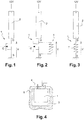
- the figure 1 illustrates a normal operating mode of a power transistor 1 such as a metal-oxide gate field effect transistor, also called a MOSFET, mounted on a printed circuit board.
- a power transistor 1 such as a metal-oxide gate field effect transistor, also called a MOSFET, mounted on a printed circuit board.
- a transistor 1 conventionally comprises a first terminal D called drain, a second terminal S called source and a third terminal G called gate and making it possible to control the opening and closing of the MOSFET.
- Drain D is for example electrically connected to the negative terminal of a heating module 2, in particular via a first electrically conductive track 3 ( figure 4 ), the positive terminal of the heating module 2 being connected to a potential formed for example by the positive terminal of a battery.
- the source S is for example connected to the negative or ground terminal of the battery, in particular by means of a second electrically conductive track 4.
- MOSFET 1 When MOSFET 1 is closed, that is to say when it is in the on state, it has a resistance Rdson whose value is for example of the order of 4 m ⁇ .
- the current flowing through the MOSFET 1 being relatively high, a quantity of heat of for example between 2 W and 3 W is dissipated by the MOSFET 1, in normal operation.
- MOSFET 1 There is also a very low risk that MOSFET 1 will be damaged in operation. In most cases, this damage results in an impedant short-circuit state between the drain D and the source S. Such a degraded state is illustrated on figure 2 .
- the MOSFET 1 behaves as if an impedance 5 (internal to the MOSFET 1) was connected in parallel between the drain D and the source S.
- This impedance 5 has for example a value of the order of 40 m ⁇ .
- the heat then dissipated by the MOSFET 1 is for example of the order of 30 W.
- the degraded material 6 of the printed circuit board acts as a resistance ( figure 3 ).
- the MOSFET 1 ends up opening completely so that the negative terminal of the heating element 2 is connected to the negative or ground terminal of the battery via the resistor 7 formed by the degraded material 6 of the battery. printed circuit board.
- this resistance 7 is for example of the order of 10 ⁇ .
- the heat dissipated by this resistor 7 is then of the order of 10 to 15 W.
- the figure 5 shows an additional electric heating device 10 according to the invention, intended to equip a motor vehicle.
- a heating device 10 is used in particular in the first minutes of use of the motor vehicle, when the engine is not hot enough to ensure the supply of hot air into the passenger compartment of the vehicle.
- This device 10 comprises a support frame 11 of parallelepiped shape on which are mounted parallel heating modules 12 and arranged so as to be traversed by a flow of air to be heated.
- the heating modules 12 are controlled using a control module 13 ( figures 6 ) or driver mounted in a box 14 fixed to the support frame 11.
- Each heating module 12 has two electrodes or terminals referenced + and - at the figure 9 , between which are placed resistive elements 15 ( figure 9 ) Positive temperature coefficient (PTC) type.
- resistive elements 15 figure 9
- PTC Positive temperature coefficient
- Two opposed heat sinks 16 are fixed on the electrodes, so as to increase the exchange surface with the air flow to be heated.
- the heat sinks 16 are for example formed of pleated or corrugated metal ribbons.
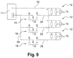
- Each heating module 12 thus comprises a positive terminal electrically connected to the positive terminal of a battery 17, and a negative terminal electrically connected to the negative terminal of the battery 17 via a power transistor 18, such as 'a metal-oxide gate field effect transistor (MOSFET).
- MOSFET metal-oxide gate field effect transistor
- the control module 13 comprises a printed circuit board 19 comprising first zones 20 on which the MOSFETs 18 are mounted and a second zone 21 on which are notably welded or mounted various electrical and electronic components ( figures 7 and 8 ).
- Each first zone 20 has a generally rectangular shape and comprises, on its upper face, a first track 22 ( figure 8 ) extending over the major part of the first zone 20 and connected to the drain D of the corresponding MOSFET 18. More particularly, each MOSFET 18 comprises a sole forming the drain D, in electrical contact with the first track 22 and welded to the latter.
- the second zone 21 of the electronic card 19 comprises an upper face on which are formed respectively three second electrically conductive tracks 23 and three third electrically conductive tracks 24, located generally opposite the corresponding first tracks 22, and a fourth electrically conductive track 25 connected to the negative or ground terminal of the battery 17.
- the fourth track 25 extends over the major part of the second zone and forms a ground plane, as is better described below.
- Each second track 23 is connected to the ground plane 25 by means of a resistor or "shunt” 26 ( figure 6 ) for performing an electric current measurement.
- the value of this “shunt” 26 is very low, of the order of a few milliohms.
- the printed circuit board 19 has three slots 27 located respectively between each first area 20 and the second area 21 of the printed circuit board 19, each slot 27 forming a material discontinuity, at least partial, between the first and second areas 20 , 21 of the printed circuit board 19, said slot 27 being located or interposed in particular between the first and second conductive tracks 22, 23.
- This slot 27 has the general shape of a U (or of an L depending on the applications and the position of the slot) and comprises a base from which two branches extend.
- each MOSFET 18 is connected to the negative terminal of the corresponding heating module 12, via the first corresponding track 22 and a first conductive bar 28 comprising terminations soldered to the first track 22.
- the source S is formed by a first leg 29 of the MOSFET 18 and is connected to the negative terminal or ground of the battery 17, by the intermediary of the second and fourth tracks 23, 25 of the printed circuit board 19, by the intermediary of the corresponding “shunt” 26 and by means of a second conductive bar 30 comprising terminations welded onto the fourth track 25.
- the presence of the “shunt” 26 will be neglected, for reasons of simplification of the presentation.
- the gate G of the MOSFET 18 is formed by a tab 31 serving for the input of a control signal making it possible to control the opening and closing of the MOSFET 18, said tab 31 being welded to the corresponding third track 24 of the printed circuit board 19.
- the electrical connection between the positive terminals of the battery 17 and the heating modules 12 is provided by a third conductive bar 32.
- the various conducting bars 28, 30, 32 are mechanically connected to each other and electrically insulated from each other by a lining 33 overmolded in synthetic material and playing the role of support so that said conducting bars 28, 30, 32 and the lining 33 form a unitary assembly.
- the trim 33 is fixed to the printed circuit board 19.
- Each MOSFET 18 can be opened and closed cyclically, the temperature reached by each heating module 12 then being a function of the opening and closing times of the MOSFET 18.
- the present slots 27 make it possible to avoid the case shown in figure 3 , in which degradation of the material 6 of the printed circuit board 19 can cause a sharp rise in temperature.
- This slot 27 prevents the degraded material 6 from acting in the manner of a resistor 7 placed between the potential of the drain D (first track 22) and that of the source S (second track 23 or fourth track 25). It will be recalled that, taking into account the negligible influence of the “shunt” 26, the potential of the second and fourth tracks 23, 25 is substantially identical.
Landscapes
- Engineering & Computer Science (AREA)
- Physics & Mathematics (AREA)
- Thermal Sciences (AREA)
- Mechanical Engineering (AREA)
- Chemical & Material Sciences (AREA)
- Combustion & Propulsion (AREA)
- General Engineering & Computer Science (AREA)
- Microelectronics & Electronic Packaging (AREA)
- Air-Conditioning For Vehicles (AREA)
- Structure Of Printed Boards (AREA)
- Charge And Discharge Circuits For Batteries Or The Like (AREA)
Claims (6)
- Steuermodul (13) einer elektrischen Vorrichtung (10) aufweisend eine Leiterplatte (19), auf der elektrische und elektronische Bauelemente (26) angebracht sind, und mindestens einen Leistungstransistor (18), der auf einem ersten Bereich (20) der Leiterplatte (19) befestigt ist und einen ersten Anschluss (D), Drain genannt, der mit einer ersten elektrisch leitenden Bahn (22) des ersten Bereichs (20) verbunden ist, einen zweiten Anschluss (S), der Source genannt wird und mit einer zweiten elektrisch leitenden Bahn (23) eines zweiten Bereichs (21) der Leiterplatte (19) verbunden ist, und einen dritten Anschluss (G), Gate genannt, aufweist, dadurch gekennzeichnet, dass die Leiterplatte (19) mindestens eine Öffnung (27) aufweist, die eine wenigstens teilweise Materialdiskontinuität zwischen dem ersten und zweiten Bereich (20, 21) der Leiterplatte (19) bildet, wobei sich die Öffnung (27) zwischen der ersten und zweiten Leiterbahn (22, 23) befindet.
- Steuermodul (13) nach Anspruch 1, dadurch gekennzeichnet, dass der Leistungstransistor (18) einen Boden, der den Drain (D) bildet, der mit der ersten Bahn (22) in elektrischem Kontakt steht, und ein Bein (29), das die Source (S) bildet, das mit der zweiten Bahn (23) elektrisch verbunden ist, aufweist.
- Steuermodul (13) nach Anspruch 1 oder 2, dadurch gekennzeichnet, dass die Öffnung ein Spalt (27) ist, der den ersten Bereich (20) der Leiterplatte (19) wenigstens teilweise umgibt.
- Steuermodul (13) nach Anspruch 3, dadurch gekennzeichnet, dass der Spalt (27) eine allgemeine Form eines U oder L aufweist und eine Basis aufweist, von welcher sich wenigstens ein Schenkel erstreckt.
- Heizvorrichtung (10), insbesondere für ein Kraftfahrzeug, aufweisend ein Steuermodul (13) nach einem der Ansprüche 1 bis 4.
- Heizvorrichtung nach Anspruch 5, dadurch gekennzeichnet, dass sie mindestens ein Heizmodul (12) umfasst, das einen ersten Anschluss, der mit einem ersten Anschluss einer Batterie (17) elektrisch verbunden ist, einen zweiten Anschluss, der mittels eines ersten elektrischen Verbindungselements (28) mit dem Drain (D) des Leistungstransistors (18) elektrisch verbunden ist, umfasst, wobei ein zweiter Anschluss der Batterie (17) mittels eines zweiten elektrischen Verbindungselements (30) mit der Source (S) des Leistungstransistors (18) elektrisch verbunden ist, wobei der erste Anschluss des Moduls (12) mittels eines dritten elektrischen Verbindungselements (32) mit dem ersten Anschluss der Batterie (17) elektrisch verbunden ist, wobei die drei Verbindungselemente (28, 30, 32) mittels einer elektrisch isolierenden Einfassung (33) mechanisch miteinander verbunden sind.
Applications Claiming Priority (2)
| Application Number | Priority Date | Filing Date | Title |
|---|---|---|---|
| FR1352738A FR3004057B1 (fr) | 2013-03-26 | 2013-03-26 | Module de commande d'un appareil electrique |
| PCT/EP2014/055700 WO2014154581A1 (fr) | 2013-03-26 | 2014-03-21 | Module de commande d'un appareil électrique |
Publications (2)
| Publication Number | Publication Date |
|---|---|
| EP2979523A1 EP2979523A1 (de) | 2016-02-03 |
| EP2979523B1 true EP2979523B1 (de) | 2021-07-14 |
Family
ID=48407739
Family Applications (1)
| Application Number | Title | Priority Date | Filing Date |
|---|---|---|---|
| EP14714204.6A Active EP2979523B1 (de) | 2013-03-26 | 2014-03-21 | Steuermodul für eine elektrische anwendung |
Country Status (7)
| Country | Link |
|---|---|
| US (1) | US10322619B2 (de) |
| EP (1) | EP2979523B1 (de) |
| JP (1) | JP6133488B2 (de) |
| KR (1) | KR101799171B1 (de) |
| CN (1) | CN105052247B (de) |
| FR (1) | FR3004057B1 (de) |
| WO (1) | WO2014154581A1 (de) |
Families Citing this family (5)
| Publication number | Priority date | Publication date | Assignee | Title |
|---|---|---|---|---|
| US10693344B2 (en) * | 2014-12-18 | 2020-06-23 | Black & Decker Inc. | Packaging of a control module for a brushless motor |
| FR3031802B1 (fr) * | 2015-01-21 | 2019-09-27 | Valeo Systemes Thermiques | Radiateur electrique additionnel pour vehicule automobile |
| DE102016203906A1 (de) * | 2016-03-10 | 2017-09-28 | Robert Bosch Gmbh | Halbleiterbauelement, insbesondere Leistungstransistor |
| FR3104240A1 (fr) * | 2019-12-05 | 2021-06-11 | Valeo Systemes Thermiques | Dispositif de chauffage de fluide, notamment destiné à un véhicule |
| CN212046774U (zh) * | 2019-12-30 | 2020-12-01 | 法雷奥汽车空调湖北有限公司 | 电加热装置、供暖、通风和/或空调装置和机动车辆 |
Citations (1)
| Publication number | Priority date | Publication date | Assignee | Title |
|---|---|---|---|---|
| JPS5927556A (ja) * | 1982-08-04 | 1984-02-14 | Hanshin Electric Co Ltd | 要放熱電気部品の取付方法 |
Family Cites Families (14)
| Publication number | Priority date | Publication date | Assignee | Title |
|---|---|---|---|---|
| JP2586817B2 (ja) * | 1993-12-15 | 1997-03-05 | 日本電気株式会社 | 混成集積回路装置 |
| ES2092413T3 (es) * | 1995-02-18 | 1996-11-16 | Hewlett Packard Gmbh | Conjunto electronico con caracteristicas termicas mejoradas. |
| JP3068488B2 (ja) * | 1997-03-13 | 2000-07-24 | 米沢日本電気株式会社 | プリント基板 |
| JP3876563B2 (ja) * | 1999-03-19 | 2007-01-31 | 住友電装株式会社 | 電気接続箱 |
| US6320748B1 (en) * | 2000-03-17 | 2001-11-20 | Celestica International Inc. | Power heatsink for a circuit board |
| DE102004006533A1 (de) * | 2004-02-11 | 2005-09-01 | Conti Temic Microelectronic Gmbh | Elektrisch leitfähiger Kontaktstift zum Einpressen in eine Öffnung einer Leiterplatte sowie elektrische Baugruppe mit einem solchen Kontaktstift |
| US7479835B2 (en) * | 2005-09-15 | 2009-01-20 | Nihon Dempa Kogyo Co., Ltd. | Constant temperature type crystal oscillator for high stability |
| DE102006009812B4 (de) * | 2006-03-01 | 2008-09-04 | Beru Ag | Montageanordnung für mehrere Leistungshalbleiter und Schaltung mit einer solchen Montageanordnung |
| DE502007005351D1 (de) * | 2007-07-20 | 2010-11-25 | Eberspaecher Catem Gmbh & Co K | Elektrische Heizvorrichtung insbesondere für Kraftfahrzeuge |
| WO2009096966A1 (en) * | 2008-01-31 | 2009-08-06 | Hewlett-Packard Development Company, L.P. | Insulating aperture in printed circuit boards |
| US8242418B2 (en) * | 2008-06-27 | 2012-08-14 | Kuo Kuanghung | Golf ball bag with temperature controlling device |
| JP5422271B2 (ja) * | 2009-06-25 | 2014-02-19 | 株式会社東芝 | 電子レンジのトランス搭載基板装置 |
| EP2330865B1 (de) * | 2009-12-03 | 2015-10-21 | Eberspächer catem GmbH & Co. KG | Elektrische Heizvorrichtung |
| FR2954606B1 (fr) * | 2009-12-23 | 2019-05-10 | Valeo Systemes Thermiques | Connecteur pour carte a circuit electrique, carte a circuit electrique et dispositif de chauffage electrique correspondants |
-
2013
- 2013-03-26 FR FR1352738A patent/FR3004057B1/fr not_active Expired - Fee Related
-
2014
- 2014-03-21 KR KR1020157026494A patent/KR101799171B1/ko active IP Right Grant
- 2014-03-21 EP EP14714204.6A patent/EP2979523B1/de active Active
- 2014-03-21 JP JP2016504593A patent/JP6133488B2/ja active Active
- 2014-03-21 CN CN201480018060.4A patent/CN105052247B/zh active Active
- 2014-03-21 WO PCT/EP2014/055700 patent/WO2014154581A1/fr active Application Filing
- 2014-03-21 US US14/778,642 patent/US10322619B2/en active Active
Patent Citations (1)
| Publication number | Priority date | Publication date | Assignee | Title |
|---|---|---|---|---|
| JPS5927556A (ja) * | 1982-08-04 | 1984-02-14 | Hanshin Electric Co Ltd | 要放熱電気部品の取付方法 |
Also Published As
| Publication number | Publication date |
|---|---|
| JP2016515761A (ja) | 2016-05-30 |
| FR3004057B1 (fr) | 2017-02-17 |
| WO2014154581A1 (fr) | 2014-10-02 |
| US10322619B2 (en) | 2019-06-18 |
| CN105052247B (zh) | 2017-12-22 |
| CN105052247A (zh) | 2015-11-11 |
| EP2979523A1 (de) | 2016-02-03 |
| KR20150123290A (ko) | 2015-11-03 |
| KR101799171B1 (ko) | 2017-11-17 |
| US20160039267A1 (en) | 2016-02-11 |
| JP6133488B2 (ja) | 2017-05-24 |
| FR3004057A1 (fr) | 2014-10-03 |
Similar Documents
| Publication | Publication Date | Title |
|---|---|---|
| EP2979523B1 (de) | Steuermodul für eine elektrische anwendung | |
| EP2517307B1 (de) | Stecker für eine elektrische leiterplatte, zugehörige elektrische leiterplatte und elektrische heizvorrichtung | |
| FR2808131A1 (fr) | Connecteur electrique | |
| EP1998406B1 (de) | Elektrische Anschlussvorrichtung zwischen einer Stromversorgungsquelle und einem elektrischen Heizkörper und Anwendungsverfahren einer solchen Anschlussvorrichtung | |
| EP2979521A1 (de) | Steuermodul für eine elektrische anwendung | |
| FR3075552A1 (fr) | Dispositif de chauffage electrique avec moyens de mise a la masse | |
| LU83203A1 (fr) | Dispositif de chauffage applicable a un filtre a carburant | |
| EP2979328A1 (de) | Steuermodul für eine elektrische anwendung | |
| EP3727911B1 (de) | Elektrische heizeinheit mit erdung | |
| FR3004056A1 (fr) | Module de commande d'un appareil electrique | |
| FR2994892A1 (fr) | Dispositif de chauffage electrique de fluide pour vehicule automobile, circuit de chauffage et appareil de chauffage et/ou de climatisation associes | |
| FR2477314A1 (fr) | Element de commutation electrique de preference contacteur electromagnetique | |
| EP1862782A1 (de) | Resistive Sonde eines Sensors für die Erkennung eines Flüssigkeitspegels | |
| EP1810041A1 (de) | Batteriesensorenvorrichtung | |
| EP1562208A1 (de) | Thermischer Schalter für ein elektronisches Bauelement | |
| FR3120332A1 (fr) | Module de commande, dispositif électrique et procédé de détection d’enlèvement d’un capot d’un module de commande correspondants | |
| EP1411577B1 (de) | Vorrichtung zur Feststellung des Korrosionszustandes einer Batterie, insbesondere einer Kraftfahrzeugbatterie | |
| FR3069404A1 (fr) | Dispositif de chauffage, notamment pour boitier de climatisation d'un vehicule automobile | |
| FR3086736A1 (fr) | Boitier d'interface electronique de commande d'un dispositif de chauffage electrique | |
| FR3095569A1 (fr) | Dispositif de chauffage électrique et installation de chauffage et/ou ventilation et/ou climatisation associée | |
| FR3112666A1 (fr) | Batterie de secours pourvue d’un connecteur électrique | |
| FR3072614A1 (fr) | Dispositif de chauffage, et boitier de climatisation d'un vehicule automobile equipe d'un tel dispositif | |
| WO2014183864A1 (fr) | Procede et dispositif de lecture de l'etat de variables de contact d'un vehicule automobile |
Legal Events
| Date | Code | Title | Description |
|---|---|---|---|
| PUAI | Public reference made under article 153(3) epc to a published international application that has entered the european phase |
Free format text: ORIGINAL CODE: 0009012 |
|
| 17P | Request for examination filed |
Effective date: 20150925 |
|
| AK | Designated contracting states |
Kind code of ref document: A1 Designated state(s): AL AT BE BG CH CY CZ DE DK EE ES FI FR GB GR HR HU IE IS IT LI LT LU LV MC MK MT NL NO PL PT RO RS SE SI SK SM TR |
|
| AX | Request for extension of the european patent |
Extension state: BA ME |
|
| DAX | Request for extension of the european patent (deleted) | ||
| STAA | Information on the status of an ep patent application or granted ep patent |
Free format text: STATUS: EXAMINATION IS IN PROGRESS |
|
| 17Q | First examination report despatched |
Effective date: 20190118 |
|
| STAA | Information on the status of an ep patent application or granted ep patent |
Free format text: STATUS: EXAMINATION IS IN PROGRESS |
|
| GRAP | Despatch of communication of intention to grant a patent |
Free format text: ORIGINAL CODE: EPIDOSNIGR1 |
|
| STAA | Information on the status of an ep patent application or granted ep patent |
Free format text: STATUS: GRANT OF PATENT IS INTENDED |
|
| RIC1 | Information provided on ipc code assigned before grant |
Ipc: H05K 1/02 20060101AFI20210409BHEP Ipc: F24H 3/04 20060101ALI20210409BHEP Ipc: F24H 9/20 20060101ALI20210409BHEP |
|
| INTG | Intention to grant announced |
Effective date: 20210426 |
|
| RAP3 | Party data changed (applicant data changed or rights of an application transferred) |
Owner name: VALEO SYSTEMES THERMIQUES |
|
| GRAS | Grant fee paid |
Free format text: ORIGINAL CODE: EPIDOSNIGR3 |
|
| GRAA | (expected) grant |
Free format text: ORIGINAL CODE: 0009210 |
|
| STAA | Information on the status of an ep patent application or granted ep patent |
Free format text: STATUS: THE PATENT HAS BEEN GRANTED |
|
| AK | Designated contracting states |
Kind code of ref document: B1 Designated state(s): AL AT BE BG CH CY CZ DE DK EE ES FI FR GB GR HR HU IE IS IT LI LT LU LV MC MK MT NL NO PL PT RO RS SE SI SK SM TR |
|
| REG | Reference to a national code |
Ref country code: GB Ref legal event code: FG4D Free format text: NOT ENGLISH |
|
| REG | Reference to a national code |
Ref country code: IE Ref legal event code: FG4D Free format text: LANGUAGE OF EP DOCUMENT: FRENCH |
|
| REG | Reference to a national code |
Ref country code: DE Ref legal event code: R096 Ref document number: 602014078736 Country of ref document: DE |
|
| REG | Reference to a national code |
Ref country code: AT Ref legal event code: REF Ref document number: 1411694 Country of ref document: AT Kind code of ref document: T Effective date: 20210815 |
|
| REG | Reference to a national code |
Ref country code: LT Ref legal event code: MG9D |
|
| REG | Reference to a national code |
Ref country code: NL Ref legal event code: MP Effective date: 20210714 |
|
| REG | Reference to a national code |
Ref country code: AT Ref legal event code: MK05 Ref document number: 1411694 Country of ref document: AT Kind code of ref document: T Effective date: 20210714 |
|
| PG25 | Lapsed in a contracting state [announced via postgrant information from national office to epo] |
Ref country code: LT Free format text: LAPSE BECAUSE OF FAILURE TO SUBMIT A TRANSLATION OF THE DESCRIPTION OR TO PAY THE FEE WITHIN THE PRESCRIBED TIME-LIMIT Effective date: 20210714 Ref country code: BG Free format text: LAPSE BECAUSE OF FAILURE TO SUBMIT A TRANSLATION OF THE DESCRIPTION OR TO PAY THE FEE WITHIN THE PRESCRIBED TIME-LIMIT Effective date: 20211014 Ref country code: AT Free format text: LAPSE BECAUSE OF FAILURE TO SUBMIT A TRANSLATION OF THE DESCRIPTION OR TO PAY THE FEE WITHIN THE PRESCRIBED TIME-LIMIT Effective date: 20210714 Ref country code: FI Free format text: LAPSE BECAUSE OF FAILURE TO SUBMIT A TRANSLATION OF THE DESCRIPTION OR TO PAY THE FEE WITHIN THE PRESCRIBED TIME-LIMIT Effective date: 20210714 Ref country code: ES Free format text: LAPSE BECAUSE OF FAILURE TO SUBMIT A TRANSLATION OF THE DESCRIPTION OR TO PAY THE FEE WITHIN THE PRESCRIBED TIME-LIMIT Effective date: 20210714 Ref country code: NL Free format text: LAPSE BECAUSE OF FAILURE TO SUBMIT A TRANSLATION OF THE DESCRIPTION OR TO PAY THE FEE WITHIN THE PRESCRIBED TIME-LIMIT Effective date: 20210714 Ref country code: PT Free format text: LAPSE BECAUSE OF FAILURE TO SUBMIT A TRANSLATION OF THE DESCRIPTION OR TO PAY THE FEE WITHIN THE PRESCRIBED TIME-LIMIT Effective date: 20211115 Ref country code: NO Free format text: LAPSE BECAUSE OF FAILURE TO SUBMIT A TRANSLATION OF THE DESCRIPTION OR TO PAY THE FEE WITHIN THE PRESCRIBED TIME-LIMIT Effective date: 20211014 Ref country code: HR Free format text: LAPSE BECAUSE OF FAILURE TO SUBMIT A TRANSLATION OF THE DESCRIPTION OR TO PAY THE FEE WITHIN THE PRESCRIBED TIME-LIMIT Effective date: 20210714 Ref country code: SE Free format text: LAPSE BECAUSE OF FAILURE TO SUBMIT A TRANSLATION OF THE DESCRIPTION OR TO PAY THE FEE WITHIN THE PRESCRIBED TIME-LIMIT Effective date: 20210714 Ref country code: RS Free format text: LAPSE BECAUSE OF FAILURE TO SUBMIT A TRANSLATION OF THE DESCRIPTION OR TO PAY THE FEE WITHIN THE PRESCRIBED TIME-LIMIT Effective date: 20210714 |
|
| PG25 | Lapsed in a contracting state [announced via postgrant information from national office to epo] |
Ref country code: PL Free format text: LAPSE BECAUSE OF FAILURE TO SUBMIT A TRANSLATION OF THE DESCRIPTION OR TO PAY THE FEE WITHIN THE PRESCRIBED TIME-LIMIT Effective date: 20210714 Ref country code: LV Free format text: LAPSE BECAUSE OF FAILURE TO SUBMIT A TRANSLATION OF THE DESCRIPTION OR TO PAY THE FEE WITHIN THE PRESCRIBED TIME-LIMIT Effective date: 20210714 Ref country code: GR Free format text: LAPSE BECAUSE OF FAILURE TO SUBMIT A TRANSLATION OF THE DESCRIPTION OR TO PAY THE FEE WITHIN THE PRESCRIBED TIME-LIMIT Effective date: 20211015 |
|
| REG | Reference to a national code |
Ref country code: DE Ref legal event code: R097 Ref document number: 602014078736 Country of ref document: DE |
|
| PG25 | Lapsed in a contracting state [announced via postgrant information from national office to epo] |
Ref country code: DK Free format text: LAPSE BECAUSE OF FAILURE TO SUBMIT A TRANSLATION OF THE DESCRIPTION OR TO PAY THE FEE WITHIN THE PRESCRIBED TIME-LIMIT Effective date: 20210714 |
|
| PLBE | No opposition filed within time limit |
Free format text: ORIGINAL CODE: 0009261 |
|
| STAA | Information on the status of an ep patent application or granted ep patent |
Free format text: STATUS: NO OPPOSITION FILED WITHIN TIME LIMIT |
|
| PG25 | Lapsed in a contracting state [announced via postgrant information from national office to epo] |
Ref country code: SM Free format text: LAPSE BECAUSE OF FAILURE TO SUBMIT A TRANSLATION OF THE DESCRIPTION OR TO PAY THE FEE WITHIN THE PRESCRIBED TIME-LIMIT Effective date: 20210714 Ref country code: SK Free format text: LAPSE BECAUSE OF FAILURE TO SUBMIT A TRANSLATION OF THE DESCRIPTION OR TO PAY THE FEE WITHIN THE PRESCRIBED TIME-LIMIT Effective date: 20210714 Ref country code: RO Free format text: LAPSE BECAUSE OF FAILURE TO SUBMIT A TRANSLATION OF THE DESCRIPTION OR TO PAY THE FEE WITHIN THE PRESCRIBED TIME-LIMIT Effective date: 20210714 Ref country code: EE Free format text: LAPSE BECAUSE OF FAILURE TO SUBMIT A TRANSLATION OF THE DESCRIPTION OR TO PAY THE FEE WITHIN THE PRESCRIBED TIME-LIMIT Effective date: 20210714 Ref country code: CZ Free format text: LAPSE BECAUSE OF FAILURE TO SUBMIT A TRANSLATION OF THE DESCRIPTION OR TO PAY THE FEE WITHIN THE PRESCRIBED TIME-LIMIT Effective date: 20210714 Ref country code: AL Free format text: LAPSE BECAUSE OF FAILURE TO SUBMIT A TRANSLATION OF THE DESCRIPTION OR TO PAY THE FEE WITHIN THE PRESCRIBED TIME-LIMIT Effective date: 20210714 |
|
| 26N | No opposition filed |
Effective date: 20220419 |
|
| PG25 | Lapsed in a contracting state [announced via postgrant information from national office to epo] |
Ref country code: IT Free format text: LAPSE BECAUSE OF FAILURE TO SUBMIT A TRANSLATION OF THE DESCRIPTION OR TO PAY THE FEE WITHIN THE PRESCRIBED TIME-LIMIT Effective date: 20210714 |
|
| PG25 | Lapsed in a contracting state [announced via postgrant information from national office to epo] |
Ref country code: MC Free format text: LAPSE BECAUSE OF FAILURE TO SUBMIT A TRANSLATION OF THE DESCRIPTION OR TO PAY THE FEE WITHIN THE PRESCRIBED TIME-LIMIT Effective date: 20210714 |
|
| REG | Reference to a national code |
Ref country code: CH Ref legal event code: PL |
|
| GBPC | Gb: european patent ceased through non-payment of renewal fee |
Effective date: 20220321 |
|
| REG | Reference to a national code |
Ref country code: BE Ref legal event code: MM Effective date: 20220331 |
|
| PG25 | Lapsed in a contracting state [announced via postgrant information from national office to epo] |
Ref country code: LU Free format text: LAPSE BECAUSE OF NON-PAYMENT OF DUE FEES Effective date: 20220321 Ref country code: LI Free format text: LAPSE BECAUSE OF NON-PAYMENT OF DUE FEES Effective date: 20220331 Ref country code: IE Free format text: LAPSE BECAUSE OF NON-PAYMENT OF DUE FEES Effective date: 20220321 Ref country code: GB Free format text: LAPSE BECAUSE OF NON-PAYMENT OF DUE FEES Effective date: 20220321 Ref country code: CH Free format text: LAPSE BECAUSE OF NON-PAYMENT OF DUE FEES Effective date: 20220331 |
|
| PG25 | Lapsed in a contracting state [announced via postgrant information from national office to epo] |
Ref country code: BE Free format text: LAPSE BECAUSE OF NON-PAYMENT OF DUE FEES Effective date: 20220331 |
|
| P01 | Opt-out of the competence of the unified patent court (upc) registered |
Effective date: 20230528 |
|
| PG25 | Lapsed in a contracting state [announced via postgrant information from national office to epo] |
Ref country code: HU Free format text: LAPSE BECAUSE OF FAILURE TO SUBMIT A TRANSLATION OF THE DESCRIPTION OR TO PAY THE FEE WITHIN THE PRESCRIBED TIME-LIMIT; INVALID AB INITIO Effective date: 20140321 |
|
| PG25 | Lapsed in a contracting state [announced via postgrant information from national office to epo] |
Ref country code: MK Free format text: LAPSE BECAUSE OF FAILURE TO SUBMIT A TRANSLATION OF THE DESCRIPTION OR TO PAY THE FEE WITHIN THE PRESCRIBED TIME-LIMIT Effective date: 20210714 Ref country code: CY Free format text: LAPSE BECAUSE OF FAILURE TO SUBMIT A TRANSLATION OF THE DESCRIPTION OR TO PAY THE FEE WITHIN THE PRESCRIBED TIME-LIMIT Effective date: 20210714 |
|
| PGFP | Annual fee paid to national office [announced via postgrant information from national office to epo] |
Ref country code: DE Payment date: 20240307 Year of fee payment: 11 |
|
| PGFP | Annual fee paid to national office [announced via postgrant information from national office to epo] |
Ref country code: FR Payment date: 20240325 Year of fee payment: 11 |
|
| PG25 | Lapsed in a contracting state [announced via postgrant information from national office to epo] |
Ref country code: MT Free format text: LAPSE BECAUSE OF FAILURE TO SUBMIT A TRANSLATION OF THE DESCRIPTION OR TO PAY THE FEE WITHIN THE PRESCRIBED TIME-LIMIT Effective date: 20210714 |