EP2979073B1 - Lagersystem mit sensoreinheit. - Google Patents
Lagersystem mit sensoreinheit. Download PDFInfo
- Publication number
- EP2979073B1 EP2979073B1 EP13712773.4A EP13712773A EP2979073B1 EP 2979073 B1 EP2979073 B1 EP 2979073B1 EP 13712773 A EP13712773 A EP 13712773A EP 2979073 B1 EP2979073 B1 EP 2979073B1
- Authority
- EP
- European Patent Office
- Prior art keywords
- sensor unit
- recess
- sensor
- bearing
- housing
- Prior art date
- Legal status (The legal status is an assumption and is not a legal conclusion. Google has not performed a legal analysis and makes no representation as to the accuracy of the status listed.)
- Active
Links
Images

Classifications
-
- G—PHYSICS
- G01—MEASURING; TESTING
- G01M—TESTING STATIC OR DYNAMIC BALANCE OF MACHINES OR STRUCTURES; TESTING OF STRUCTURES OR APPARATUS, NOT OTHERWISE PROVIDED FOR
- G01M13/00—Testing of machine parts
- G01M13/04—Bearings
- G01M13/045—Acoustic or vibration analysis
Definitions
- the invention relates to a sensor unit for use with bearings, a bearing including such a sensor unit and a control unit for controlling or monitoring an apparatus including such a bearing.
- sensor units which may be mounted in a housing or on the outer or inner ring of the bearing.
- Sensors which may be used are e.g. temperature sensors and rotation sensors.
- sensor units are mounted on a surface of a bearing, e.g. on an axial side face of a bearing outer ring, wherein the sensors are arranged in a housing which is fixed to the surface of the bearing by adhesion or with screws.
- This way of mounting the sensors has drawbacks, in particular in terms of robustness and precision of measurement.
- the position of the sensor housing on the surface is susceptible for damages due to unintended collisions with other parts or tools used during the assembly of the device provided with the bearing and the sensor may be fairly remote from the rolling elements such as rollers or balls the properties of which are measured.
- US 2006/0070460 discloses multiple strain gauge sensors being located in a groove on an outer diameter of an outer ring.
- the invention tries to overcome the above drawbacks of the prior art by providing a sensor unit, a bearing and a pertinent control unit as described in the claims.
- the invention starts from a sensor unit for a bearing including at least one inner ring and at least one outer ring, wherein the sensor unit in configured to detect at least one state variable of the bearing.
- the state variables may include amplitudes of vibrations, acoustic emissions, temperature or strain values.
- the sensor unit is configured to be embedded in a recess of the inner ring or of the outer ring of the bearing.
- the sensors can be brought closer to the rolling elements such as rollers, tapered rollers, needles or balls of the bearing while at the same time protecting the sensor from collisions with tools or other parts of the device in which the bearing with the sensor unit is mounted.
- the invention is mainly applicable to large-size bearings with diameters of several tenths of centimeters such as bearings for wind turbines, generators, ship propellers or the like.
- bearings for wind turbines, generators, ship propellers or the like are especially applicable to large-size bearings with diameters of several tenths of centimeters.
- Special advantages of the invention may be achieved in the context of devices requiring a detailed remote monitoring, in particular wind turbines.
- the sensor unit includes multiple sensors in one single sensor housing. This may help to reduce costs of multiple housings and multiple recesses to be provided in the rings of the bearing and facilitates the assembly.
- the sensor unit is provided with a wireless transmitter for transmitting signals obtained by the sensor unit.
- machining of a suitable recess mating with the sensor unit is particularly simple and cost-saving when the sensor unit has a housing with a circular cross-section axially fitted into the recess.
- the housing of the sensor unit comprises at least one deeper portion and one shallower portion, wherein bolts for fixing the sensor unit or larger circuit boards or circuit elements may be provided in the shallower portion in a well-protected way and only the parts of the sensor which need to be as close as possible to the rolling elements of the bearing may be provided in the bottom portion of the deeper portion.
- the machining of a recess mating with a housing of this shape is particularly simple and cost-saving if the deeper portion and the shallower portion are formed in essentially cylindrical shapes of different diameters.
- a bottom face of the sensor unit including at least one contact plate is configured to abut with a bottom surface of the deeper portion of the recess. This helps to bring the contact plate as close as possible to the rolling elements of the bearing.
- the sensor unit includes at least one strain sensor. It is in particular the strain measurement which is greatly improved in precision by bringing the sensor close to the rolling elements.
- the sensor unit may include at least one acoustic emission and/or vibration sensor.
- the sensor unit includes a circlip to hold the sensor in the recess.
- the use of a circlip may help to avoid the use of screws and bolts, which affect the strain measurement in a detrimental way.
- the circlip may in particular engage with a circumferential notch provided in the inner surface of the recess.
- Screws for closing the housing may be avoided by using a housing which is sealed with an adhesive bond, in particular with ultra-sonic welding.
- the invention proposes a bearing including an inner ring, an outer ring and a sensor unit as described above.
- a recess is provided in the outer ring or in the inner ring and the sensor unit is embedded in the recess.
- the recess may in particular comprise a deeper portion and a shallower portion mating with the deeper portion and the shallower portion of the sensor unit.
- the recess may be provided with a circumferential notch for receiving the circlip for retaining the sensor unit in the recess.
- the circlip could be replaced with other elastical elements engaging with notches or holes in the side walls of the recess.
- a further aspect of the invention relates to a control apparatus configured to receive data from the sensor unit and to generate status information or warning signals based on the received data.
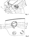
- Fig. 1 shows a cross-sectional view of a sensor unit 14 embedded in an inner ring 10 of a taper roller bearing including an inner ring and an outer ring 12.
- the sensor unit 14 is embedded in a recess 16 machined in the axially outer surface of the inner ring 10.
- the recess 16 comprises a deeper portion 16a and a shallower portion 16b, each being formed as concentrical bores with different diameters such that the shallower portion 16b forms a step.
- the sensor unit 14 comprises a housing 18 formed with a T-shaped cross-section mating with the shape of the recess 16 and the housing 18 of the sensor element is fitted into the recess 16.
- a top-surface of the sensor unit 14 is flush with the axial side surface of the inner ring 10 and the sensor unit 14 is fixed in the recess 16 by means of screws 28 engaging with threaded bores (not shown) in the shallower portion 16b of the recess 16.
- the sensor unit 14 comprises a circuit board 30 with a diameter larger than the diameter of the deeper portion 16a and is arranged in the transversal bar of the T-shape of the housing 18.
- a wireless transmitter 20 including an antenna is arranged on the top side of the housing 18.
- Fig. 2 illustrates a perspective view of the sensor unit 14 as mounted in the inner ring 10.
- a connector 32 with a wire is guided out of the housing 18 and enables to read out data or update firmware of a processor provided in the sensor unit 14 in a wired manner.
- the wireless transmitter 20 or the connector 32 may be provided alternatively or in combination.
- Fig. 3 is a perspective view of the sensor unit 14 isolated from the recess 16.
- a plastic cover 34 of the housing 18 of the sensor unit 14 is fixed to a bottom part of the housing 18 by means of screws 36.
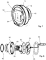
- Fig. 4 shows an exploded view of the sensor unit 14 according to the invention.
- the circuit board 30 is provided with a processor and a wireless transmitter units 20 and connected via flexible elements with a bottom part of the sensor unit 14 including the actual sensors and contact plates 38, 40 fitted into through holes (not shown) in the bottom surface of the lower part of the housing 18.
- An O-ring 42 is provided and engages with a circumferential notch 44 in the circumferential outer wall of the bottom part of the housing 18 and protects the contact plates 38, 40 from being contaminated by penetrating oil or other liquids.
- the contact plates 38, 40 are configured to be directly pressed against a bottom surface of the recess 16 by means of springs 46.
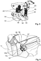
- Fig. 5 shows the bottom part of the sensor unit 14 including the contact plates 38, 40 in more detail.
- the first contact plate 38 is a metallic contact plate equipped with a vibration sensor 48, an acoustic emission sensor 50 and a temperature sensor 52.
- the second contact plate 40 is a contact plate of a strain sensor 54 formed as a friction strain gage.
- the sensors 48-54 are mounted on flexible circuit boards 53 adhered to the actual contact plates 38, 40.
- Figs. 6 to 8 show a second embodiment of the invention.
- the same reference numbers are used for features with similar functions. The description is limited to differences to the embodiment of Figs. 1 to 5 and it is referred to the above description of Figs. 1 to 5 for details of features which are unchanged.
- the sensor unit 14 of the second embodiment is provided with a circlip 56 engaging with a notch 58 in the circumferential side surface of the shallower portion 16b of the recess 16.
- the notch 58 is deep enough to securely fix the sensor unit 14 in combination with the circlip 56 and its depth is chosen such that the outer diameter of the notch 58 is slightly smaller than the outer diameter of the circlip 56 in an unloaded configuration.
- the width of the notch 58 corresponds to the thickness of the circlip 56 such that the circlip 56 may be easily fitted into the notch while axial play of the circlip 56 is avoided. It is to be noted that the pressure of the springs 46 pushes the sensor unit 14 in the direction out of the housing 18 and this force is retained by the circlip 56.
- Fig. 7 shows the sensor unit 14 in a perspective view. It should be noted that no screws are provided for closing the cover plate 34 of the housing 18 because the cover plate 34 is adhered to the housing 18 using ultra-sonic welding.
Landscapes
- Physics & Mathematics (AREA)
- Acoustics & Sound (AREA)
- General Physics & Mathematics (AREA)
Claims (13)
- Sensoreinheit für ein Lager, einschließlich mindestens eines Innenrings (10) und mindestens eines Außenrings (12), wobei die Sensoreinheit (14) dazu ausgelegt ist, mindestens eine Zustandsgröße des Lagers zu erkennen,
wobei die Sensoreinheit (14) dazu ausgelegt ist, in eine Aussparung (16) des Innenrings (10) oder des Außenrings (12) eingebettet zu sein,
dadurch gekennzeichnet, dass
die Sensoreinheit (14) mehrere Sensoren in einem Sensorgehäuse (18) einschließt, wobei das Gehäuse einen kreisförmigen Querschnitt aufweist, der axial in die Aussparung (16) eingepasst ist. - Sensoreinheit nach Anspruch 1,
dadurch gekennzeichnet, dass
die Sensoreinheit (14) mit einem drahtlosen Sender (20) zum Übertragen von Signalen, die durch die Sensoreinheit (14) erhalten werden, versehen ist. - Sensoreinheit nach einem der vorstehenden Ansprüche,
dadurch gekennzeichnet, dass
das Gehäuse (18) der Sensoreinheit (14) mindestens einen tieferen Abschnitt (22) und einen flacheren Abschnitt (24) umfasst. - Sensoreinheit nach Anspruch 3,
dadurch gekennzeichnet, dass
der tiefere Abschnitt (22) und der flachere Abschnitt (24) in im Wesentlichen zylindrischen Formen mit verschiedenen Durchmessern gebildet sind. - Sensoreinheit nach Anspruch 3 oder 4,
dadurch gekennzeichnet, dass
eine Bodenfläche der Sensoreinheit (14), einschließlich mindestens einer Kontaktplatte, dazu ausgelegt ist, an die eine Unterseite eines tieferen Abschnitts (16a) der Aussparung (16) zu stoßen. - Sensoreinheit nach einem der vorstehenden Ansprüche,
dadurch gekennzeichnet, dass
die Sensoreinheit (14) mindestens einen Dehnungssensor (54) einschließt. - Sensoreinheit nach einem der vorstehenden Ansprüche,
dadurch gekennzeichnet, dass
die Sensoreinheit (14) mindestens einen Schallemissions- und/oder Schwingungssensor (48, 50) einschließt. - Sensoreinheit nach einem der vorstehenden Ansprüche,
dadurch gekennzeichnet, dass
die Sensoreinheit (14) einen Sicherungsring (56) einschließt, um die Sensoreinheit (14) in der Aussparung (16) zu halten. - Sensoreinheit nach einem der vorstehenden Ansprüche,
dadurch gekennzeichnet, dass
die Sensoreinheit (14) ein Gehäuse (18) einschließt, das unter Verwendung einer Klebverbindung abgedichtet ist. - Lager, einschließlich eines Außenrings (12) und eines Innenrings (10), einer Sensoreinheit (14) nach einem der vorstehenden Ansprüche und einer Aussparung (16) in dem Außenring (12) oder dem Innenring (14) zum Einbetten der Sensoreinheit (14).
- Lager nach Anspruch 10,
dadurch gekennzeichnet, dass
die Aussparung (16) einen tieferen Abschnitt (16a) und einen flacheren Abschnitt (16b) umfasst, die mit einem tieferen Abschnitt (22) und einem flacheren Abschnitt (24) der Sensoreinheit (14) zusammenpassen. - Lagereinheit nach Anspruch 10 oder 11,
dadurch gekennzeichnet, dass
die Aussparung (16) mit einer umfänglichen Einkerbung (56) zum Aufnehmen eines Sicherungsrings zum Fixieren der Sensoreinheit (14) in der Aussparung (16) versehen ist. - Steuereinheit zum Steuern zum Überwachen einer Einrichtung, einschließlich eines Lagers nach einem der Ansprüche 10 - 12, wobei die Steuereinheit dazu ausgelegt ist, Daten von der Sensoreinheit (14) zu empfangen und Statusinformationen oder Warnsignale basierend auf den empfangenen Daten zu erzeugen.
Applications Claiming Priority (1)
| Application Number | Priority Date | Filing Date | Title |
|---|---|---|---|
| PCT/EP2013/056473 WO2014154258A1 (en) | 2013-03-27 | 2013-03-27 | Bearing including sensor unit |
Publications (2)
| Publication Number | Publication Date |
|---|---|
| EP2979073A1 EP2979073A1 (de) | 2016-02-03 |
| EP2979073B1 true EP2979073B1 (de) | 2018-08-08 |
Family
ID=48013993
Family Applications (1)
| Application Number | Title | Priority Date | Filing Date |
|---|---|---|---|
| EP13712773.4A Active EP2979073B1 (de) | 2013-03-27 | 2013-03-27 | Lagersystem mit sensoreinheit. |
Country Status (4)
| Country | Link |
|---|---|
| US (1) | US9733154B2 (de) |
| EP (1) | EP2979073B1 (de) |
| CN (1) | CN105122026B (de) |
| WO (1) | WO2014154258A1 (de) |
Cited By (1)
| Publication number | Priority date | Publication date | Assignee | Title |
|---|---|---|---|---|
| WO2021151596A1 (de) | 2020-01-30 | 2021-08-05 | Robert Bosch Gmbh | Sensoranordnung, betätigungseinrichtung für eine bremsanlage |
Families Citing this family (6)
| Publication number | Priority date | Publication date | Assignee | Title |
|---|---|---|---|---|
| DE102017213231A1 (de) * | 2016-08-26 | 2018-03-01 | Aktiebolaget Skf | Sensoreinheit für ein Lager |
| JP2018132098A (ja) * | 2017-02-14 | 2018-08-23 | 株式会社ジェイテクト | ころ軸受用の状態検出装置、及び、ころ軸受装置 |
| EP3511562B1 (de) * | 2018-01-11 | 2022-09-28 | Siemens Gamesa Renewable Energy A/S | Überwachung eines blattlagers |
| GB2601147A (en) * | 2020-11-19 | 2022-05-25 | Tribosonics Ltd | An ultrasonic sensor arrangement |
| CN116157665A (zh) * | 2020-11-24 | 2023-05-23 | 舍弗勒技术股份两合公司 | 可自监测的滚动轴承组件 |
| WO2024124525A1 (zh) * | 2022-12-16 | 2024-06-20 | 舍弗勒技术股份两合公司 | 用于轴承的传感器组件以及轴承 |
Family Cites Families (13)
| Publication number | Priority date | Publication date | Assignee | Title |
|---|---|---|---|---|
| US5140849A (en) * | 1990-07-30 | 1992-08-25 | Agency Of Industrial Science And Technology | Rolling bearing with a sensor unit |
| DE4304818A1 (de) | 1993-02-17 | 1994-08-18 | Grell Karl Ludwig | Einrichtung zum Erfassen von lastinduzierten Spannungen in Wälzlagern |
| DE69736960D1 (de) * | 1996-09-13 | 2006-12-28 | Timken Co | Lager mit einem Sensormodul |
| DE60139757D1 (de) * | 2000-12-01 | 2009-10-15 | Nsk Ltd | Wälzlagervorrichtung mit Sensor |
| JP2002340922A (ja) * | 2001-01-25 | 2002-11-27 | Nsk Ltd | 車輪用回転検出装置 |
| US7034711B2 (en) * | 2001-08-07 | 2006-04-25 | Nsk Ltd. | Wireless sensor, rolling bearing with sensor, management apparatus and monitoring system |
| DE10254814A1 (de) * | 2002-11-23 | 2004-06-03 | Fag Kugelfischer Ag | Kraftmesslager |
| JP4517648B2 (ja) * | 2003-05-22 | 2010-08-04 | 日本精工株式会社 | 転がり軸受ユニットの荷重測定装置 |
| WO2006057269A1 (ja) * | 2004-11-24 | 2006-06-01 | Jtekt Corporation | センサ装置およびセンサ付き転がり軸受装置 |
| JP2007085851A (ja) * | 2005-09-21 | 2007-04-05 | Jtekt Corp | アコースティックエミッション測定装置 |
| WO2007034867A1 (ja) | 2005-09-21 | 2007-03-29 | Jtekt Corporation | アコースティックエミッション測定装置、動力伝達装置および転がり軸受装置 |
| DE102008021360A1 (de) * | 2008-04-29 | 2009-11-05 | Siemens Aktiengesellschaft | Verfahren und Vorrichtung zum Erkennen eines Lagerschadens |
| DE102010008772A1 (de) | 2010-02-22 | 2011-08-25 | Schaeffler Technologies GmbH & Co. KG, 91074 | Lager zum rotativen Lagern eines Rades |
-
2013
- 2013-03-27 EP EP13712773.4A patent/EP2979073B1/de active Active
- 2013-03-27 CN CN201380075547.1A patent/CN105122026B/zh not_active Expired - Fee Related
- 2013-03-27 WO PCT/EP2013/056473 patent/WO2014154258A1/en not_active Ceased
- 2013-03-27 US US14/779,643 patent/US9733154B2/en not_active Expired - Fee Related
Non-Patent Citations (1)
| Title |
|---|
| None * |
Cited By (3)
| Publication number | Priority date | Publication date | Assignee | Title |
|---|---|---|---|---|
| WO2021151596A1 (de) | 2020-01-30 | 2021-08-05 | Robert Bosch Gmbh | Sensoranordnung, betätigungseinrichtung für eine bremsanlage |
| DE102020201134A1 (de) | 2020-01-30 | 2021-08-05 | Robert Bosch Gesellschaft mit beschränkter Haftung | Sensoranordnung, Betätigungseinrichtung für eine Bremsanlage |
| US12054132B2 (en) | 2020-01-30 | 2024-08-06 | Robert Bosch Gmbh | Sensor assembly, actuation device for a brake system |
Also Published As
| Publication number | Publication date |
|---|---|
| EP2979073A1 (de) | 2016-02-03 |
| US20160047715A1 (en) | 2016-02-18 |
| CN105122026B (zh) | 2019-02-01 |
| CN105122026A (zh) | 2015-12-02 |
| WO2014154258A1 (en) | 2014-10-02 |
| US9733154B2 (en) | 2017-08-15 |
Similar Documents
| Publication | Publication Date | Title |
|---|---|---|
| US9733154B2 (en) | Sensor unit and bearing including the same | |
| EP2999894B1 (de) | Lagervorrichtung mit einem klemmring mit eingebettetem sensor | |
| US7757570B1 (en) | Torque sensor with alignment system | |
| EP1867880B1 (de) | Zylindereinheit mit Hubgeber | |
| CN109990000B (zh) | 具有集成的载荷检测的滚子 | |
| US20160039434A1 (en) | Hub unit | |
| JP6484705B2 (ja) | エンコーダ装置用のセルフセンタリング | |
| BRPI0520354A2 (pt) | pneu provido de um dispositivo para pelo menos um parámetro funcional de detecção no pneu, e, dispositivo para detectar, sistema para monitorar e método para detectar pelo menos um parámetro funcional em um pneu | |
| US9752623B2 (en) | Instrumented bearing and method to manufacture such a bearing | |
| CN111699364A (zh) | 集成有旋转元件的角度位置传感器的扭矩传感器 | |
| KR102567753B1 (ko) | 기계적 마찰 결합을 이용한 회전 요소용 토크 센서 | |
| WO2014165217A3 (en) | Dynamic real time transmission line monitor | |
| WO2011155265A1 (ja) | 空気式防舷材の管理システム | |
| US20180031446A1 (en) | Bearing arrangement | |
| US20200166076A1 (en) | Rolling bearing arrangement for a transmission | |
| JPWO2016052342A1 (ja) | エンコーダ、保持部材、エンコーダの取り付け方法、駆動装置、ロボット装置及びステージ装置 | |
| US20150323435A1 (en) | Containment integrity sensor device | |
| KR20210125012A (ko) | 베어링 장치 및 스핀들 장치 | |
| JP2015071225A (ja) | トルクドライバー | |
| KR20190035829A (ko) | 역각 센서 | |
| JP4039070B2 (ja) | センサ付軸受装置 | |
| CN110691917A (zh) | 借助测力螺栓的预紧力测量 | |
| JP6968262B2 (ja) | スピンドルを監視するための測定システム | |
| JP2009137497A (ja) | 電子部品取付け部材およびタイヤ内面への電子部品取り付け方法。 | |
| WO2008093491A1 (ja) | センサ付き車輪用軸受装置 |
Legal Events
| Date | Code | Title | Description |
|---|---|---|---|
| PUAI | Public reference made under article 153(3) epc to a published international application that has entered the european phase |
Free format text: ORIGINAL CODE: 0009012 |
|
| 17P | Request for examination filed |
Effective date: 20151013 |
|
| AK | Designated contracting states |
Kind code of ref document: A1 Designated state(s): AL AT BE BG CH CY CZ DE DK EE ES FI FR GB GR HR HU IE IS IT LI LT LU LV MC MK MT NL NO PL PT RO RS SE SI SK SM TR |
|
| AX | Request for extension of the european patent |
Extension state: BA ME |
|
| DAX | Request for extension of the european patent (deleted) | ||
| GRAP | Despatch of communication of intention to grant a patent |
Free format text: ORIGINAL CODE: EPIDOSNIGR1 |
|
| STAA | Information on the status of an ep patent application or granted ep patent |
Free format text: STATUS: GRANT OF PATENT IS INTENDED |
|
| INTG | Intention to grant announced |
Effective date: 20180302 |
|
| GRAS | Grant fee paid |
Free format text: ORIGINAL CODE: EPIDOSNIGR3 |
|
| GRAA | (expected) grant |
Free format text: ORIGINAL CODE: 0009210 |
|
| STAA | Information on the status of an ep patent application or granted ep patent |
Free format text: STATUS: THE PATENT HAS BEEN GRANTED |
|
| AK | Designated contracting states |
Kind code of ref document: B1 Designated state(s): AL AT BE BG CH CY CZ DE DK EE ES FI FR GB GR HR HU IE IS IT LI LT LU LV MC MK MT NL NO PL PT RO RS SE SI SK SM TR |
|
| REG | Reference to a national code |
Ref country code: GB Ref legal event code: FG4D |
|
| REG | Reference to a national code |
Ref country code: CH Ref legal event code: EP Ref country code: AT Ref legal event code: REF Ref document number: 1027567 Country of ref document: AT Kind code of ref document: T Effective date: 20180815 |
|
| REG | Reference to a national code |
Ref country code: IE Ref legal event code: FG4D |
|
| REG | Reference to a national code |
Ref country code: DE Ref legal event code: R096 Ref document number: 602013041566 Country of ref document: DE |
|
| REG | Reference to a national code |
Ref country code: NL Ref legal event code: MP Effective date: 20180808 |
|
| REG | Reference to a national code |
Ref country code: LT Ref legal event code: MG4D |
|
| REG | Reference to a national code |
Ref country code: AT Ref legal event code: MK05 Ref document number: 1027567 Country of ref document: AT Kind code of ref document: T Effective date: 20180808 |
|
| PG25 | Lapsed in a contracting state [announced via postgrant information from national office to epo] |
Ref country code: BG Free format text: LAPSE BECAUSE OF FAILURE TO SUBMIT A TRANSLATION OF THE DESCRIPTION OR TO PAY THE FEE WITHIN THE PRESCRIBED TIME-LIMIT Effective date: 20181108 Ref country code: SE Free format text: LAPSE BECAUSE OF FAILURE TO SUBMIT A TRANSLATION OF THE DESCRIPTION OR TO PAY THE FEE WITHIN THE PRESCRIBED TIME-LIMIT Effective date: 20180808 Ref country code: NL Free format text: LAPSE BECAUSE OF FAILURE TO SUBMIT A TRANSLATION OF THE DESCRIPTION OR TO PAY THE FEE WITHIN THE PRESCRIBED TIME-LIMIT Effective date: 20180808 Ref country code: AT Free format text: LAPSE BECAUSE OF FAILURE TO SUBMIT A TRANSLATION OF THE DESCRIPTION OR TO PAY THE FEE WITHIN THE PRESCRIBED TIME-LIMIT Effective date: 20180808 Ref country code: LT Free format text: LAPSE BECAUSE OF FAILURE TO SUBMIT A TRANSLATION OF THE DESCRIPTION OR TO PAY THE FEE WITHIN THE PRESCRIBED TIME-LIMIT Effective date: 20180808 Ref country code: PL Free format text: LAPSE BECAUSE OF FAILURE TO SUBMIT A TRANSLATION OF THE DESCRIPTION OR TO PAY THE FEE WITHIN THE PRESCRIBED TIME-LIMIT Effective date: 20180808 Ref country code: IS Free format text: LAPSE BECAUSE OF FAILURE TO SUBMIT A TRANSLATION OF THE DESCRIPTION OR TO PAY THE FEE WITHIN THE PRESCRIBED TIME-LIMIT Effective date: 20181208 Ref country code: RS Free format text: LAPSE BECAUSE OF FAILURE TO SUBMIT A TRANSLATION OF THE DESCRIPTION OR TO PAY THE FEE WITHIN THE PRESCRIBED TIME-LIMIT Effective date: 20180808 Ref country code: FI Free format text: LAPSE BECAUSE OF FAILURE TO SUBMIT A TRANSLATION OF THE DESCRIPTION OR TO PAY THE FEE WITHIN THE PRESCRIBED TIME-LIMIT Effective date: 20180808 Ref country code: GR Free format text: LAPSE BECAUSE OF FAILURE TO SUBMIT A TRANSLATION OF THE DESCRIPTION OR TO PAY THE FEE WITHIN THE PRESCRIBED TIME-LIMIT Effective date: 20181109 Ref country code: NO Free format text: LAPSE BECAUSE OF FAILURE TO SUBMIT A TRANSLATION OF THE DESCRIPTION OR TO PAY THE FEE WITHIN THE PRESCRIBED TIME-LIMIT Effective date: 20181108 |
|
| PG25 | Lapsed in a contracting state [announced via postgrant information from national office to epo] |
Ref country code: LV Free format text: LAPSE BECAUSE OF FAILURE TO SUBMIT A TRANSLATION OF THE DESCRIPTION OR TO PAY THE FEE WITHIN THE PRESCRIBED TIME-LIMIT Effective date: 20180808 Ref country code: HR Free format text: LAPSE BECAUSE OF FAILURE TO SUBMIT A TRANSLATION OF THE DESCRIPTION OR TO PAY THE FEE WITHIN THE PRESCRIBED TIME-LIMIT Effective date: 20180808 Ref country code: AL Free format text: LAPSE BECAUSE OF FAILURE TO SUBMIT A TRANSLATION OF THE DESCRIPTION OR TO PAY THE FEE WITHIN THE PRESCRIBED TIME-LIMIT Effective date: 20180808 |
|
| PG25 | Lapsed in a contracting state [announced via postgrant information from national office to epo] |
Ref country code: RO Free format text: LAPSE BECAUSE OF FAILURE TO SUBMIT A TRANSLATION OF THE DESCRIPTION OR TO PAY THE FEE WITHIN THE PRESCRIBED TIME-LIMIT Effective date: 20180808 Ref country code: CZ Free format text: LAPSE BECAUSE OF FAILURE TO SUBMIT A TRANSLATION OF THE DESCRIPTION OR TO PAY THE FEE WITHIN THE PRESCRIBED TIME-LIMIT Effective date: 20180808 Ref country code: IT Free format text: LAPSE BECAUSE OF FAILURE TO SUBMIT A TRANSLATION OF THE DESCRIPTION OR TO PAY THE FEE WITHIN THE PRESCRIBED TIME-LIMIT Effective date: 20180808 Ref country code: EE Free format text: LAPSE BECAUSE OF FAILURE TO SUBMIT A TRANSLATION OF THE DESCRIPTION OR TO PAY THE FEE WITHIN THE PRESCRIBED TIME-LIMIT Effective date: 20180808 Ref country code: ES Free format text: LAPSE BECAUSE OF FAILURE TO SUBMIT A TRANSLATION OF THE DESCRIPTION OR TO PAY THE FEE WITHIN THE PRESCRIBED TIME-LIMIT Effective date: 20180808 |
|
| REG | Reference to a national code |
Ref country code: DE Ref legal event code: R097 Ref document number: 602013041566 Country of ref document: DE |
|
| PG25 | Lapsed in a contracting state [announced via postgrant information from national office to epo] |
Ref country code: SK Free format text: LAPSE BECAUSE OF FAILURE TO SUBMIT A TRANSLATION OF THE DESCRIPTION OR TO PAY THE FEE WITHIN THE PRESCRIBED TIME-LIMIT Effective date: 20180808 Ref country code: DK Free format text: LAPSE BECAUSE OF FAILURE TO SUBMIT A TRANSLATION OF THE DESCRIPTION OR TO PAY THE FEE WITHIN THE PRESCRIBED TIME-LIMIT Effective date: 20180808 Ref country code: SM Free format text: LAPSE BECAUSE OF FAILURE TO SUBMIT A TRANSLATION OF THE DESCRIPTION OR TO PAY THE FEE WITHIN THE PRESCRIBED TIME-LIMIT Effective date: 20180808 |
|
| PLBE | No opposition filed within time limit |
Free format text: ORIGINAL CODE: 0009261 |
|
| STAA | Information on the status of an ep patent application or granted ep patent |
Free format text: STATUS: NO OPPOSITION FILED WITHIN TIME LIMIT |
|
| 26N | No opposition filed |
Effective date: 20190509 |
|
| PG25 | Lapsed in a contracting state [announced via postgrant information from national office to epo] |
Ref country code: SI Free format text: LAPSE BECAUSE OF FAILURE TO SUBMIT A TRANSLATION OF THE DESCRIPTION OR TO PAY THE FEE WITHIN THE PRESCRIBED TIME-LIMIT Effective date: 20180808 |
|
| PG25 | Lapsed in a contracting state [announced via postgrant information from national office to epo] |
Ref country code: MC Free format text: LAPSE BECAUSE OF FAILURE TO SUBMIT A TRANSLATION OF THE DESCRIPTION OR TO PAY THE FEE WITHIN THE PRESCRIBED TIME-LIMIT Effective date: 20180808 |
|
| REG | Reference to a national code |
Ref country code: CH Ref legal event code: PL |
|
| GBPC | Gb: european patent ceased through non-payment of renewal fee |
Effective date: 20190327 |
|
| PG25 | Lapsed in a contracting state [announced via postgrant information from national office to epo] |
Ref country code: LU Free format text: LAPSE BECAUSE OF NON-PAYMENT OF DUE FEES Effective date: 20190327 |
|
| REG | Reference to a national code |
Ref country code: BE Ref legal event code: MM Effective date: 20190331 |
|
| PG25 | Lapsed in a contracting state [announced via postgrant information from national office to epo] |
Ref country code: IE Free format text: LAPSE BECAUSE OF NON-PAYMENT OF DUE FEES Effective date: 20190327 Ref country code: CH Free format text: LAPSE BECAUSE OF NON-PAYMENT OF DUE FEES Effective date: 20190331 Ref country code: GB Free format text: LAPSE BECAUSE OF NON-PAYMENT OF DUE FEES Effective date: 20190327 Ref country code: LI Free format text: LAPSE BECAUSE OF NON-PAYMENT OF DUE FEES Effective date: 20190331 |
|
| PG25 | Lapsed in a contracting state [announced via postgrant information from national office to epo] |
Ref country code: FR Free format text: LAPSE BECAUSE OF NON-PAYMENT OF DUE FEES Effective date: 20190331 Ref country code: BE Free format text: LAPSE BECAUSE OF NON-PAYMENT OF DUE FEES Effective date: 20190331 |
|
| PG25 | Lapsed in a contracting state [announced via postgrant information from national office to epo] |
Ref country code: TR Free format text: LAPSE BECAUSE OF FAILURE TO SUBMIT A TRANSLATION OF THE DESCRIPTION OR TO PAY THE FEE WITHIN THE PRESCRIBED TIME-LIMIT Effective date: 20180808 |
|
| PG25 | Lapsed in a contracting state [announced via postgrant information from national office to epo] |
Ref country code: MT Free format text: LAPSE BECAUSE OF NON-PAYMENT OF DUE FEES Effective date: 20190327 Ref country code: PT Free format text: LAPSE BECAUSE OF FAILURE TO SUBMIT A TRANSLATION OF THE DESCRIPTION OR TO PAY THE FEE WITHIN THE PRESCRIBED TIME-LIMIT Effective date: 20181208 |
|
| PG25 | Lapsed in a contracting state [announced via postgrant information from national office to epo] |
Ref country code: CY Free format text: LAPSE BECAUSE OF FAILURE TO SUBMIT A TRANSLATION OF THE DESCRIPTION OR TO PAY THE FEE WITHIN THE PRESCRIBED TIME-LIMIT Effective date: 20180808 |
|
| PG25 | Lapsed in a contracting state [announced via postgrant information from national office to epo] |
Ref country code: HU Free format text: LAPSE BECAUSE OF FAILURE TO SUBMIT A TRANSLATION OF THE DESCRIPTION OR TO PAY THE FEE WITHIN THE PRESCRIBED TIME-LIMIT; INVALID AB INITIO Effective date: 20130327 |
|
| PG25 | Lapsed in a contracting state [announced via postgrant information from national office to epo] |
Ref country code: MK Free format text: LAPSE BECAUSE OF FAILURE TO SUBMIT A TRANSLATION OF THE DESCRIPTION OR TO PAY THE FEE WITHIN THE PRESCRIBED TIME-LIMIT Effective date: 20180808 |
|
| P01 | Opt-out of the competence of the unified patent court (upc) registered |
Effective date: 20230513 |
|
| PGFP | Annual fee paid to national office [announced via postgrant information from national office to epo] |
Ref country code: DE Payment date: 20260320 Year of fee payment: 14 |