EP2978942B1 - Kragträgerschlitten für montage und demontage eines rotorblocks - Google Patents
Kragträgerschlitten für montage und demontage eines rotorblocks Download PDFInfo
- Publication number
- EP2978942B1 EP2978942B1 EP14711990.3A EP14711990A EP2978942B1 EP 2978942 B1 EP2978942 B1 EP 2978942B1 EP 14711990 A EP14711990 A EP 14711990A EP 2978942 B1 EP2978942 B1 EP 2978942B1
- Authority
- EP
- European Patent Office
- Prior art keywords
- fastening
- superstructure
- lifting device
- rotor block
- threaded rod
- Prior art date
- Legal status (The legal status is an assumption and is not a legal conclusion. Google has not performed a legal analysis and makes no representation as to the accuracy of the status listed.)
- Active
Links
Images



Classifications
-
- F—MECHANICAL ENGINEERING; LIGHTING; HEATING; WEAPONS; BLASTING
- F01—MACHINES OR ENGINES IN GENERAL; ENGINE PLANTS IN GENERAL; STEAM ENGINES
- F01D—NON-POSITIVE DISPLACEMENT MACHINES OR ENGINES, e.g. STEAM TURBINES
- F01D25/00—Component parts, details, or accessories, not provided for in, or of interest apart from, other groups
- F01D25/28—Supporting or mounting arrangements, e.g. for turbine casing
-
- F—MECHANICAL ENGINEERING; LIGHTING; HEATING; WEAPONS; BLASTING
- F01—MACHINES OR ENGINES IN GENERAL; ENGINE PLANTS IN GENERAL; STEAM ENGINES
- F01D—NON-POSITIVE DISPLACEMENT MACHINES OR ENGINES, e.g. STEAM TURBINES
- F01D25/00—Component parts, details, or accessories, not provided for in, or of interest apart from, other groups
- F01D25/24—Casings; Casing parts, e.g. diaphragms, casing fastenings
-
- F—MECHANICAL ENGINEERING; LIGHTING; HEATING; WEAPONS; BLASTING
- F01—MACHINES OR ENGINES IN GENERAL; ENGINE PLANTS IN GENERAL; STEAM ENGINES
- F01D—NON-POSITIVE DISPLACEMENT MACHINES OR ENGINES, e.g. STEAM TURBINES
- F01D25/00—Component parts, details, or accessories, not provided for in, or of interest apart from, other groups
- F01D25/28—Supporting or mounting arrangements, e.g. for turbine casing
- F01D25/285—Temporary support structures, e.g. for testing, assembling, installing, repairing; Assembly methods using such structures
-
- F—MECHANICAL ENGINEERING; LIGHTING; HEATING; WEAPONS; BLASTING
- F01—MACHINES OR ENGINES IN GENERAL; ENGINE PLANTS IN GENERAL; STEAM ENGINES
- F01D—NON-POSITIVE DISPLACEMENT MACHINES OR ENGINES, e.g. STEAM TURBINES
- F01D5/00—Blades; Blade-carrying members; Heating, heat-insulating, cooling or antivibration means on the blades or the members
- F01D5/02—Blade-carrying members, e.g. rotors
-
- F—MECHANICAL ENGINEERING; LIGHTING; HEATING; WEAPONS; BLASTING
- F02—COMBUSTION ENGINES; HOT-GAS OR COMBUSTION-PRODUCT ENGINE PLANTS
- F02B—INTERNAL-COMBUSTION PISTON ENGINES; COMBUSTION ENGINES IN GENERAL
- F02B33/00—Engines characterised by provision of pumps for charging or scavenging
- F02B33/32—Engines with pumps other than of reciprocating-piston type
- F02B33/34—Engines with pumps other than of reciprocating-piston type with rotary pumps
- F02B33/40—Engines with pumps other than of reciprocating-piston type with rotary pumps of non-positive-displacement type
-
- F—MECHANICAL ENGINEERING; LIGHTING; HEATING; WEAPONS; BLASTING
- F02—COMBUSTION ENGINES; HOT-GAS OR COMBUSTION-PRODUCT ENGINE PLANTS
- F02B—INTERNAL-COMBUSTION PISTON ENGINES; COMBUSTION ENGINES IN GENERAL
- F02B37/00—Engines characterised by provision of pumps driven at least for part of the time by exhaust
-
- F—MECHANICAL ENGINEERING; LIGHTING; HEATING; WEAPONS; BLASTING
- F04—POSITIVE - DISPLACEMENT MACHINES FOR LIQUIDS; PUMPS FOR LIQUIDS OR ELASTIC FLUIDS
- F04D—NON-POSITIVE-DISPLACEMENT PUMPS
- F04D17/00—Radial-flow pumps, e.g. centrifugal pumps; Helico-centrifugal pumps
- F04D17/08—Centrifugal pumps
- F04D17/10—Centrifugal pumps for compressing or evacuating
-
- F—MECHANICAL ENGINEERING; LIGHTING; HEATING; WEAPONS; BLASTING
- F04—POSITIVE - DISPLACEMENT MACHINES FOR LIQUIDS; PUMPS FOR LIQUIDS OR ELASTIC FLUIDS
- F04D—NON-POSITIVE-DISPLACEMENT PUMPS
- F04D25/00—Pumping installations or systems
- F04D25/02—Units comprising pumps and their driving means
- F04D25/024—Units comprising pumps and their driving means the driving means being assisted by a power recovery turbine
-
- F—MECHANICAL ENGINEERING; LIGHTING; HEATING; WEAPONS; BLASTING
- F04—POSITIVE - DISPLACEMENT MACHINES FOR LIQUIDS; PUMPS FOR LIQUIDS OR ELASTIC FLUIDS
- F04D—NON-POSITIVE-DISPLACEMENT PUMPS
- F04D29/00—Details, component parts, or accessories
- F04D29/60—Mounting; Assembling; Disassembling
- F04D29/62—Mounting; Assembling; Disassembling of radial or helico-centrifugal pumps
- F04D29/624—Mounting; Assembling; Disassembling of radial or helico-centrifugal pumps especially adapted for elastic fluid pumps
-
- F—MECHANICAL ENGINEERING; LIGHTING; HEATING; WEAPONS; BLASTING
- F16—ENGINEERING ELEMENTS AND UNITS; GENERAL MEASURES FOR PRODUCING AND MAINTAINING EFFECTIVE FUNCTIONING OF MACHINES OR INSTALLATIONS; THERMAL INSULATION IN GENERAL
- F16M—FRAMES, CASINGS OR BEDS OF ENGINES, MACHINES OR APPARATUS, NOT SPECIFIC TO ENGINES, MACHINES OR APPARATUS PROVIDED FOR ELSEWHERE; STANDS; SUPPORTS
- F16M1/00—Frames or casings of engines, machines or apparatus; Frames serving as machinery beds
- F16M1/04—Frames or casings of engines, machines or apparatus; Frames serving as machinery beds for rotary engines or similar machines
-
- F—MECHANICAL ENGINEERING; LIGHTING; HEATING; WEAPONS; BLASTING
- F05—INDEXING SCHEMES RELATING TO ENGINES OR PUMPS IN VARIOUS SUBCLASSES OF CLASSES F01-F04
- F05D—INDEXING SCHEME FOR ASPECTS RELATING TO NON-POSITIVE-DISPLACEMENT MACHINES OR ENGINES, GAS-TURBINES OR JET-PROPULSION PLANTS
- F05D2220/00—Application
- F05D2220/40—Application in turbochargers
-
- F—MECHANICAL ENGINEERING; LIGHTING; HEATING; WEAPONS; BLASTING
- F05—INDEXING SCHEMES RELATING TO ENGINES OR PUMPS IN VARIOUS SUBCLASSES OF CLASSES F01-F04
- F05D—INDEXING SCHEME FOR ASPECTS RELATING TO NON-POSITIVE-DISPLACEMENT MACHINES OR ENGINES, GAS-TURBINES OR JET-PROPULSION PLANTS
- F05D2230/00—Manufacture
- F05D2230/60—Assembly methods
-
- F—MECHANICAL ENGINEERING; LIGHTING; HEATING; WEAPONS; BLASTING
- F05—INDEXING SCHEMES RELATING TO ENGINES OR PUMPS IN VARIOUS SUBCLASSES OF CLASSES F01-F04
- F05D—INDEXING SCHEME FOR ASPECTS RELATING TO NON-POSITIVE-DISPLACEMENT MACHINES OR ENGINES, GAS-TURBINES OR JET-PROPULSION PLANTS
- F05D2230/00—Manufacture
- F05D2230/70—Disassembly methods
-
- F—MECHANICAL ENGINEERING; LIGHTING; HEATING; WEAPONS; BLASTING
- F05—INDEXING SCHEMES RELATING TO ENGINES OR PUMPS IN VARIOUS SUBCLASSES OF CLASSES F01-F04
- F05D—INDEXING SCHEME FOR ASPECTS RELATING TO NON-POSITIVE-DISPLACEMENT MACHINES OR ENGINES, GAS-TURBINES OR JET-PROPULSION PLANTS
- F05D2230/00—Manufacture
- F05D2230/72—Maintenance
-
- F—MECHANICAL ENGINEERING; LIGHTING; HEATING; WEAPONS; BLASTING
- F05—INDEXING SCHEMES RELATING TO ENGINES OR PUMPS IN VARIOUS SUBCLASSES OF CLASSES F01-F04
- F05D—INDEXING SCHEME FOR ASPECTS RELATING TO NON-POSITIVE-DISPLACEMENT MACHINES OR ENGINES, GAS-TURBINES OR JET-PROPULSION PLANTS
- F05D2240/00—Components
- F05D2240/20—Rotors
-
- F—MECHANICAL ENGINEERING; LIGHTING; HEATING; WEAPONS; BLASTING
- F05—INDEXING SCHEMES RELATING TO ENGINES OR PUMPS IN VARIOUS SUBCLASSES OF CLASSES F01-F04
- F05D—INDEXING SCHEME FOR ASPECTS RELATING TO NON-POSITIVE-DISPLACEMENT MACHINES OR ENGINES, GAS-TURBINES OR JET-PROPULSION PLANTS
- F05D2250/00—Geometry
- F05D2250/40—Movement of components
- F05D2250/41—Movement of components with one degree of freedom
-
- Y—GENERAL TAGGING OF NEW TECHNOLOGICAL DEVELOPMENTS; GENERAL TAGGING OF CROSS-SECTIONAL TECHNOLOGIES SPANNING OVER SEVERAL SECTIONS OF THE IPC; TECHNICAL SUBJECTS COVERED BY FORMER USPC CROSS-REFERENCE ART COLLECTIONS [XRACs] AND DIGESTS
- Y02—TECHNOLOGIES OR APPLICATIONS FOR MITIGATION OR ADAPTATION AGAINST CLIMATE CHANGE
- Y02T—CLIMATE CHANGE MITIGATION TECHNOLOGIES RELATED TO TRANSPORTATION
- Y02T10/00—Road transport of goods or passengers
- Y02T10/10—Internal combustion engine [ICE] based vehicles
- Y02T10/12—Improving ICE efficiencies
-
- Y—GENERAL TAGGING OF NEW TECHNOLOGICAL DEVELOPMENTS; GENERAL TAGGING OF CROSS-SECTIONAL TECHNOLOGIES SPANNING OVER SEVERAL SECTIONS OF THE IPC; TECHNICAL SUBJECTS COVERED BY FORMER USPC CROSS-REFERENCE ART COLLECTIONS [XRACs] AND DIGESTS
- Y10—TECHNICAL SUBJECTS COVERED BY FORMER USPC
- Y10T—TECHNICAL SUBJECTS COVERED BY FORMER US CLASSIFICATION
- Y10T29/00—Metal working
- Y10T29/49—Method of mechanical manufacture
- Y10T29/49002—Electrical device making
- Y10T29/49009—Dynamoelectric machine
-
- Y—GENERAL TAGGING OF NEW TECHNOLOGICAL DEVELOPMENTS; GENERAL TAGGING OF CROSS-SECTIONAL TECHNOLOGIES SPANNING OVER SEVERAL SECTIONS OF THE IPC; TECHNICAL SUBJECTS COVERED BY FORMER USPC CROSS-REFERENCE ART COLLECTIONS [XRACs] AND DIGESTS
- Y10—TECHNICAL SUBJECTS COVERED BY FORMER USPC
- Y10T—TECHNICAL SUBJECTS COVERED BY FORMER US CLASSIFICATION
- Y10T29/00—Metal working
- Y10T29/49—Method of mechanical manufacture
- Y10T29/49002—Electrical device making
- Y10T29/49009—Dynamoelectric machine
- Y10T29/49012—Rotor
-
- Y—GENERAL TAGGING OF NEW TECHNOLOGICAL DEVELOPMENTS; GENERAL TAGGING OF CROSS-SECTIONAL TECHNOLOGIES SPANNING OVER SEVERAL SECTIONS OF THE IPC; TECHNICAL SUBJECTS COVERED BY FORMER USPC CROSS-REFERENCE ART COLLECTIONS [XRACs] AND DIGESTS
- Y10—TECHNICAL SUBJECTS COVERED BY FORMER USPC
- Y10T—TECHNICAL SUBJECTS COVERED BY FORMER US CLASSIFICATION
- Y10T29/00—Metal working
- Y10T29/49—Method of mechanical manufacture
- Y10T29/49316—Impeller making
- Y10T29/49318—Repairing or disassembling
-
- Y—GENERAL TAGGING OF NEW TECHNOLOGICAL DEVELOPMENTS; GENERAL TAGGING OF CROSS-SECTIONAL TECHNOLOGIES SPANNING OVER SEVERAL SECTIONS OF THE IPC; TECHNICAL SUBJECTS COVERED BY FORMER USPC CROSS-REFERENCE ART COLLECTIONS [XRACs] AND DIGESTS
- Y10—TECHNICAL SUBJECTS COVERED BY FORMER USPC
- Y10T—TECHNICAL SUBJECTS COVERED BY FORMER US CLASSIFICATION
- Y10T29/00—Metal working
- Y10T29/49—Method of mechanical manufacture
- Y10T29/49316—Impeller making
- Y10T29/4932—Turbomachine making
- Y10T29/49321—Assembling individual fluid flow interacting members, e.g., blades, vanes, buckets, on rotary support member
-
- Y—GENERAL TAGGING OF NEW TECHNOLOGICAL DEVELOPMENTS; GENERAL TAGGING OF CROSS-SECTIONAL TECHNOLOGIES SPANNING OVER SEVERAL SECTIONS OF THE IPC; TECHNICAL SUBJECTS COVERED BY FORMER USPC CROSS-REFERENCE ART COLLECTIONS [XRACs] AND DIGESTS
- Y10—TECHNICAL SUBJECTS COVERED BY FORMER USPC
- Y10T—TECHNICAL SUBJECTS COVERED BY FORMER US CLASSIFICATION
- Y10T29/00—Metal working
- Y10T29/53—Means to assemble or disassemble
- Y10T29/5313—Means to assemble electrical device
- Y10T29/53143—Motor or generator
-
- Y—GENERAL TAGGING OF NEW TECHNOLOGICAL DEVELOPMENTS; GENERAL TAGGING OF CROSS-SECTIONAL TECHNOLOGIES SPANNING OVER SEVERAL SECTIONS OF THE IPC; TECHNICAL SUBJECTS COVERED BY FORMER USPC CROSS-REFERENCE ART COLLECTIONS [XRACs] AND DIGESTS
- Y10—TECHNICAL SUBJECTS COVERED BY FORMER USPC
- Y10T—TECHNICAL SUBJECTS COVERED BY FORMER US CLASSIFICATION
- Y10T29/00—Metal working
- Y10T29/53—Means to assemble or disassemble
- Y10T29/53961—Means to assemble or disassemble with work-holder for assembly
Definitions
- the invention relates to the field of rotary machines. It relates to a lifting device and a method for displacing a rotor block in a housing along the axis of rotation of the rotor contained in the rotor block.
- Such lifting devices are used as assembly/dismantling tools for exhaust gas turbochargers of supercharged internal combustion engines or comparable rotating machines, where the rotor block can weigh over a hundred kilograms up to several tons.
- Exhaust gas turbochargers are used to charge large internal combustion engines. These power, for example, seagoing vessels or large emergency power generators.
- the rotating parts In order to service the exhaust turbocharger every few thousand working hours, the rotating parts must be removed from the housing. In conventional exhaust turbochargers, the multi-part housing is removed and the rotor is then lifted out of the housing in an axial direction using a crane. In concrete terms, to dismantle an exhaust turbocharger, the compressor housing is usually removed so that a crane boom can be used above the center of gravity of the rotor block.
- the rotor block of an exhaust gas turbocharger includes not only the rotating parts of the shaft and the turbine and compressor wheels connected to the shaft, but also the bearing parts, i.e. axial and radial bearings and inner bearing housing parts.
- This rotor block is also known as a cartridge.
- JP10-220399 discloses, for example, a device for dismantling a rotor of a pump, in which extension pieces are placed on the shaft attachments, which are slidably mounted on a support and with the help of which the rotor can be pushed out of the housing so that it can then be lifted by a crane.
- US2011/0052426A1 discloses a device for dismantling a rotor of a large compressor, which comprises a support of the rotor on both sides, with extension elements being provided on the rear side of the rotor in order to ensure support during the pushing out of the rotor from the housing.
- the device further comprises rail elements along which the rotor to be removed can be moved.
- the US2011/0052426A1 an insertion/removal system for a compressor housing and a compressor bundle.
- the system includes a scaffold extending from a first axial end of the compressor housing and configured to support the compressor bundle during insertion.
- the system further includes a service end roller assembly coupled to the compressor bundle proximal to a axial end of the compressor bundle, the service end roller assembly configured to provide movable support for the compressor bundle on the gantry.
- the object of the present invention is to provide a tool and a method which enables the removal of a rotor block from a housing comprising the rotor block along the axis of rotation of the rotor contained in the rotor block.
- a lifting device comprises a cantilever beam which is fastened to a vertical stop, i.e. to an axial end face, of the housing, and on which a structure which can be displaced along the cantilever beam is arranged, which structure is also fastened to a vertical stop, i.e. to an axial end face of the rotor block.
- the linear movement of the structure on the cantilever beam is carried out by linear guides (rails) and is optionally equipped with ball bearings.
- the structure of the lifting device is arranged on a carriage, whereby the support of the structure is in two parts and comprises a tilting rod and a vertical fastening, whereby the structure can be tilted with respect to the position of the cantilever beam.
- a trapezoidal thread spindle can be provided to drive the displacement along the cantilever beam, which can be moved either by hand or with a cordless screwdriver.
- the height and inclination of the rotor block can be adjusted using threaded screws.
- the lifting device according to the invention has no further supports and only requires the installation space of the filter silencer.
- the installation space above the housing of the exhaust turbocharger is not used during the removal and reinstallation of the rotor block, which means that insulation, pipes, etc. are not affected.
- a further aspect of the invention relates to a method according to independent claim 9.
- Fig. 1 and Fig. 2 show an exhaust gas turbocharger as it is typically used for charging large internal combustion engines. It comprises an axially flowing exhaust gas turbine and a radial compressor.
- the housing of the exhaust turbocharger is essentially made up of five housing parts.
- the outer bearing housing 13 is arranged axially in the middle.
- the bearing housing is usually located on a bracket which is arranged on the internal combustion engine.
- the gas outlet housing 12 is attached to the bearing housing and the gas inlet housing 11 is attached to it.
- the gas inlet housing 11 guides the hot exhaust gas flow from the gas inlet to the blades of the turbine wheel 21, whereby the flow channel is diverted by the gas inlet housing from the circular tube shape at the gas inlet to a ring tube shape in the flow area of the turbine blades.
- the gas outlet housing 12 has a large, spiral-shaped collecting space and opens into the gas outlet, from where the exhaust gases are directed, for example, to the exhaust system or a downstream, second turbine stage.
- the outer compressor housing 14 is connected to the outer bearing housing 13.
- the outer compressor housing essentially comprises a spiral-shaped collecting chamber which leads into the air outlet.
- the air outlet of the compressor, as well as the gas inlet and the gas outlet on the turbine side, are permanently connected to the tube system of the internal combustion engine and the respective flange fastenings should normally not have to be loosened.
- the fifth housing part, the inner compressor housing is in the Fig. 1 and 2 not shown.
- the inner compressor housing is on the one hand fastened to the outer compressor housing 14 by means of the fastening bolts 142, on the other hand it represents the connection to the air inlet.
- the air inlet can be realized either through an attached filter silencer or through a tubular intake manifold. This connection is the only one that has to be regularly separated in the event of servicing. On the one hand, the filter silencer itself has to be regularly maintained, on the other hand, the opening exposed by the removed inner compressor housing forms the maintenance hatch through which the rotor block of the exhaust turbocharger can be pulled out of the housing.
- the center of gravity of the rotor block 2 which includes the actual rotor with turbine wheel 21, shaft and compressor wheel 22 as well as the inner bearing area 23, is located axially somewhere in the area of the bearing housing.
- the outer compressor housing 14 would also have to be dismantled from the outer bearing housing 13. This additional effort should be able to be saved with the assembly and disassembly tool according to the invention described below.
- FIG. 2 , Fig. 3 and Fig. 4 show a first embodiment of the lifting device 4 according to the invention in use.
- Fig. 5 and Fig. 6 show a second embodiment of the lifting device 4 according to the invention in use.
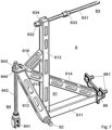
- the individual components of the second embodiment of the lifting device 4 are shown in Fig. 7 and Fig. 8 presented in detail.
- the lifting device 4 comprises two main components, a cantilever 5 and a structure 6 that can be moved thereon.
- a cantilever also known in the literature as a cantilever beam or cantilever arm
- the cantilever beam has a single support.
- the cantilever beam can generally be subjected to shear, bending and torsion, with the support fixing all six degrees of freedom (forces and moments).
- the horizontal beam is a support frame 51 and a mounting plate 56 at one end of the support frame serves as a support on the outer compressor housing 14.
- the compressor housing has fastening holes 141 distributed along the circumference for receiving the Fig. 1 shown fastening bolts 142.
- the fastening holes are recessed into a vertical surface of the outer compressor housing, so that a vertical stop is formed, which serves to fasten the inner compressor housing and, in the case of assembly/dismantling, the cantilever beam 5 of the lifting device 4 according to the invention.
- a mounting bracket 7 can be provided between the mounting plate 56 of the cantilever beam and the vertical stop of the compressor housing.
- the cantilever beam could also be mounted directly on the outer compressor housing
- the mounting bracket 7 is screwed onto the vertical stop of the outer compressor housing using fastening means 72, whereby the fastening holes 141 mentioned above are advantageously used.
- holes provided specifically for fastening the mounting bracket 7 could also be used.
- Fastening holes 71 are recessed into the mounting bracket 7 to accommodate fastening means 561 of the mounting plate 56 of the cantilever beam 5.
- the mounting plate of the cantilever beam could also be connected to the mounting bracket in another way, for example by means of a positive plug connection.
- the structure 6, the second component of the lifting device comprises a construction 61 made of profile rods, which serves to absorb and transmit forces to the cantilever beam.
- the basic task of the structure of the lifting device according to the invention is to grip the rotor block in order to move it along the extension of the support frame of the cantilever beam and relative to the housing.
- the structure 6 is placed on a carriage 53, which in turn can be moved on rails 52 along the support frame 51.
- the carriage 53 can be guided along the rails 52 of the cantilever beam by means of a trapezoidal thread spindle, which is optionally moved by hand or by cordless screwdriver via a spindle wheel 54 with a crank 541. This allows a continuous, slow movement of the structure and the rotor block attached to it.
- the structure itself could be guided directly along a rail on the cantilever beam, as long as the transmission of forces and moments is guaranteed. However, this does not result in any correction options with regard to the height and angular position of the rotor in relation to the housing.
- the structure according to the invention includes, in addition to the points of attack on the rotor block and the support on the slide, means for tilting the structure and for aligning the structure in relation to the rotor block 2.
- profile bars 61 comprises, in the simplest, first embodiment, an L-shaped basic framework formed from the two profile bars 611 and 613, which is supplemented by the threaded rod 631 of the fastening point 63 to form a C-shaped base support.
- This base support is fastened to two designated points on the rotor block, with the two fastening points are advantageously vertically spaced from one another.
- the two fastening points 63 and 66 are located above and below the compressor wheel at approximately the same radial height.
- a mounting plate is arranged on the free end of the profile rod 611, which can be fastened directly to the vertical stop 26 of the rotor block by means of fastening means 661.
- the threaded rod 631 is screwed directly into a corresponding hole 32 in the rotor block.
- the fastening points can either be arranged directly on the inner bearing housing 23 itself, or via a cover plate, which covers any unevenness, such as an existing guide device in the diffuser area.
- the openings for the fastening screws 31, with which the rotor block is fixed to the outer bearing housing 13, are used to accommodate the threaded rod 631 of the upper fastening point.
- the aforementioned C-shaped basic structure is equipped with a tilting rod 62 in the intersection area of the two profile rods 611 and 613, which is rotatably mounted in a receiving device 532 on the slide 53 of the cantilever beam 5.
- the tilting rod 62 used is secured against falling out in the receiving device 532 by a safety bolt during operation of the lifting device.
- the tilting rod allows a tilting movement of the construction made of profile rods 61 and the rotor block attached to it.
- a vertical fastening 64 of the structure 6 on the slide is provided at a distance from the tilting rod.
- the vertical fastening 64 essentially comprises a threaded rod 642 with a nut 643, a horizontal stop 644 with a hole for receiving the threaded rod and a connecting pin 641 attached to the threaded rod, which is arranged in a receiving device 531 provided for this purpose on the slide 53 and is also secured against falling out during operation.
- the hole for receiving the threaded rod in the horizontal stop 644 is arranged at a distance from the vertically running profile rod 613 of the base frame.
- the horizontal stop is directly connected to the base frame and in the second embodiment, for improved force transmission with heavier rotor blocks, it is firmly connected via several profile rods 612, 614, 615 and 616.
- the horizontal stop 644 which is spaced from the vertically running profile rod 613 of the base frame, can be positioned more or less far from the anchorage on the slide connecting pin 641 by turning the nut 643, whereby a corresponding adjustment of the extent of the tilting movement as well as a specific angular position of the construction made of profile bars 62 and the rotor block attached thereto with respect to the cantilever beam can be realized.
- the multiple profile bars 612, 614, 615 and 616 according to the second embodiment ensure increased stability of the structure 6, which can be advantageous for larger, heavier rotor blocks.
- the structure includes a second option for adjusting the angular position of the rotor block attached to the structure.
- the threaded rod 631 has a further nut 632 for adjusting the alignment of the structure with respect to the rotor block. This nut rests on a vertical stop 634.
- the rotor block can be adjusted in terms of height and angle when it is pulled out of the housing by turning the two nuts 632 and 643. Due to the high weight of the rotor, this is a great advantage, especially during installation, as otherwise there would be a risk that the rotor would rest at least partially on the housing and could be damaged.
- the rotor block is pressed out of the centering seat in the outer bearing housing using press-off screws 635.
- the press-off screws 635 provided for this purpose are screwed through the bore 32 until the seat length is in the range of two - in Fig. 3 indicated by way of example - coordinated seats 132 on the outer bearing housing 13 and 231 on the inner bearing housing 23.
- a freewheel is provided between a spindle nut 57 mounted on the threaded rod 55 and the slide 53.
- the spindle nut 57 is moved along the threaded rod by turning the threaded rod.
- the spindle nut has a groove-shaped freewheel area 571 in which a projection 533 of the slide is arranged so as to be freely movable between two axial stops.
- a spring 535 is axially mounted on the threaded rod between the spindle nut and an axial stop 534 of the slide. As soon as the spring 535 of the freewheel is fully compressed, the threaded rod 55 can be turned by turning the spindle wheel and the movable slide 53 is taken along.
Landscapes
- Engineering & Computer Science (AREA)
- General Engineering & Computer Science (AREA)
- Mechanical Engineering (AREA)
- Chemical & Material Sciences (AREA)
- Combustion & Propulsion (AREA)
- Supercharger (AREA)
- Load-Engaging Elements For Cranes (AREA)
Description
- Die Erfindung bezieht sich auf das Gebiet der Rotationsmaschinen. Sie betrifft eine Hebevorrichtung sowie ein Verfahren zum Verschieben eines Rotorblocks in einem Gehäuse entlang der Drehachse des im Rotorblock enthaltenen Rotors.
- Derartige Hebevorrichtungen werden als Montage/ Demontagewerkzeuge bei Abgasturboladern von aufgeladenen Brennkraftmaschinen oder vergleichbaren Rotationsmaschinen eingesetzt, bei welchen der Rotorblock ein Gewicht über hundert Kilogramm bis zu mehreren Tonnen aufweisen kann.
- Abgasturbolader werden zum Aufladen von grossen Brennkraftmaschinen eingesetzt. Diese treiben beispielsweise Meeresschiffe oder grosse Notstromaggregate an.
- Um den Abgasturbolader im Intervall von einigen tausend Arbeitsstunden zu warten, müssen die rotierenden Teile aus dem Gehäuse entnommen werden. Hierfür werden bei herkömmlichen Abgasturboladern die mehrteiligen Gehäuse entfernt und anschliessend der Rotor mithilfe eines Krans in axialer Richtung aus dem Gehäuse gehoben. Konkret wird zur Demontage eines Abgasturboladers in der Regel das Verdichtergehäuse entfernt, um mit einem Ausleger des Krans oberhalb des Schwerpunkts des Rotorblocks angreifen zu können.
- Der Rotorblock eines Abgasturboladers umfasst neben den rotierenden Teilen der Welle und der mit der Welle verbundenen Turbinen- und Verdichterräder auch die Lagerteile, also Axial- und Radiallager sowie innere Lagergehäuseteile. Dieser Rotorblock wird auch als Cartridge bezeichnet. Im Servicefall besteht die Möglichkeit, ein Cartridge eines Abgasturboladers vollständig auszutauschen. Dadurch verringert sich die Stillstandzeit des Abgasturboladers und damit der mittels des Abgasturboladers aufgeladenen Brennkraftmaschine. Weiter verringern lässt sich der Aufwand für den Ausbau und das Wiedereinsetzen des Cartridges, wenn möglichst wenige Gehäuseteile entfernt werden müssen. Beispielsweise wäre es wünschenswert, das äussere Verdichtergehäuse, welches mit seinem grossen Luftaustrittsstutzen fest in das Rohrsystem der Brennkraftmaschine integriert ist, genauso wie das gesamte Turbinengehäuse während den Wartungsarbeiten nicht abbauen zu müssen. Somit müsste lediglich das lufteintrittsseitige, innere Verdichtergehäuse entfernt werden, um den Rotorblock durch die dadurch freigegebene Axialöffnung aus dem Verdichtergehäuse und dem dahinterliegenden Lagergehäuse und Gasaustrittsgehäuse ziehen zu können.
- Verschiedene Vorrichtungen und Verfahren zum Ziehen und/ oder Einsetzen von Rotoren, Rotorblöcken oder Lagerbestandteilen aus einem Gehäuse sind im Stand der Technik beschrieben.
-
JP10-220399 -
US2011/0052426A1 offenbart eine Vorrichtung zur Demontage eines Rotors eines grossen Kompressors, welche eine beidseitige Abstützung des Rotors umfasst, wobei auf der Rückseite des Rotors Verlängerungselemente vorgesehen sind, um die Abstützung während des Herausschiebens des Rotors aus dem Gehäuse sicherzustellen. Die Vorrichtung umfasst weiter Schienenelemente, entlang deren der auszubauende Rotor verschoben werden kann. Insbesondere betrifft dieUS2011/0052426A1 ein Einführ-/Entnahmesystem für ein Kompressorgehäuse und ein Kompressorbündel. Das System umfasst ein Gerüst, das sich von einem ersten axialen Ende des Kompressorgehäuses erstreckt und so konfiguriert ist, dass es das Kompressorbündel während des Einsetzens stützt. Das System umfasst weiter eine Service-End-Rollenanordnung, die mit dem Kompressorbündel proximal zu einem axialen Ende des Kompressorbündels gekoppelt ist, wobei die Service-End-Rollenanordnung so konfiguriert ist, dass sie eine bewegliche Unterstützung für das Kompressorbündel auf dem Gerüst bereitstellt. - Die Aufgabe der vorliegenden Erfindung besteht darin, ein Werkzeug und ein Verfahren zu schaffen, welches den Ausbau eines Rotorblocks aus einem den Rotorblock umfassenden Gehäuse entlang der Drehachse des im Rotorblock enthaltenen Rotors ermöglicht.
- Ein Aspekt der Erfindung betrifft eine Hebevorrichtung gemäß dem unabhängigen Anspruch 1. Eine Hebevorrichtung umfasst einen Kragträger, der an einem Vertikalanschlag, also an einer axialen Stirnseite, des Gehäuses befestigt ist, und auf welchem ein entlang des Kragträgers verschiebbarer Aufbau angeordnet ist, welcher ebenfalls an einem Vertikalanschlag, also einer axialen Stirnseite des Rotorblocks befestigt ist.
- Die lineare Bewegung des Aufbaus auf dem Kragträger erfolgt durch Linearführungen (Schienen) und wird optional mit Kugellagern ausgestattet.
- Der Aufbau der Hebevorrichtung ist auf einem Schlitten angeordnet, wobei die Auflage des Aufbaus zweiteilig ist und eine Kippstange und eine vertikale Befestigung umfasst, wodurch sich der Aufbau bezüglich der Lage des Kragträgers neigen lässt.
- Optional kann als Antrieb der Verschiebung entlang des Kragträgers eine Trapezgewindespindel, die wahlweise per Hand oder Akkuschrauber bewegt wird vorgesehen sein.
- Optional kann über Gewindeschrauben die Höhe und Neigung des Rotorblocks justiert werden.
- Die erfindungsgemässe Hebevorrichtung weist keine weiteren Abstützungen auf und benötigt lediglich den Bauraum des Filterschalldämpfers. Insbesondere wird der Bauraum oberhalb des Gehäuses des Abgasturboladers während dem Ausbau und dem Wiedereinsetzen des Rotorblocks nicht benutzt, wodurch Isolationen, Rohrleitungen usw. nicht beeinträchtigt werden.
- Weitere Vorteile ergeben sich aus den abhängigen Ansprüchen.
- Ein weiterer Aspekt der Erfindung betrifft ein Verfahren gemäß dem unabhängigen Anspruch 9.
- Anschliessend sind anhand der Zeichnungen Ausführungsformen der erfindungsgemässen Hebevorrichtung erläutert. Hierbei zeigt
- Fig. 1
- eine schematische Darstellung eines entlang der Wellenachse (A) geführten Schnitts durch einen Abgasturbolader, wobei der Abgasturbolader einen in axialer Richtung zur Verdichterseite hin aus dem Gehäuse ausziehbaren Rotorblock umfasst,
- Fig. 2
- eine isometrische Ansicht eines Abgasturboladers nach
Fig. 1 mit aufgesetzter, erfindungsgemässer Hebevorrichtung gemäss einer ersten Ausführungsform und teilweise aus dem Gehäuse ausgezogenem Rotorblock, - Fig. 3
- eine schematische Darstellung eines entlang der Wellenachse geführten Schnitts durch den Abgasturbolader samt Hebevorrichtung nach
Fig. 2 , - Fig. 4
- eine schematische Darstellung eines vergrössert dargestellten Schnitts durch die Hebevorrichtung nach
Fig. 2 und3 , - Fig. 5
- eine seitliche Ansicht eines Abgasturboladers nach
Fig. 1 mit aufgesetzter, erfindungsgemässer Hebevorrichtung gemäss einer zweiten Ausführungsform und teilweise aus dem Gehäuse ausgezogenem Rotorblock , - Fig. 6
- eine schräge Ansicht der Anordnung nach
Fig. 5 , - Fig. 7
- eine isometrische Ansicht des Aufbaus der Hebevorrichtung, und
- Fig. 8
- eine isometrische Ansicht des Kragträgers der Hebevorrichtung und der Montagekonsole zur Befestigung des Kragträgers am Gehäuse eines Abgasturboladers. Weg zur Ausführung der Erfindung
-
Fig. 1 undFig. 2 zeigen einen Abgasturbolader wie er typischerweise zur Aufladung von grossen Brennkraftmaschinen eingesetzt wird. Er umfasst eine axial angeströmte Abgasturbine sowie einen Radialverdichter. - Das Gehäuse des Abgasturbolader setzt sich im wesentlichen aus fünf Gehäuseteilen zusammen. Axial in der Mitte ist das äussere Lagergehäuse 13 angeordnet. Das Lagergehäuse steht in der Regel auf einer Konsole welche an der Brennkraftmaschine angeordnet ist.
- Turbinenseitig ist am Lagergehäuse das Gasaustrittsgehäuse 12 und daran wiederum das Gaseintrittsgehäuse 11 befestigt. Das Gaseintrittsgehäuse 11 führt den heissen Abgasstrom vom Gaseintritt auf die Laufschaufeln des Turbinenrades 21, wobei der Strömungskanal durch das Gaseintrittsgehäuse von der Kreisrohrform am Gaseintritt in eine Ringrohrform im Anströmbereich der Turbinenschaufeln umgelenkt wird. Das Gasaustrittsgehäuse 12 weist einen grossen, spiralförmigen Sammelraum auf und mündet in den Gasaustritt, von wo aus die Abgase beispielsweise auf die Auspuffanlage oder eine nachgeschaltete, zweite Turbinenstufe geleitet werden.
- Verdichterseitig schliesst das äussere Verdichtergehäuse 14 ans äussere Lagergehäuse 13 an. Das äussere Verdichtergehäuse umfasst im wesentlichen einen spiralförmigen Sammelraum welcher in den Luftaustritt mündet. Der Luftaustritt des Verdichters ist ebenso wie turbinenseitig der Gaseintritt und der Gasaustritt dauerhaft an das Röhrensystem der Brennkraftmaschine angeschlossen und die jeweiligen Flanschbefestigungen sollten im Regelfall nicht gelöst werden müssen. Das fünfte Gehäuseteil, das innere Verdichtergehäuse, ist in den
Fig. 1 und2 nicht dargestellt. Das innere Verdichtergehäuse ist einerseits mittels der Befestigungsbolzen 142 am äusseren Verdichtergehäuse 14 befestigt, andererseits stellt es die Verbindung zum Lufteintritt dar. - Der Lufteintritt kann entweder durch einen aufgesetzten Filterschalldämpfer oder durch einen rohrförmigen Ansaugstutzen realisiert sein. Diese Verbindung ist im Servicefall die Einzige, welche regelmässig getrennt werden muss. Einerseits muss der Filterschalldämpfer selber regelmässig gewartet werden, andererseits bildet die durch das entfernte innere Verdichtergehäuse freigelegte Öffnung die Wartungsluke, durch welche der Rotorblock des Abgasturboladers aus dem Gehäuse gezogen werden kann.
- Wie die Darstellung erahnen lässt, befindet sich der Schwerpunkt des Rotorblocks 2, welcher neben dem eigentlichen Rotor mit Turbinenrad 21, Welle und Verdichterrad 22 auch den inneren Lagerbereich 23 umfasst, axial irgendwo im Bereich des Lagergehäuses. Um den Rotor mit einem direkt am Rotorblock angreifenden Kran aus der Gehäuseöffnung heben zu können, müsste somit das äussere Verdichtergehäuse 14 ebenfalls vom äusseren Lagergehäuse 13 demontiert werden. Dieser zusätzliche Aufwand soll mit dem nachfolgend beschriebenen, erfindungsgemässen Montage- und Demontagewerkzeug eingespart werden können.
-
Fig. 2 ,Fig. 3 undFig. 4 zeigen eine erste Ausführungsform der erfindungsgemässen Hebevorrichtung 4 im Einsatz.Fig. 5 undFig. 6 zeigen eine zweite Ausführungsform der erfindungsgemässen Hebevorrichtung 4 im Einsatz. Die einzelnen Bestandteile der zweiten Ausführungsform der Hebevorrichtung 4 sind inFig. 7 undFig. 8 im Detail dargestellt. - Die Hebevorrichtung 4 umfasst in beiden Ausführungsformen zwei Hauptbestandteile, einen Kragträger 5 (engl. Cantilever) sowie einen darauf verschiebbaren Aufbau 6. Ein Kragträger (in der Literatur auch als Kragbalken oder Kragarm bekannt) ist allgemein ein einseitig gelagerter, waagrechter Balken, welcher eine Last trägt. Der Kragbalken weist ein einziges Auflager auf. Der Kragbalken kann im allgemeinen auf Schub, Biegung und Torsion beansprucht werden, wobei das Auflager alle sechs Freiheitsgrade (Kräfte und Momente) fixiert. Im vorliegenden Fall des Kragträgers 5 der erfindungsgemässen Hebevorrichtung 4 ist der waagrechte Balken ein Tragrahmen 51 und eine Montageplatte 56 an einem Ende des Tragrahmens dient als Auflager am äusseren Verdichtergehäuse 14. Das Verdichtergehäuse weist entlang dem Umfang verteilt angeordnete Befestigungslöcher 141 zur Aufnahme der in
Fig. 1 gezeigten Befestigungsbolzen 142. Die Befestigungslöcher sind in eine Vertikalfläche des äusseren Verdichtergehäuses eingelassen, so dass sich ein Vertikalanschlag bildet, welcher zur Befestigung des inneren Verdichtergehäuses und, im Montage/ Demontagefall, des Kragbalkens 5 der erfindungsgemässen Hebevorrichtung 4 dient. - Zur vereinfachten Montierbarkeit des Kragbalkens am äusseren Verdichtergehäuse 14 und vor allem um die Portierbarkeit des Kragbalkens für Abgasturbolader verschiedener Baugrössen zu gewährleisten, kann eine Montagekonsole 7 zwischen der Montageplatte 56 des Kragträgers und dem Vertikalanschlag des Verdichtergehäuses vorgesehen sein. Optional könnte der Kragträger aber auch direkt auf das äussere Verdichtergehäuse geschraubt werden. Die Montagekonsole 7 wird mit Befestigungsmitteln 72 auf den Vertikalanschlag des äusseren Verdichtergehäuses geschraubt, wobei vorteilhafterweise die oben erwähnten Befestigungslöcher 141 genutzt werden. Optional könnten auch eigens dafür vorgesehene Löcher für die Befestigung der Montagekonsole 7 genutzt werden. In die Montagekonsole 7 sind Befestigungslöcher 71 zur Aufnahme von Befestigungsmitteln 561 der Montageplatte 56 des Kragbalkens 5 eingelassen. Optional könnte die Montageplatte des Kragbalkens auch auf andere Weise mit der Montagekonsole verbunden werden, beispielsweise durch eine formschlüssige Steckverbindung.
- Der Aufbau 6, das zweite Bestandteil der Hebevorrichtung, umfasst eine Konstruktion 61 aus Profilstangen, welche der Aufnahme und Übertragung von Kräften auf den Kragträger dient. Die Grundaufgabe des Aufbaus der erfindungsgemässen Hebevorrichtung besteht darin, den Rotorblock zu greifen um ihn entlang der Erstreckung des Tragrahmens des Kragträgers und relativ zum Gehäuse zu verschieben. Hierfür ist der Aufbau 6 auf einem Schlitten 53 aufgesetzt, welcher wiederum auf Schienen 52 entlang des Tragrahmens 51 verschiebbar ist. Optional kann der Schlitten 53 mittels einer Trapezgewindespindel, die wahlweise über ein Spindelrad 54 mit einer Kurbel 541 per Hand oder per Akkuschrauber bewegt wird, entlang der Schienen 52 des Kragträgers geführt werden. Dies erlaubt eine kontinuierliche, langsame Verschiebung des Aufbaus und des daran befestigten Rotorblocks.
- In einer einfachen Form könnte der Aufbau selber direkt entlang einer Schiene am Kragträger geführt sein, solange die Übertragung der Kräfte und Momente gewährleistet ist. Allerdings ergeben sich dadurch keinerlei Korrekturmöglichkeiten bezüglich der Höhe und der Winkellage des Rotors bezüglich des Gehäuses. Um genau diesem Punkt gerecht zu werden, umfasst der erfindungsgemässe Aufbau neben den Angriffsstellen am Rotorblock und der Auflage am Schlitten auch Mittel zum Kippen der Konstruktion und zum Ausrichten der Konstruktion bezüglich des Rotorblocks 2.
- Die dargestellte Konstruktion aus Profilstangen 61 umfasst in der einfachsten, ersten Ausführungsform ein aus den beiden Profilstangen 611 und 613 gebildetes, L-förmiges Grundgerüst, welches durch die Gewindestange 631 der Befestigungsstelle 63 zu einem C-förmigen Grundträger ergänzt wird. Dieser Grundträger wird an zwei dafür vorgesehenen Stellen des Rotorblocks befestigt, wobei die beiden Befestigungsstellen vorteilhafterweise vertikal voneinander beabstandet sind. Im vorliegenden Fall befinden sich die beiden Befestigungsstellen 63 und 66 oberhalb und unterhalb des Verdichterrades auf etwa gleicher radialer Höhe. Im Bereich der unteren Befestigungsstelle ist eine Montageplatte am freien Ende der Profilstange 611 angeordnet, welche mittels Befestigungsmittel 661 direkt am Vertikalanschlag 26 des Rotorblocks befestigt werden kann. Im Bereich der oberen Befestigungsstelle ist die Gewindestange 631 direkt in eine entsprechende Bohrung 32 im Rotorblock eingeschraubt. Am Rotorblock können die Befestigungsstellen entweder direkt am inneren Lagergehäuse 23 selber angeordnet sein, oder, über eine Abdeckplatte, welche allfällige Unebenheiten, wie beispielsweise eine vorhandene Leitvorrichtung im Diffusorbereich überdeckt. Die Öffnungen für die Befestigungsschrauben 31, mit welchen der Rotorblock am äusseren Lagergehäuse 13 fixiert ist, werden für die Aufnahme der Gewindestange 631 der oberen Befestigungsstelle verwendet. Das erwähnte C-förmige Grundgerüst ist im Schnittbereich der beiden Profilstangen 611 und 613 mit einer Kippstange 62 ausgestattet, welche in einer Aufnahmevorrichtung 532 auf dem Schlitten 53 des Kragträgers 5 drehbar gelagert ist. Die eingesetzte Kippstange 62 wird in der Aufnahmevorrichtung 532 im Betrieb der Hebevorrichtung durch einen Sicherungsbolzen gegen Herausfallen gesichert. Die Kippstange erlaubt eine Kippbewegung der Konstruktion aus Profilstangen 61 und des daran befestigten Rotorblocks. Um das Ausmass der Kippbewegung auf eine bestimmte Winkellage einstellen zu können ist beabstandet von der Kippstange eine vertikale Befestigung 64 des Aufbaus 6 am Schlitten vorgesehen. Die vertikale Befestigung 64 umfasst als Einstellmittel im wesentlichen eine Gewindestange 642 mit einer Mutter 643, einen Horizontalanschlag 644 mit einem Loch zur Aufnahme der Gewindestange sowie einen an der Gewindestange angebrachten Verbindungsstift 641, welcher in einer dafür vorgesehenen Aufnahmevorrichtung 531 am Schlitten 53 angeordnet und ebenfalls im Betrieb gegen herausfallen gesichert ist. Das Loch zur Aufnahme der Gewindestange im Horizontalanschlag 644 ist beabstandet von der vertikal verlaufenden Profilstange 613 des Grundgerüsts angeordnet. Der Horizontalanschlag ist in der ersten Ausführungsform direkt und in der zweiten Ausführungsform, zur verbesserten Kräfteübertragung bei schwereren Rotorblöcken über mehrere Profilstangen 612, 614, 615 und 616 fest mit dem Grundgerüst verbunden. Der von der vertikal verlaufenden Profilstange 613 des Grundgerüsts beabstandete Horizontalanschlag 644 kann mittels Drehen der Mutter 643 mehr oder weniger weit von der Verankerung am Schlitten Verbindungsstift 641 positioniert werden, wodurch sich eine entsprechende Einstellung des Ausmasses der Kippbewegung sowie eine bestimmte Winkellage der Konstruktion aus Profilstangen 62 und des daran befestigten Rotorblocks bezüglich des Kragträgers realisieren lässt. Die mehreren Profilstangen 612, 614, 615 und 616 gemäss der zweiten Ausführungsform sorgen für eine erhöhte Stabilität des Aufbaus 6, welche etwa bei grösseren, schwereren Rotorblöcken von Vorteil sein kann.
- Im Bereich der oberen Befestigungsstelle umfasst der Aufbau eine zweite Möglichkeit die Winkellage des am Aufbau befestigten Rotorblocks einzustellen. Die Gewindestange 631 weist neben der Kontermutter 633 zum Einschrauben der Gewindestange 631 in den Rotorblock 2 eine weitere Mutter 632 zur Einstellung der Ausrichtung des Aufbaus bezüglich des Rotorblocks auf. Diese Mutter liegt an einem Vertikalanschlag 634 an. Durch Drehen an der Mutter 632 auf der Gewindestange 631 kann der axiale Abstand zwischen dem Vertikalanschlag 634 und dem Rotorblock eingestellt werden. Verändert sich dieser Abstand hat dies einen Einfluss auf die Winkellage des Rotorblocks bezüglich der Konstruktion aus Profilstangen. Werden die beiden Einstellmöglichkeiten überlagert, ergibt sich die Möglichkeit, den Rotorblock in der Höhe anzuheben, in Ergänzung der Möglichkeit der Anpassung der Winkellage. Ein Kippen der Konstruktion aus Profilstangen 61 um die Achse der Kippstange 62 führt zu einer Veränderten Winkellage des am Aufbau befestigten Rotorblocks. Durch Veränderung des Abstandes zwischen dem Vertikalanschlag 634 und dem Rotorblock lässt sich die veränderte Winkellage wieder korrigieren, wobei dadurch eine Höhenverstellung resultiert.
- Somit lässt sich der Rotorblock beim Herausziehen aus dem Gehäuse durch Drehen an den beiden Muttern 632 beziehungsweise 643 bezüglich der Höhe und der Winkellage justieren. Aufgrund des hohen Gewichts des Rotors ist dies insbesondere beim Einbau ein grosser Vorteil, da sonst die Gefahr bestehen würde, dass der Rotor zumindest teilweise am Gehäuse aufliegt und es zu Beschädigungen kommen könnte.
- Im Demontagefall wird mittels Abpress-Schrauben 635 der Rotorblock aus dem Zentriersitz im äusseren Lagergehäuse herausgedrückt (abgepresst). Hierfür werden die speziell dafür vorgesehenen Abpress-Schrauben 635 soweit durch die Bohrung 32 hindurch geschraubt, bis die Sitzlänge im Bereich zweier - in
Fig. 3 beispielhaft angedeuteten - aufeinander abgestimmten Sitze 132 am äusseren Lagergehäuse 13 und 231 am inneren Lagergehäuse 23 überwunden ist. - Damit diese axiale Verschiebung bei bereits montierter Hebevorrichtung erfolgen kann, ist für diese erwähnte Sitzlänge wie in
Fig. 4 im Detail dargestellt ist ein Freilauf zwischen einer auf der Gewindestange 55 montierten Spindelmutter 57 und dem Schlitten 53 vorgesehen. Die Spindelmutter 57 wird durch Drehen der Gewindestange entlang der Gewindestange bewegt. Die Spindelmutter weist einen nutförmigen Freilaufbereich 571 auf, in welchem ein Vorsprung 533 des Schlittens zwischen zwei Axialanschlägen frei beweglich angeordnet ist. Zur Dämpfung der innerhalb der Axialanschlägen möglichen, freien Bewegung des Schlittens bezüglich der Spindelmutter 57 ist axial zwischen der Spindelmutter und einem Axialanschlag 534 des Schlittens eine Feder 535 auf die Gewindestange aufgezogen. Sobald die Feder 535 des Freilaufs vollständig zusammengedrückt ist, kann mittels Drehen des Spindelrades die Gewindestange 55 gedreht werden und der bewegliche Schlitten 53 wird mitgenommen. -
- 11
- Gaseintrittsgehäuse der Abgasturbine
- 12
- Gasaustrittsgehäuse der Abgasturbine
- 13
- Äusseres Lagergehäuse
- 132
- Zentriersitz am äusseren Lagergehäuse
- 14
- Äusseres Verdichtergehäuse
- 141
- Befestigungslöcher
- 142
- Befestigungsbolzen
- 2
- Rotorblock
- 21
- Turbinenrad
- 22
- Verdichterrad
- 23
- Inneres Lagergehäuse
- 231
- Zentriersitz am inneren Lagergehäuse
- 25
- Abdeckung für Verdichterrad
- 26
- Vertikalanschlag mit Löchern zur Aufnahme von Befestigungsmittel
- 31
- Befestigungsmittel zum Befestigen des Rotorblocks am Lagergehäuse
- 32
- Bohrung im Rotorblock
- 4
- Hebevorrichtung (umfassend 5 und 6)
- 5
- Kragträger der Hebevorrichtung, umfassend:
- 51
- Tragrahmen
- 52
- Schiene
- 53
- Schlitten
- 531
- Aufnahmevorrichtung für vertikale Befestigung des Aufbaus
- 532
- Aufnahmevorrichtung für die Kippstange des Aufbaus
- 533
- Vorsprung am Schlitten zur Führung im Freilaufbereich der Spindelmutter 57
- 534
- Axialanschlag am Schlitten
- 535
- Feder
- 54
- Spindelrad
- 541
- Kurbel
- 55
- Gewindestange (Spindel)
- 56
- Montageplatte des Kragträgers zur Befestigung an der Montagekonsole
- 561
- Befestigungsmittel
- 57
- Spindelmutter
- 571
- Nutförmiger Freilaufbereich
- 6
- Aufbau der Hebevorrichtung, umfassend:
- 61
- Konstruktion aus Profilstangen (611, 612, 613, 614, 615, 616)
- 62
- Kippstange des Aufbaus
- 63
- Befestigungsstelle (horizontale Befestigung des Aufbaus)
- 631
- Gewindestange
- 632
- Mutter zur Einstellung der Ausrichtung des Rotorblocks bezüglich der Konstruktion aus Profilstangen
- 633
- Kontermutter zum Einschrauben der Gewindestange in den Rotorblock
- 634
- Vertikalanschlag
- 635
- Abpress-Schraube
- 64
- Vertikale Befestigung des Aufbaus
- 641
- Verbindungsstift zur vertikalen Befestigung des Aufbaus am Kragträger
- 642
- Gewindestange
- 644
- Horizontalanschlag
- 643
- Mutter zur Einstellung der Ausrichtung der Konstruktion aus Profilstangen bezüglich des Kragträgers
- 66
- Befestigungsstelle (Montageplatte des Aufbaus zur Befestigung am Rotorblock)
- 661
- Befestigungsmittel
- 7
- Montagekonsole
- 71
- Löcher in der Montagekonsole zur Aufnahme von Befestigungsmitteln
- 72
- Befestigungsmittel
Claims (9)
- Hebevorrichtung (4) zum Verschieben eines in einem Gehäuse eines Abgasturboladers angeordneten Rotorblocks (2) entlang der Drehachse (A) des im Rotorblock (2) enthaltenen Rotors, umfassendeinen Kragträger (5), welcher zur Befestigung an einem Vertikalanschlag eines den Rotorblock (2) umgebenden Gehäuses vorgesehen ist, wobei der Kragträger (5) einen Tragrahmen (51) mit darauf angeordneten Schienen (52) sowie einen auf den Schienen (52) geführten Schlitten (53) umfasst, undeinen Aufbau (6), welcher auf dem Schlitten (53) angeordnet ist, wobei der Aufbau (6) zumindest zwei vertikal beabstandete Befestigungsstellen (63, 66) zur Befestigung des Aufbaus (6) an dem mittels der Hebevorrichtung (4) in dem Gehäuse entlang der axialen Richtung zu verschiebenden Rotorblock (2) umfasst, und wobei die mindestens zwei Befestigungsstellen (63, 66) über einen C-förmigen Grundträger mit dem Schlitten (53) verbunden sind,wobei eine Auflage des Aufbaus (6) zweiteilig ist und eine Kippstange (62) und eine vertikale Befestigung (64) umfasst, wobei eine Achse der Kippstange (62) senkrecht zu einer Längsachse des Kragträgers und horizontal ausgerichtet ist, und wobei die vertikale Befestigung (64) Mittel zum Einstellen der Ausrichtung des Aufbaus (6) bezüglich des Kragträgers (5) umfasst, so dass die Winkellage des Aufbaus (6) um die Achse der Kippstange (62) einstellbar ist,wobei am Schlitten (53) Aufnahmevorrichtungen (531, 532) zur Befestigung des an einem Vertikalanschlag (26) des Rotorblocks (2) befestigbaren Aufbaus (6) am Schlitten (53) angeordnet sind, so dass der Aufbau (6) mithilfe des Schlittens (53) entlang der auf dem Tragrahmen (51) des Kragträgers (5) angeordneten Schienen (52) verschiebbar ist,wobei die zumindest zwei vertikal beabstandeten Befestigungsstellen (63, 66) über den C-förmigen Grundträger mit der Kippstange (62) und der vertikalen Befestigung (64) verbunden sind, wobei diese je unterschiedlich weit von den zumindest zwei vertikal beabstandeten Befestigungsstellen (63, 66) horizontal beabstandet angeordnet sind, wobei der Aufbau (6) mittels der Kippstange (62) und der vertikalen Befestigung (64) an den ebenfalls horizontal voneinander beabstandeten Aufnahmevorrichtungen (531, 532) des Schlittens (53) befestigt ist, und wobei ein Einstellmittel der vertikalen Befestigung (64) direkt oder indirekt fest mit dem C-förmigen Grundträger verbunden ist.
- Hebevorrichtung (4) nach Anspruch 1, weiter umfassend eine Gewindestange (55), wobei der Schlitten (53) mit einer Spindelmutter (57) verbunden ist, welche auf der Gewindestange (55) angeordnet ist, so dass durch Drehen der Gewindestange (55) sich die Spindelmutter (57) und somit der Schlitten (53) entlang der Gewindestange (55) bewegen lassen, wobei zum Drehen der Gewindestange (55) vorzugsweise ein Spindelrad (54) vorgesehen ist.
- Hebevorrichtung (4) nach Anspruch 2, wobei zwischen Spindelmutter (57) und dem Schlitten (53) eine Verbindung mit Spiel in Richtung der Gewindestange (55) vorgesehen ist, so dass sich der Schlitten (53) im Rahmen des Spiels relativ zur Spindelmutter (57) entlang der Gewindestange (55) bewegen lässt, auch wenn die Gewindestange (55) nicht gedreht wird.
- Hebevorrichtung (4) nach einem der Ansprüche 1 bis 3, wobei die mindestens zwei Befestigungsstellen (63, 66) über Profilstangen (611, ..., 616) des C-förmigen Grundträgers mit dem Schlitten (53) verbunden sind.
- Hebevorrichtung (4) nach Anspruch 4, wobei die zumindest zwei vertikal beabstandeten Befestigungsstellen (63, 66) über die Profilstangen (611, ..., 616) mit der Kippstange (62) und der vertikalen Befestigung (64) verbunden sind.
- Hebevorrichtung (4) nach einem der Ansprüche 4 oder 5, wobei mindestens eine der zumindest zwei vertikal beabstandeten Befestigungsstellen (63, 66) Mittel zum Einstellen der Ausrichtung des Aufbaus (6) bezüglich eines am Aufbau (6) befestigten Rotorblocks (2) umfasst, wobei diese Mittel vorzugsweise eine Gewindestange (631) und eine Mutter (632) umfassen.
- Hebevorrichtung (4) nach einem der Ansprüche 4 bis 6, wobei die Mittel zum Einstellen der Winkellage des Aufbaus (6) eine Gewindestange (642) und eine Mutter (643) umfassen, und mittels der Mutter (643) und der Gewindestange (642) die Winkellage des Aufbaus (6) um die Achse der Kippstange (62) eingestellt werden kann.
- Hebevorrichtung (4) nach einem der Ansprüche 1 bis 7, wobei zur Befestigung des Kragträgers (5) an einem Vertikalanschlag des Gehäuses eine Montagekonsole (7) vorgesehen ist.
- Verfahren zum Verschieben eines in einem Gehäuse eines Abgasturboladers angeordneten Rotorblocks (2) entlang der Drehachse (A) des im Rotorblock (2) enthaltenen Rotors in ebendiesem Gehäuse mittels einer Hebevorrichtung (4) nach einem der Ansprüche 1 bis 8, umfassend die folgenden Schritte:- Befestigen des Kragträgers (5) der Hebevorrichtung (4) an einem Vertikalanschlag des Gehäuses,- Befestigen des Aufbaus (6) der Hebevorrichtung (4) an dem Rotorblock (2),- Verschieben des Aufbaus (6) entlang des Kragträgers (5).
Priority Applications (1)
| Application Number | Priority Date | Filing Date | Title |
|---|---|---|---|
| EP14711990.3A EP2978942B1 (de) | 2013-03-28 | 2014-03-25 | Kragträgerschlitten für montage und demontage eines rotorblocks |
Applications Claiming Priority (3)
| Application Number | Priority Date | Filing Date | Title |
|---|---|---|---|
| EP13161751 | 2013-03-28 | ||
| PCT/EP2014/055914 WO2014154663A1 (de) | 2013-03-28 | 2014-03-25 | Kragträgerschlitten für montage und demontage eines rotorblocks |
| EP14711990.3A EP2978942B1 (de) | 2013-03-28 | 2014-03-25 | Kragträgerschlitten für montage und demontage eines rotorblocks |
Publications (2)
| Publication Number | Publication Date |
|---|---|
| EP2978942A1 EP2978942A1 (de) | 2016-02-03 |
| EP2978942B1 true EP2978942B1 (de) | 2025-02-19 |
Family
ID=48044650
Family Applications (1)
| Application Number | Title | Priority Date | Filing Date |
|---|---|---|---|
| EP14711990.3A Active EP2978942B1 (de) | 2013-03-28 | 2014-03-25 | Kragträgerschlitten für montage und demontage eines rotorblocks |
Country Status (10)
| Country | Link |
|---|---|
| US (1) | US9896973B2 (de) |
| EP (1) | EP2978942B1 (de) |
| JP (1) | JP6341990B2 (de) |
| KR (1) | KR102191182B1 (de) |
| CN (1) | CN105189939B (de) |
| BR (1) | BR112015018490B1 (de) |
| ES (1) | ES3022632T3 (de) |
| FI (1) | FI2978942T3 (de) |
| SG (2) | SG11201506460YA (de) |
| WO (1) | WO2014154663A1 (de) |
Families Citing this family (6)
| Publication number | Priority date | Publication date | Assignee | Title |
|---|---|---|---|---|
| FR3038382B1 (fr) * | 2015-07-01 | 2017-07-07 | Snecma | Outillage pour l'equilibrage d'un module de turbomachine |
| US10221724B2 (en) * | 2015-10-15 | 2019-03-05 | United Technologies Corporation | Horizontal engine build stand |
| DE102016217980A1 (de) | 2016-09-20 | 2018-03-22 | Siemens Aktiengesellschaft | Vorrichtung zum Einbauen und Ausbauen eines Bauteils einer Gasturbine |
| EP3808945A1 (de) * | 2019-10-16 | 2021-04-21 | ABB Schweiz AG | Montage-/demontagevorrichtung für einen oder mehrere rotorblöcke einer turboladeranordnung |
| GB201917397D0 (en) | 2019-11-29 | 2020-01-15 | Siemens Ag | Method of assembling and disassembling a gas turbine engine module and an assembly therefor |
| US11517987B1 (en) * | 2021-10-19 | 2022-12-06 | Dresser, Llc | Installing trim in a valve assembly |
Citations (2)
| Publication number | Priority date | Publication date | Assignee | Title |
|---|---|---|---|---|
| DE2146995B2 (de) * | 1971-09-21 | 1974-04-18 | Maschinenfabrik Hilma Gmbh, 5912 Hilchenbach | Schraubstock |
| EP0460457B1 (de) * | 1990-06-07 | 1995-03-15 | Franz Arnold | Maschinenschraubstock |
Family Cites Families (23)
| Publication number | Priority date | Publication date | Assignee | Title |
|---|---|---|---|---|
| NL87380C (de) * | 1950-03-27 | |||
| US4157613A (en) * | 1977-12-23 | 1979-06-12 | D. A. Griffin Corp. | Apparatus for inserting a rotor into a stator |
| US4451979A (en) * | 1980-10-27 | 1984-06-05 | Elliott Turbomachinery Company, Inc. | Assembly and disassembly apparatus for use with a rotary machine |
| US4532689A (en) * | 1982-09-29 | 1985-08-06 | John Harder & Co. | Machine for removing electric traction motors from wheel spindles |
| US4590653A (en) * | 1983-05-04 | 1986-05-27 | General Electric Company | Turbine rotor heating, disassembly, handling and reassembly method and apparatus |
| US4635336A (en) * | 1983-05-04 | 1987-01-13 | General Electric Company | Turbine rotor heating, disassembly, handling and reassembly method and apparatus |
| US5313696A (en) * | 1993-09-17 | 1994-05-24 | Cae Machinery Ltd. | Method and apparatus for removing blade ring in a ring flaker |
| DE19640647A1 (de) * | 1996-10-02 | 1998-04-09 | Asea Brown Boveri | Verdichterradanordnung für Turbolader |
| JP3752038B2 (ja) * | 1997-02-03 | 2006-03-08 | 三菱重工業株式会社 | ポンプの内部部材抜き出し、組み込み装置及び方法 |
| JPH10231737A (ja) * | 1997-02-18 | 1998-09-02 | Tokyo Electric Power Co Inc:The | ガスタービン燃焼器分解・組立支援装置 |
| US6279309B1 (en) * | 1998-09-24 | 2001-08-28 | Ramgen Power Systems, Inc. | Modular multi-part rail mounted engine assembly |
| US20030014961A1 (en) * | 2001-07-23 | 2003-01-23 | Ramgen Power Systems, Inc. | Compact rotary ramjet engine with rapidly interchangeable cartridge containing hot section rotating elements |
| DE10215409B4 (de) * | 2002-04-08 | 2004-11-11 | Audi Ag | Vorrichtung zum Transport einer Brennkraftmaschine |
| CA2480376C (en) * | 2003-09-04 | 2013-04-09 | Justoy Pty Ltd | Article handling apparatus |
| DE102005052077B4 (de) * | 2005-10-28 | 2016-11-24 | Man Diesel & Turbo Se | Vorrichtung zur seitlichen Montage und Demontage eines Kompressorbarrels |
| EP2045472A1 (de) * | 2007-10-05 | 2009-04-08 | Siemens Aktiengesellschaft | Verfahren zur Montage grosser Turbomaschinen und Vorrichtung zur Durchführung desselben |
| US8544579B2 (en) * | 2008-05-13 | 2013-10-01 | Caterpillar Inc. | Axle assembly for electric drive machine |
| US8534986B2 (en) | 2009-08-26 | 2013-09-17 | Dresser-Rand Company | Bundle insertion/extraction system and method |
| US8713776B2 (en) * | 2010-04-07 | 2014-05-06 | General Electric Company | System and tool for installing combustion liners |
| JP5550584B2 (ja) | 2011-02-25 | 2014-07-16 | 三菱重工コンプレッサ株式会社 | 圧縮機、この挿脱装置およびこの挿脱方法 |
| CN202370911U (zh) | 2011-12-23 | 2012-08-08 | 沈阳透平机械股份有限公司 | 一种垂直剖分离心压缩机机芯拆装工具 |
| EP2610439A1 (de) * | 2011-12-30 | 2013-07-03 | Siemens Aktiengesellschaft | Verfahren zum Ziehen und/oder Einsetzen eines Turbinenlagers sowie Vorrichtung zur Durchführung des Verfahrens |
| US8826520B1 (en) * | 2012-07-26 | 2014-09-09 | General Electric Company | Apparatus for extracting a rotor from a generator |
-
2014
- 2014-03-25 KR KR1020157022711A patent/KR102191182B1/ko active Active
- 2014-03-25 JP JP2016504627A patent/JP6341990B2/ja active Active
- 2014-03-25 ES ES14711990T patent/ES3022632T3/es active Active
- 2014-03-25 SG SG11201506460YA patent/SG11201506460YA/en unknown
- 2014-03-25 WO PCT/EP2014/055914 patent/WO2014154663A1/de not_active Ceased
- 2014-03-25 SG SG10201708361RA patent/SG10201708361RA/en unknown
- 2014-03-25 CN CN201480019058.9A patent/CN105189939B/zh active Active
- 2014-03-25 BR BR112015018490-1A patent/BR112015018490B1/pt active IP Right Grant
- 2014-03-25 EP EP14711990.3A patent/EP2978942B1/de active Active
- 2014-03-25 FI FIEP14711990.3T patent/FI2978942T3/fi active
-
2015
- 2015-09-24 US US14/864,503 patent/US9896973B2/en active Active
Patent Citations (2)
| Publication number | Priority date | Publication date | Assignee | Title |
|---|---|---|---|---|
| DE2146995B2 (de) * | 1971-09-21 | 1974-04-18 | Maschinenfabrik Hilma Gmbh, 5912 Hilchenbach | Schraubstock |
| EP0460457B1 (de) * | 1990-06-07 | 1995-03-15 | Franz Arnold | Maschinenschraubstock |
Also Published As
| Publication number | Publication date |
|---|---|
| JP2016517918A (ja) | 2016-06-20 |
| BR112015018490A2 (pt) | 2017-07-18 |
| US9896973B2 (en) | 2018-02-20 |
| EP2978942A1 (de) | 2016-02-03 |
| KR102191182B1 (ko) | 2020-12-16 |
| US20160010504A1 (en) | 2016-01-14 |
| BR112015018490B1 (pt) | 2023-04-11 |
| JP6341990B2 (ja) | 2018-06-13 |
| ES3022632T3 (en) | 2025-05-28 |
| SG11201506460YA (en) | 2015-10-29 |
| CN105189939B (zh) | 2016-11-30 |
| WO2014154663A1 (de) | 2014-10-02 |
| KR20150133703A (ko) | 2015-11-30 |
| SG10201708361RA (en) | 2017-11-29 |
| CN105189939A (zh) | 2015-12-23 |
| FI2978942T3 (fi) | 2025-05-15 |
Similar Documents
| Publication | Publication Date | Title |
|---|---|---|
| EP2798163B1 (de) | Verfahren zum ziehen und/oder einsetzen eines turbinenlagers sowie vorrichtung zur durchführung des verfahrens | |
| DE102005052077B4 (de) | Vorrichtung zur seitlichen Montage und Demontage eines Kompressorbarrels | |
| DE102010062418B9 (de) | Verfahren und Vorrichtung zum Verdrehen eines Roboterblattlagers an Windenergieanlagen ohne Einsatz eines Autokranes | |
| EP2655808B1 (de) | Verfahren zum abziehen eines lagerkörpers vom rotor einer gasturbine sowie rohrförmige wellenverlängerung | |
| WO2014154663A1 (de) | Kragträgerschlitten für montage und demontage eines rotorblocks | |
| EP2134928B1 (de) | Montagevorrichtung zum zusammensetzen und zerlegen eines sich aus rotorscheiben zusammensetzenden rotors einer strömungsmaschine | |
| EP2236939A1 (de) | Vorrichtung zur Montage und Demontage eines Bauteils einer Gasturbine | |
| EP2407646A1 (de) | Verfahren und Vorrichtung zur Einstellung der Rotorlage bei einer Gasturbine oder Dampfturbine | |
| EP3538745B1 (de) | Verfahren zur montage und/oder demontage von komponenten einer ein turbinengehäuse aufweisenden turbine sowie adapter und system zur verwendung in dem verfahren | |
| WO2009118036A1 (de) | Turbinenrotor für eine gasturbine | |
| EP3574166B1 (de) | Rotorblattbefahranlage und verfahren zur positionierung der wartungskammer einer rotorblattbefahranlage | |
| EP3475538B1 (de) | Vorrichtung zum einbauen und ausbauen eines bauteils einer gasturbine | |
| EP3839252B1 (de) | Montagevorrichtung für rotorblätter einer windenergieanlage | |
| EP0887536B1 (de) | Verfahren zur Inspektion einer Lagerschale und Verfahren zum Ausbau einer Schubstange bei Grossdieselmotoren, Werkzeugsatz hierfür, sowie Grossdieselmotor mit eingebautem Werkzeugsatz | |
| WO2021074008A1 (de) | Montage-/demontagevorrichtung für einen oder mehrere rotorblöcke einer turboladerandordnung, sowie verfahren | |
| DE102010064637B3 (de) | Verfahren zur Instandhaltung einer Windenergieanlage, Zwischenstück und Verfahren zur Verwendung mindestens eines solchen Zwischenstücks | |
| CH712345B1 (de) | Vorrichtung mit einer Halteeinrichtung für die Positionierung einer Schraubenmutter einer Schraubenverbindung bei Überkopfmontage. | |
| WO2014040765A1 (de) | Wasserturbine | |
| DE102008004715A1 (de) | Verfahren zum Montieren eines Azimut-Gleitlager-Systems | |
| WO2024245766A1 (de) | Befestigungsvorrichtung zur befestigung einer turbomaschine | |
| DE202022102907U1 (de) | Vorrichtung zur Fixierung der Stellung von verstellbaren Leitschaufelreihen eines Turbokompressors | |
| DE672772C (de) | Verfahren zum Einbau von Motoren elektrischer Triebfahrzeuge | |
| DE102016119232A1 (de) | Abgasturbolader für eine Verbrennungskraftmaschine |
Legal Events
| Date | Code | Title | Description |
|---|---|---|---|
| PUAI | Public reference made under article 153(3) epc to a published international application that has entered the european phase |
Free format text: ORIGINAL CODE: 0009012 |
|
| 17P | Request for examination filed |
Effective date: 20151014 |
|
| AK | Designated contracting states |
Kind code of ref document: A1 Designated state(s): AL AT BE BG CH CY CZ DE DK EE ES FI FR GB GR HR HU IE IS IT LI LT LU LV MC MK MT NL NO PL PT RO RS SE SI SK SM TR |
|
| AX | Request for extension of the european patent |
Extension state: BA ME |
|
| DAX | Request for extension of the european patent (deleted) | ||
| STAA | Information on the status of an ep patent application or granted ep patent |
Free format text: STATUS: EXAMINATION IS IN PROGRESS |
|
| 17Q | First examination report despatched |
Effective date: 20190314 |
|
| RAP1 | Party data changed (applicant data changed or rights of an application transferred) |
Owner name: ABB SCHWEIZ AG |
|
| RAP1 | Party data changed (applicant data changed or rights of an application transferred) |
Owner name: ABB SCHWEIZ AG |
|
| RAP1 | Party data changed (applicant data changed or rights of an application transferred) |
Owner name: TURBO SYSTEMS SWITZERLAND LTD. |
|
| GRAP | Despatch of communication of intention to grant a patent |
Free format text: ORIGINAL CODE: EPIDOSNIGR1 |
|
| STAA | Information on the status of an ep patent application or granted ep patent |
Free format text: STATUS: GRANT OF PATENT IS INTENDED |
|
| INTG | Intention to grant announced |
Effective date: 20240918 |
|
| RAP3 | Party data changed (applicant data changed or rights of an application transferred) |
Owner name: ACCELLERON SWITZERLAND LTD. |
|
| GRAS | Grant fee paid |
Free format text: ORIGINAL CODE: EPIDOSNIGR3 |
|
| GRAA | (expected) grant |
Free format text: ORIGINAL CODE: 0009210 |
|
| STAA | Information on the status of an ep patent application or granted ep patent |
Free format text: STATUS: THE PATENT HAS BEEN GRANTED |
|
| RIN1 | Information on inventor provided before grant (corrected) |
Inventor name: LANNI, FABRIZIO Inventor name: BAUMGARTNER, HANS Inventor name: RODER, RUDOLF Inventor name: PROBST, REINER Inventor name: JARUSEL, MATTHIAS |
|
| AK | Designated contracting states |
Kind code of ref document: B1 Designated state(s): AL AT BE BG CH CY CZ DE DK EE ES FI FR GB GR HR HU IE IS IT LI LT LU LV MC MK MT NL NO PL PT RO RS SE SI SK SM TR |
|
| REG | Reference to a national code |
Ref country code: GB Ref legal event code: FG4D Free format text: NOT ENGLISH |
|
| REG | Reference to a national code |
Ref country code: CH Ref legal event code: EP |
|
| REG | Reference to a national code |
Ref country code: IE Ref legal event code: FG4D Free format text: LANGUAGE OF EP DOCUMENT: GERMAN |
|
| REG | Reference to a national code |
Ref country code: DE Ref legal event code: R096 Ref document number: 502014016906 Country of ref document: DE |
|
| REG | Reference to a national code |
Ref country code: NL Ref legal event code: FP |
|
| REG | Reference to a national code |
Ref country code: FI Ref legal event code: FGE |
|
| REG | Reference to a national code |
Ref country code: ES Ref legal event code: FG2A Ref document number: 3022632 Country of ref document: ES Kind code of ref document: T3 Effective date: 20250528 |
|
| REG | Reference to a national code |
Ref country code: GR Ref legal event code: EP Ref document number: 20250400823 Country of ref document: GR Effective date: 20250514 |
|
| PG25 | Lapsed in a contracting state [announced via postgrant information from national office to epo] |
Ref country code: RS Free format text: LAPSE BECAUSE OF FAILURE TO SUBMIT A TRANSLATION OF THE DESCRIPTION OR TO PAY THE FEE WITHIN THE PRESCRIBED TIME-LIMIT Effective date: 20250519 |
|
| PG25 | Lapsed in a contracting state [announced via postgrant information from national office to epo] |
Ref country code: PL Free format text: LAPSE BECAUSE OF FAILURE TO SUBMIT A TRANSLATION OF THE DESCRIPTION OR TO PAY THE FEE WITHIN THE PRESCRIBED TIME-LIMIT Effective date: 20250219 |
|
| PGFP | Annual fee paid to national office [announced via postgrant information from national office to epo] |
Ref country code: ES Payment date: 20250429 Year of fee payment: 12 |
|
| REG | Reference to a national code |
Ref country code: LT Ref legal event code: MG9D |
|
| PG25 | Lapsed in a contracting state [announced via postgrant information from national office to epo] |
Ref country code: NO Free format text: LAPSE BECAUSE OF FAILURE TO SUBMIT A TRANSLATION OF THE DESCRIPTION OR TO PAY THE FEE WITHIN THE PRESCRIBED TIME-LIMIT Effective date: 20250519 Ref country code: IS Free format text: LAPSE BECAUSE OF FAILURE TO SUBMIT A TRANSLATION OF THE DESCRIPTION OR TO PAY THE FEE WITHIN THE PRESCRIBED TIME-LIMIT Effective date: 20250619 |
|
| PG25 | Lapsed in a contracting state [announced via postgrant information from national office to epo] |
Ref country code: HR Free format text: LAPSE BECAUSE OF FAILURE TO SUBMIT A TRANSLATION OF THE DESCRIPTION OR TO PAY THE FEE WITHIN THE PRESCRIBED TIME-LIMIT Effective date: 20250219 |
|
| PG25 | Lapsed in a contracting state [announced via postgrant information from national office to epo] |
Ref country code: PT Free format text: LAPSE BECAUSE OF FAILURE TO SUBMIT A TRANSLATION OF THE DESCRIPTION OR TO PAY THE FEE WITHIN THE PRESCRIBED TIME-LIMIT Effective date: 20250620 Ref country code: LV Free format text: LAPSE BECAUSE OF FAILURE TO SUBMIT A TRANSLATION OF THE DESCRIPTION OR TO PAY THE FEE WITHIN THE PRESCRIBED TIME-LIMIT Effective date: 20250219 |
|
| PG25 | Lapsed in a contracting state [announced via postgrant information from national office to epo] |
Ref country code: BG Free format text: LAPSE BECAUSE OF FAILURE TO SUBMIT A TRANSLATION OF THE DESCRIPTION OR TO PAY THE FEE WITHIN THE PRESCRIBED TIME-LIMIT Effective date: 20250219 |
|
| PG25 | Lapsed in a contracting state [announced via postgrant information from national office to epo] |
Ref country code: SE Free format text: LAPSE BECAUSE OF FAILURE TO SUBMIT A TRANSLATION OF THE DESCRIPTION OR TO PAY THE FEE WITHIN THE PRESCRIBED TIME-LIMIT Effective date: 20250219 |
|
| PG25 | Lapsed in a contracting state [announced via postgrant information from national office to epo] |
Ref country code: SM Free format text: LAPSE BECAUSE OF FAILURE TO SUBMIT A TRANSLATION OF THE DESCRIPTION OR TO PAY THE FEE WITHIN THE PRESCRIBED TIME-LIMIT Effective date: 20250219 |
|
| PG25 | Lapsed in a contracting state [announced via postgrant information from national office to epo] |
Ref country code: DK Free format text: LAPSE BECAUSE OF FAILURE TO SUBMIT A TRANSLATION OF THE DESCRIPTION OR TO PAY THE FEE WITHIN THE PRESCRIBED TIME-LIMIT Effective date: 20250219 |
|
| PG25 | Lapsed in a contracting state [announced via postgrant information from national office to epo] |
Ref country code: EE Free format text: LAPSE BECAUSE OF FAILURE TO SUBMIT A TRANSLATION OF THE DESCRIPTION OR TO PAY THE FEE WITHIN THE PRESCRIBED TIME-LIMIT Effective date: 20250219 Ref country code: CZ Free format text: LAPSE BECAUSE OF FAILURE TO SUBMIT A TRANSLATION OF THE DESCRIPTION OR TO PAY THE FEE WITHIN THE PRESCRIBED TIME-LIMIT Effective date: 20250219 |
|
| PG25 | Lapsed in a contracting state [announced via postgrant information from national office to epo] |
Ref country code: RO Free format text: LAPSE BECAUSE OF FAILURE TO SUBMIT A TRANSLATION OF THE DESCRIPTION OR TO PAY THE FEE WITHIN THE PRESCRIBED TIME-LIMIT Effective date: 20250219 |
|
| REG | Reference to a national code |
Ref country code: CH Ref legal event code: H13 Free format text: ST27 STATUS EVENT CODE: U-0-0-H10-H13 (AS PROVIDED BY THE NATIONAL OFFICE) Effective date: 20251023 |
|
| PG25 | Lapsed in a contracting state [announced via postgrant information from national office to epo] |
Ref country code: SK Free format text: LAPSE BECAUSE OF FAILURE TO SUBMIT A TRANSLATION OF THE DESCRIPTION OR TO PAY THE FEE WITHIN THE PRESCRIBED TIME-LIMIT Effective date: 20250219 |
|
| PG25 | Lapsed in a contracting state [announced via postgrant information from national office to epo] |
Ref country code: LU Free format text: LAPSE BECAUSE OF NON-PAYMENT OF DUE FEES Effective date: 20250325 |
|
| REG | Reference to a national code |
Ref country code: DE Ref legal event code: R097 Ref document number: 502014016906 Country of ref document: DE |
|
| PG25 | Lapsed in a contracting state [announced via postgrant information from national office to epo] |
Ref country code: MC Free format text: LAPSE BECAUSE OF FAILURE TO SUBMIT A TRANSLATION OF THE DESCRIPTION OR TO PAY THE FEE WITHIN THE PRESCRIBED TIME-LIMIT Effective date: 20250219 |
|
| PLBE | No opposition filed within time limit |
Free format text: ORIGINAL CODE: 0009261 |
|
| STAA | Information on the status of an ep patent application or granted ep patent |
Free format text: STATUS: NO OPPOSITION FILED WITHIN TIME LIMIT |
|
| PG25 | Lapsed in a contracting state [announced via postgrant information from national office to epo] |
Ref country code: CH Free format text: LAPSE BECAUSE OF NON-PAYMENT OF DUE FEES Effective date: 20250331 |
|
| PG25 | Lapsed in a contracting state [announced via postgrant information from national office to epo] |
Ref country code: IE Free format text: LAPSE BECAUSE OF NON-PAYMENT OF DUE FEES Effective date: 20250325 |
|
| 26N | No opposition filed |
Effective date: 20251120 |
|
| PGFP | Annual fee paid to national office [announced via postgrant information from national office to epo] |
Ref country code: GB Payment date: 20260324 Year of fee payment: 13 |
|
| PGFP | Annual fee paid to national office [announced via postgrant information from national office to epo] |
Ref country code: DE Payment date: 20260319 Year of fee payment: 13 |
|
| PGFP | Annual fee paid to national office [announced via postgrant information from national office to epo] |
Ref country code: BE Payment date: 20260319 Year of fee payment: 13 Ref country code: FI Payment date: 20260323 Year of fee payment: 13 Ref country code: IT Payment date: 20260324 Year of fee payment: 13 |
|
| PGFP | Annual fee paid to national office [announced via postgrant information from national office to epo] |
Ref country code: NL Payment date: 20260319 Year of fee payment: 13 |
|
| PGFP | Annual fee paid to national office [announced via postgrant information from national office to epo] |
Ref country code: FR Payment date: 20260320 Year of fee payment: 13 |
|
| PGFP | Annual fee paid to national office [announced via postgrant information from national office to epo] |
Ref country code: GR Payment date: 20260320 Year of fee payment: 13 |