EP2978077B1 - Steckverbinder für ein Elektrofahrrad - Google Patents
Steckverbinder für ein Elektrofahrrad Download PDFInfo
- Publication number
- EP2978077B1 EP2978077B1 EP14178386.0A EP14178386A EP2978077B1 EP 2978077 B1 EP2978077 B1 EP 2978077B1 EP 14178386 A EP14178386 A EP 14178386A EP 2978077 B1 EP2978077 B1 EP 2978077B1
- Authority
- EP
- European Patent Office
- Prior art keywords
- plug
- connector
- socket
- wall
- connection system
- Prior art date
- Legal status (The legal status is an assumption and is not a legal conclusion. Google has not performed a legal analysis and makes no representation as to the accuracy of the status listed.)
- Active
Links
- 238000007789 sealing Methods 0.000 claims description 43
- 239000000463 material Substances 0.000 claims description 28
- 239000012943 hotmelt Substances 0.000 claims description 26
- 238000003780 insertion Methods 0.000 claims description 18
- 230000037431 insertion Effects 0.000 claims description 18
- 238000002347 injection Methods 0.000 claims 2
- 239000007924 injection Substances 0.000 claims 2
- 230000013011 mating Effects 0.000 claims 2
- 230000002093 peripheral effect Effects 0.000 description 8
- 229920002803 thermoplastic polyurethane Polymers 0.000 description 3
- XLYOFNOQVPJJNP-UHFFFAOYSA-N water Substances O XLYOFNOQVPJJNP-UHFFFAOYSA-N 0.000 description 3
- 239000004952 Polyamide Substances 0.000 description 2
- 239000004433 Thermoplastic polyurethane Substances 0.000 description 2
- 230000008878 coupling Effects 0.000 description 2
- 238000010168 coupling process Methods 0.000 description 2
- 238000005859 coupling reaction Methods 0.000 description 2
- 229920002647 polyamide Polymers 0.000 description 2
- 238000004382 potting Methods 0.000 description 2
- 230000001133 acceleration Effects 0.000 description 1
- 238000001816 cooling Methods 0.000 description 1
- 230000001419 dependent effect Effects 0.000 description 1
- 238000013461 design Methods 0.000 description 1
- 238000011161 development Methods 0.000 description 1
- 230000018109 developmental process Effects 0.000 description 1
- 238000004146 energy storage Methods 0.000 description 1
- 239000007788 liquid Substances 0.000 description 1
- 238000005259 measurement Methods 0.000 description 1
- 238000000034 method Methods 0.000 description 1
- 230000000149 penetrating effect Effects 0.000 description 1
- 239000004033 plastic Substances 0.000 description 1
- 229920003023 plastic Polymers 0.000 description 1
- 239000012858 resilient material Substances 0.000 description 1
- 239000007921 spray Substances 0.000 description 1
- 230000007704 transition Effects 0.000 description 1
Images


Classifications
-
- H—ELECTRICITY
- H01—ELECTRIC ELEMENTS
- H01R—ELECTRICALLY-CONDUCTIVE CONNECTIONS; STRUCTURAL ASSOCIATIONS OF A PLURALITY OF MUTUALLY-INSULATED ELECTRICAL CONNECTING ELEMENTS; COUPLING DEVICES; CURRENT COLLECTORS
- H01R13/00—Details of coupling devices of the kinds covered by groups H01R12/70 or H01R24/00 - H01R33/00
- H01R13/62—Means for facilitating engagement or disengagement of coupling parts or for holding them in engagement
- H01R13/627—Snap or like fastening
- H01R13/6278—Snap or like fastening comprising a pin snapping into a recess
-
- H—ELECTRICITY
- H01—ELECTRIC ELEMENTS
- H01R—ELECTRICALLY-CONDUCTIVE CONNECTIONS; STRUCTURAL ASSOCIATIONS OF A PLURALITY OF MUTUALLY-INSULATED ELECTRICAL CONNECTING ELEMENTS; COUPLING DEVICES; CURRENT COLLECTORS
- H01R13/00—Details of coupling devices of the kinds covered by groups H01R12/70 or H01R24/00 - H01R33/00
- H01R13/46—Bases; Cases
- H01R13/52—Dustproof, splashproof, drip-proof, waterproof, or flameproof cases
- H01R13/5219—Sealing means between coupling parts, e.g. interfacial seal
-
- H—ELECTRICITY
- H01—ELECTRIC ELEMENTS
- H01R—ELECTRICALLY-CONDUCTIVE CONNECTIONS; STRUCTURAL ASSOCIATIONS OF A PLURALITY OF MUTUALLY-INSULATED ELECTRICAL CONNECTING ELEMENTS; COUPLING DEVICES; CURRENT COLLECTORS
- H01R13/00—Details of coupling devices of the kinds covered by groups H01R12/70 or H01R24/00 - H01R33/00
- H01R13/58—Means for relieving strain on wire connection, e.g. cord grip, for avoiding loosening of connections between wires and terminals within a coupling device terminating a cable
- H01R13/5845—Means for relieving strain on wire connection, e.g. cord grip, for avoiding loosening of connections between wires and terminals within a coupling device terminating a cable the strain relief being achieved by molding parts around cable and connections
-
- H—ELECTRICITY
- H01—ELECTRIC ELEMENTS
- H01R—ELECTRICALLY-CONDUCTIVE CONNECTIONS; STRUCTURAL ASSOCIATIONS OF A PLURALITY OF MUTUALLY-INSULATED ELECTRICAL CONNECTING ELEMENTS; COUPLING DEVICES; CURRENT COLLECTORS
- H01R13/00—Details of coupling devices of the kinds covered by groups H01R12/70 or H01R24/00 - H01R33/00
- H01R13/73—Means for mounting coupling parts to apparatus or structures, e.g. to a wall
Definitions
- the invention relates to a connection system for an electric bicycle with a connector and with a connection component.
- the plug connector comprises a plurality of electrical plug contacts and a plug wall which surrounds the plug contacts in the circumferential direction.
- Bicycles can have auxiliary electric motors in order to relieve the cyclist, e.g. on inclines or when accelerating.
- the motors of such electric bicycles can be arranged on the bottom bracket and have sensors that detect the torque on the bottom bracket and the speed of the bicycle.
- a circuit on a circuit board uses a comparison of the measurement data to determine whether the motor has to accelerate the electric bicycle in order to relieve the driver or to maintain a predetermined speed.
- these motors can act as generators for recuperation.
- the converted energy can be fed into external electrical storage and retrieved at a later point in time.
- the motors can also serve as an energy source for peripheral devices such as lighting, speed indicators, etc.
- the motors need electrical lines to the energy storage devices and the peripheral devices in order to transmit energy or signals. Since the peripheral devices are usually not attached to the motor itself but to a different location on the frame of the bicycle, cables are used for the connection used, which are connected to the corresponding connections via electrical connectors.
- Electrical connections are known in which the cable is passed through the motor housing and in which there is no possibility of separating the electrical connection directly on the motor housing.
- the electrical plug connection is often arranged in the middle of a cable, that is to say designed as a so-called flying plug connection. It is desirable to have an electrical plug connection that is fixedly arranged on the motor housing. However, there is only little space in the area of the bottom bracket. In addition, the electrical connector is exposed to splash water there.
- US 2003/032321 A1 discloses an electrical connector comprising an inner housing having a terminal disposed therein and an elastomeric outer housing disposed around the inner housing. At least one sealing element extends around a peripheral surface of the outer housing. A retaining element extends outwardly from the surface.
- EP 1 211 755 A2 there is disclosed an electrical connector for an electric bicycle.
- EP 0 008 603 A1 discloses a plug and socket coupling for the moisture-proof connection of electrical lines. The plug that fits exactly into the socket has an O-ring and can be locked into place with the socket.
- a plug connection in which a contact holder is shaped as a hollow cylinder and has at least two longitudinal slots, each of which is provided with a snap locking recess.
- a contact support which can be inserted into the contact holder has projections which engage in the longitudinal slots of the first contact carrier and which snap into the associated snap-lock recesses in the final inserted position of the plug-in connection.
- a connector is disclosed having a coupling ring rotatably mounted on the connector and provided with an annular groove and slots to receive a spring strip of tough synthetic resilient material with integral pairs of jaws so that a connection to the connector with pins can be made by axial movement alone.
- the object of the invention is to create a reliable electrical plug connection which is suitable for use in a motor of an electric bicycle arranged on the bottom bracket. Based on the stated prior art, the object is achieved by the features of the independent claims. Advantageous further developments are the subject of the dependent claims.
- the plug connector comprises a plurality of electrical plug contacts and a plug wall which surrounds the plug contacts in the circumferential direction.
- An outer surface of the plug wall is provided with a circumferential sealing element.
- An outwardly projecting locking element is arranged on the outer surface of the plug wall.
- the plug connector has a circumferential sealing element on the outer surface of the plug wall.
- the sealing element runs around the plug contacts of the connector so that the plug contacts can be sealed by the sealing element in a suitable socket.
- the outer surface of the plug wall further comprises an outwardly projecting locking element which locks the plug connector on the socket. The connector is thus secured against unintentional loosening, so that the electrical connection remains in place until the connector is removed by hand.
- the outer surface of the plug wall is preferably formed parallel to the plug-in direction of the plug connector. This allows the plug wall to be easily inserted into a suitable socket.
- the sealing element advantageously protrudes with respect to the outer surface, so that a remaining space between the outer surface and the socket is bridged.
- the sealing element can be designed as a seal which is arranged in a groove in the side wall.
- the sealing element is arranged in front of the locking element.
- the fact that the elements are staggered one behind the other in the insertion direction takes advantage of the fact that there is usually sufficient space in this direction. In return, it becomes possible to keep the connector compact in the dimension perpendicular to the direction of insertion.
- the locking element can extend from the outer surface of the plug wall in the direction of an end face. It is possible to design the end face in such a way that it interacts with a latching device of the associated socket. However, the space requirement of the electrical plug connection then increases in the dimension perpendicular to the insertion direction. It is therefore advantageous if a side surface of the locking element is designed to interact with a latching device.
- the side surface is arranged laterally in relation to the direction that extends from the outer surface the plug wall extends to the end face.
- the side surface can comprise an inclined section which is designed to spread a latching device when the connector is inserted.
- the locking element is designed as a pin, the axis of which is oriented perpendicular to the outer surface of the plug wall.
- the peripheral surface of the pin forms the side surface of the locking element.
- the part of the circumferential surface pointing in the insertion direction is designed to spread a latching device.
- the length of the pin is preferably dimensioned such that the end face does not protrude with respect to the latching device.
- the plug contacts of such a connector are often arranged symmetrically. Symmetrical is understood to mean that the plug contacts can be mapped onto one another by a rotation about an axis running along the insertion direction.
- the plug connector according to the invention can be provided with an alignment element, so that the electrical connection can be made in just one alignment of the connector.
- the alignment element is preferably arranged on an inner surface of the plug wall. The connector can thus be inserted safely and easily in the correct orientation into a suitable socket. Damage to electrical devices in which the polarity of the plug contacts is important are avoided.
- a hotmelt material is understood to mean a plastic material which, in a liquid, heated state, wets surfaces and solidifies permanently after cooling.
- Thermoplastic polyurethane (TPU) for example, is suitable as such a hotmelt material.
- TPU Thermoplastic polyurethane
- the hotmelt material seals the space between the cable loom and the inner wall of the connector. It also stabilizes the cable loom in the connector. After leaving the hotmelt material, the cable harness can extend to the peripheral device.
- connection system comprises a plug connector and a connection component of the electric bicycle.
- the connection component has a socket that matches the connector.
- the socket has a socket wall surrounding the electrical contacts in the circumferential direction. An inner surface of the socket wall is designed to form a sealing connection with the sealing element of the plug connector.
- a suitable socket for the connector is provided with the connection component of the connection system.
- the outer surface of the plug wall is inserted into the socket, so that a circumferential part of the inner surface of the socket wall is arranged around a circumferential part of the outer surface of the plug wall.
- the inner surface of the socket wall of the plug socket is brought into contact with the sealing element when the plug connector is introduced.
- the sealing element is between the outer surface of the plug wall and the inner surface the socket wall arranged.
- a press fit is preferably provided in such a way that the sealing element is compressed perpendicular to the insertion direction. As a result, the sealing element seals off the space in which the electrical contacts and plug contacts are located from the external environment in a watertight manner. Water that reaches the plug connector cannot flow to the electrical contacts between the inner surface of the socket wall and the outer surface of the plug wall.
- the socket wall expediently has a latching device into which the locking element of the plug connector engages when the plug connector is in engagement with the socket. This enables the connector to be securely locked on the socket.
- the latching device is preferably designed in such a way that the space adjoining the end face of the locking element remains free. This makes it possible to arrange a plurality of sockets next to one another in a small space.
- the socket advantageously has a base surrounding the electrical contacts, an outer surface of the base being opposite the inner surface of the socket wall.
- the plug wall is partially or completely inserted into the space between the base and the socket wall. In this way, the path to the electrical contacts and the plug contacts for water flowing along the connector is lengthened and the protection against penetrating moisture is further increased.
- a counter-structure that matches the alignment element of the connector is advantageously formed in the outer surface of the base. This means that the connector can only be used in be inserted into the socket in a specified orientation. The plug contacts of the connector are only connected to the intended electrical contacts of the socket.
- connection component has a housing, an interior of the housing being sprayed out with a hotmelt material and a cable harness extending through the hotmelt material.
- the connection component When the cable loom is poured into the hotmelt material, the transition between the cable loom and the housing is sealed.
- the interior of the housing and the connections between the cable harnesses and the electrical contacts are stabilized.
- connection component advantageously has a sealing section formed by the hotmelt material, which is designed to produce a watertight connection to the motor housing of the electric bicycle.
- the cable loom can extend through the sealing section.
- a hotmelt material is preferably used that has a high degree of flexibility and good conformability.
- a potting polyamide material comes into consideration.
- the connection component can function as a sealing electrical feedthrough on a housing for an electric motor with the aid of the sealing section.
- the sealing portion can seal an opening of a space in which electrical devices such as circuit boards are arranged.
- the sealing section advantageously has two grooves intended as sealing surfaces.
- the grooves are expediently arranged in a plane which defines an insertion direction. Insertion direction denotes the direction in which the connection component is inserted into an associated recess in the motor housing.
- the direction of insertion is preferably parallel to the direction of insertion of the electrical connector.
- the grooves preferably have a shape which tapers conically parallel to the direction of insertion. Thanks to the tapered shape, the edge of the recess acts like a wedge that is pressed into the grooves. This results in a secure seal on the inside of the housing.
- the invention also relates to an electric bike with such a connection system, the invention providing that the electric bike has an electric motor acting on the crankshaft, the electric motor being surrounded by an electric motor housing and the sealing section of the connection component sealing with the electric motor housing.
- connection system has a set of plug connectors, at least two of the plug connectors having a matching arrangement of electrical plug contacts and that the plug connectors have alignment elements that differ from one another, and the connection component having sockets that match the alignment elements Have counter-structures, the connectors of the connector set cannot be interchanged.
- the set can include three plug connectors with two electrical contacts each and two connectors with five electrical contacts each.
- each connector can only be inserted into sockets that have a matching counter-structure on the outer surface of the base. This simplifies and accelerates the assembly of the plug connector, since the plug connector does not have to be assigned to a peripheral device needs.
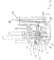
- a connector is identified in its entirety with the reference number 1.
- a first alternative embodiment of a connector 1 is shown in FIG Figure 1 shown.
- the plug connector 1 comprises seven plug contacts 10, 10 ', two of the plug contacts 10' serving as plug contacts for an electrical energy source or an electrical energy store.
- the further plug contacts 10 are designed as contacts for signal conducting means.
- the plug wall 11 has an outer surface 12 and an inner surface 13.
- a sealing element 14 is arranged on the outer surface 12 and is formed from a groove running around the outer surface 12 with a seal arranged therein. The seal protrudes from the outer surface 12 of the plug wall 11.
- the outer surface 12 has a locking element 15 which is designed as a pin.
- the outer surface 12 is formed parallel to the insertion direction, the sealing element 14 being arranged in front of the locking element 15 in the insertion direction. The sealing element 14 is thus inserted into a suitable socket in front of the locking element 15, so that a seal takes place before the locking.
- connection component 2 which is designated in its entirety by the reference number 2.
- the connection component 2 has a plug socket 20 that matches the plug connector 1.
- a base 23 of the socket 20 electrical contacts 18, 18 'are arranged.
- the electrical contacts 18 'are designed as counterparts to the plug contacts 10'.
- the electrical contacts 18 are designed as counterparts to the plug contacts 10. All electrical contacts 18, 18 'are arranged to match the plug contacts 10, 10'.
- the electrical contacts 18, 18 ′ in the base 23 are surrounded by a socket wall 21.
- the socket wall 21 includes an inner surface 22.
- the inner surface 22 of the socket wall 21 is arranged opposite that of an outer surface 24 of the base 23.
- the plug contacts 10, 10 ′ of this first alternative embodiment are not arranged symmetrically, so that the plug connection 1 can be inserted into the plug socket 20 in only one single orientation.
- the plug wall 11 When the plug connector 1 is inserted into the socket 20, the plug wall 11 is arranged in the space between the socket 23 and the socket wall 21.
- the inner surface 22 of the socket wall 21 forms a sealing closure with the sealing element 14 of the plug connector 1 protruding from the outer surface 12 of the plug wall 11.
- the socket wall 21 also has a latching device 25 which fits to the locking element 15 of the plug connector 1.
- the locking element 15 engages in the latching device 25 when the plug connector 1 is inserted into the socket 20.
- the latching connection between the locking element 15 and the latching device 25 must be overridden. In this way, an unintentional release of the locking connection due to vibrations is prevented.
- Figure 4b shows a connection system in which the plug connections 1 are inserted into the connection component 2, the locking elements 15 interacting with the latching devices 25.
- a wall of the housing 27 of the connection component 2 is shown as transparent, so that the sealing elements 14 of the plug connections 1 are visible.
- the sealing elements 14 are pressed against the inner surface 22 of the socket wall 21 so that they form a seal for the space in which the electrical contacts 18, 18 'and the plug contacts 10, 10' are arranged.
- the plug contacts 10, 10 'are connected with cables, as in FIG Figure 3 is pictured.
- the cables are led out of the connector 1 as a cable harness 4.
- the interior 17 is injected with a hotmelt material for sealing.
- the cable loom 4 extends through the hotmelt material. It is poured into the hotmelt material.
- the hotmelt material seals the interior 17 of the connector 1 from the outside. This means that no spray or rainwater can get to the power lines.
- the hotmelt material with which the interior 17 of the connector 1 is injected can be a thermoplastic urethane.
- the connection component 2 also has a housing 27 with an interior 6 in which the electrical contacts 18 are connected to a cable harness 5.
- the cable harness 5 is led out of the interior 6 in order to be connected to the circuit board of an electric motor 31.
- the interior 6 of the connection component 2 is injected with a hotmelt material.
- the cable loom 5 is thereby surrounded by the hotmelt material.
- the hotmelt material seals the interior 6 of the housing 27 from the outside so that no moisture can get into the connection component 2 along the cable 5.
- the hotmelt material with which the housing 27 is injected can be a potting polyamide.
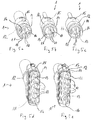
- Figures 5a-c and 5d-e each show a set of an alternative embodiment of the plug connector 1.
- the two sets of plug connectors 1 each have a matching arrangement of symmetrically arranged plug contacts 10. They differ in the alignment elements 16 which are arranged on the inner surface 13 of the plug wall 11. Means the alignment elements 16, the alignment of each connector 1 is determined. Despite the symmetrical arrangement of the plug contacts 10, it cannot be interchanged.
- the sockets 20 also have an in Figure 4a
- the illustrated second alternative embodiment of the connection component 2 has counter-structures 26 which match the alignment elements 16 and which are arranged on the base 23.
- the connectors 1 of a connector set cannot therefore be interchanged with one another. Each plug connector 1 is thus permanently assigned to a plug socket 20.
- connection component 2 can be arranged on a housing 32 of an electric motor 31.
- the connection component 2 has a sealing section 29 for connection to the housing 32.
- the sealing section 29 comprises two grooves 28 which are conical in the insertion direction.
- the connection component 2 can be arranged in a suitably configured recess on the housing 32 of the electric motor 31.
- the grooves 28 are arranged in one plane.
- the connection component 2 then forms the passage of the electrical line from the interior of the housing 32 to the outside.
- the grooves 28 seal the recess on the housing 32. Due to the conically tapering shape of the grooves 28, the edge of the recess can be pressed into the grooves 28 like a wedge and thus forms a sealing connection.
- the cable harness 5, which is led out of the connection component 2, has plugs 33 at its end, which can be connected to the circuit board of an electric motor 31.
- the electric motor is like in Figure 6 shown in the bottom bracket of a Electric bike 3 arranged. It supports the crankshaft 30 while driving, if additional energy is required for acceleration or on inclines. When no energy is required, it absorbs additional energy, which can be released, for example, by braking maneuvers.
- the electric motor 31 is connected to peripheral devices 34 via the connection component 2 and the plug connector 1 with the cable harnesses 4. They are supplied with energy by the electric motor 31 and can, for example, transmit data about the speed to the electric motor 31.
Landscapes
- Connector Housings Or Holding Contact Members (AREA)
Description
- Die Erfindung betrifft ein Anschluss-System für ein Elektrofahrrad mit einem Steckverbinder und mit einem Anschluss-Bauteil. Der Steckverbinder umfasst eine Mehrzahl von elektrischen Steckkontakten und eine Steckerwand, die die Steckkontakte in Umfangsrichtung umgibt.
- Fahrräder können unterstützende elektrische Motoren aufweisen, um den Fahrradfahrer z.B. bei Steigungen oder beim Beschleunigen zu entlasten. Die Motoren solcher Elektrofahrräder können am Tretlager angeordnet sein und Sensoren aufweisen, die das Drehmoment am Tretlager und die Geschwindigkeit des Fahrrads erfassen. Ein Schaltkreis auf einer Platine bestimmt aus einem Vergleich der Messdaten, ob der Motor das Elektrofahrrad beschleunigen muss, um dem Fahrer zu entlasten bzw. um eine vorbestimmte Geschwindigkeit zu halten. Bei Bremsmanövern können diese Motoren bei der Rekuperation als Generatoren mitwirken. Die umgewandelte Energie kann in externe elektrische Speicher eingespeist und zu einem späteren Zeitpunkt wieder abgerufen werden. Weiter können die Motoren als Energiequelle für Peripheriegeräte wie Beleuchtung, Geschwindigkeitsanzeige usw. dienen.
- Dazu benötigen die Motoren elektrische Leitungen zu den Energiespeichern und den Peripheriegeräten, um Energie oder Signale zu übermitteln. Da die Peripheriegeräte in der Regel nicht am Motor selbst sondern an einer anderen Stelle am Rahmen des Fahrrads angebracht sind, werden zur Verbindung Kabel benutzt, die über elektrische Steckverbinder mit entsprechenden Anschlüssen verbunden werden.
- Bekannt sind elektrische Anschlüsse, bei denen das Kabel durch das Motorgehäuse hindurchgeführt ist und bei denen direkt am Motorgehäuse keine Möglichkeit besteht, die elektrische Verbindung zu trennen. Eine elektrische Steckverbindung gibt es erst in einigem Abstand von dem Motorgehäuse. Häufig ist die elektrische Steckverbindung in der Mitte eines Kabels angeordnet, also als sogenannte fliegende Steckverbindung ausgebildet. Wünschenswert ist eine fest am Motorgehäuse angeordnete elektrische Steckverbindung. Allerdings ist im Bereich des Tretlagers nur wenig Platz. Außerdem ist die elektrische Steckverbindung dort Spritzwasser ausgesetzt.
-
US 2003/032321 A1 offenbart einen elektrischer Verbinder, umfassend ein inneres Gehäuse mit einem darin angeordneten Anschluss und ein elastomeres Außengehäuse das um das Innengehäuse herum angeordnet ist. Mindestens ein Dichtungselement erstreckt sich um eine Umfangsfläche des Außengehäuses. Ein Halteelement erstreckt sich von der Oberfläche nach außen erstreckt. InEP 1 211 755 A2 ist ein elektrischer Verbinder für ein Elektrofahrrad offenbart.EP 0 008 603 A1 offenbart eine aus Stecker und Dose bestehende Kupplung zum feuchtigkeitsdichten Verbinden von elektrischen Leitungen. Der genau in die Dose passende Stecker weist einen O-Ring auf und kann mit der Dose einrastend verriegelt werden. InUS 4,235,499 ist ein Steckverbindung offenbart, bei dem ein Kontakthalter hohlzylindrisch geformt ist und mindestens zwei Längsschlitze aufweist, die jeweils mit jeweils einer Schnappverriegelungsaussparung versehen sind. Eine Kontaktstütze, die in den Kontakthalter eingeführt werden kann, weist Vorsprünge auf, die in die Längsschlitze des ersten Kontaktträgers eingreifen und die in der endgültigen eingeführten Position der Steckverbindung in die zugehörigen Schnappverriegelungsaussparungen einrasten. InGB 1 329 561 - Aufgabe der Erfindung ist es, eine zuverlässige elektrische Steckverbindung zu schaffen, die zur Verwendung bei einem am Tretlager angeordneten Motor eines Elektrofahrrads geeignet ist. Ausgehend vom genannten Stand der Technik wird die Aufgabe gelöst durch die Merkmale der unabhängigen Ansprüche. Vorteilhafte Weiterbildungen sind Gegenstand der abhängigen Ansprüche.
- Der Steckverbinder umfasst eine Mehrzahl von elektrischen Steckkontakten und eine Steckerwand, die die Steckkontakte in Umfangsrichtung umgibt. Eine Außenfläche der Steckerwand ist mit einem umlaufenden Dichtelement versehen . Auf der Außenfläche der Steckerwand ist ein nach außen vorspringendes Verriegelungselement angeordnet.
- Die Erfindung beruht auf dem Gedanken, gleichzeitig beim Einstecken des Steckverbinders sowohl eine Abdichtung in Bezug auf die elektrischen Kontakte als auch eine Verriegelung des Steckverbinders zu erreichen. Dazu weist der Steckverbinder an der Außenfläche der Steckerwand ein umlaufendes Dichtelement auf. Das Dichtelement läuft um die Steckkontakte des Steckverbinders um, so dass die Steckkontakte durch das Dichtelement in einer passenden Buchse abgedichtet werden können.
- Weiter umfasst die Außenfläche der Steckerwand ein nach außen vorspringendes Verriegelungselement, das den Steckverbinder an der Steckerbuchse verriegelt. Damit ist der Steckverbinder gegen unbeabsichtigtes Lösen gesichert, so dass die elektrische Verbindung solange bestehen bleibt, bis der Steckverbinder von Hand entfernt wird.
- Die Außenfläche der Steckerwand ist vorzugsweise parallel zu der Einsteckrichtung des Steckverbinders ausgebildet. Damit kann die Steckerwand unkompliziert in eine passende Buchse eingeführt werden. Das Dichtelement springt mit Vorteil gegenüber der Außenfläche vor, so dass ein verbleibender Zwischenraum zwischen der Außenfläche und der Buchse überbrückt wird. Das Dichtelement kann als Dichtung ausgeführt sein, die in einer Nut der Seitenwand angeordnet ist.
- In Einsteckrichtung betrachtet ist das Dichtelement vor dem Verriegelungselement angeordnet. Indem die Elemente in Einsteckrichtung hintereinander gestaffelt sind, wird ausgenutzt, dass in dieser Richtung regelmäßig ausreichend Platz vorhanden ist. Im Gegenzug wird es möglich, den Steckverbinder in der zur Einsteckrichtung senkrechten Dimension kompakt zu halten.
- Das Verriegelungselement kann sich von der Außenfläche der Steckerwand in Richtung einer Stirnfläche erstrecken. Es ist möglich, die Stirnfläche so zu gestalten, dass sie mit einer Rastvorrichtung der zugehörigen Buchse zusammenwirkt. Allerdings steigt dann der Platzbedarf der elektrischen Steckverbindung in der zur Einsteckrichtung senkrechten Dimension. Von Vorteil ist es deswegen, wenn eine Seitenfläche des Verriegelungselements dazu ausgelegt ist, mit einer Rastvorrichtung zusammenzuwirken. Die Seitenfläche ist seitlich angeordnet bezogen auf die Richtung, die sich von der Außenfläche der Steckerwand zur Stirnfläche erstreckt. Insbesondere kann die Seitenfläche einen geneigten Abschnitt umfassen, der dazu ausgelegt ist, eine Rastvorrichtung beim Einführen des Steckverbinders zu spreizen.
- Das Verriegelungselement ist als Zapfen ausgebildet, dessen Achse senkrecht zur Außenfläche der Steckerwand ausgerichtet ist. Die Umfangsfläche des Zapfens bildet die Seitenfläche des Verriegelungselements. Der in Einsteckrichtung weisende Teil der Umfangsfläche ist dazu ausgelegt, eine Rastvorrichtung zu spreizen. Die Länge des Zapfens ist vorzugsweise so bemessen, dass die Stirnfläche nicht gegenüber der Rastvorrichtung vorspringt.
- Die Steckkontakte eines solchen Steckverbinders sind häufig symmetrisch angeordnet. Unter symmetrisch wird verstanden, dass die Steckkontakte durch eine Rotation um eine entlang der Einsteckrichtung verlaufenden Achse auf einander abgebildet werden können. Um eine Vertauschung der Pole auszuschließen, kann der erfindungsgemäße Steckverbinder mit einem Ausrichtelement versehen sein, so dass die elektrische Verbindung in nur genau einer Ausrichtung des Steckers hergestellt werden kann. Das Ausrichtelement ist vorzugsweise auf einer Innenfläche der Steckerwand angeordnet. Der Steckverbinder kann damit sicher und einfach in der richtigen Ausrichtung in eine passende Buchse einführt werden. Beschädigugnen an elektrischen Geräten, bei denen die Polung der Steckkontakte wichtig ist, werden damit vermieden.
- Mit Vorteil ist ein Innenraum des Steckverbinders mit einem Hotmelt-Material ausgespritzt, wobei sich ein Kabelstrang durch das Hotmelt-Material hindurch erstreckt. Unter einem Hotmelt-Material wird ein Kunststoffmaterial verstanden, das in einem flüssigen, erhitzten Zustand Oberflächen benetzt und sich nach dem Abkühlen dauerhaft verfestigt. Geeignet als solches Hotmelt-Material ist beispielsweise thermoplastisches Polyurethane (TPU). Das Hotmelt-Material dichtet den Raum zwischen dem Kabelstrang und der Innenwand des Steckverbinders ab. Weiter stabilisiert es den Kabelstrang in dem Steckverbinder. Der Kabelstrang kann sich nach Verlassen des Hotmelt-Materials bis zu dem Peripheriegerät erstrecken.
- Das erfindungsgemäße Anschluss-System umfasst einen Steckverbinder und ein Anschluss-Bauteil des Elektrofahrrads. Das Anschluss-Bauteil hat eine zu dem Steckverbinder passende Steckerbuchse. Die Steckerbuchse weist eine die elektrischen Kontakte in Umfangsrichtung umgebende Buchsenwand auf. Eine Innenfläche der Buchsenwand ist dazu ausgelegt, einen dichtenden Abschluss mit dem Dichtelement des Steckverbinders zu bilden.
- Mit dem Anschluss-Bauteil des Anschluss-Systems wird eine passende Steckerbuchse für den Steckverbinder bereitgestellt. Beim Einstecken des Steckverbinders wird die Außenfläche der Steckerwand in die Steckerbuchse eingeführt, so dass ein umlaufender Teil der Innenfläche der Buchsenwand um einen umlaufenden Teil der Außenfläche der Steckerwand angeordnet wird. Die Innenfläche der Buchsenwand der Steckerbuchse wird bei Einführung des Steckverbinders in Kontakt mit dem Dichtelement gebracht. Das Dichtelement wird beim Einsteckvorgang zwischen der Außenfläche der Steckerwand und der Innenfläche der Buchsenwand angeordnet. Vorzugsweise ist eine Presspassung derart vorgesehen, dass das Dichtelement senkrecht zur Einsteckrichtung komprimiert wird. Dadurch schließt das Dichtelement den Raum, in dem sich die elektrischen Kontakte und Steckkontakte befinden, von der äußeren Umgebung wasserdicht ab. Wasser, das an den Steckverbinder gelangt, kann damit nicht zwischen der Innenfläche der Buchsenwand und der Außenfläche der Steckerwand zu den elektrischen Kontakten fließen.
- Zweckmäßigerweise weist die Buchsenwand eine Rastvorrichtung auf, in die das Verriegelungselement des Steckverbinders einrastet, wenn der Steckverbinder in Eingriff mit der Buchse steht. Dies ermöglicht die sichere Verriegelung des Steckverbinders an der Steckerbuchse. Die Rastvorrichtung ist vorzugsweise so gestaltet, dass der an die Stirnfläche des Verriegelungselement angrenzende Raum frei bleibt. Dadurch wird es möglich, eine Mehrzahl von Steckerbuchsen auf kleinem Raum nebeneinander anzuordnen.
- Die Buchse weist mit Vorteil einen die elektrischen Kontakte umgebenden Sockel auf, wobei eine Außenfläche des Sockels der Innenfläche der Buchsenwand gegenüberliegt. Die Steckerwand wird teilweise oder vollständig in den Zwischenraum zwischen Sockel und Buchsenwand eingeführt. Damit wird der Weg zu den elektrischen Kontakten und den Steckkontakten für an dem Steckverbinder entlang fließendes Wasser verlängert und der Schutz vor eindringender Feuchtigkeit wird weiter erhöht.
- Weiter ist vorteilhafterweise in der Außenfläche des Sockels eine zu dem Ausrichtelement des Steckverbinders passende Gegenstruktur ausgebildet. Damit kann der Steckverbinder nur in einer festgelegten Ausrichtung in die Steckerbuchse eingeführt werden. Die Steckkontakte des Steckverbinders werden nur mit den vorgesehenen elektrischen Kontakten der Steckerbuchse verbunden.
- Es ist weiter zweckmäßig, dass das Anschluss-Bauteil ein Gehäuse aufweist, wobei ein Innenraum des Gehäuses mit einem Hotmelt-Material ausgespritzt ist und wobei ein Kabelstrang sich durch das Hotmelt-Material hindurch erstreckt. Mit dem Eingießen des Kabelstrangs in das Hotmelt-Material wird der Übergang zwischen dem Kabelstrang und dem Gehäuse abgedichtet. Weiter werden der Innenraum des Gehäuses sowie die Verbindungen der Kabelstränge zu den elektrischen Kontakten stabiliesiert.
- Mit Vorteil weist das Anschluss-Bauteil einen von dem Hotmelt-Material gebildeten Dichtabschnitt auf, der dazu ausgelegt ist, eine wasserdichte Verbindung zu dem Motorgehäuse des Elektrofahrrads herzustellen. Der Kabelstrang kann sich durch den Dichtabschnitt hindurch erstrecken. Es wird dazu vorzugsweise ein Hotmelt-Material verwendet, das eine hohe Flexibilität und gute Anschmiegbarkeit aufweist. In Betracht kommt beispielsweise ein Verguss-Polyamid Material. Das Anschluss-Bauteil kann mithilfe des Dichtabschnitts als abdichtende elektrische Durchführung an einem Gehäuse für einen Elektromotor fungieren. Der Dichtabschnitt kann eine Öffnung eines Raums abdichten, in dem elektrische Vorrichtungen wie z.B. Platinen angeordnet sind.
- Der Dichtabschnitt weist vorteilhafterweise zwei als Dichtflächen bestimmte Nuten auf. Die Nuten sind zweckmäßigerweise in einer Ebene angeordnet, durch die eine Einführrichtung definiert wird. Einführrichtung bezeichnet die Richtung, in der das Anschluss-Bauteil in eine zugehörige Ausnehmung des Motorgehäuses eingesetzt wird. Die Einführrichtung ist vorzugsweise parallel zu der Einsteckrichtung des elektrischen Steckverbinders. Die Nuten haben vorzugsweise eine parallel zu der Einführrichtung konisch zulaufende Form. Mittels der konisch zulaufenden Form wirkt der Rand der Ausnehnung wie ein Keil, der in die Nuten gedrückt wird. Dadurch wird eine sichere Abdichtung des Gehäuseinneren bewirkt.
- Weiter betrifft die Erfindung ein Elektrofahrrad mit einem solchen Anschluss-System, wobei erfindungsgemäß vorgesehen ist, dass das Elektrofahrrad einen auf die Tretkurbelwelle wirkenden Elektromotor aufweist, wobei der Elektromotor mit einem Elektromotorgehäuse umgeben ist und wobei der Dichtabschnitt des Anschluss-Bauteils mit dem Elektromotorgehäuse abdichtet.
- Die Erfindung betrifft ferner dass das Anschluss-System ein Satz von Steckverbinder aufweist, wobei wenigstens zwei der Steckverbinder eine übereinstimmende Anordnung von elektrischen Steckkontakten aufweisen und dass die Steckverbinder voneinander abweichende Ausrichtelemente aufweisen, und wobei der Anschluss-Bauteil Steckerbuchsen aufweist, die zu den Ausrichtelementen passende Gegenstrukturen aufweisen, die Steckverbinder des Steckverbinder-Satzes können damit nicht untereinander vertauscht werden. Der Satz kann drei Steckerverbinder mit jeweils zwei elektrischen Kontakten und zwei Steckverbinder mit jeweils fünf elektrischen Kontakten umfassen.
- Damit kann jeder Steckverbinder nur in Steckerbuchsen eingeführt werden, die eine passende Gegenstruktur an der Außenfläche des Sockels aufweisen. Dies vereinfacht und beschleunigt die Montage der Steckverbinder, da eine Zuordnung der Steckverbinder zu einem Peripheriegerät nicht zu erfolgen braucht.
- Die Erfindung wird anhand der beigefügten Zeichnungen, die bevorzugte Ausführungsbeispiele darstellen, näher erläutert. Es zeigen:
- Fig. 1:
- eine schematische Darstellung eines Steckverbinders in einer ersten Ausführungsform;
- Fig. 2:
- eine schematische Darstellung eines Anschluss-Bauteils in einer ersten Ausführungsform;
- Fig. 3:
- eine schematische Darstellung eines Steckverbinders mit transparenter Wandfläche;
- Fig. 4a, b:
- eine schematische Darstellung eines Anschluss-Bauteils in einer zweiten Ausführungsform ohne (a) und mit (b) angeschlossenen Steckverbindern;
- Fig. 5a-e:
- eine schematische Darstellung von Steckverbinder-Sätzen in einer zweiten Ausführungsform;
- Fig. 6:
- eine schematische Darstellung eines Elektrofahrads; und
- Fig. 7:
- eine schematische Darstellung eines Elektromotor-Gehäuses mit einem Anschluss-Bauteil.
- Ein Steckverbinder wird in seiner Gesamtheit mit den Bezugszeichen 1 gekennzeichnet. Ein erstes alternatives Ausführungsbeispiel eines Steckverbinders 1 wird in
Figur 1 dargestellt. - Der Steckverbinder 1 umfasst sieben Steckkontakte 10, 10', wobei zwei der Steckkontakte 10' als Steckkontakte für eine elektrische Energiequelle bzw. einen elektrischen Energiespeicher dienen. Die weiteren Steckkontakte 10 sind als Kontakte für Signalleitmittel ausgebildet. Die Steckkontakte 10 und 10' sind unterschiedlich ausgeformt. Die elektrischen Kontakte 10, 10' sind von einer Steckerwand 11 umgeben, die um die Steckkontakte 10, 10' umläuft. Die Steckerwand 11 weist eine Außenfläche 12 und eine Innenfläche 13 auf. An der Außenfläche 12 ist ein Dichtelement 14 angeordnet, das aus einer an der Außenfläche 12 umlaufenden Nut mit einer darin angeordneten Dichtung ausgebildet ist. Die Dichtung springt aus der Außenfläche 12 der Steckerwand 11 hervor.
- Weiter weist die Außenfläche 12 ein Verriegelungselement 15 auf, das als Zapfen ausgebildet ist. Die Außenfläche 12 ist parallel zur Einsteckrichtung ausgebildet, wobei das Dichtelement 14 in Einsteckrichtung vor dem Verriegelungselement 15 angeordnet ist. Damit wird das Dichtelement 14 vor dem Verriegelungselement 15 in eine passende Buchse eingeführt, so dass eine Abdichtung vor der Verriegelung erfolgt.
- In
Figur 2 wird ein Anschluss-Bauteil dargestellt, das in seiner Gesamtheit mit dem Bezugszeichen 2 bezeichnet wird. Das Anschluss-Bauteil 2 weist eine zum Steckverbinder 1 passende Steckerbuchse 20 auf. In einem Sockel 23 der Steckerbuchse 20 sind elektrische Kontakte 18, 18' angeordnet. Die elektrische Kontakte 18' sind als Gegenstücke zu den Stecckontakten 10' ausgebildet. Weiter sind die elektrischen Kontakte 18 als Gegenstücke zu den Steckkontakten 10 augebildet. Alle elektrischen Kontakte 18, 18' sind passend zu den Stecckontakten 10, 10' angeordnet. Die elektrischen Kontakte 18, 18' im Sockel 23 sind von einer Buchsenwand 21 umgeben. Die Buchsenwand 21 umfasst eine Innenfläche 22. Die Innenfläche 22 der Buchsenwand 21 ist der einer Außenfläche 24 des Sockels 23 gegenüber angeordnet. - Die Steckkontakte 10, 10' dieser ersten alternativen Ausführungsform sind nicht symmetrisch angeordnet, so dass die Steckverbindung 1 in nur einer einzigen Ausrichtung in die Steckerbuchse 20 eingeführt werden kann.
- Wenn der Steckverbinder 1 in die Steckerbuchse 20 eingeführt ist, ist die Steckerwand 11 in dem Zwischenraum zwischen dem Sockel 23 und der Buchsenwand 21 angeordnet. Dabei bildet die Innenfläche 22 der Buchsenwand 21 einen dichtenden Abschluss mit dem aus der Außenfläche 12 der Steckerwand 11 hervorspringenden Dichtelement 14 des Steckverbinders 1.
- Die Buchsenwand 21 weist weiter eine Rastvorrichtung 25 auf, die zu dem Verriegelungselement 15 des Steckverbinders 1 passt. Das Verriegelungselement 15 rastet in die Rastvorrichtung 25 ein, wenn der Steckverbinder 1 in die Steckerbuchse 20 eingeführt ist. Um den Steckverbinder 1 von der Steckerbuchse 20 zu lösen, muss die Rastverbindung zwischen dem Verriegelungselement 15 und der Rastvorrichtung 25 überdrückt werden. Damit wird eine unabsichtliche Lösung der Rastverbindung durch Erschütterungen verhindert.
Figur 4b stellt ein Anschluss-System dar, bei dem die Steckverbindungen 1 in das Anschluss-Bauteil 2 eingeführt sind, wobei die Verriegelungselemente 15 mit den Rastvorrichtungen 25 zusammenwirken. Weiter ist in derFigur 4b eine Wand des Gehäuses 27 des Anschluss-Bauteils 2 transparent dargestellt, so dass die Dichtelemente 14 der Steckverbindungen 1 sichtbar sind. Die Dichtelemente 14 sind an die Innenfläche 22 der Buchsenwand 21 gedrückt, so dass sie eine Abdichtung des Raums bilden, in den die elektrischen Kontakte 18, 18' sowie die Steckkontakte 10, 10' angeordnet sind. - Im Innenraum 17 des Steckverbinders 1 sind die Steckkontakte 10, 10' mit Kabeln verbunden, wie in
Figur 3 dargestellt wird. Die Kabel werden als Kabelstrang 4 aus dem Steckverbinder 1 herausgeführt. Der Innenraum 17 ist zur Abdichtung mit einem Hotmelt-Material ausgespritzt. Der Kabelstrang 4 erstreckt sich dabei durch das Hotmelt-Material hindurch. Er ist in das Hotmelt-Material eingegossen. Das Hotmelt-Material dichtet den Innenraum 17 des Steckverbinders 1 nach außen hin ab. Damit kann kein Spritz- oder Regenwasser an die stromführenden Leitungen gelangen. Das Hotmelt-Material, mit dem der Innenraum 17 des Steckverbinders 1 ausgespritzt ist, kann ein thermoplastisches Urethan sein. - Das Anschluss-Bauteil 2 weist weiter ein Gehäuse 27 mit einem Innenraum 6 auf, in dem die elektrischen Kontakte 18 mit einem Kabelstrang 5 verbunden sind. Der Kabelstrang 5 wird aus dem Innenraum 6 hinausgeführt, um mit der Platine eines Elektromotors 31 verbunden zu werden. Der Innenraum 6 des Anschluss-Bauteils 2 ist mit einem Hotmelt-Material ausgespritzt. Der Kabelstrang 5 ist dadurch von dem Hotmelt-Material umgeben. Das Hotmelt-Material dichtet den Innenraum 6 des Gehäuses 27 nach außen ab, so dass entlang der Kabel 5 keine Feuchtigkeit in das Anschluss-Bauteil 2 gelangen kann. Das Hotmelt-Material, mit dem das Gehäuse 27 ausgespritzt wird, kann ein Verguss-Polyamid sein.
-
Figuren 5a-c und 5d-e zeigen je einen Satz einer alternativen Ausführungsform des Steckverbinders 1. Die beiden Sätze der Steckverbinder 1 weisen jeweils eine übereinstimmende Anordnung von symmetrisch angeordneten Steckkontakten 10 auf. Sie unterscheiden sich in den Ausrichtelementen 16, die an der Innenfläche 13 der Steckerwand 11 angeordnet sind. Mittels der Ausrichtelementen 16 ist die Ausrichtung jeder Steckverbindung 1 festgelegt. Sie kann trotz der symmetrischen Anordnung der Steckkontakte 10 nicht vertauscht werden. - Weiter weisen die Steckerbuchsen 20 einer in
Figur 4a dargestellten zweiten alternativen Ausführungsform des Anschluss-Bauteils 2 zu den Ausrichtelementen 16 passende Gegenstrukturen 26 auf, die an den Sockel 23 angeordnet sind. Die Steckverbinder 1 eines Steckverbinder-Satzes können damit nicht untereinander vertauscht werden. Damit ist jeder Steckverbinder 1 einer Steckerbuchse 20 fest zugeordnet. - In
Figur 7 ist dargestellt, wie ein Anschluss-Bauteil 2 an ein Gehäuse 32 eines Elektromotors 31 angeordnet sein kann. Das Anschluss-Bauteil 2 weist zum Anschluss an das Gehäuse 32 einen Dichtabschnitt 29 auf. Der Dichtabschnitt 29 umfasst zwei Nuten 28, die in Einführrichtung konisch ausgebildet sind. Mittels des Dichtabschnitts 29 kann das Anschluss-Bauteil 2 in eine passend ausgestaltete Ausnehmung am Gehäuse 32 des Elektromotors 31 angeordnet werden. Um einfach in die Ausnehmung am Gehäuse 32 eingeführt zu werden, sind die Nuten 28 in einer Ebene angeordnet. Das Anschluss-Bauteil 2 bildet dann die Durchführung der elektrischen Leitung von dem Inneren des Gehäuses 32 nach außen. Die Nuten 28 dichten dabei Ausnehmung am Gehäuse 32 ab. Durch die konisch zulaufende Form der Nuten 28 kann der Rand der Ausnehmung wie ein Keil in die Nuten 28 hineingedrückt werden und bildet damit eine abdichtende Verbindung. - Der Kabelstrang 5, der aus dem Anschluss-Bauteil 2 herausgeführt wird, weist an seinem Ende Stecker 33 auf, die mit der Platine eines Elektromotors 31 verbunden werden können. Der Elektromotor ist wie in
Figur 6 dargestellt im Tretlager eines Elektrofahrrads 3 angeordnet. Er unterstützt die Tretkurbelwelle 30 während der Fahrt, wenn zusätzliche Energie zur Beschleunigung oder bei Steigungen benötigt wird. Wenn keine Energie benötigt wird, nimmt er zusätzliche Energie auf, die zum Beispiel durch Bremsmanöver frei werden kannn. Über das Anschluss-Bauteil 2 und die Steckverbinder 1 mit den Kabelsträngen 4 ist der Elektromotor 31 mit Peripheriegeräten 34 verbunden. Sie werden durch den Elektromotor 31 mit Energie versorgt und können zum Beispiel Daten über die Geschwindigkeit an den Elektromotor 31 übermitteln.
Claims (12)
- Anschluss-System für ein Elektrofahrrad (3), mit einem Steckverbinder (1) und mit einem Anschluss-Bauteil (2);a. der Steckverbinder umfassend eine Mehrzahl von elektrischen Steckkontakten (10, 10') und eine Steckerwand (11), die die Steckkontakte (10, 10') in Umfangsrichtung umgibt, und ein von der Außenfläche (12) der Steckerwand (11) nach außen vorspringendes Verriegelungselement (15) in Form eines Zapfens, dessen Achse senkrecht zur Außenfläche der Steckerwand ausgerichtet ist und dessen Umfangsfläche dazu ausgelegt ist, mit einer Rastvorrichtung (25) einer passenden Buchse zusammenzuwirken und die Rastvorrichtung beim Einführen des Steckverbinders in die Buchse zu spreizen,
dadurch gekennzeichnet, dass
die Außenfläche (12) der Steckerwand (11) mit einem umlaufenden Dichtelement (14) versehen ist, das in Einsteckrichtung betrachtet vor dem Verriegelungselement (15) angeordnet ist; und dassb. das Anschluss-Bauteil (2) eine zu dem Steckverbinder (1) passende Steckerbuchse (20) umfasst, wobei die Steckerbuchse (20) eine die elektrischen Kontakte (18, 18') in Umfangsrichtung umgebende Buchsenwand (21) aufweist und wobei eine Innenfläche (22) der Buchsenwand (21) dazu ausgelegt ist, einen dichtenden Abschluss mit dem Dichtelement (14) des Steckverbinders (1) zu bilden. - Anschluss-System nach Anspruch 1, dadurch gekennzeichnet, dass die Steckkontakte (10, 10') symmetrisch angeordnet sind und dass auf einer Innenfläche (13) der Steckerwand (11) ein Ausrichtelement (16) angeordnet ist.
- Anschluss-System nach Anspruch 1 oder 2, dadurch gekennzeichnet, dass ein Innenraum (17) des Steckverbinders (1) mit einem Hotmelt-Material ausgespritzt ist und dass ein Kabelstrang (4) sich durch das Hotmelt-Material hindurch erstreckt.
- Anschluss-System nach einem der Ansprüche 1 bis 3, dadurch gekennzeichnet, dass die Buchsenwand (21) eine Rastvorrichtung (25) aufweist, in die das Verriegelungselement (15) des Steckverbinders (1) einrastet, wenn der Steckverbinder (1) in Eingriff mit der Steckerbuchse (20) steht.
- Anschluss-System nach einem der Ansprüche 1 bis 4, dadurch gekennzeichnet, dass die Steckerbuchse (20) einen die elektrischen Kontakte (18, 18') umgebenden Sockel (23) aufweist, wobei eine Außenfläche (24) des Sockels (23) der Innenfläche (22) der Buchsenwand (21) gegenüberliegt.
- Anschluss-System nach Anspruch 5, dadurch gekennzeichnet, dass in der Außenfläche (24) des Sockels (23) eine zu dem Ausrichtelement (16) des Steckverbinders (1) passende Gegenstruktur (26) ausgebildet ist.
- Anschluss-System nach einem der Ansprüche 1 bis 6, dadurch gekennzeichnet, dass das Anschluss-Bauteil (2) ein Gehäuse (27) aufweist, dass ein Innenraum (33) des Gehäuses (27) mit einem Hotmelt-Material ausgespritzt ist und dass ein Kabelstrang (5) sich durch das Hotmelt-Material hindurch erstreckt.
- Anschluss-System nach Anspruch 7, dadurch gekennzeichnet, dass das Anschluss-Bauteil (2) einen von dem Hotmelt-Material gebildeten Dichtabschnitt (29) aufweist, der dazu ausgelegt ist, eine wasserdichte Verbindung zu dem Motorgehäuse des Elektrofahrrads herzustellen.
- Anschluss-System nach Anspruch 8, dadurch gekennzeichnet, dass das Hotmelt-Material in dem Dichtabschnitt (29) zwei als Dichtflächen bestimmte Nuten (28) aufweist.
- Anschluss-System nach Anspruch 9, dadurch gekennzeichnet, dass die Nuten (28) in einer Einführrichtung konisch zulaufen.
- Elektrofahrrad mit einem Anschluss-System (1, 2) nach einem der Ansprüche 1 bis 10, dadurch gekennzeichnet, dass das Elektrofahrrad (3) einen auf die Tretkurbelwelle (30) wirkenden Elektromotor (31) aufweist, wobei der Elektromotor (31) mit einem Elektromotorgehäuse (32) umgeben ist und wobei ein Dichtabschnitt des Anschluss-Bauteils (2) mit dem Elektromotorgehäuse (32) abdichtet.
- Anschluss-System nach einem der Ansprüche 1 bis 10, dadurch gekennzeichnet, dass das System einen Satz von Steckverbindern aufweist, wobei wenigstens zwei der Steckverbinder (1) eine übereinstimmende Anordnung von elektrischen Steckkontakten (10) aufweisen, wobei die Steckverbinder (1) voneinander abweichende Ausrichtelemente (16) aufweisen, und wobei das Anschluss-Bauteil (2) Steckerbuchsen aufweist, die zu den Ausrichtelementen (16) passende Gegenstrukturen (26) aufweisen, so dass die Steckverbinder (1) des Steckverbinder-Satzes nicht untereinander vertauscht werden können.
Priority Applications (4)
| Application Number | Priority Date | Filing Date | Title |
|---|---|---|---|
| PT141783860T PT2978077T (pt) | 2014-07-24 | 2014-07-24 | Conector de encaixe para uma bicicleta elétrica |
| EP14178386.0A EP2978077B1 (de) | 2014-07-24 | 2014-07-24 | Steckverbinder für ein Elektrofahrrad |
| ES14178386T ES2870723T3 (es) | 2014-07-24 | 2014-07-24 | Sistema de conexión para una bicicleta eléctrica |
| PL14178386T PL2978077T3 (pl) | 2014-07-24 | 2014-07-24 | Wtyczka dla roweru elektrycznego |
Applications Claiming Priority (1)
| Application Number | Priority Date | Filing Date | Title |
|---|---|---|---|
| EP14178386.0A EP2978077B1 (de) | 2014-07-24 | 2014-07-24 | Steckverbinder für ein Elektrofahrrad |
Publications (2)
| Publication Number | Publication Date |
|---|---|
| EP2978077A1 EP2978077A1 (de) | 2016-01-27 |
| EP2978077B1 true EP2978077B1 (de) | 2021-04-14 |
Family
ID=51224781
Family Applications (1)
| Application Number | Title | Priority Date | Filing Date |
|---|---|---|---|
| EP14178386.0A Active EP2978077B1 (de) | 2014-07-24 | 2014-07-24 | Steckverbinder für ein Elektrofahrrad |
Country Status (4)
| Country | Link |
|---|---|
| EP (1) | EP2978077B1 (de) |
| ES (1) | ES2870723T3 (de) |
| PL (1) | PL2978077T3 (de) |
| PT (1) | PT2978077T (de) |
Families Citing this family (6)
| Publication number | Priority date | Publication date | Assignee | Title |
|---|---|---|---|---|
| CN109028192A (zh) * | 2018-08-03 | 2018-12-18 | 广州迅速光电科技有限公司 | 一种节能的吸油烟机 |
| EP3648257A1 (de) | 2018-10-29 | 2020-05-06 | Werner Wirth GmbH | Steckverbinder, insbesondere für ein elektrofahrrad |
| EP3683893B1 (de) * | 2019-01-16 | 2022-06-08 | Werner Wirth GmbH | Elektrisches bauteil,verfahren zu seiner herstellung, und tragestruktur |
| DE102020202979A1 (de) | 2020-03-09 | 2021-09-09 | Magna Mirrors Holding Gmbh | Außenspiegelanordnung für Kraftfahrzeuge mit Beiklappantrieb, sowie Verfahren zur Montage und elektrischen Kontaktierung einer Außenspiegelanordnung mit Beiklappantrieb |
| EP4089851A1 (de) | 2021-05-12 | 2022-11-16 | Werner Wirth GmbH | Steckersystem für ein elektrofahrrad |
| DE102021116996A1 (de) * | 2021-07-01 | 2023-01-05 | Amphenol Tuchel Industrial GmbH | Steckverbinder mit Rahmen |
Citations (2)
| Publication number | Priority date | Publication date | Assignee | Title |
|---|---|---|---|---|
| GB1329561A (en) * | 1970-02-16 | 1973-09-12 | Bunker Ramo | Electrical two-part connectors |
| US4235499A (en) * | 1978-07-21 | 1980-11-25 | Maschinenfabrik Augsburg-Nurnberg, Aktiengesellschaft | Plug connection for contact supports |
Family Cites Families (7)
| Publication number | Priority date | Publication date | Assignee | Title |
|---|---|---|---|---|
| DE2835400C2 (de) * | 1978-08-12 | 1983-03-24 | kabelmetal electro GmbH, 3000 Hannover | Steckvorrichtung zum Durchverbinden von zwei elektrischen Leitungen mit mindestens zwei Adern |
| US6648686B2 (en) * | 2000-11-30 | 2003-11-18 | Shimano Inc. | Electrical connector |
| US20030032321A1 (en) * | 2001-08-13 | 2003-02-13 | Tyco Electronics Corporation | Sealed connector |
| ATE293218T1 (de) * | 2001-11-27 | 2005-04-15 | Freni Brembo Spa | Einrichtung zur befestigung eines elektrischen verbinders an den bremssattel einer scheibenbremse |
| TW200717950A (en) * | 2005-10-28 | 2007-05-01 | Shimano Kk | Bicycle wiring connector apparatus |
| DE202008006640U1 (de) * | 2008-05-09 | 2008-07-17 | Elkatec-Kabeltechnik Gmbh & Co. Kg | Vorrichtung zur Befestigung eines elektrischen Steckverbindungsteiles an einem Kastengehäuse |
| DE202013006110U1 (de) * | 2013-07-05 | 2013-08-14 | Hipo Systems Gmbh | Wasser- und staubdichte Stecker-Buchsen-Einheit mit verschiedenen Kontaktgruppen für die elektrische Mobilität wie z.B Pedelecs und E-Bike's |
-
2014
- 2014-07-24 ES ES14178386T patent/ES2870723T3/es active Active
- 2014-07-24 EP EP14178386.0A patent/EP2978077B1/de active Active
- 2014-07-24 PT PT141783860T patent/PT2978077T/pt unknown
- 2014-07-24 PL PL14178386T patent/PL2978077T3/pl unknown
Patent Citations (2)
| Publication number | Priority date | Publication date | Assignee | Title |
|---|---|---|---|---|
| GB1329561A (en) * | 1970-02-16 | 1973-09-12 | Bunker Ramo | Electrical two-part connectors |
| US4235499A (en) * | 1978-07-21 | 1980-11-25 | Maschinenfabrik Augsburg-Nurnberg, Aktiengesellschaft | Plug connection for contact supports |
Also Published As
| Publication number | Publication date |
|---|---|
| EP2978077A1 (de) | 2016-01-27 |
| PL2978077T3 (pl) | 2021-09-27 |
| PT2978077T (pt) | 2021-05-14 |
| ES2870723T3 (es) | 2021-10-27 |
Similar Documents
| Publication | Publication Date | Title |
|---|---|---|
| EP2978077B1 (de) | Steckverbinder für ein Elektrofahrrad | |
| DE102013213336B4 (de) | Elektrischer steckverbinder, ladedose und steckverbindersystem für ein elektro- oder hybridfahrzeug | |
| EP3122589B1 (de) | Als kupplung oder stecker ausgebildete steckvorrichtung | |
| DE102015204851A1 (de) | Mehradriges Kabel und Verfahren zur Herstellung eines mehradrigen Kabels | |
| DE102008059477A1 (de) | Elektrischer Mehrfachverteiler | |
| EP2879918B1 (de) | Kraftfahrzeugenergieleitung mit einem fremdstartstützpunkt | |
| WO2020007555A1 (de) | Steckverbindungselement für ein kraftfahrzeug und verfahren zum herstellen eines solchen steckverbindungselements | |
| DE202019005449U1 (de) | Antriebseinheit für ein Elektrofahrrad | |
| DE202017102886U1 (de) | Adapterstecker für ein Ladesystem zum Aufladen eines Elektrofahrzeugs | |
| EP1831965A1 (de) | Dichtungselement für flexible flat cable (ffc), fpc und andere flache leitungen mit und ohne rundleiter | |
| DE10139202B4 (de) | Elektrischer Verteiler | |
| DE202014011442U1 (de) | Anschluss-System für ein Elektrofahrrad | |
| DE102014019433A1 (de) | Elektronikbaueinheit für einen Elektromotor eines Einzelradantriebs eines Kraftfahrzeugs, Einzelradantrieb sowie Kraftfahrzeug | |
| DE3821861C1 (de) | ||
| DE3300519C2 (de) | ||
| EP0913889B1 (de) | Kupplungselement eines elektrischen Kabels | |
| DE102005041892A1 (de) | Elektrischer Verbinder | |
| DE102012207706B4 (de) | Lösbare elektrische Kontaktverbindung | |
| WO2017108803A1 (de) | Wasserdichtes konfektioniertes kabel mit steckverbinder | |
| DE102021204903A1 (de) | Herstellungsverfahren für einen Adapter | |
| BE1024426B1 (de) | Adapterstecker für ein Ladesystem zum Aufladen eines Elektrofahrzeugs | |
| EP3683893B1 (de) | Elektrisches bauteil,verfahren zu seiner herstellung, und tragestruktur | |
| DE202010015648U1 (de) | Kontakteinsatz für eine Anhängersteckdose | |
| DE102019126473B4 (de) | Baukastensystem für eine elektrische steckverbindung und verfahren zum herstellen einer elektrischen steckverbindung | |
| DE202017103404U1 (de) | Schutzkontakt-Steckverbinder aus montierten Einzelkomponenten |
Legal Events
| Date | Code | Title | Description |
|---|---|---|---|
| PUAI | Public reference made under article 153(3) epc to a published international application that has entered the european phase |
Free format text: ORIGINAL CODE: 0009012 |
|
| AK | Designated contracting states |
Kind code of ref document: A1 Designated state(s): AL AT BE BG CH CY CZ DE DK EE ES FI FR GB GR HR HU IE IS IT LI LT LU LV MC MK MT NL NO PL PT RO RS SE SI SK SM TR |
|
| AX | Request for extension of the european patent |
Extension state: BA ME |
|
| 17P | Request for examination filed |
Effective date: 20160518 |
|
| RBV | Designated contracting states (corrected) |
Designated state(s): AL AT BE BG CH CY CZ DE DK EE ES FI FR GB GR HR HU IE IS IT LI LT LU LV MC MK MT NL NO PL PT RO RS SE SI SK SM TR |
|
| STAA | Information on the status of an ep patent application or granted ep patent |
Free format text: STATUS: EXAMINATION IS IN PROGRESS |
|
| 17Q | First examination report despatched |
Effective date: 20170626 |
|
| GRAP | Despatch of communication of intention to grant a patent |
Free format text: ORIGINAL CODE: EPIDOSNIGR1 |
|
| STAA | Information on the status of an ep patent application or granted ep patent |
Free format text: STATUS: GRANT OF PATENT IS INTENDED |
|
| INTG | Intention to grant announced |
Effective date: 20200707 |
|
| GRAJ | Information related to disapproval of communication of intention to grant by the applicant or resumption of examination proceedings by the epo deleted |
Free format text: ORIGINAL CODE: EPIDOSDIGR1 |
|
| STAA | Information on the status of an ep patent application or granted ep patent |
Free format text: STATUS: EXAMINATION IS IN PROGRESS |
|
| GRAP | Despatch of communication of intention to grant a patent |
Free format text: ORIGINAL CODE: EPIDOSNIGR1 |
|
| STAA | Information on the status of an ep patent application or granted ep patent |
Free format text: STATUS: GRANT OF PATENT IS INTENDED |
|
| INTC | Intention to grant announced (deleted) | ||
| INTG | Intention to grant announced |
Effective date: 20201201 |
|
| GRAS | Grant fee paid |
Free format text: ORIGINAL CODE: EPIDOSNIGR3 |
|
| GRAA | (expected) grant |
Free format text: ORIGINAL CODE: 0009210 |
|
| STAA | Information on the status of an ep patent application or granted ep patent |
Free format text: STATUS: THE PATENT HAS BEEN GRANTED |
|
| AK | Designated contracting states |
Kind code of ref document: B1 Designated state(s): AL AT BE BG CH CY CZ DE DK EE ES FI FR GB GR HR HU IE IS IT LI LT LU LV MC MK MT NL NO PL PT RO RS SE SI SK SM TR |
|
| REG | Reference to a national code |
Ref country code: GB Ref legal event code: FG4D Free format text: NOT ENGLISH |
|
| REG | Reference to a national code |
Ref country code: CH Ref legal event code: EP |
|
| REG | Reference to a national code |
Ref country code: DE Ref legal event code: R096 Ref document number: 502014015478 Country of ref document: DE |
|
| REG | Reference to a national code |
Ref country code: IE Ref legal event code: FG4D Free format text: LANGUAGE OF EP DOCUMENT: GERMAN |
|
| REG | Reference to a national code |
Ref country code: PT Ref legal event code: SC4A Ref document number: 2978077 Country of ref document: PT Date of ref document: 20210514 Kind code of ref document: T Free format text: AVAILABILITY OF NATIONAL TRANSLATION Effective date: 20210507 Ref country code: CH Ref legal event code: NV Representative=s name: VALIPAT S.A. C/O BOVARD SA NEUCHATEL, CH |
|
| REG | Reference to a national code |
Ref country code: AT Ref legal event code: REF Ref document number: 1383294 Country of ref document: AT Kind code of ref document: T Effective date: 20210515 |
|
| REG | Reference to a national code |
Ref country code: NL Ref legal event code: FP |
|
| REG | Reference to a national code |
Ref country code: LT Ref legal event code: MG9D |
|
| REG | Reference to a national code |
Ref country code: ES Ref legal event code: FG2A Ref document number: 2870723 Country of ref document: ES Kind code of ref document: T3 Effective date: 20211027 |
|
| PG25 | Lapsed in a contracting state [announced via postgrant information from national office to epo] |
Ref country code: HR Free format text: LAPSE BECAUSE OF FAILURE TO SUBMIT A TRANSLATION OF THE DESCRIPTION OR TO PAY THE FEE WITHIN THE PRESCRIBED TIME-LIMIT Effective date: 20210414 Ref country code: FI Free format text: LAPSE BECAUSE OF FAILURE TO SUBMIT A TRANSLATION OF THE DESCRIPTION OR TO PAY THE FEE WITHIN THE PRESCRIBED TIME-LIMIT Effective date: 20210414 Ref country code: LT Free format text: LAPSE BECAUSE OF FAILURE TO SUBMIT A TRANSLATION OF THE DESCRIPTION OR TO PAY THE FEE WITHIN THE PRESCRIBED TIME-LIMIT Effective date: 20210414 Ref country code: BG Free format text: LAPSE BECAUSE OF FAILURE TO SUBMIT A TRANSLATION OF THE DESCRIPTION OR TO PAY THE FEE WITHIN THE PRESCRIBED TIME-LIMIT Effective date: 20210714 |
|
| PG25 | Lapsed in a contracting state [announced via postgrant information from national office to epo] |
Ref country code: GR Free format text: LAPSE BECAUSE OF FAILURE TO SUBMIT A TRANSLATION OF THE DESCRIPTION OR TO PAY THE FEE WITHIN THE PRESCRIBED TIME-LIMIT Effective date: 20210715 Ref country code: IS Free format text: LAPSE BECAUSE OF FAILURE TO SUBMIT A TRANSLATION OF THE DESCRIPTION OR TO PAY THE FEE WITHIN THE PRESCRIBED TIME-LIMIT Effective date: 20210814 Ref country code: LV Free format text: LAPSE BECAUSE OF FAILURE TO SUBMIT A TRANSLATION OF THE DESCRIPTION OR TO PAY THE FEE WITHIN THE PRESCRIBED TIME-LIMIT Effective date: 20210414 Ref country code: NO Free format text: LAPSE BECAUSE OF FAILURE TO SUBMIT A TRANSLATION OF THE DESCRIPTION OR TO PAY THE FEE WITHIN THE PRESCRIBED TIME-LIMIT Effective date: 20210714 Ref country code: SE Free format text: LAPSE BECAUSE OF FAILURE TO SUBMIT A TRANSLATION OF THE DESCRIPTION OR TO PAY THE FEE WITHIN THE PRESCRIBED TIME-LIMIT Effective date: 20210414 Ref country code: RS Free format text: LAPSE BECAUSE OF FAILURE TO SUBMIT A TRANSLATION OF THE DESCRIPTION OR TO PAY THE FEE WITHIN THE PRESCRIBED TIME-LIMIT Effective date: 20210414 |
|
| REG | Reference to a national code |
Ref country code: DE Ref legal event code: R097 Ref document number: 502014015478 Country of ref document: DE |
|
| PG25 | Lapsed in a contracting state [announced via postgrant information from national office to epo] |
Ref country code: SK Free format text: LAPSE BECAUSE OF FAILURE TO SUBMIT A TRANSLATION OF THE DESCRIPTION OR TO PAY THE FEE WITHIN THE PRESCRIBED TIME-LIMIT Effective date: 20210414 Ref country code: SM Free format text: LAPSE BECAUSE OF FAILURE TO SUBMIT A TRANSLATION OF THE DESCRIPTION OR TO PAY THE FEE WITHIN THE PRESCRIBED TIME-LIMIT Effective date: 20210414 Ref country code: CZ Free format text: LAPSE BECAUSE OF FAILURE TO SUBMIT A TRANSLATION OF THE DESCRIPTION OR TO PAY THE FEE WITHIN THE PRESCRIBED TIME-LIMIT Effective date: 20210414 Ref country code: EE Free format text: LAPSE BECAUSE OF FAILURE TO SUBMIT A TRANSLATION OF THE DESCRIPTION OR TO PAY THE FEE WITHIN THE PRESCRIBED TIME-LIMIT Effective date: 20210414 Ref country code: DK Free format text: LAPSE BECAUSE OF FAILURE TO SUBMIT A TRANSLATION OF THE DESCRIPTION OR TO PAY THE FEE WITHIN THE PRESCRIBED TIME-LIMIT Effective date: 20210414 Ref country code: RO Free format text: LAPSE BECAUSE OF FAILURE TO SUBMIT A TRANSLATION OF THE DESCRIPTION OR TO PAY THE FEE WITHIN THE PRESCRIBED TIME-LIMIT Effective date: 20210414 |
|
| PLBE | No opposition filed within time limit |
Free format text: ORIGINAL CODE: 0009261 |
|
| STAA | Information on the status of an ep patent application or granted ep patent |
Free format text: STATUS: NO OPPOSITION FILED WITHIN TIME LIMIT |
|
| 26N | No opposition filed |
Effective date: 20220117 |
|
| PG25 | Lapsed in a contracting state [announced via postgrant information from national office to epo] |
Ref country code: MC Free format text: LAPSE BECAUSE OF FAILURE TO SUBMIT A TRANSLATION OF THE DESCRIPTION OR TO PAY THE FEE WITHIN THE PRESCRIBED TIME-LIMIT Effective date: 20210414 |
|
| PG25 | Lapsed in a contracting state [announced via postgrant information from national office to epo] |
Ref country code: IS Free format text: LAPSE BECAUSE OF FAILURE TO SUBMIT A TRANSLATION OF THE DESCRIPTION OR TO PAY THE FEE WITHIN THE PRESCRIBED TIME-LIMIT Effective date: 20210814 Ref country code: LU Free format text: LAPSE BECAUSE OF NON-PAYMENT OF DUE FEES Effective date: 20210724 Ref country code: AL Free format text: LAPSE BECAUSE OF FAILURE TO SUBMIT A TRANSLATION OF THE DESCRIPTION OR TO PAY THE FEE WITHIN THE PRESCRIBED TIME-LIMIT Effective date: 20210414 |
|
| PG25 | Lapsed in a contracting state [announced via postgrant information from national office to epo] |
Ref country code: HU Free format text: LAPSE BECAUSE OF FAILURE TO SUBMIT A TRANSLATION OF THE DESCRIPTION OR TO PAY THE FEE WITHIN THE PRESCRIBED TIME-LIMIT; INVALID AB INITIO Effective date: 20140724 |
|
| PG25 | Lapsed in a contracting state [announced via postgrant information from national office to epo] |
Ref country code: CY Free format text: LAPSE BECAUSE OF FAILURE TO SUBMIT A TRANSLATION OF THE DESCRIPTION OR TO PAY THE FEE WITHIN THE PRESCRIBED TIME-LIMIT Effective date: 20210414 |
|
| PGFP | Annual fee paid to national office [announced via postgrant information from national office to epo] |
Ref country code: PT Payment date: 20230629 Year of fee payment: 10 |
|
| PGFP | Annual fee paid to national office [announced via postgrant information from national office to epo] |
Ref country code: NL Payment date: 20230720 Year of fee payment: 10 |
|
| PGFP | Annual fee paid to national office [announced via postgrant information from national office to epo] |
Ref country code: IT Payment date: 20230731 Year of fee payment: 10 Ref country code: IE Payment date: 20230726 Year of fee payment: 10 Ref country code: GB Payment date: 20230724 Year of fee payment: 10 Ref country code: ES Payment date: 20230821 Year of fee payment: 10 Ref country code: CH Payment date: 20230801 Year of fee payment: 10 Ref country code: AT Payment date: 20230718 Year of fee payment: 10 |
|
| PGFP | Annual fee paid to national office [announced via postgrant information from national office to epo] |
Ref country code: PL Payment date: 20230712 Year of fee payment: 10 Ref country code: FR Payment date: 20230720 Year of fee payment: 10 Ref country code: DE Payment date: 20230726 Year of fee payment: 10 Ref country code: BE Payment date: 20230719 Year of fee payment: 10 |
|
| PG25 | Lapsed in a contracting state [announced via postgrant information from national office to epo] |
Ref country code: MK Free format text: LAPSE BECAUSE OF FAILURE TO SUBMIT A TRANSLATION OF THE DESCRIPTION OR TO PAY THE FEE WITHIN THE PRESCRIBED TIME-LIMIT Effective date: 20210414 |