EP2976453B1 - Neue reinigungsvorrichtung und -verfahren - Google Patents
Neue reinigungsvorrichtung und -verfahren Download PDFInfo
- Publication number
- EP2976453B1 EP2976453B1 EP14712724.5A EP14712724A EP2976453B1 EP 2976453 B1 EP2976453 B1 EP 2976453B1 EP 14712724 A EP14712724 A EP 14712724A EP 2976453 B1 EP2976453 B1 EP 2976453B1
- Authority
- EP
- European Patent Office
- Prior art keywords
- rotatably mounted
- cleaning
- cylindrical cage
- mounted cylindrical
- solid particulate
- Prior art date
- Legal status (The legal status is an assumption and is not a legal conclusion. Google has not performed a legal analysis and makes no representation as to the accuracy of the status listed.)
- Active
Links
- 238000000034 method Methods 0.000 title claims description 105
- 238000004140 cleaning Methods 0.000 title claims description 86
- 239000007787 solid Substances 0.000 claims description 106
- 239000002245 particle Substances 0.000 claims description 87
- XLYOFNOQVPJJNP-UHFFFAOYSA-N water Substances O XLYOFNOQVPJJNP-UHFFFAOYSA-N 0.000 claims description 82
- 239000000758 substrate Substances 0.000 claims description 79
- 239000011236 particulate material Substances 0.000 claims description 77
- 238000003860 storage Methods 0.000 claims description 72
- 239000011538 cleaning material Substances 0.000 claims description 44
- 239000000203 mixture Substances 0.000 claims description 36
- 239000012459 cleaning agent Substances 0.000 claims description 24
- 238000001035 drying Methods 0.000 claims description 19
- 239000004753 textile Substances 0.000 claims description 18
- 238000011282 treatment Methods 0.000 claims description 18
- 239000012530 fluid Substances 0.000 claims description 16
- 238000009472 formulation Methods 0.000 claims description 13
- 230000000694 effects Effects 0.000 claims description 10
- 239000000835 fiber Substances 0.000 claims description 9
- 238000011068 loading method Methods 0.000 claims description 8
- 238000010438 heat treatment Methods 0.000 claims description 6
- 230000003134 recirculating effect Effects 0.000 claims description 4
- 239000011324 bead Substances 0.000 description 92
- 239000004744 fabric Substances 0.000 description 55
- 238000005406 washing Methods 0.000 description 38
- 239000003599 detergent Substances 0.000 description 28
- 230000008569 process Effects 0.000 description 28
- 230000009471 action Effects 0.000 description 23
- 230000008901 benefit Effects 0.000 description 19
- 239000000463 material Substances 0.000 description 18
- -1 optical brighteners Substances 0.000 description 13
- 238000000926 separation method Methods 0.000 description 12
- 230000002829 reductive effect Effects 0.000 description 9
- 239000000654 additive Substances 0.000 description 8
- 239000003795 chemical substances by application Substances 0.000 description 8
- 229920001577 copolymer Polymers 0.000 description 8
- 229920000728 polyester Polymers 0.000 description 8
- 239000004094 surface-active agent Substances 0.000 description 8
- 102000004190 Enzymes Human genes 0.000 description 7
- 108090000790 Enzymes Proteins 0.000 description 7
- 150000001875 compounds Chemical class 0.000 description 7
- 238000005265 energy consumption Methods 0.000 description 7
- 229940088598 enzyme Drugs 0.000 description 7
- 239000002689 soil Substances 0.000 description 7
- 239000004677 Nylon Substances 0.000 description 6
- 229920002302 Nylon 6,6 Polymers 0.000 description 6
- 239000004952 Polyamide Substances 0.000 description 6
- 239000007844 bleaching agent Substances 0.000 description 6
- 230000007613 environmental effect Effects 0.000 description 6
- 229920001778 nylon Polymers 0.000 description 6
- 229920002647 polyamide Polymers 0.000 description 6
- 229920000642 polymer Polymers 0.000 description 6
- 238000013461 design Methods 0.000 description 5
- 230000005484 gravity Effects 0.000 description 5
- 239000013618 particulate matter Substances 0.000 description 5
- 239000002304 perfume Substances 0.000 description 5
- 230000000717 retained effect Effects 0.000 description 5
- 239000007921 spray Substances 0.000 description 5
- QXNVGIXVLWOKEQ-UHFFFAOYSA-N Disodium Chemical class [Na][Na] QXNVGIXVLWOKEQ-UHFFFAOYSA-N 0.000 description 4
- XEEYBQQBJWHFJM-UHFFFAOYSA-N Iron Chemical compound [Fe] XEEYBQQBJWHFJM-UHFFFAOYSA-N 0.000 description 4
- 239000002253 acid Substances 0.000 description 4
- 239000011162 core material Substances 0.000 description 4
- 239000000975 dye Substances 0.000 description 4
- 230000003993 interaction Effects 0.000 description 4
- 229910052751 metal Inorganic materials 0.000 description 4
- 239000002184 metal Substances 0.000 description 4
- 238000005086 pumping Methods 0.000 description 4
- 239000000126 substance Substances 0.000 description 4
- 238000012546 transfer Methods 0.000 description 4
- 229920000742 Cotton Polymers 0.000 description 3
- 239000004743 Polypropylene Substances 0.000 description 3
- 239000012190 activator Substances 0.000 description 3
- 239000011248 coating agent Substances 0.000 description 3
- 238000000576 coating method Methods 0.000 description 3
- 239000012141 concentrate Substances 0.000 description 3
- 230000001419 dependent effect Effects 0.000 description 3
- 239000002270 dispersing agent Substances 0.000 description 3
- 230000002349 favourable effect Effects 0.000 description 3
- 230000002401 inhibitory effect Effects 0.000 description 3
- 230000003287 optical effect Effects 0.000 description 3
- 229920000139 polyethylene terephthalate Polymers 0.000 description 3
- 239000005020 polyethylene terephthalate Substances 0.000 description 3
- 229920000098 polyolefin Polymers 0.000 description 3
- 230000002265 prevention Effects 0.000 description 3
- 230000009467 reduction Effects 0.000 description 3
- 150000003839 salts Chemical class 0.000 description 3
- 238000012360 testing method Methods 0.000 description 3
- 239000001147 (3aR,5aS,9aS,9bR)-3a,6,6,9a-tetramethyl-2,4,5,5a,7,8,9,9b-octahydro-1H-benzo[e][1]benzofuran Substances 0.000 description 2
- CIOXZGOUEYHNBF-UHFFFAOYSA-N (carboxymethoxy)succinic acid Chemical compound OC(=O)COC(C(O)=O)CC(O)=O CIOXZGOUEYHNBF-UHFFFAOYSA-N 0.000 description 2
- QGZKDVFQNNGYKY-UHFFFAOYSA-O Ammonium Chemical compound [NH4+] QGZKDVFQNNGYKY-UHFFFAOYSA-O 0.000 description 2
- 108010065511 Amylases Proteins 0.000 description 2
- 102000013142 Amylases Human genes 0.000 description 2
- RYGMFSIKBFXOCR-UHFFFAOYSA-N Copper Chemical compound [Cu] RYGMFSIKBFXOCR-UHFFFAOYSA-N 0.000 description 2
- RTZKZFJDLAIYFH-UHFFFAOYSA-N Diethyl ether Chemical compound CCOCC RTZKZFJDLAIYFH-UHFFFAOYSA-N 0.000 description 2
- MHAJPDPJQMAIIY-UHFFFAOYSA-N Hydrogen peroxide Chemical compound OO MHAJPDPJQMAIIY-UHFFFAOYSA-N 0.000 description 2
- 108090001060 Lipase Proteins 0.000 description 2
- 102000004882 Lipase Human genes 0.000 description 2
- 239000004367 Lipase Substances 0.000 description 2
- PXHVJJICTQNCMI-UHFFFAOYSA-N Nickel Chemical compound [Ni] PXHVJJICTQNCMI-UHFFFAOYSA-N 0.000 description 2
- 108090000854 Oxidoreductases Proteins 0.000 description 2
- 102000004316 Oxidoreductases Human genes 0.000 description 2
- 108091005804 Peptidases Proteins 0.000 description 2
- KFSLWBXXFJQRDL-UHFFFAOYSA-N Peracetic acid Chemical compound CC(=O)OO KFSLWBXXFJQRDL-UHFFFAOYSA-N 0.000 description 2
- 239000004365 Protease Substances 0.000 description 2
- VYPSYNLAJGMNEJ-UHFFFAOYSA-N Silicium dioxide Chemical compound O=[Si]=O VYPSYNLAJGMNEJ-UHFFFAOYSA-N 0.000 description 2
- 229920002472 Starch Polymers 0.000 description 2
- MCMNRKCIXSYSNV-UHFFFAOYSA-N Zirconium dioxide Chemical compound O=[Zr]=O MCMNRKCIXSYSNV-UHFFFAOYSA-N 0.000 description 2
- 150000007513 acids Chemical class 0.000 description 2
- 238000013019 agitation Methods 0.000 description 2
- 229910052783 alkali metal Inorganic materials 0.000 description 2
- 150000001340 alkali metals Chemical class 0.000 description 2
- YPZUZOLGGMJZJO-LQKXBSAESA-N ambroxan Chemical compound CC([C@@H]1CC2)(C)CCC[C@]1(C)[C@@H]1[C@]2(C)OCC1 YPZUZOLGGMJZJO-LQKXBSAESA-N 0.000 description 2
- 235000019418 amylase Nutrition 0.000 description 2
- 238000013459 approach Methods 0.000 description 2
- QMKYBPDZANOJGF-UHFFFAOYSA-N benzene-1,3,5-tricarboxylic acid Chemical compound OC(=O)C1=CC(C(O)=O)=CC(C(O)=O)=C1 QMKYBPDZANOJGF-UHFFFAOYSA-N 0.000 description 2
- 239000002738 chelating agent Substances 0.000 description 2
- 229910052802 copper Inorganic materials 0.000 description 2
- 239000010949 copper Substances 0.000 description 2
- 108010005400 cutinase Proteins 0.000 description 2
- 238000011161 development Methods 0.000 description 2
- 238000009826 distribution Methods 0.000 description 2
- ONKNPOPIGWHAQC-UHFFFAOYSA-N galaxolide Chemical compound C1OCC(C)C2=C1C=C1C(C)(C)C(C)C(C)(C)C1=C2 ONKNPOPIGWHAQC-UHFFFAOYSA-N 0.000 description 2
- 239000011521 glass Substances 0.000 description 2
- 239000008233 hard water Substances 0.000 description 2
- 229910052742 iron Inorganic materials 0.000 description 2
- 235000019421 lipase Nutrition 0.000 description 2
- YDSWCNNOKPMOTP-UHFFFAOYSA-N mellitic acid Chemical compound OC(=O)C1=C(C(O)=O)C(C(O)=O)=C(C(O)=O)C(C(O)=O)=C1C(O)=O YDSWCNNOKPMOTP-UHFFFAOYSA-N 0.000 description 2
- 150000002739 metals Chemical class 0.000 description 2
- 238000002156 mixing Methods 0.000 description 2
- 238000004806 packaging method and process Methods 0.000 description 2
- 229920001707 polybutylene terephthalate Polymers 0.000 description 2
- 229920005646 polycarboxylate Polymers 0.000 description 2
- 229920001155 polypropylene Polymers 0.000 description 2
- 229920002635 polyurethane Polymers 0.000 description 2
- 239000004814 polyurethane Substances 0.000 description 2
- 238000011084 recovery Methods 0.000 description 2
- 239000008237 rinsing water Substances 0.000 description 2
- 239000012798 spherical particle Substances 0.000 description 2
- 238000005507 spraying Methods 0.000 description 2
- 239000003381 stabilizer Substances 0.000 description 2
- 235000019698 starch Nutrition 0.000 description 2
- 230000003068 static effect Effects 0.000 description 2
- 239000004575 stone Substances 0.000 description 2
- 230000032258 transport Effects 0.000 description 2
- 230000003442 weekly effect Effects 0.000 description 2
- 239000002023 wood Substances 0.000 description 2
- 150000000183 1,3-benzoxazoles Chemical class 0.000 description 1
- WURBVZBTWMNKQT-UHFFFAOYSA-N 1-(4-chlorophenoxy)-3,3-dimethyl-1-(1,2,4-triazol-1-yl)butan-2-one Chemical compound C1=NC=NN1C(C(=O)C(C)(C)C)OC1=CC=C(Cl)C=C1 WURBVZBTWMNKQT-UHFFFAOYSA-N 0.000 description 1
- OSSNTDFYBPYIEC-UHFFFAOYSA-N 1-ethenylimidazole Chemical compound C=CN1C=CN=C1 OSSNTDFYBPYIEC-UHFFFAOYSA-N 0.000 description 1
- VJSWLXWONORKLD-UHFFFAOYSA-N 2,4,6-trihydroxybenzene-1,3,5-trisulfonic acid Chemical compound OC1=C(S(O)(=O)=O)C(O)=C(S(O)(=O)=O)C(O)=C1S(O)(=O)=O VJSWLXWONORKLD-UHFFFAOYSA-N 0.000 description 1
- ZWCZPVMIHLKVLD-UHFFFAOYSA-N 2,5-diphenyl-3,4-dihydropyrazole Chemical class C1CC(C=2C=CC=CC=2)=NN1C1=CC=CC=C1 ZWCZPVMIHLKVLD-UHFFFAOYSA-N 0.000 description 1
- CFPOJWPDQWJEMO-UHFFFAOYSA-N 2-(1,2-dicarboxyethoxy)butanedioic acid Chemical compound OC(=O)CC(C(O)=O)OC(C(O)=O)CC(O)=O CFPOJWPDQWJEMO-UHFFFAOYSA-N 0.000 description 1
- UGFSLKRMHPGLFU-UHFFFAOYSA-N 2-[5-(1,3-benzoxazol-2-yl)thiophen-2-yl]-1,3-benzoxazole Chemical compound C1=CC=C2OC(C3=CC=C(S3)C=3OC4=CC=CC=C4N=3)=NC2=C1 UGFSLKRMHPGLFU-UHFFFAOYSA-N 0.000 description 1
- GLVYLTSKTCWWJR-UHFFFAOYSA-N 2-carbonoperoxoylbenzoic acid Chemical compound OOC(=O)C1=CC=CC=C1C(O)=O GLVYLTSKTCWWJR-UHFFFAOYSA-N 0.000 description 1
- CNGYZEMWVAWWOB-UHFFFAOYSA-N 4,4'-bis({4-anilino-6-[bis(2-hydroxyethyl)amino]-1,3,5-triazin-2-yl}amino)stilbene-2,2'-disulfonic acid Chemical compound N=1C(NC=2C=C(C(C=CC=3C(=CC(NC=4N=C(N=C(NC=5C=CC=CC=5)N=4)N(CCO)CCO)=CC=3)S(O)(=O)=O)=CC=2)S(O)(=O)=O)=NC(N(CCO)CCO)=NC=1NC1=CC=CC=C1 CNGYZEMWVAWWOB-UHFFFAOYSA-N 0.000 description 1
- ORMHZBNNECIKOH-UHFFFAOYSA-N 4-(4-hydroxy-4-methylpentyl)cyclohex-3-ene-1-carbaldehyde Chemical compound CC(C)(O)CCCC1=CCC(C=O)CC1 ORMHZBNNECIKOH-UHFFFAOYSA-N 0.000 description 1
- MPTSZKDKXHMKIE-UHFFFAOYSA-N 4-(4-hydroxy-4-methylpentyl)cyclohexene-1-carbaldehyde Chemical compound CC(C)(O)CCCC1CCC(C=O)=CC1 MPTSZKDKXHMKIE-UHFFFAOYSA-N 0.000 description 1
- HRHCYUBSBRXMIN-UHFFFAOYSA-N 5-[(4,6-dianilino-1,3,5-triazin-2-yl)amino]-2-[2-[4-[(4,6-dianilino-1,3,5-triazin-2-yl)amino]-2-sulfophenyl]ethenyl]benzenesulfonic acid Chemical compound C=1C=C(C=CC=2C(=CC(NC=3N=C(NC=4C=CC=CC=4)N=C(NC=4C=CC=CC=4)N=3)=CC=2)S(O)(=O)=O)C(S(=O)(=O)O)=CC=1NC(N=C(NC=1C=CC=CC=1)N=1)=NC=1NC1=CC=CC=C1 HRHCYUBSBRXMIN-UHFFFAOYSA-N 0.000 description 1
- YGUMVDWOQQJBGA-UHFFFAOYSA-N 5-[(4-anilino-6-morpholin-4-yl-1,3,5-triazin-2-yl)amino]-2-[2-[4-[(4-anilino-6-morpholin-4-yl-1,3,5-triazin-2-yl)amino]-2-sulfophenyl]ethenyl]benzenesulfonic acid Chemical compound C=1C=C(C=CC=2C(=CC(NC=3N=C(N=C(NC=4C=CC=CC=4)N=3)N3CCOCC3)=CC=2)S(O)(=O)=O)C(S(=O)(=O)O)=CC=1NC(N=C(N=1)N2CCOCC2)=NC=1NC1=CC=CC=C1 YGUMVDWOQQJBGA-UHFFFAOYSA-N 0.000 description 1
- VSNAWXHIKBJFHM-BUHFOSPRSA-N 5-[[4-anilino-6-(methylamino)-1,3,5-triazin-2-yl]amino]-2-[(e)-2-[4-[[4-anilino-6-(methylamino)-1,3,5-triazin-2-yl]amino]-2-sulfophenyl]ethenyl]benzenesulfonic acid Chemical compound N=1C(NC=2C=C(C(\C=C\C=3C(=CC(NC=4N=C(NC=5C=CC=CC=5)N=C(NC)N=4)=CC=3)S(O)(=O)=O)=CC=2)S(O)(=O)=O)=NC(NC)=NC=1NC1=CC=CC=C1 VSNAWXHIKBJFHM-BUHFOSPRSA-N 0.000 description 1
- WNUUEQSIAHJIGU-BUHFOSPRSA-N 5-[[4-anilino-6-[2-hydroxyethyl(methyl)amino]-1,3,5-triazin-2-yl]amino]-2-[(e)-2-[4-[[4-anilino-6-[2-hydroxyethyl(methyl)amino]-1,3,5-triazin-2-yl]amino]-2-sulfophenyl]ethenyl]benzenesulfonic acid Chemical compound N=1C(NC=2C=C(C(\C=C\C=3C(=CC(NC=4N=C(N=C(NC=5C=CC=CC=5)N=4)N(C)CCO)=CC=3)S(O)(=O)=O)=CC=2)S(O)(=O)=O)=NC(N(CCO)C)=NC=1NC1=CC=CC=C1 WNUUEQSIAHJIGU-BUHFOSPRSA-N 0.000 description 1
- LDCLYCYEPBDTIV-UHFFFAOYSA-N 6-[[4-[(6-hydroperoxy-6-oxohexyl)carbamoyl]benzoyl]amino]hexaneperoxoic acid Chemical compound OOC(=O)CCCCCNC(=O)C1=CC=C(C(=O)NCCCCCC(=O)OO)C=C1 LDCLYCYEPBDTIV-UHFFFAOYSA-N 0.000 description 1
- 239000004382 Amylase Substances 0.000 description 1
- OYPRJOBELJOOCE-UHFFFAOYSA-N Calcium Chemical compound [Ca] OYPRJOBELJOOCE-UHFFFAOYSA-N 0.000 description 1
- 229920002134 Carboxymethyl cellulose Polymers 0.000 description 1
- 108010059892 Cellulase Proteins 0.000 description 1
- 108010084185 Cellulases Proteins 0.000 description 1
- 102000005575 Cellulases Human genes 0.000 description 1
- 229920003043 Cellulose fiber Polymers 0.000 description 1
- ZAMOUSCENKQFHK-UHFFFAOYSA-N Chlorine atom Chemical compound [Cl] ZAMOUSCENKQFHK-UHFFFAOYSA-N 0.000 description 1
- 102000011413 Chondroitinases and Chondroitin Lyases Human genes 0.000 description 1
- 108010023736 Chondroitinases and Chondroitin Lyases Proteins 0.000 description 1
- VYZAMTAEIAYCRO-UHFFFAOYSA-N Chromium Chemical compound [Cr] VYZAMTAEIAYCRO-UHFFFAOYSA-N 0.000 description 1
- KCXVZYZYPLLWCC-UHFFFAOYSA-N EDTA Chemical compound OC(=O)CN(CC(O)=O)CCN(CC(O)=O)CC(O)=O KCXVZYZYPLLWCC-UHFFFAOYSA-N 0.000 description 1
- 101710121765 Endo-1,4-beta-xylanase Proteins 0.000 description 1
- 108090000371 Esterases Proteins 0.000 description 1
- VGGSQFUCUMXWEO-UHFFFAOYSA-N Ethene Chemical compound C=C VGGSQFUCUMXWEO-UHFFFAOYSA-N 0.000 description 1
- 239000005977 Ethylene Substances 0.000 description 1
- 108010003272 Hyaluronate lyase Proteins 0.000 description 1
- 102000001974 Hyaluronidases Human genes 0.000 description 1
- 229920006309 Invista Polymers 0.000 description 1
- 108010029541 Laccase Proteins 0.000 description 1
- 102000003820 Lipoxygenases Human genes 0.000 description 1
- 108090000128 Lipoxygenases Proteins 0.000 description 1
- JLVVSXFLKOJNIY-UHFFFAOYSA-N Magnesium ion Chemical compound [Mg+2] JLVVSXFLKOJNIY-UHFFFAOYSA-N 0.000 description 1
- PWHULOQIROXLJO-UHFFFAOYSA-N Manganese Chemical compound [Mn] PWHULOQIROXLJO-UHFFFAOYSA-N 0.000 description 1
- WHNWPMSKXPGLAX-UHFFFAOYSA-N N-Vinyl-2-pyrrolidone Chemical compound C=CN1CCCC1=O WHNWPMSKXPGLAX-UHFFFAOYSA-N 0.000 description 1
- 150000001204 N-oxides Chemical class 0.000 description 1
- 239000006057 Non-nutritive feed additive Substances 0.000 description 1
- 229920002292 Nylon 6 Polymers 0.000 description 1
- 102000035195 Peptidases Human genes 0.000 description 1
- 108700020962 Peroxidase Proteins 0.000 description 1
- 102000003992 Peroxidases Human genes 0.000 description 1
- 108010081873 Persil Proteins 0.000 description 1
- 108010064785 Phospholipases Proteins 0.000 description 1
- 102000015439 Phospholipases Human genes 0.000 description 1
- 239000004698 Polyethylene Substances 0.000 description 1
- 239000002202 Polyethylene glycol Substances 0.000 description 1
- 108010059820 Polygalacturonase Proteins 0.000 description 1
- 229920000388 Polyphosphate Polymers 0.000 description 1
- 108091007187 Reductases Proteins 0.000 description 1
- 102100037486 Reverse transcriptase/ribonuclease H Human genes 0.000 description 1
- 229910052581 Si3N4 Inorganic materials 0.000 description 1
- 229910000831 Steel Inorganic materials 0.000 description 1
- KDYFGRWQOYBRFD-UHFFFAOYSA-N Succinic acid Natural products OC(=O)CCC(O)=O KDYFGRWQOYBRFD-UHFFFAOYSA-N 0.000 description 1
- ATJFFYVFTNAWJD-UHFFFAOYSA-N Tin Chemical compound [Sn] ATJFFYVFTNAWJD-UHFFFAOYSA-N 0.000 description 1
- RTAQQCXQSZGOHL-UHFFFAOYSA-N Titanium Chemical compound [Ti] RTAQQCXQSZGOHL-UHFFFAOYSA-N 0.000 description 1
- 102000003425 Tyrosinase Human genes 0.000 description 1
- 108060008724 Tyrosinase Proteins 0.000 description 1
- HCHKCACWOHOZIP-UHFFFAOYSA-N Zinc Chemical compound [Zn] HCHKCACWOHOZIP-UHFFFAOYSA-N 0.000 description 1
- 230000001133 acceleration Effects 0.000 description 1
- 230000000996 additive effect Effects 0.000 description 1
- 230000002411 adverse Effects 0.000 description 1
- 150000001298 alcohols Chemical class 0.000 description 1
- 150000001299 aldehydes Chemical class 0.000 description 1
- 229910000288 alkali metal carbonate Inorganic materials 0.000 description 1
- 150000008041 alkali metal carbonates Chemical class 0.000 description 1
- 229910052910 alkali metal silicate Inorganic materials 0.000 description 1
- 229910052784 alkaline earth metal Inorganic materials 0.000 description 1
- 150000001342 alkaline earth metals Chemical class 0.000 description 1
- 239000000956 alloy Substances 0.000 description 1
- 229910045601 alloy Inorganic materials 0.000 description 1
- 108090000637 alpha-Amylases Proteins 0.000 description 1
- 108010084650 alpha-N-arabinofuranosidase Proteins 0.000 description 1
- 239000004411 aluminium Substances 0.000 description 1
- 229910052782 aluminium Inorganic materials 0.000 description 1
- XAGFODPZIPBFFR-UHFFFAOYSA-N aluminium Chemical compound [Al] XAGFODPZIPBFFR-UHFFFAOYSA-N 0.000 description 1
- PNEYBMLMFCGWSK-UHFFFAOYSA-N aluminium oxide Inorganic materials [O-2].[O-2].[O-2].[Al+3].[Al+3] PNEYBMLMFCGWSK-UHFFFAOYSA-N 0.000 description 1
- 229910000323 aluminium silicate Inorganic materials 0.000 description 1
- 150000003863 ammonium salts Chemical class 0.000 description 1
- 229940025131 amylases Drugs 0.000 description 1
- 125000000129 anionic group Chemical group 0.000 description 1
- 239000003945 anionic surfactant Substances 0.000 description 1
- 238000010936 aqueous wash Methods 0.000 description 1
- QVGXLLKOCUKJST-UHFFFAOYSA-N atomic oxygen Chemical compound [O] QVGXLLKOCUKJST-UHFFFAOYSA-N 0.000 description 1
- 230000009286 beneficial effect Effects 0.000 description 1
- 125000003785 benzimidazolyl group Chemical class N1=C(NC2=C1C=CC=C2)* 0.000 description 1
- ZYGHJZDHTFUPRJ-UHFFFAOYSA-N benzo-alpha-pyrone Natural products C1=CC=C2OC(=O)C=CC2=C1 ZYGHJZDHTFUPRJ-UHFFFAOYSA-N 0.000 description 1
- XJHABGPPCLHLLV-UHFFFAOYSA-N benzo[de]isoquinoline-1,3-dione Chemical class C1=CC(C(=O)NC2=O)=C3C2=CC=CC3=C1 XJHABGPPCLHLLV-UHFFFAOYSA-N 0.000 description 1
- KDYFGRWQOYBRFD-NUQCWPJISA-N butanedioic acid Chemical compound O[14C](=O)CC[14C](O)=O KDYFGRWQOYBRFD-NUQCWPJISA-N 0.000 description 1
- 239000011575 calcium Substances 0.000 description 1
- 229910001424 calcium ion Inorganic materials 0.000 description 1
- 125000004432 carbon atom Chemical group C* 0.000 description 1
- 239000001768 carboxy methyl cellulose Substances 0.000 description 1
- 235000010948 carboxy methyl cellulose Nutrition 0.000 description 1
- 150000001733 carboxylic acid esters Chemical class 0.000 description 1
- 239000008112 carboxymethyl-cellulose Substances 0.000 description 1
- 229940105329 carboxymethylcellulose Drugs 0.000 description 1
- 239000011111 cardboard Substances 0.000 description 1
- 239000000969 carrier Substances 0.000 description 1
- 230000003197 catalytic effect Effects 0.000 description 1
- 239000003093 cationic surfactant Substances 0.000 description 1
- 229940106157 cellulase Drugs 0.000 description 1
- 229920002301 cellulose acetate Polymers 0.000 description 1
- 239000000919 ceramic Substances 0.000 description 1
- 229910010293 ceramic material Inorganic materials 0.000 description 1
- 239000000460 chlorine Substances 0.000 description 1
- 229910052801 chlorine Inorganic materials 0.000 description 1
- 239000011651 chromium Substances 0.000 description 1
- 229910052804 chromium Inorganic materials 0.000 description 1
- 239000004927 clay Substances 0.000 description 1
- 239000010941 cobalt Substances 0.000 description 1
- 229910017052 cobalt Inorganic materials 0.000 description 1
- GUTLYIVDDKVIGB-UHFFFAOYSA-N cobalt atom Chemical compound [Co] GUTLYIVDDKVIGB-UHFFFAOYSA-N 0.000 description 1
- 238000010276 construction Methods 0.000 description 1
- 235000001671 coumarin Nutrition 0.000 description 1
- AFYCEAFSNDLKSX-UHFFFAOYSA-N coumarin 460 Chemical compound CC1=CC(=O)OC2=CC(N(CC)CC)=CC=C21 AFYCEAFSNDLKSX-UHFFFAOYSA-N 0.000 description 1
- 150000004775 coumarins Chemical class 0.000 description 1
- 230000007812 deficiency Effects 0.000 description 1
- 230000006866 deterioration Effects 0.000 description 1
- 230000001627 detrimental effect Effects 0.000 description 1
- VTIIJXUACCWYHX-UHFFFAOYSA-L disodium;carboxylatooxy carbonate Chemical compound [Na+].[Na+].[O-]C(=O)OOC([O-])=O VTIIJXUACCWYHX-UHFFFAOYSA-L 0.000 description 1
- JHUXOSATQXGREM-UHFFFAOYSA-N dodecanediperoxoic acid Chemical compound OOC(=O)CCCCCCCCCCC(=O)OO JHUXOSATQXGREM-UHFFFAOYSA-N 0.000 description 1
- 238000005008 domestic process Methods 0.000 description 1
- 238000010981 drying operation Methods 0.000 description 1
- 150000002148 esters Chemical class 0.000 description 1
- 150000002170 ethers Chemical class 0.000 description 1
- 108010093305 exopolygalacturonase Proteins 0.000 description 1
- 238000002474 experimental method Methods 0.000 description 1
- 239000002979 fabric softener Substances 0.000 description 1
- 238000011049 filling Methods 0.000 description 1
- 239000003205 fragrance Substances 0.000 description 1
- 108010002430 hemicellulase Proteins 0.000 description 1
- 229920001519 homopolymer Polymers 0.000 description 1
- 229960002773 hyaluronidase Drugs 0.000 description 1
- 230000002209 hydrophobic effect Effects 0.000 description 1
- 239000003752 hydrotrope Substances 0.000 description 1
- 238000010348 incorporation Methods 0.000 description 1
- 230000001788 irregular Effects 0.000 description 1
- 108010011519 keratan-sulfate endo-1,4-beta-galactosidase Proteins 0.000 description 1
- 150000002576 ketones Chemical class 0.000 description 1
- 239000011133 lead Substances 0.000 description 1
- 239000010985 leather Substances 0.000 description 1
- 108010062085 ligninase Proteins 0.000 description 1
- 230000000670 limiting effect Effects 0.000 description 1
- 239000012669 liquid formulation Substances 0.000 description 1
- 238000005461 lubrication Methods 0.000 description 1
- 239000011777 magnesium Substances 0.000 description 1
- 229910001425 magnesium ion Inorganic materials 0.000 description 1
- FPYJFEHAWHCUMM-UHFFFAOYSA-N maleic anhydride Chemical compound O=C1OC(=O)C=C1 FPYJFEHAWHCUMM-UHFFFAOYSA-N 0.000 description 1
- 229910052748 manganese Inorganic materials 0.000 description 1
- 239000011572 manganese Substances 0.000 description 1
- WPBNNNQJVZRUHP-UHFFFAOYSA-L manganese(2+);methyl n-[[2-(methoxycarbonylcarbamothioylamino)phenyl]carbamothioyl]carbamate;n-[2-(sulfidocarbothioylamino)ethyl]carbamodithioate Chemical compound [Mn+2].[S-]C(=S)NCCNC([S-])=S.COC(=O)NC(=S)NC1=CC=CC=C1NC(=S)NC(=O)OC WPBNNNQJVZRUHP-UHFFFAOYSA-L 0.000 description 1
- 238000004519 manufacturing process Methods 0.000 description 1
- 238000005259 measurement Methods 0.000 description 1
- XJRBAMWJDBPFIM-UHFFFAOYSA-N methyl vinyl ether Chemical compound COC=C XJRBAMWJDBPFIM-UHFFFAOYSA-N 0.000 description 1
- 239000000178 monomer Substances 0.000 description 1
- 229910052759 nickel Inorganic materials 0.000 description 1
- MGFYIUFZLHCRTH-UHFFFAOYSA-N nitrilotriacetic acid Chemical compound OC(=O)CN(CC(O)=O)CC(O)=O MGFYIUFZLHCRTH-UHFFFAOYSA-N 0.000 description 1
- 239000002736 nonionic surfactant Substances 0.000 description 1
- 239000003921 oil Substances 0.000 description 1
- 125000000962 organic group Chemical group 0.000 description 1
- 239000011368 organic material Substances 0.000 description 1
- 150000004967 organic peroxy acids Chemical class 0.000 description 1
- 239000003960 organic solvent Substances 0.000 description 1
- 229910052760 oxygen Inorganic materials 0.000 description 1
- 239000001301 oxygen Substances 0.000 description 1
- 239000000123 paper Substances 0.000 description 1
- 230000037361 pathway Effects 0.000 description 1
- 125000000864 peroxy group Chemical group O(O*)* 0.000 description 1
- 125000005342 perphosphate group Chemical group 0.000 description 1
- JRKICGRDRMAZLK-UHFFFAOYSA-L persulfate group Chemical group S(=O)(=O)([O-])OOS(=O)(=O)[O-] JRKICGRDRMAZLK-UHFFFAOYSA-L 0.000 description 1
- 239000000049 pigment Substances 0.000 description 1
- 229920003023 plastic Polymers 0.000 description 1
- 239000004033 plastic Substances 0.000 description 1
- 238000009428 plumbing Methods 0.000 description 1
- 229920002006 poly(N-vinylimidazole) polymer Polymers 0.000 description 1
- 229920000058 polyacrylate Polymers 0.000 description 1
- 229920000768 polyamine Polymers 0.000 description 1
- 229920000573 polyethylene Polymers 0.000 description 1
- 229920001223 polyethylene glycol Polymers 0.000 description 1
- 229920001444 polymaleic acid Polymers 0.000 description 1
- 239000001205 polyphosphate Substances 0.000 description 1
- 235000011176 polyphosphates Nutrition 0.000 description 1
- 229920000036 polyvinylpyrrolidone Polymers 0.000 description 1
- 239000001267 polyvinylpyrrolidone Substances 0.000 description 1
- 235000013855 polyvinylpyrrolidone Nutrition 0.000 description 1
- 229920005989 resin Polymers 0.000 description 1
- 239000011347 resin Substances 0.000 description 1
- 230000002441 reversible effect Effects 0.000 description 1
- 239000000523 sample Substances 0.000 description 1
- HBMJWWWQQXIZIP-UHFFFAOYSA-N silicon carbide Chemical compound [Si+]#[C-] HBMJWWWQQXIZIP-UHFFFAOYSA-N 0.000 description 1
- 229910010271 silicon carbide Inorganic materials 0.000 description 1
- 239000000377 silicon dioxide Substances 0.000 description 1
- HQVNEWCFYHHQES-UHFFFAOYSA-N silicon nitride Chemical compound N12[Si]34N5[Si]62N3[Si]51N64 HQVNEWCFYHHQES-UHFFFAOYSA-N 0.000 description 1
- QSKQNALVHFTOQX-UHFFFAOYSA-M sodium nonanoyloxybenzenesulfonate Chemical compound [Na+].CCCCCCCCC(=O)OC1=CC=CC=C1S([O-])(=O)=O QSKQNALVHFTOQX-UHFFFAOYSA-M 0.000 description 1
- 239000012418 sodium perborate tetrahydrate Substances 0.000 description 1
- 229940045872 sodium percarbonate Drugs 0.000 description 1
- IBDSNZLUHYKHQP-UHFFFAOYSA-N sodium;3-oxidodioxaborirane;tetrahydrate Chemical compound O.O.O.O.[Na+].[O-]B1OO1 IBDSNZLUHYKHQP-UHFFFAOYSA-N 0.000 description 1
- MWNQXXOSWHCCOZ-UHFFFAOYSA-L sodium;oxido carbonate Chemical compound [Na+].[O-]OC([O-])=O MWNQXXOSWHCCOZ-UHFFFAOYSA-L 0.000 description 1
- 238000010186 staining Methods 0.000 description 1
- 239000008107 starch Substances 0.000 description 1
- 239000010959 steel Substances 0.000 description 1
- PJANXHGTPQOBST-UHFFFAOYSA-N stilbene Chemical class C=1C=CC=CC=1C=CC1=CC=CC=C1 PJANXHGTPQOBST-UHFFFAOYSA-N 0.000 description 1
- 239000000725 suspension Substances 0.000 description 1
- 229920002994 synthetic fiber Polymers 0.000 description 1
- 239000004758 synthetic textile Substances 0.000 description 1
- 108010038851 tannase Proteins 0.000 description 1
- 239000008399 tap water Substances 0.000 description 1
- 235000020679 tap water Nutrition 0.000 description 1
- FRPJTGXMTIIFIT-UHFFFAOYSA-N tetraacetylethylenediamine Chemical compound CC(=O)C(N)(C(C)=O)C(N)(C(C)=O)C(C)=O FRPJTGXMTIIFIT-UHFFFAOYSA-N 0.000 description 1
- 239000011135 tin Substances 0.000 description 1
- 229910052718 tin Inorganic materials 0.000 description 1
- 239000010936 titanium Substances 0.000 description 1
- 229910052719 titanium Inorganic materials 0.000 description 1
- WFKWXMTUELFFGS-UHFFFAOYSA-N tungsten Chemical compound [W] WFKWXMTUELFFGS-UHFFFAOYSA-N 0.000 description 1
- 229910052721 tungsten Inorganic materials 0.000 description 1
- 239000010937 tungsten Substances 0.000 description 1
- UONOETXJSWQNOL-UHFFFAOYSA-N tungsten carbide Chemical compound [W+]#[C-] UONOETXJSWQNOL-UHFFFAOYSA-N 0.000 description 1
- 238000009736 wetting Methods 0.000 description 1
- 210000002268 wool Anatomy 0.000 description 1
- 239000011701 zinc Substances 0.000 description 1
- 229910052725 zinc Inorganic materials 0.000 description 1
Images


Classifications
-
- D—TEXTILES; PAPER
- D06—TREATMENT OF TEXTILES OR THE LIKE; LAUNDERING; FLEXIBLE MATERIALS NOT OTHERWISE PROVIDED FOR
- D06F—LAUNDERING, DRYING, IRONING, PRESSING OR FOLDING TEXTILE ARTICLES
- D06F39/00—Details of washing machines not specific to a single type of machines covered by groups D06F9/00 - D06F27/00
- D06F39/02—Devices for adding soap or other washing agents
-
- D—TEXTILES; PAPER
- D06—TREATMENT OF TEXTILES OR THE LIKE; LAUNDERING; FLEXIBLE MATERIALS NOT OTHERWISE PROVIDED FOR
- D06F—LAUNDERING, DRYING, IRONING, PRESSING OR FOLDING TEXTILE ARTICLES
- D06F21/00—Washing machines with receptacles, e.g. perforated, having a rotary movement, e.g. oscillatory movement
- D06F21/14—Washing machines with receptacles, e.g. perforated, having a rotary movement, e.g. oscillatory movement with rubbing or beating means not secured to, or forming part of, the receptacle
-
- D—TEXTILES; PAPER
- D06—TREATMENT OF TEXTILES OR THE LIKE; LAUNDERING; FLEXIBLE MATERIALS NOT OTHERWISE PROVIDED FOR
- D06F—LAUNDERING, DRYING, IRONING, PRESSING OR FOLDING TEXTILE ARTICLES
- D06F35/00—Washing machines, apparatus, or methods not otherwise provided for
- D06F35/005—Methods for washing, rinsing or spin-drying
- D06F35/006—Methods for washing, rinsing or spin-drying for washing or rinsing only
-
- D—TEXTILES; PAPER
- D06—TREATMENT OF TEXTILES OR THE LIKE; LAUNDERING; FLEXIBLE MATERIALS NOT OTHERWISE PROVIDED FOR
- D06F—LAUNDERING, DRYING, IRONING, PRESSING OR FOLDING TEXTILE ARTICLES
- D06F37/00—Details specific to washing machines covered by groups D06F21/00 - D06F25/00
- D06F37/02—Rotary receptacles, e.g. drums
- D06F37/04—Rotary receptacles, e.g. drums adapted for rotation or oscillation about a horizontal or inclined axis
- D06F37/06—Ribs, lifters, or rubbing means forming part of the receptacle
- D06F37/065—Ribs, lifters, or rubbing means forming part of the receptacle ribs or lifters having means for circulating the washing liquid
-
- D—TEXTILES; PAPER
- D06—TREATMENT OF TEXTILES OR THE LIKE; LAUNDERING; FLEXIBLE MATERIALS NOT OTHERWISE PROVIDED FOR
- D06F—LAUNDERING, DRYING, IRONING, PRESSING OR FOLDING TEXTILE ARTICLES
- D06F39/00—Details of washing machines not specific to a single type of machines covered by groups D06F9/00 - D06F27/00
- D06F39/08—Liquid supply or discharge arrangements
- D06F39/083—Liquid discharge or recirculation arrangements
-
- D—TEXTILES; PAPER
- D06—TREATMENT OF TEXTILES OR THE LIKE; LAUNDERING; FLEXIBLE MATERIALS NOT OTHERWISE PROVIDED FOR
- D06F—LAUNDERING, DRYING, IRONING, PRESSING OR FOLDING TEXTILE ARTICLES
- D06F58/00—Domestic laundry dryers
- D06F58/02—Domestic laundry dryers having dryer drums rotating about a horizontal axis
Definitions
- the present invention relates to an apparatus for the treatment of substrates, specifically textile fibres and fabrics, using a system which comprises solid particulate material. More specifically, the invention is concerned with an apparatus which provides for the use of such solid particulate material in a system adapted to optimise mechanical interaction between said particulate material and substrates, and to facilitate the easy removal of said particulate material from said substrates after completion of the treatment, and their subsequent storage within the apparatus which facilitates their re-use for subsequent operations.
- the present invention also relates to a method for using said apparatus for treating a substrate.
- Aqueous cleaning processes are a mainstay of both domestic and industrial textile fabric washing.
- the efficacy of such processes is usually characterised by their levels of consumption of energy, water and detergent.
- the lower the requirements with regard to these three components the more efficient the washing process is deemed.
- the downstream effect of reduced water and detergent consumption is also significant, as this minimises the need for disposal of aqueous effluent, which is both extremely costly and detrimental to the environment.
- washing processes whether involving domestic washing machines or their industrial equivalents (usually referred to as washer extractors) involve aqueous submersion of fabrics followed by soil suspension, aqueous soil removal, and water rinsing.
- level of energy or temperature
- water and detergent which is used, the better the cleaning.
- One significant issue concerns water consumption, as this sets the energy requirements (in order to heat the wash water), and the detergent dosage (to achieve the desired detergent concentration).
- the water usage level defines the mechanical action of the process on the fabric, which is another significant performance parameter; this is the agitation of the cloth surface during washing, which plays a key role in releasing embedded soil.
- EU Directive 92/75/CEE sets a standard which defines washing machine energy consumption in kWh/cycle (cotton setting at 60°C), such that an efficient domestic washing machine will typically consume ⁇ 0.19 kWh/kg of washload in order to obtain an 'A' rating. If water consumption is also considered, then 'A' rated machines use ⁇ 9.7 litres/kg of washload.
- the resulting figure is then multiplied by 220 - the assumed average number of washes per annum, to calculate the annual energy consumption (AEc) in KWh.
- SAEc [47 x c] + 51.7)
- c the washload capacity for the machine.
- An EEI value of ⁇ 46 results in an A+++ energy efficiency rating.
- a similar approach is taken with the water consumption to arrive at the AWc (the water consumption for the same weekly set of wash cycles, averaged to daily consumption and annualised). This value is, however, simply displayed as an annual consumption in litres/annum.
- Detergent dosage is then driven by manufacturer recommendations but, again, in the domestic market, for a concentrated liquid formulation, a figure of 35 ml (or 37 g) for a 4-6 kg washload in soft and medium hardness water, increasing to 52 ml (or 55 g) for a 6-8 kg washload (or in hard water or for very dirty items) is typical (see, for example, Unilever pack dosage instructions for Persil® Small & Mighty). Hence, for a 4-6 kg washload in soft/medium water hardness, this equates to a detergent dosage of 7.4-9.2 g/kg whilst, for a 6-8 kg washload (or in hard water or for very dirty items), the range is 6.9-9.2 g/kg.
- a method and formulation for cleaning a soiled substrate comprising the treatment of the moistened substrate with a formulation comprising a multiplicity of polymeric particles, wherein the formulation is free of organic solvents.
- the substrate is wetted so as to achieve a substrate to water ratio of between 1:0.1 to 1:5 w/w, and optionally, the formulation additionally comprises at least one cleaning material, which typically comprises a surfactant, which most preferably has detergent properties.
- the substrate comprises a textile fibre and the polymeric particles may, for example, comprise particles of polyamides, polyesters, polyalkenes, polyurethanes or their copolymers, but are most preferably in the form of nylon beads.
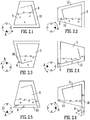
- a further apparatus which facilitates efficient separation of cleaning particles from the cleaned substrate at the conclusion of the cleaning operation, and which comprises a perforated drum and a removable outer drum skin which is adapted to prevent the ingress or egress of fluids and solid particulate matter from the interior of the drum, the cleaning method requiring attachment of the outer skin to the drum during a wash cycle, after which the skin is removed prior to operating a separation cycle to remove the cleaning particles, following which the cleaned substrate is removed from the drum.
- the polymeric particle-based cleaning method, and the separation of said cleaning particles from the cleaned substrate are both further improved by careful control of polymeric particle size, shape and density, as well as process parameters.
- a cleaning process is achieved which facilitates excellent cleaning performance at surprisingly low cleaning temperatures (i.e. low energy), and with reduced levels of added detergents, whilst also maintaining the original low water consumption.
- WO-A-2012/056252 a process has been developed which meets the previously discussed targets for savings in energy consumption, water usage and detergent dosage whilst also facilitating reduced localised fabric damage in the washed substrate by virtue of the increased uniformity of the mechanical action of the particles with the fabric surface.
- a method for the cleaning of a soiled substrate which allows for the use of non-polymeric cleaning particles, and comprises treating the substrate with the non-polymeric particles and wash water in an apparatus comprising a drum comprising perforated side walls, wherein the solid particulate cleaning material may comprises a multiplicity of polymeric and non-polymeric particles.
- the present invention attempts to solve, at least in part, one or more of the following problems including: (i) maintaining the required amount of solid particulate material in the cage during cleaning, (ii) efficient separation of the solid particulate material after the cleaning steps, (iii) maintaining or improving cleaning performance, (iv) maintaining or improving fabric care, (v) maintaining or improving the cleaning efficiency per kg of dry substrate, (vi) storage of the solid particulate material, (vii) improved use of non-polymeric solid particulate materials, (viii) allowing the use of two different kinds of solid particulate materials and (ix) providing a simpler more economic cleaning apparatus and method.
- the present invention at least partially solves these problems using an apparatus which is suited to the demands of both industrial and especially domestic cleaning.
- apparatus e.g. washing machines
- Such apparatus can comprise a perforated drum which is adapted to allow the ingress or egress of fluids from the interior of the drum, but wherein the perforations are of such as size as to prevent the ingress and egress of solid particulate matter therethrough.
- the present invention provides an apparatus which comprises of a rotatably mounted cylindrical cage and a means of collecting and storing solid particulate cleaning material therein and a cleaning method wherein the solid particulate cleaning material is released into the wash load during the wash cycle, and thereafter is collected and stored within the rotatably mounted cylindrical cage.
- an apparatus for use in the treatment of substrates using a solid particulate material comprising:
- said solid particulate material comprises a solid particulate cleaning material.
- said rotatably mounted cylindrical cage comprises a drum comprising perforated side walls, wherein said perforations comprise holes having a diameter less than that of the particles of the solid particulate material. Typically, said holes have a diameter no greater than 5.0 mm.
- said perforations permit the ingress and egress of fluids and fine particulate materials of lesser diameter than the holes, but are adapted so as to prevent the egress of solid particulate material having a particle diameter greater than 5.0 mm.
- said perforations comprise holes having a diameter of less than 5.0 mm, most typically less than 3.0 mm. In such embodiments ingress and egress of all solid particulate material is typically prevented.
- said rotatably mounted cylindrical cage comprises a drum comprising solid side walls including no perforations such that, in operation, ingress and egress of any materials from the interior of drum is only possible via said storage means.
- the said storage means comprises at least one compartment comprising a flow path facilitating ingress and egress of fluids and solid particulate material.
- said storage means comprises a plurality of said compartments.
- said compartment or plurality of compartments may be located on at least one inner surface of said rotatably mounted cylindrical cage.
- Embodiments of the invention envisage a plurality of compartments located, typically at equidistant intervals, on the inner circumferential surface of said rotatably mounted cylindrical cage.
- said plurality of compartments may be located on the inner end surface of said rotatably mounted cylindrical cage.
- Said storage means is adapted such that ingress or egress of fluids and solid particulate material is controlled by the direction of rotation of said rotatably mounted cylindrical cage.
- the storage means comprises at least one compartment comprising a flow path facilitating ingress and egress of fluids and solid particulate material, said ingress and egress is dependent on said direction of rotation.
- the present invention also envisages apparatus wherein said storage means is retrofitted to apparatus of the prior art.
- Said access means comprises a hinged door mounted in the casing, which may be opened to allow access to the inside of the cylindrical cage, and which may be closed in order to provide a substantially sealed system.
- the door includes a window.
- said door also includes at least one addition port which facilitates the addition of materials to said rotatably mounted cylindrical cage.
- Said rotatably mounted cylindrical cage may be mounted vertically within said housing means but, more generally, is mounted horizontally within said housing means. Consequently, in typical embodiments of the invention, said access means is located in the front of the apparatus, providing a front-loading facility. When the rotatably mounted cylindrical cage is vertically mounted within the housing means, the access means is located in the top of the apparatus, providing a top-loading facility. However, for the purposes of the further description of the present invention, it will be assumed that said rotatably mounted cylindrical cage is mounted horizontally within said housing means.
- Rotation of said rotatably mounted cylindrical cage is effected by use of drive means, which typically comprises electrical drive means, in the form of an electric motor. Operation of said drive means is effected by drive control means which may be programmed by an operative.
- drive means typically comprises electrical drive means, in the form of an electric motor. Operation of said drive means is effected by drive control means which may be programmed by an operative.
- Said rotatably mounted cylindrical cage is of the size which is to be found in most commercially available washing machines and tumble dryers, and may have a capacity in the region of 10 to 7000 litres.
- Particular embodiments of the invention are concerned with domestic washing machines wherein a typical capacity would be in the region of 30 to 120 litres.
- other embodiments of the invention relate to industrial washer-extractors, wherein capacities anywhere in the range of from 120 to 7000 litres are possible.
- a typical size in this range is that which is suitable for a 50 kg washload
- the drum has a volume of 450 to 650 litres and, in such cases, said cage would generally comprise a cylinder with a diameter in the region of 75 to 120 cm, typically from 90 to 110 cm, and a length of between 40 and 100 cm, typically between 60 and 90 cm.
- the cage will have 10 litres of volume per kg of washload to be cleaned.
- said apparatus is designed to operate in conjunction with soiled substrates and cleaning media comprising a solid particulate material, which is most preferably in the form of a multiplicity of polymeric particles or a mixture of polymeric and non-polymeric particles. These particles are preferably required to be efficiently circulated to promote effective cleaning and the apparatus, therefore, optionally includes circulation means.
- the inner surface of the cylindrical side walls of said rotatably mounted cylindrical cage typically comprises a multiplicity of spaced apart elongated protrusions affixed essentially perpendicularly to said inner surface.
- said apparatus comprises from 3 to 10, most preferably 4, of said protrusions, which are commonly referred to as lifters.
- agitation of the contents of the rotatably mounted cylindrical cage is provided by the action of said lifters on rotation of said cage.
- inventions envisage an apparatus as hereinbefore defined wherein said storage means comprises a plurality of compartments located at equidistant intervals on the inner circumferential surface of said rotatably mounted cylindrical cage.
- said plurality of compartments thereby additionally functions as a plurality of lifters.
- said lifters are adapted so as to store said solid particulate material and to facilitate controlled flow of solid particulate material between said lifter/storage means and the inside of the cylindrical cage.
- said apparatus comprises a storage compartment of essentially equal length to said lifter, and adapted so as to provide a flow path from the compartment through an aperture in said lifter to the inside of said cage.
- said storage compartments are typically arranged in a circular array about the central axis of said cage and each compartment has a relatively large cross sectional areas and small overall depth, such that the arrangement of compartments does not significantly adversely impact the internal volume of the rotatably mounted cylindrical cage.
- Said rotatably mounted cylindrical cage is mounted within said housing means, which, in turn, is connected to standard plumbing features, thereby providing a multiplicity of delivery means, by virtue of which at least water and, optionally, cleaning agents such as surfactants may be introduced into the apparatus.
- Said apparatus may additionally comprise means for circulating air within said housing means, and for adjusting the temperature and humidity therein.
- Said means may typically include, for example, a recirculating fan, an air heater, a water atomiser and/or a steam generator. Additionally, sensing means may also be provided for determining, inter alia, the temperature and humidity levels within the apparatus, and for communicating this information to the drive control means.
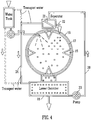
- said apparatus comprises a stationary member which is located adjacent said rotatably mounted cylindrical cage and comprises a multiplicity of delivery means mounted thereon, wherein said multiplicity of delivery means is adapted to facilitate the delivery of materials into said rotatably mounted cylindrical cage.
- said delivery means may comprise spraying means, typically in the form of a spray head, which facilitates better distribution of materials delivered into said rotatably mounted cylindrical cage.
- said rotatably mounted cylindrical cage is located within a first upper chamber of said housing means and beneath said first upper chamber is located a second lower chamber which functions as a sump.
- said apparatus additionally comprises at least one recirculation means, thereby facilitating recirculation of fluids from said lower chamber to said rotatably mounted cylindrical cage.
- said recirculation means comprises pumping means and ducting which connects said lower chamber and said rotatably mounted cylindrical cage.
- soiled garments are first placed into said rotatably mounted cylindrical cage.
- the appropriate mass of solid particulate cleaning material is contained within said storage means before commencement of the washing cycle.
- the necessary amount of water, together with any required additional cleaning agent is added to said rotatably mounted cylindrical cage. via the delivery means or the addition port on the access means.
- These additives may, for example, be pre-mixed with water and optionally heated to the desired temperature.
- pre-mixing and heating may occur in said lower chamber and introduction of the mixture into the rotatably mounted cylindrical cage is effected by means of said recirculation means.
- the rotatably mounted cylindrical cage commences rotation in a pre-determined direction.
- solid particulate cleaning material moves relative to said lifters/storage compartments along the flow paths such that, for each rotation of said cylindrical cage, a volume of solid particulate material is dispensed from said lifters, via the apertures in the lifters, into the soiled garments, until such time that the storage compartments have been emptied.
- the direction of rotation of the cage is, for the most part, maintained for the duration of the wash operation until cleaning is completed.
- the direction of rotation of the cage may be reversed for short periods of time (typically less than 1 minute), in order to improve washing efficiency, principally by untangling soiled garments from each other.
- said rotatably mounted cylindrical cage comprises a drum comprising perforated side walls, wherein said perforations comprise holes having a diameter of no greater than 5.0 mm.
- said perforations permit the ingress and egress of fluids and fine particulate materials, together with solid particulate materials of lesser diameter than the holes, but are adapted so as to prevent the egress of solid particulate material comprising particles of larger diameter.
- said rotatably mounted cylindrical cage is located within a first upper chamber of said housing means and beneath said first upper chamber is located a second lower chamber which functions as a collection chamber for said larger diameter particulate media.
- said lower chamber comprises a sump, which is typically an enlarged sump.
- said apparatus comprises at least one recirculation means, which facilitates recirculation of said larger diameter solid particulate material from said lower chamber to said rotatably mounted cylindrical cage, for re-use in cleaning operations.
- said first recirculation means comprises ducting connecting said second chamber and said rotatably mounted cylindrical cage.
- said ducting comprises separating means for separating said solid particulate material from water and control means, adapted to control entry of said solid particulate material into said cylindrical cage.
- Recirculation of solid particulate matter from said lower chamber to said rotatably mounted cylindrical cage is achieved by the use of pumping means comprised in said first recirculation means, wherein said pumping means is adapted to deliver said solid particulate matter to said separating means and said control means, adapted to control the re-entry of said solid particulate matter into said rotatably mounted cylindrical cage.
- said apparatus additionally includes a second recirculation means, allowing for the return of water separated by said separating means to said lower chamber, thereby facilitating re-use of said water in an environmentally beneficial manner.
- said lower chamber comprises additional pumping means to promote circulation and mixing of the contents thereof, in addition to heating means, allowing the contents to be raised to a preferred temperature of operation.
- said solid particulate material retained in said rotatably mounted cylindrical cage comprises the same material, but having a different particle size, to that which falls into the lower chamber.
- solid particulate material retained in said rotatably mounted cylindrical cage may be comprised of a different material, as well as having a different particle size, to that which falls into the lower chamber.
- this has the advantage of allowing for the use of different particulate materials which demonstrate alternative cleaning performances and these may be used collectively or individually according to the substrate types.
- a method for treating a substrate comprising the treatment of the substrate with a formulation comprising solid particulate material, wherein said method is carried out in an apparatus according to the first aspect of the invention.
- the substrate can comprise at least one soiled substrate and, in typical embodiments, the at least one soiled substrate comprises at least one textile fibre, which is preferably in the form of a garment.
- said method comprises the cleaning of a soiled substrate with a formulation comprising solid particulate cleaning material and wash water, wherein said method is carried out in an apparatus according to the first aspect of the invention.
- said method comprises the steps of:
- additional cleaning agents are employed in said method.
- Said additional cleaning agents are typically pre-mixed with water and the mixture is optionally heated prior to addition to said cylindrical cage via delivery means or an addition port located on said access means.
- said addition may be effected via spraying means, such as a spray head, in order to better distribute said cleaning agents in the washload.
- G is a function of the cage size and the speed of rotation of the cage and, specifically, is the ratio of the centripetal force generated at the inner surface of the cage to the static weight of the washload.
- a cylindrical drum having a diameter of 98 cm is rotated at a speed of 30-800 rpm in order to generate G forces of 0.49-350.6 at different stages during the cleaning process.
- a 48 cm diameter drum rotating at 1600 rpm can generate 687 G, whilst a 60 cm diameter drum at the same speed of rotation generates 859 G.
- the claimed method additionally provides for separation and recovery of the solid particulate cleaning material by collection in the storage means located within said rotatably mounted cylindrical cage. Said solid particulate cleaning material may then be re-used in subsequent washes.
- rotation of said rotatably mounted cylindrical cage is preferably caused to occur at rotation speeds such that G is ⁇ 1 which, for a 98 cm diameter cage, requires a rotation speed of up to 42 rpm, with preferred rates of rotation being between 30 and 40 rpm.
- rotation of said rotatably mounted cylindrical cage can be caused to occur at a G force of less than 1 so as to allow for removal of the solid particulate cleaning material, preferably to the storage means.
- the speed of rotation of the cage can initially be increased in order to effect a measure of drying of the cleaned substrate, thereby generating G forces of between 10 and 1000, more specifically between 40 and 400.
- rotation is at a speed of up to 800 rpm in order to achieve this effect.
- the direction of rotation is reversed and the rotation speed is reduced to the speed of the wash cycle so as to allow for collection and storage of said solid particulate cleaning material in said storage means located in said rotatably mounted cylindrical cage.
- said method may additionally comprise a rinsing operation, wherein additional water may be added to said rotatably mounted cylindrical cage, preferably in order to effect complete removal of any additional cleaning agent employed in the cleaning operation.
- Water may be added to said cylindrical cage via said delivery means or said addition port mounted on said access door.
- addition may optionally be carried out by means of a spray head in order to achieve better distribution of the rinsing water in the washload.
- said addition may be achieved by overfilling the second, lower chamber of said apparatus with water such that it enters the first, upper chamber and thereby partially submerges said rotatably mounted cylindrical cage and enters into said cage.
- said rinse cycle may be used for the purposes of substrate treatment, involving the addition of treatment agents such as anti-redeposition additives, optical brighteners, perfumes, softeners and starch to the rinse water.
- treatment agents such as anti-redeposition additives, optical brighteners, perfumes, softeners and starch to the rinse water.
- Said solid particulate cleaning material is optionally subjected to a cleaning operation in said storage means located in said rotatably mounted cylindrical cage by introducing water, optionally together with a cleaning agent such as a surfactant, into said rotatably mounted cylindrical cage, and thereby into said storage means and rinsing said solid particulate material.
- this water may be heated.
- any remaining solid particulate cleaning material on said at least one substrate may be easily removed by shaking the at least one substrate. If necessary, however, further remaining solid particulate cleaning material may be removed by suction means, preferably comprising a vacuum wand.
- said apparatus finds application in methods for the drying of wet substrates, said methods comprising treating the substrates with a solid particulate material at ambient or elevated temperature, said treatments being carried out in an apparatus according to a first aspect of the invention.
- the substrate typically comprises at least one textile fibre, more typically at least one textile fibre garment
- the apparatus according to the invention may be used for the treatment of any of a wide range of substrates including, for example, plastics materials, leather, paper, cardboard, metal, glass or wood.
- said apparatus is principally designed for use in the cleaning of substrates, specifically those comprising a textile fibre, such as textile fibre garments, and has been shown to be particularly successful in achieving efficient cleaning of textile fibres which may, for example, comprise either natural fibres, such as cotton, or man-made and synthetic textile fibres, for example nylon 6,6, polyester, cellulose acetate, or fibre blends thereof.
- the solid particulate cleaning material comprises a multiplicity of polymeric particles or a mixture of polymeric particles and non-polymeric particles.
- the particles are of such a shape and size as to allow for good flowability and intimate contact with the soiled substrate.
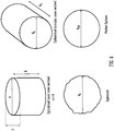
- a variety of shapes of particles can be used, such as cylindrical, spherical or cuboid; appropriate cross-sectional shapes can be employed including, for example, annular ring, dog-bone and circular.
- Non-polymeric particles comprising naturally occurring materials such as stone may have various shapes, dependent on their propensity to cleave in a variety of different ways during manufacture. Most preferably, however, said particles comprise cylindrical or spherical beads.
- the polymeric particles may comprise either foamed or unfoamed polymeric materials. Furthermore, the polymeric particles may comprise polymers which are either linear or crosslinked.
- the polymeric particles typically comprise polyalkenes such as polyethylene and polypropylene, polyamides, polyesters or polyurethanes. More particularly, however, said polymeric particles comprise polyamide or polyester particles, most particularly particles of nylon, polyethylene terephthalate or polybutylene terephthalate, typically in the form of beads. Said polyamides and polyesters are found to be particularly effective for aqueous stain/soil removal, whilst polyalkenes are especially useful for the removal of oil-based stains.
- nylon or polyester homo- or co-polymers may be used including, but not limited to, Nylon 6, Nylon 6,6, polyethylene terephthalate and polybutylene terephthalate.
- the nylon comprises Nylon 6,6 polymer, preferably having a molecular weight in the region of from 5000 to 30000 Daltons, more preferably from 10000 to 20000 Daltons, most preferably from 15000 to 16000 Daltons.
- the polyester will typically have a molecular weight corresponding to an intrinsic viscosity measurement in the range of from 0.3-1.5 dl/g as measured by a solution technique such as ASTM D-4603.
- copolymers of the above polymeric materials may be employed for the purposes of the invention.
- the properties of the polymeric materials may be tailored to specific requirements by the inclusion of monomeric units which confer particular properties on the copolymer.
- the copolymers may be adapted to attract particular staining materials by comprising monomers which, inter alia, are ionically charged, or include polar moieties or unsaturated organic groups.
- the non-polymeric particles may comprise particles of glass, silica, stone, wood, or any of a variety of metals or ceramic materials.
- Suitable metals include, but are not limited to, zinc, titanium, chromium, manganese, iron, cobalt, nickel, copper, tungsten, aluminium, tin and lead, and alloys thereof.
- Suitable ceramics include, but are not limited to, alumina, zirconia, tungsten carbide, silicon carbide and silicon nitride.
- said non-polymeric particles may comprise coated non-polymeric particles.
- said non-polymeric particles may comprise a non-polymeric core material and a shell comprising a coating of a polymeric material.
- said core may comprise a metal core, typically a steel core, and said shell may comprise a polyamide coating, for example a coating of nylon.
- the combination of particle size, shape and density is such that the mechanical action of the particle with the fabric is optimised, it being sufficiently vigorous to provide effective cleaning but, at the same time, uniform and gentle enough to reduce fabric damage when compared with conventional aqueous processes. It is, in particular, the uniformity of the mechanical action generated by the chosen particles across the entire fabric surface that is the key factor in this regard.
- the particle parameters are also controlled so as to allow for easy separation of the particles from the fabric washload at the end of the wash process.
- particle size and shape may be controlled in order to minimise entanglement with the fabric, and the combination of suitable particle density with low G ( ⁇ 1) and high free volume in the washing machine tumbling process together promote particle removal to the storage means located on the inner surface of the rotatably mounted cylindrical cage.
- Non-polymeric particles typically have an average density in the range of from 3.5-12.0 g/cm 3 , more typically from 5.0-10.0 g/cm 3 , most typically from 6.0-9.0 g/cm 3 .
- Polymeric particles typically have an average density in the range of 0.5-2.5 g/cm 3 , more typically from 0.55-2.0 g/cm 3 , most typically from 0.6-1.9 g/cm 3 .
- the average volume of both the non-polymeric and polymeric particles is typically in the range of 5-275 mm 3 , more typically from 8-140 mm 3 , most typically from 10-120 mm 3 .
- the major cross section axis length, a is typically in the range of from 2.0-6.0 mm, more typically from 2.2-5.0 mm, most typically from 2.4-4.5 mm
- the minor cross section axis length, b is typically in the range of from 1.3-5.0 mm, more typically from 1.5-4.0 mm, and most typically from 1.7-3.5 mm (a > b).
- the length of such particles, h is typically from 1.5-6.0 mm, more typically from 1.7-5.0 mm, and most typically from 2.0-4.5 mm (h/b is typically in the range of from 0.5-10).
- the typical cross section diameter, d c is in the range of from 1.3-6.0 mm, more typically from 1.5-5.0 mm, and most typically from 1.7-45.5 mm.
- the typical length, h c , of such particles is again from 1.5-6.0 mm, more typically from 1.7-5.0 mm, and most typically from 2.0-4.5 mm (h c /d c is typically in the range of from 0.5-10).
- the diameter, d s is typically in the range of from 2.0-8.0 mm, more typically in the range of from 2.2-5.5 mm, and most typically from 2.4-5.0 mm.
- the diameter, d ps is typically in the range of from 2.0-8.0 mm, more typically from 3.0-7.0 mm, and most typically from 4.0-6.5 mm.
- particle type polymeric and non-polymeric, when used
- particle size, shape, mass and material must all be considered carefully in respect of the particular substrate which is to be cleaned, so that particle selection is dependent on the nature of the garments to be cleaned, i.e. whether they comprise cotton, polyester, polyamide, silk, wool, or any of the other common textile fibres or blends which are commonly in use.
- the soiled substrate may be moistened by wetting with mains or tap water prior to loading into the apparatus of the invention.
- water is added to the rotatably mounted cylindrical cage of the apparatus according to the invention such that the washing treatment is carried out so as to achieve a water to substrate ratio which is typically between 2.5:1 and 0.1:1 w/w; more typically, the ratio is between 2.0:1 and 0.8:1, with particularly favourable results having been achieved at ratios such as 1.75:1, 1.5:1, 1.2:1 and 1.1:1.
- the required amount of water is introduced into the rotatably mounted cylindrical cage of the apparatus according to the invention after loading of the soiled substrate into said cage.
- the method of the invention envisages the cleaning of a soiled substrate by the treatment of a moistened substrate with a formulation which essentially consists only of a multiplicity of polymeric particles or a multiplicity of polymeric and non-polymeric particles in the absence of any further additives
- the formulation employed may additionally comprise at least one cleaning agent.
- Said at least one cleaning agent may typically comprise at least one detergent composition.
- said at least one cleaning agent is mixed with said polymeric particles or mixture of polymeric and non-polymeric particles but, in a particular embodiment, each of said polymeric particles is coated with said at least one cleaning agent.
- the principal components of the detergent composition comprise cleaning components and post-treatment components.
- the cleaning components comprise surfactants, enzymes and bleach
- the post-treatment components include, for example, anti-redeposition additives, perfumes and optical brighteners.
- the detergent formulation may optionally include one or more other additives such as, for example builders, chelating agents, dye transfer inhibiting agents, dispersants, enzyme stabilizers, catalytic materials, bleach activators, polymeric dispersing agents, clay soil removal agents, suds suppressors, dyes, structure elasticizing agents, fabric softeners, starches, carriers, hydrotropes, processing aids and/or pigments.
- additives such as, for example builders, chelating agents, dye transfer inhibiting agents, dispersants, enzyme stabilizers, catalytic materials, bleach activators, polymeric dispersing agents, clay soil removal agents, suds suppressors, dyes, structure elasticizing agents, fabric softeners, starches, carriers, hydrotropes, processing aids and/or pigments.
- Suitable surfactants may be selected from non-ionic and/or anionic and/or cationic surfactants and/or ampholytic and/or zwitterionic and/or semi-polar nonionic surfactants.
- the surfactant is typically present at a level of from about 0.1%, from about 1%, or even from about 5% by weight of the cleaning compositions to about 99.9%, to about 80%, to about 35%, or even to about 30% by weight of the cleaning compositions.
- compositions may include one or more detergent enzymes which provide cleaning performance and/or fabric care benefits.
- suitable enzymes include, but are not limited to, hemicellulases, peroxidases, proteases, other cellulases, other xylanases, lipases, phospholipases, esterases, cutinases, pectinases, keratanases, reductases, oxidases, phenoloxidases, lipoxygenases, ligninases, pullulanases, tannases, pentosanases, malanases, [beta]-glucanases, arabinosidases, hyaluronidase, chondroitinase, laccase, and amylases, or mixtures thereof.
- a typical combination may comprise a mixture of enzymes such as protease, lipase, cutinase and/or cellulase in conjunction with amylase.
- enzyme stabilisers may also be included amongst the cleaning components.
- enzymes for use in detergents may be stabilised by various techniques, for example by the incorporation of water-soluble sources of calcium and/or magnesium ions in the compositions.
- compositions may include one or more bleach compounds and associated activators.
- bleach compounds include, but are not limited to, peroxygen compounds, including hydrogen peroxide, inorganic peroxy salts, such as perborate, percarbonate, perphosphate, persilicate, and mono persulphate salts (e.g. sodium perborate tetrahydrate and sodium percarbonate), and organic peroxy acids such as peracetic acid, monoperoxyphthalic acid, diperoxydodecanedioic acid, N,N'-terephthaloyl-di(6-aminoperoxycaproic acid), N,N'-phthaloylaminoperoxycaproic acid and amidoperoxyacid.
- Bleach activators include, but are not limited to, carboxylic acid esters such as tetraacetylethylenediamine and sodium nonanoyloxybenzene sulphonate.
- Suitable builders may be included in the formulations and these include, but are not limited to, the alkali metal, ammonium and alkanolammonium salts of polyphosphates, alkali metal silicates, alkaline earth and alkali metal carbonates, aluminosilicates, polycarboxylate compounds, ether hydroxypolycarboxylates, copolymers of maleic anhydride with ethylene or vinyl methyl ether, 1,3,5-trihydroxybenzene-2,4,6-trisulphonic acid, and carboxymethyl-oxysuccinic acid, various alkali metal, ammonium and substituted ammonium salts of polyacetic acids such as ethylenediamine tetraacetic acid and nitrilotriacetic acid, as well as polycarboxylates such as mellitic acid, succinic acid, oxydisuccinic acid, polymaleic acid, benzene 1,3,5-tricarboxylic acid, carboxymethyloxysuccinic acid,
- compositions may also optionally contain one or more copper, iron and/or manganese chelating agents and/or one or more dye transfer inhibiting agents.
- Suitable polymeric dye transfer inhibiting agents include, but are not limited to, polyvinylpyrrolidone polymers, polyamine N-oxide polymers, copolymers of N-vinylpyrrolidone and N-vinylimidazole, polyvinyloxazolidones and polyvinylimidazoles or mixtures thereof.
- the detergent formulations can also contain dispersants.
- Suitable water-soluble organic materials are the homo- or co-polymeric acids or their salts, in which the polycarboxylic acid may comprise at least two carboxyl radicals separated from each other by not more than two carbon atoms.
- Said anti-redeposition additives are physico-chemical in their action and include, for example, materials such as polyethylene glycol, polyacrylates and carboxy methyl cellulose.
- compositions may also contain perfumes Suitable perfumes are generally multi-component organic chemical formulations which can contain alcohols, ketones, aldehydes, esters, ethers and nitrile alkenes, and mixtures thereof.
- Commercially available compounds offering sufficient substantivity to provide residual fragrance include Galaxolide (1,3,4,6,7,8-hexahydro-4,6,6,7,8,8-hexamethylcyclopenta(g)-2-benzopyran), Lyral (3- and 4-(4-hydroxy-4-methyl-pentyl) cyclohexene-1-carboxaldehyde and Ambroxan ((3aR,5aS,9aS,9bR)-3a,6,6,9a-tetramethyl-2,4,5,5a,7,8,9,9b-octahydro-1H-benzo[e][1] benzofuran).
- One example of a commercially available fully formulated perfume is Amour Japonais supplied by Symrise® AG.
- Suitable optical brighteners fall into several organic chemical classes, of which the most popular are stilbene derivatives, whilst other suitable classes include benzoxazoles, benzimidazoles, 1,3-diphenyl-2-pyrazolines, coumarins, 1,3,5-triazin-2-yls and naphthalimides.
- Examples of such compounds include, but are not limited to, 4,4'-bis[[6-anilino-4(methylamino)-1,3,5-triazin-2-yl]amino]stilbene-2,2'-disulphonic acid, 4,4'-bis[[6-anilino-4-[(2-hydroxyethyl)methylamino]-1,3,5-triazin-2-yl]amino]stilbene-2,2'- disulphonic acid, disodium salt, 4,4'-Bis[[2-anilino-4-[bis(2-hydroxyethyl)amino]-1,3,5-triazin-6-yl]amino]stilbene-2,2'-disulphonic acid, disodium salt, 4,4'-bis[(4,6-dianilino-1,3,5-triazin-2-yl)amino]stilbene-2,2'-disulphonic acid, disodium salt, 7-diethylamino-4-methylcoumarin, 4,4
- Said agents may be used either alone or in any desired combination and may be added to the cleaning system at appropriate stages during the cleaning cycle in order to maximise their effects.
- the ratio of solid particulate cleaning material to substrate is generally in the range of from 0.1:1 to 10:1 w/w, more typically in the region of from 0.5:1 to 5:1 w/w, with particularly favourable results being achieved with a ratio of between 1:1 and 3:1 w/w, and especially at around 2:1 w/w.
- 10 g of polymeric particles, optionally coated with surfactant would be employed in one embodiment of the invention.
- the ratio of solid particulate cleaning material to substrate is maintained at a substantially constant level throughout the wash cycle.
- the apparatus and the method of the present invention may be used for either small or large scale batchwise processes and find application in industrial and, most particularly, domestic cleaning processes.
- small scale in this context is typically meant less than or equal to 220 washing cycles per year, whilst large scale typically means more than 220 washing cycles per year.
- the method of the invention finds particular application in the cleaning of textile fibres.
- the conditions employed in such a cleaning system do, however, allow the use of significantly reduced temperatures from those which typically apply to the conventional wet cleaning of textile fabrics and, as a consequence, offer significant environmental and economic benefits.
- typical procedures and conditions for the wash cycle require that fabrics are generally treated according to the method of the invention at, for example, temperatures of between 5 and 95°C, typically for a duration of between 5 and 120 minutes in a substantially sealed system. Thereafter, additional time is required for the completion of the rinsing and bead separation stages of the overall process, so that the total duration of the entire cycle is typically in the region of 1 hour.
- the preferred operating temperatures for the method of the invention are in the range of from 10 to 60°C and, more preferably, from 15 to 40°C.
- the cycle for collection and storage of solid particulate material may optionally be performed at room temperature and it has been established that optimum results are achieved at cycle times of between 2 and 30 minutes, preferably between 5 and 20 minutes.
- the method of the invention also shows benefits in terms of reducing washing-related fabric damage.
- fabric creasing readily occurs in conventional aqueous washing, and this acts to concentrate the stresses from the mechanical action of the wash at each crease, resulting in localised fabric damage.
- Prevention of such fabric damage (or fabric care) is of primary concern to the domestic consumer and industrial user.
- the use of polymeric particles, or mixtures of non-polymeric and polymeric particles, according to the method of the invention effectively reduces creasing in the wash by acting as a pinning layer on the fabric surface in order to help prevent the folding action.
- the particles also inhibit interaction between separate pieces of fabric in the wash by acting as a separation or spacing layer, thereby reducing entanglement which is another major cause of localised fabric damage.
- mechanical action is still present but, critically, this is much more uniformly distributed as a result of the action of the particles. It is the localised aspect of the damage that determines the lifetime of a garment under multiple washing.
- said apparatus finds application in methods for the drying of wet substrates, said methods comprising treating the substrates with a solid particulate material at ambient or elevated temperature, said treatments being carried out in an apparatus according to a first aspect of the invention.
- the method finds particular application in the drying of textile fabrics.
- the conditions employed in such systems allow the use of significantly reduced temperatures from those which typically apply to the conventional tumble drying of textile fabrics and, as a consequence, offer significant environmental and economic benefits.
- typical procedures and conditions for the drying cycle require that fabrics are generally treated according to the method of the invention at, for example, temperatures of between 20 and 80°C for a duration of between 5 and 55 minutes. Thereafter, additional time is required for the completion of the particle separation stage of the overall process, so that the total duration of the entire cycle is typically in the region of 1 hour.
- the method of the invention also shows benefits in terms of reducing drying-related fabric damage.
- fabric creasing readily occurs in conventional tumble drying, and this acts to concentrate the stresses from the mechanical action of the drying process at each crease, resulting in localised fabric damage.
- Prevention of such fabric damage (or fabric care) is of primary concern to the domestic consumer and industrial user.
- the addition of particles according to the method of the invention effectively reduces creasing in the process by acting as a pinning layer on the fabric surface in order to help prevent the folding action.
- the particles also inhibit interaction between separate pieces of fabric in the drying process by acting as a separation or spacing layer, thereby reducing entanglement which is another major cause of localised fabric damage.
- mechanical action is still present but, critically, this is much more uniformly distributed as a result of the action of the particles. It is the localised aspect of the damage that determines the lifetime of a garment under multiple drying processes.
- certain embodiments of the invention provide an apparatus wherein said rotatably mounted cylindrical cage comprises a drum comprising perforated side walls, wherein the side walls comprise perforations comprising holes having a diameter of no greater than 3.0 mm, wherein said perforations permit the ingress and egress of fluids and fine particulate materials of lesser diameter than the holes, but are adapted so as to prevent the egress of said solid particulate material.
- Said embodiments show benefits over prior art systems by requiring a lower mass of solid particulate cleaning material.
- a proportion of the overall mass of solid particulate cleaning material is not interacting with the soiled substrate in the drum, as it is in the respective recirculation means.
- solid particulate cleaning material is retained in the drum at all times, so that a relatively smaller mass of cleaning material can be used.
- alternative embodiments of the present invention provide an apparatus wherein said rotatably mounted cylindrical cage comprises a drum comprising perforated side walls, wherein the perforations comprise holes having a diameter of no greater than 5.0 mm, wherein said perforations permit the ingress and egress of fluids and fine particulate materials, together with solid particulate materials of lesser diameter than the holes, but are adapted so as to prevent the egress of solid particulate material comprising particles of larger diameter.
- Said embodiments additionally comprise recirculation means.
- Said embodiments show benefits over prior art systems by, in the first instance, providing in-drum cleaning material storage means, thereby reducing the storage volume required in the lower chamber and, as such, simplifying the subsequent layout of machine components within the given machine envelope. Furthermore, the provision of separate storage of cleaning material of different specification allows for the individual or collective use of said particles to optimise the cleaning performance in terms of bead mass and cleaning properties to suit particular soiling levels or fabric types. In a further instance, having in-drum cleaning material storage means for use with non-polymeric particles provides a solution to the problem of finding effective storage, since their high density potentially causes difficulties in their use in an apparatus comprising recirculation means.
- rotation of the cage commences in a single direction at around 40 rpm, releasing solid particulate cleaning material (approximately 12.6 kg) from storage means comprised in a series of lifters located in the inner surface of the cylindrical walls of the cage to a washload of soiled substrate (7 kg) in a rotatably mounted cylindrical cage of 48 cm diameter.
- solid particulate cleaning material approximately 12.6 kg
- storage means comprised in a series of lifters located in the inner surface of the cylindrical walls of the cage to a washload of soiled substrate (7 kg) in a rotatably mounted cylindrical cage of 48 cm diameter.
- the solid particulate cleaning material is retained within the rotatably mounted cylindrical cage, where it interacts with the washload of soiled substrate.
- the rate of interaction of the solid particulate cleaning material with the washload is essentially controlled by means of the rotatably mounted cylindrical cage design and rotation.
- the key parameters in this regard include the size and number of lifters, and the speed and direction of the cylindrical cage rotation.
- the perforations are generally sized at a diameter of around 2-3 times less than the average particle diameter of the solid particulate material which, in a typical example, results in perforations having a diameter of no greater than 3.0 mm.
- the method of the invention has been shown to be particularly successful in the removal of cleaning material from the cleaned substrate after washing during tests with nylon beads comprising spherical Nylon 6,6 polymer.
- a series of rinses is typically carried out, wherein additional water is sprayed into the rotatably mounted cylindrical cage, preferably in order to effect complete removal of any additional cleaning agent employed in the cleaning operation.
- a spray head is used, and this may be mounted in an addition port on the access door. The use of such a spray head has been shown to better distribute the rinsing water in the washload and, by this means, the overall water consumption during the rinsing operation can also be minimised (3:1 rinse water:cloth, typically, per rinse).
- FIG. 1 an apparatus according to the invention comprising housing means (1) having a first upper chamber having mounted therein a rotatably mounted cylindrical cage in the form of drum (2) (perforations not shown) and a second lower chamber comprising sump (3) located beneath said cylindrical cage.
- the apparatus additionally comprises water circulation means including water riser pipe (4) which feeds from the lower chamber to an entry point (5) on the top of said rotatably mounted cylindrical cage.
- the water circulation means is driven by a pump (6).
- the apparatus also comprises, for the purpose of example, a multiplicity of lifters (7) comprising storage means for solid particulate material.
- Figure 1 illustrates an embodiment of the invention wherein the solid particulate cleaning material in the form of beads is stored in the lifters (7) until rotation is imposed on the rotatably mounted cylindrical cage (2), wherein the beads are released from the lifters (7) and into the cage (2).
- the rotatably mounted cylindrical cage comprises a drum comprising perforated side walls, wherein the perforations permit the ingress and egress of fluids and fine particulate materials of lesser diameter than the holes, but are adapted so as to prevent the egress of said solid particulate material. Consequently, said embodiment does not provide for recirculation of said solid particulate material.
- in-drum storage means wherein storage compartment (13) and associated flow path (14) are arranged in a circular array about the central axis of the drum, forming a disc storage means of low depth, suitable for location at the rear back face of the drum.
- an array of eight storage compartments is shown.
- Beads (8) exit or enter the flow path via multiple ports (15) arranged around the circumference of the flow paths.
- the beads (8) are encouraged to collect at the perimeter of the rear of the drum by arranging the rotatably mounted cylindrical cage and housing means with a small inclination from rear to front (typically 5 degrees).
- the release cycle and corresponding collection cycle of the beads follows that described previously in relation to Figure 2 .
- the system provides a means of adding polymeric beads or mixtures of polymeric and non-polymeric beads to a wash load, performing the washing cycle, and then separating the beads from the wash load once the washing cycle is complete.
- the washing process may be conveniently illustrated by describing one complete wash cycle with reference to Figures 1 , 2 and 3 .
- polymeric beads or mixtures of polymeric and non-polymeric beads of the appropriate total mass to affect the desired wash performance are stored in lifters (7) having been collected during a previous cleaning cycle.
- a wash load is placed into the cage (2) through an openable loading door (not shown), which is subsequently closed.
- Cold water, together with optional cleaning agent is added to the system via a port in the lower chamber (3).
- the lower chamber (3), together with its contents (water and cleaning agent), may be heated by heating means contained within the lower chamber (3).
- the system temperature is monitored via a temperature probe, preferably mounted in lower chamber (3). Once the required temperature is achieved, the pump (6) pumps the water and cleaning agent up through the riser pipe (4) and cage entry (5) into the cage (2).
- the system then performs a wash cycle in a similar manner to a standard washing machine with the cage (2) rotating at 40 rpm (for a 48 cm cylindrical cage).
- the cage (2) rotates for the majority of the cycle in one direction to ensure full release of all beads, stopping on occasion to rotate a small number of rotations in the opposite direction to minimise tangling of the washload.
- This sequence is repeated for up to 60 minutes. During this time, the beads are continually interacting with the soiled substrate, with only a small proportion of beads collected by the lifters (7) when the direction of rotation of the cage (2) is reversed.
- the cage (2) is rotated for 20 minutes at between 40 and 50 rpm (G ⁇ 1), during which time the direction of rotation is reversed approximately every 3 minutes for 30 seconds in order to re-orientate the substrate and allow the beads to fall from the substrate, thereby effecting efficient bead removal.
- the wash load may be rinsed with water following the wash cycle.
- the beads may be cleaned by filling the sump with clean water in the presence or absence of a cleaning agent, such as a surfactant, to such a level that, on rotation of the drum, lifters and beads contained therein are submerged.
- cleaning of the beads may be carried out by washing them alone in the drum following removal of the wash load.
- the apparatus comprising housing means having a first upper chamber (16) having mounted therein a rotatably mounted cylindrical cage in the form of drum (17) (perforations not shown) and a second lower chamber comprising sump (18) located beneath said cylindrical cage.
- the apparatus also comprises, for the purpose of example, a multiplicity of lifters (19) comprising storage means for solid particulate material.
- the apparatus additionally comprises, as first recirculation means, bead and water riser pipe (20) which feeds into a bead separation vessel (21), including filter material, typically in the form of a wire mesh, and a bead delivery tube (22).
- the first recirculation means is driven by bead pump (23).
- Additional recirculation means comprises return water pipe (24), which allows water to return from the bead separation vessel (21) to the sump (18) under the influence of gravity.
- the apparatus also comprises access means, through which material for cleaning may be loaded into the drum (17).
- the rotatably mounted cylindrical cage comprises a drum comprising perforated side walls, wherein the perforations permit the ingress and egress of fluids and fine particulate materials, together with solid particulate materials of lesser diameter than the holes, but are adapted so as to prevent the egress of solid particulate material comprising particles of larger diameter.
- Said apparatus additionally comprises recirculation means and, consequently, said embodiment provides for recirculation of said solid particulate material.
- the in-drum beads storage means collection and release operation proceeds according to the method previously described in relation to Figures 1 , 2 and 3 , and this process operates in conjunction with the bead recirculation operation which is fully disclosed in connection with the operation of the apparatus disclosed in WO-A-2011/098815 .
- FIG. 6 there is provided a diagrammatic representation of different cylindrical and spherical particles which may be utilised in the method of the invention.
- Cylindrical dry beads (average dimensions: long axis diameter 4.22 mm, short axis diameter 3.5 mm, height 3.97 mm) of SABIC® PP (polypropylene) grade 575P were added to the drum of a washing machine according to the invention which incorporated storage compartments in the lifters on the inner surface of the drum.
- the drum was rotated in clockwise rotation until no further beads were collected by the lifters.
- Surplus beads in the drum were removed, and the drum was then rotated in an anti-clockwise direction until all the beads had been emptied from the lifters.
- the beads released in this manner from the lifters were then collected by vacuum and weighed, and the bulk volume was defined.
- a wash load was rinsed and spun in a BEKO® domestic washing machine (Model WM5120W), then weighed to check its water content. Beads were then mixed with the damp wash load in a large container, and the wash load and beads were loaded into the drum of the apparatus of the invention, which was then operated for an 11 minute cycle which comprised a 3 minute clockwise cycle, a 1 minute anti-clockwise cycle, a further 3 minute clockwise cycle, a 1 minute anti-clockwise cycle and a final 3 minute clockwise cycle. The wash load was then removed from the drum and the beads were separated from the cloth and added to the beads sitting in the drum. All beads where then weighed.
- the empty drum was run on an anti-clockwise cycle to empty the lifters of beads, and these beads were then vacuumed up and weighed.
- Example 1 The procedure of Example 1 was repeated using spherical Nylon 6,6 beads of diameter 4.5 mm (as supplied by Hoover® Precision Products), and the following results were observed: Mass of Dry Wash Load 3 kg Mass of Wash Load after Rinse and Spin 4.57 kg Bead Mass 3.6 kg Bead Volume 5.3 L Bead Mass in Clothes/Drum after Cycle 0.02 kg Bead Mass recovered from Lifters after Cycle 3.58 kg Bead Mass trapped underneath Lifters 0 kg % Beads captured in Lifters during Cycle 99.4% Mass of Beads not captured by Lifters 0.02 kg Number of Beads per kg 18140 Number of Beads not captured by Lifters 363
- Example 1 The procedure of Example 1 was repeated using cylindrical PET 1101 beads (average dimensions: long axis diameter 3.01 mm, short axis diameter 2.23 mm, height 2.11 mm - as supplied by INVISTA® Polymer & Resins) and the following results were observed: Mass of Dry Wash Load 3.08 kg Mass of Wash Load after Rinse and Spin 4.65 kg Bead Mass 4.86 kg Bead Volume 5.3 L Bead Mass in Clothes/Drum after Cycle 0.097 kg Bead Mass recovered from Lifters after Cycle 4.67 kg Bead Mass trapped underneath Lifters 0 kg % Beads captured in Lifters during Cycle 96.1% Mass of Beads not captured by Lifters 0.12 kg Number of Beads per kg 63261 Number of Beads not captured by Lifters 7465
Claims (15)
- Vorrichtung zur Verwendung bei der Behandlung von Substraten unter Verwendung eines festen teilchenförmigen Materials, wobei die Vorrichtung umfasst:(a) ein Gehäusemittel (1), das darin montiert einen drehbar montierten zylindrischen Käfig (2, 17) aufweist;(b) ein Zugangsmittel, das eine scharnierverbundene Tür umfasst, die in dem Gehäuse montiert ist; und(c) eine Mehrzahl von Abgabemitteln, durch die mindestens Wasser und gegebenenfalls Reinigungsmittel in die Vorrichtung eingeführt werden können;
dadurch gekennzeichnet, dass der genannte drehbar montierte zylindrische Käfig (2, 17) zusätzlich ein Speichermittel umfasst, wobei das Speichermittel dafür geeignet ist, das Speichern des genannten festen teilchenförmigen Materials zu erleichtern, und wobei das genannte Speichermittel derart geeignet ist, dass der Eintritt oder Austritt von Fluids und festem teilchenförmigen Material durch die Drehrichtung des genannten drehbar montierten zylindrischen Käfigs gesteuert wird,
wobei das Speichermittel mindestens ein Abteil (9, 13) umfasst, das einen Strömungsweg (10, 14) umfasst, der den genannten Eintritt und Austritt von Fluids und festem teilchenförmigen Material erleichtert. - Vorrichtung nach Anspruch 1, wobei das Speichermittel eine Vielzahl der genannten Abteile (9, 13) umfasst.
- Vorrichtung nach einem der vorhergehenden Ansprüche, wobei das genannte Abteil (9, 13) oder die Vielzahl von Abteilen (9, 13) an mindestens einer Innenfläche des genannten drehbar montierten zylindrischen Käfigs (2, 17) angeordnet ist.
- Vorrichtung nach einem der vorhergehenden Ansprüche, wobei eine Vielzahl von Abteilen (9, 13) entweder in abstandsgleichen Intervallen auf der Innenumfangsfläche des genannten drehbar montierten zylindrischen Käfigs (2, 17) oder auf der Innenendfläche des genannten drehbar montierten zylindrischen Käfigs (2, 17) angeordnet ist.
- Vorrichtung nach einem der vorhergehenden Ansprüche, wobei das Speichermittel in beabstandeten Hebern (7, 19) umfasst ist, die an der Innenfläche des genannten drehbar montierten zylindrischen Käfigs (2, 17) befestigt sind.
- Vorrichtung nach einem der vorhergehenden Ansprüche, wobei der genannte drehbar montierte zylindrische Käfig (2, 17) eine Trommel umfasst, die feste Seitenwände ohne Perforierungen umfasst.
- Vorrichtung nach einem der vorhergehenden Ansprüche, wobei der genannte drehbar montierte zylindrische Käfig (2, 17) innerhalb einer ersten oberen Kammer (16) des Gehäusemittels (1) angeordnet ist, und die genannte Vorrichtung zusätzlich eine zweite untere Kammer umfasst, die einen Sumpf (3, 18) umfasst.
- Vorrichtung nach Anspruch 7, wobei der genannte drehbar montierte zylindrische Käfig perforierte Seitenwände umfasst, in denen die Perforierungen Löcher mit einem kleineren Durchmesser als jenem der Teilchen des genannten festen teilchenförmigen Materials umfassen.
- Vorrichtung nach Anspruch 7, wobei der genannte drehbar montierte zylindrische Käfig (2, 17) eine Trommel umfasst, die perforierte Seitenwände mit Perforierungen mit einem Durchmesser von nicht mehr als 5,0 mm umfasst.
- Verfahren zur Behandlung eines Substrats, wobei das genannte Verfahren die Behandlung des Substrats mit einer Formulierung umfasst, die festes teilchenförmiges Material umfasst, wobei das genannte Verfahren in einer Vorrichtung nach einem der Ansprüche 1 bis 9 vorgenommen wird.
- Verfahren nach Anspruch 10, wobei das genannte Verfahren das Reinigen mindestens eines Substrats umfasst, das mindestens ein verschmutztes Substrat umfasst, und wobei gegebenenfalls das mindestens eine verschmutzte Substrat mindestens ein Textilfaserkleidungsstück umfasst.
- Verfahren nach Anspruch 10 oder 11, wobei das genannte Verfahren in einer Vorrichtung nach Anspruch 1 vorgenommen wird, wobei der genannte drehbar montierte zylindrische Käfig (2, 17) innerhalb einer ersten oberen Kammer (16) des Gehäusemittels (1) der genannten Vorrichtung angeordnet ist, und unterhalb der genannten ersten oberen Kammer (16) eine zweite untere Kammer angeordnet ist, wobei die genannte Vorrichtung ein Rezirkulationsmittel aufweist, wobei das genannte Verfahren die Schritte umfasst:(a) Einführen von Wasser in die zweite untere Kammer der genannten Vorrichtung;(b) Erhitzen des genannten Wassers;(c) Laden mindestens eines verschmutzten Substrats in den genannten drehbar montierten zylindrischen Käfig (2, 17) über das Zugangsmittel;(d) Verschließen des Zugangsmittels, um so ein im Wesentlichen abgedichtetes System bereitzustellen;(e) Einführen des genannten Wassers in den genannten drehbar montierten zylindrischen Käfig (2, 17) über das Rezirkulationsmittel;(f) Betreiben der Vorrichtung für einen Waschzyklus, wobei bewirkt wird, dass sich der genannte drehbar montierte zylindrische Käfig (2, 17) dreht, und bewirkt wird, dass das genannte feste teilchenförmige Reinigungsmaterial aus dem genannten Speichermittel in einer Weise abgegeben wird, die von der genannten Drehung des genannten Käfigs (2, 17) gesteuert wird; und(g) Fortsetzen mit Schritten (f), wie erforderlich, um eine Reinigung des verschmutzten Substrats durchzuführen.
- Verfahren nach einem der Ansprüche 10, 11 oder 12, wobei, bei der Vollendung des Waschzyklus, bewirkt wird, dass die Drehung des genannten drehbar montierten zylindrischen Käfigs (2, 17) bei einer G-Kraft von weniger als 1 auftritt, um so die Entfernung des genannten teilchenförmigen Reinigungsmaterials zum Speichermittel zu gestatten.
- Verfahren nach Anspruch 10, wobei das genannte Verfahren ein Trocknen mindestens eines nassen Substrats umfasst, und wobei gegebenenfalls das mindestens eine nasse Substrat mindestens ein Textilfaserkleidungsstück umfasst.
- Verfahren nach einem der Ansprüche 10 bis 14, wobei das Verhältnis von festem teilchenförmigen Material zu Substrat im Bereich von 0,1:1 bis 10:1 w/w liegt, und/oder der Waschzyklus bei Temperaturen zwischen 5 und 95 °C für eine Dauer zwischen 5 und 120 Minuten vorgenommen wird.
Priority Applications (1)
| Application Number | Priority Date | Filing Date | Title |
|---|---|---|---|
| PL14712724T PL2976453T3 (pl) | 2013-03-20 | 2014-03-18 | Nowe urządzenie i sposób czyszczenia |
Applications Claiming Priority (2)
| Application Number | Priority Date | Filing Date | Title |
|---|---|---|---|
| GBGB1305122.2A GB201305122D0 (en) | 2013-03-20 | 2013-03-20 | New cleaning apparatus and method |
| PCT/GB2014/050856 WO2014147391A1 (en) | 2013-03-20 | 2014-03-18 | New cleaning apparatus and method |
Publications (2)
| Publication Number | Publication Date |
|---|---|
| EP2976453A1 EP2976453A1 (de) | 2016-01-27 |
| EP2976453B1 true EP2976453B1 (de) | 2020-05-20 |
Family
ID=48226751
Family Applications (1)
| Application Number | Title | Priority Date | Filing Date |
|---|---|---|---|
| EP14712724.5A Active EP2976453B1 (de) | 2013-03-20 | 2014-03-18 | Neue reinigungsvorrichtung und -verfahren |
Country Status (9)
| Country | Link |
|---|---|
| US (1) | US9850619B2 (de) |
| EP (1) | EP2976453B1 (de) |
| CN (1) | CN105074078B (de) |
| ES (1) | ES2806573T3 (de) |
| GB (1) | GB201305122D0 (de) |
| HK (1) | HK1217982A1 (de) |
| PL (1) | PL2976453T3 (de) |
| TW (1) | TW201501823A (de) |
| WO (1) | WO2014147391A1 (de) |
Families Citing this family (27)
| Publication number | Priority date | Publication date | Assignee | Title |
|---|---|---|---|---|
| CN102154801B (zh) | 2011-01-11 | 2016-08-17 | 海尔集团公司 | 节水滚筒洗衣机及洗衣方法 |
| GB201100627D0 (en) | 2011-01-14 | 2011-03-02 | Xeros Ltd | Improved cleaning method |
| CN102828379B (zh) | 2011-06-15 | 2016-01-06 | 海尔集团公司 | 使用聚合物固体颗粒的洗涤方法 |
| GB201212098D0 (en) | 2012-07-06 | 2012-08-22 | Xeros Ltd | New cleaning material |
| GB201305120D0 (en) | 2013-03-20 | 2013-05-01 | Xeros Ltd | Improved cleaning apparatus and method |
| GB201305121D0 (en) | 2013-03-20 | 2013-05-01 | Xeros Ltd | Improved drying apparatus and method |
| GB201306607D0 (en) | 2013-04-11 | 2013-05-29 | Xeros Ltd | Method for treating an animal substrate |
| GB201319782D0 (en) | 2013-11-08 | 2013-12-25 | Xeros Ltd | Cleaning method and apparatus |
| GB201320784D0 (en) | 2013-11-25 | 2014-01-08 | Xeros Ltd | Improved cleaning Apparatus and method |
| GB201417487D0 (en) | 2014-10-03 | 2014-11-19 | Xeros Ltd | Method for treating an animal substrate |
| GB201418006D0 (en) | 2014-10-10 | 2014-11-26 | Xeros Ltd | Animal skin substrate treatment apparatus and method |
| GB201418007D0 (en) | 2014-10-10 | 2014-11-26 | Xeros Ltd | Animal skin substrate Treatment apparatus and method |
| GB201421293D0 (en) | 2014-12-01 | 2015-01-14 | Xeros Ltd | New cleaning method, apparatus and use |
| WO2016112660A1 (zh) * | 2015-01-12 | 2016-07-21 | 青岛海尔洗衣机有限公司 | 一种洗衣机排水装置、洗衣机及控制方法 |
| GB201513346D0 (en) | 2015-07-29 | 2015-09-09 | Xeros Ltd | Cleaning method, apparatus and use |
| WO2017178832A1 (en) | 2016-04-13 | 2017-10-19 | Xeros Limited | Method of treatment using a solid particulate material and apparatus therefor |
| AR108127A1 (es) | 2016-04-13 | 2018-07-18 | Xeros Ltd | Método y aparato de tratamiento de pieles de animales |
| GB201704736D0 (en) | 2017-03-24 | 2017-05-10 | Xeros Ltd | Treatment apparatus and method |
| GB201704728D0 (en) * | 2017-03-24 | 2017-05-10 | Xeros Ltd | Treatment apparatus and method |
| KR20200096279A (ko) | 2017-12-19 | 2020-08-11 | 제로스 리미티드 | 처리 장치용 필터 |
| IT201800002846A1 (it) * | 2018-02-23 | 2019-08-23 | Roberto Asara | "macchina lava bossoli automatica" |
| GB201811557D0 (en) | 2018-07-13 | 2018-08-29 | Xeros Ltd | Apparatus and method for treating a substrate with solid particles |
| GB201811569D0 (en) * | 2018-07-13 | 2018-08-29 | Xeros Ltd | Apparatus and method for treating subsrtate with solid particles |
| GB201811568D0 (en) | 2018-07-13 | 2018-08-29 | Xeros Ltd | Apparatus and method for treating a substrate with solid particles |
| GB201815678D0 (en) * | 2018-09-26 | 2018-11-07 | Xeros Ltd | Apparatus and method for treating a substrate with solid particles |
| GB2586592A (en) | 2019-08-21 | 2021-03-03 | Xeros Ltd | New filter, filter unit, treatment apparatus, method and use |
| US20230398474A1 (en) | 2020-11-04 | 2023-12-14 | Xeros Limited | Filter unit, textile treatment apparatus and method |
Family Cites Families (112)
| Publication number | Priority date | Publication date | Assignee | Title |
|---|---|---|---|---|
| DE3527724A1 (de) | 1985-08-02 | 1987-02-12 | Licentia Gmbh | Trommelwaschmaschine |
| DE3803195C2 (de) | 1988-02-03 | 1994-08-18 | Bosch Siemens Hausgeraete | Mitnehmerschöpfrippe für eine Waschtrommel |
| SE468345B (sv) | 1991-04-24 | 1992-12-21 | Moelnlycke Ab | Partikelutmatare |
| DE4310006A1 (de) * | 1992-03-30 | 1993-10-28 | Inst Angewandte Forschung Gmbh | Waschmaschine mit einer unperforierten Waschtrommel |
| DE4324624B4 (de) | 1993-07-22 | 2004-06-17 | Hamann, Hans-Jörg | Vorrichtung zur Oberflächenbehandlung von Textilien |
| GB0607047D0 (en) | 2006-04-07 | 2006-05-17 | Univ Leeds | Novel cleaning method |
| US20090276966A1 (en) | 2006-07-06 | 2009-11-12 | Bsh Bosch Und Siemens Hausgerate Gmbh | Washing machine with hollow agitators |
| DE102006031335B4 (de) * | 2006-07-06 | 2011-01-27 | Airbus Operations Gmbh | Verfahren zur Herstellung eines Faserverbundbauteils für die Luft- und Raumfahrt |
| US20080202435A1 (en) | 2007-02-27 | 2008-08-28 | David Nowacek | Ground based wildlife feeder |
| GB0902619D0 (en) * | 2009-02-17 | 2009-04-01 | Xeros Ltd | Cleaning apparatus |
| GB0907943D0 (en) | 2009-05-08 | 2009-06-24 | Xeros Ltd | Novel cleaning method |
| GB2473224A (en) | 2009-09-03 | 2011-03-09 | John Vincent Flanagan | Detergent-less washing machine |
| CN102061588B (zh) | 2009-11-16 | 2014-02-05 | 海尔集团公司 | 洗衣机、洗涤方法及洗衣筒 |
| CN102061589B (zh) | 2009-11-16 | 2012-03-28 | 海尔集团公司 | 洗衣机 |
| GB0920565D0 (en) | 2009-11-24 | 2010-01-06 | Xeros Ltd | Improved cleaning apparatus |
| GB201002245D0 (en) | 2010-02-10 | 2010-03-31 | Xeros Ltd | Improved cleaning apparatus and method |
| GB201006076D0 (en) | 2010-04-12 | 2010-05-26 | Xeros Ltd | Novel cleaning apparatus and method |
| GB201015276D0 (en) | 2010-09-14 | 2010-10-27 | Xeros Ltd | Polymer treatment method |
| GB201015277D0 (en) | 2010-09-14 | 2010-10-27 | Xeros Ltd | Novel cleaning method |
| GB201018318D0 (en) | 2010-10-29 | 2010-12-15 | Xeros Ltd | Improved cleaning method |
| CN102154801B (zh) | 2011-01-11 | 2016-08-17 | 海尔集团公司 | 节水滚筒洗衣机及洗衣方法 |
| GB201100627D0 (en) | 2011-01-14 | 2011-03-02 | Xeros Ltd | Improved cleaning method |
| GB201100918D0 (en) * | 2011-01-19 | 2011-03-02 | Xeros Ltd | Improved drying method |
| CN102817208B (zh) | 2011-06-09 | 2017-03-01 | 塞罗斯有限公司 | 洗涤用固体颗粒及其洗涤方法 |
| CN202323458U (zh) | 2011-06-15 | 2012-07-11 | 海尔集团公司 | 一种颗粒洗衣机的内筒 |
| CN202214631U (zh) | 2011-06-15 | 2012-05-09 | 海尔集团公司 | 一种应用于洗衣机的颗粒流动控制阀 |
| CN202298219U (zh) | 2011-06-15 | 2012-07-04 | 海尔集团公司 | 一种颗粒洗衣机的外筒 |
| CN102425053B (zh) | 2011-06-15 | 2016-04-06 | 海尔集团公司 | 一种颗粒洗衣机的内筒 |
| CN102828379B (zh) | 2011-06-15 | 2016-01-06 | 海尔集团公司 | 使用聚合物固体颗粒的洗涤方法 |
| CN102425055B (zh) | 2011-06-15 | 2016-05-25 | 海尔集团公司 | 一种颗粒洗衣机的外筒 |
| CN202175862U (zh) | 2011-06-15 | 2012-03-28 | 海尔集团公司 | 应用于洗衣机的颗粒储存盒 |
| CN102899848B (zh) | 2011-07-29 | 2016-03-23 | 海尔集团公司 | 滚筒洗衣机及洗涤方法 |
| EP2749684A4 (de) | 2011-08-22 | 2015-01-07 | Haier Group Corp | Waschmaschine und waschverfahren |
| CN102953250B (zh) | 2011-08-22 | 2017-03-01 | 塞罗斯有限公司 | 一种洗衣机及洗涤方法 |
| CN102953249B (zh) | 2011-08-22 | 2016-09-28 | 海尔集团公司 | 滚筒洗衣机及洗涤方法 |
| CN202214633U (zh) | 2011-08-22 | 2012-05-09 | 海尔集团公司 | 一种洗衣机 |
| CN202265714U (zh) * | 2011-08-22 | 2012-06-06 | 海尔集团公司 | 一种洗衣机 |
| CN202359387U (zh) | 2011-09-02 | 2012-08-01 | 海尔集团公司 | 一种颗粒洗滚筒洗衣机 |
| CN102978870B (zh) | 2011-09-06 | 2017-08-29 | 塞罗斯有限公司 | 一种从洗衣容器中回收固体颗粒的方法 |
| CN202298220U (zh) | 2011-09-07 | 2012-07-04 | 海尔集团公司 | 洗衣机内筒和洗衣机 |
| CN202298222U (zh) | 2011-09-21 | 2012-07-04 | 海尔集团公司 | 应用于洗衣机的颗粒流量控制阀 |
| CN202359396U (zh) | 2011-09-26 | 2012-08-01 | 海尔集团公司 | 应用于洗衣机的颗粒储存盒 |
| CN202359389U (zh) | 2011-09-26 | 2012-08-01 | 海尔集团公司 | 洗衣机内筒 |
| CN103031691B (zh) | 2011-09-30 | 2016-05-25 | 海尔集团公司 | 洗衣机及洗涤方法 |
| CN103031693B (zh) | 2011-09-30 | 2017-05-24 | 塞罗斯有限公司 | 洗衣机及洗涤方法 |
| CN103061086B (zh) | 2011-10-20 | 2016-05-25 | 海尔集团技术研发中心 | 一种洗衣机及洗涤方法 |
| CN103061084B (zh) | 2011-10-20 | 2016-04-06 | 海尔集团技术研发中心 | 一种洗衣机及洗涤方法 |
| CN103061087B (zh) | 2011-10-20 | 2016-04-20 | 青岛海日高科模型有限公司 | 一种洗衣机及洗涤方法 |
| CN103061085B (zh) | 2011-10-24 | 2016-12-21 | 海尔集团技术研发中心 | 一种洗衣机及洗涤方法 |
| CN202359388U (zh) | 2011-11-07 | 2012-08-01 | 海尔集团技术研发中心 | 一种洗衣机 |
| CN103103720B (zh) | 2011-11-15 | 2016-08-03 | 海尔集团技术研发中心 | 一种洗衣机和洗涤方法 |
| CN103103721B (zh) | 2011-11-15 | 2016-12-28 | 海尔集团技术研发中心 | 一种洗衣机及洗涤方法 |
| CN202359390U (zh) | 2011-11-21 | 2012-08-01 | 海尔集团技术研发中心 | 洗衣机 |
| CN103161049B (zh) | 2011-12-13 | 2015-11-25 | 海尔集团技术研发中心 | 洗衣机及洗涤方法 |
| CN202401272U (zh) | 2011-12-23 | 2012-08-29 | 青岛海日高科模型有限公司 | 一种洗衣机 |
| CN103173961B (zh) | 2011-12-23 | 2016-04-06 | 青岛海日高科模型有限公司 | 一种洗衣机及洗涤方法 |
| CN103225192B (zh) | 2012-01-31 | 2016-12-14 | 海尔集团技术研发中心 | 一种洗衣机提升筋及使用该提升筋的洗衣机 |
| CN202492706U (zh) | 2012-02-28 | 2012-10-17 | 海尔集团技术研发中心 | 一种可分离的洗衣机内筒及洗衣机 |
| CN202543646U (zh) | 2012-03-05 | 2012-11-21 | 海尔集团技术研发中心 | 洗衣机颗粒储料盒及洗衣机 |
| CN202543652U (zh) | 2012-03-09 | 2012-11-21 | 海尔集团技术研发中心 | 洗衣机喷淋装置及具有该喷淋装置的洗衣机 |
| CN103361934B (zh) | 2012-03-26 | 2016-05-25 | 海尔集团技术研发中心 | 洗衣机中水处理装置、处理方法及洗衣机 |
| CN103361938B (zh) | 2012-03-26 | 2016-05-25 | 海尔集团技术研发中心 | 一种洗衣机中水处理装置、处理方法及洗衣机 |
| CN202543632U (zh) | 2012-04-17 | 2012-11-21 | 海尔集团技术研发中心 | 一种洗衣机提升筋及洗衣机 |
| US20150027173A1 (en) | 2012-04-17 | 2015-01-29 | Haier Group Technique R&D Center | Washing machine drum baffle and washing machine therewith |
| CN202543635U (zh) | 2012-04-24 | 2012-11-21 | 海尔集团技术研发中心 | 一种洗衣机提升筋及洗衣机 |
| CN202913242U (zh) | 2012-05-03 | 2013-05-01 | 海尔集团技术研发中心 | 一种洗衣机的洗涤内筒及具有该内筒的洗衣机 |
| CN203049283U (zh) | 2012-05-03 | 2013-07-10 | 海尔集团技术研发中心 | 一种洗衣机的洗涤内筒及具有该内筒的洗衣机 |
| CN202755221U (zh) | 2012-05-14 | 2013-02-27 | 海尔集团技术研发中心 | 一种洗衣机的洗涤内筒及具有该内筒的洗衣机 |
| CN202755220U (zh) | 2012-05-14 | 2013-02-27 | 海尔集团技术研发中心 | 一种洗衣机 |
| CN202688698U (zh) | 2012-05-22 | 2013-01-23 | 海尔集团技术研发中心 | 洗涤物提升装置及使用了该提升装置的洗衣机 |
| GB201212096D0 (en) | 2012-07-06 | 2012-08-22 | Xeros Ltd | Improved cleaning formulation and method |
| GB201212098D0 (en) | 2012-07-06 | 2012-08-22 | Xeros Ltd | New cleaning material |
| GB201216101D0 (en) | 2012-09-10 | 2012-10-24 | Xeros Ltd | Improved cleaning apparatus and method |
| GB201305120D0 (en) | 2013-03-20 | 2013-05-01 | Xeros Ltd | Improved cleaning apparatus and method |
| GB201305121D0 (en) | 2013-03-20 | 2013-05-01 | Xeros Ltd | Improved drying apparatus and method |
| GB201306607D0 (en) | 2013-04-11 | 2013-05-29 | Xeros Ltd | Method for treating an animal substrate |
| CN103285643B (zh) | 2013-06-21 | 2015-04-22 | 江苏海狮机械集团有限公司 | 绒毛过滤装置 |
| CN203370359U (zh) | 2013-06-21 | 2014-01-01 | 江苏海狮机械集团有限公司 | 绒毛过滤装置 |
| GB201312158D0 (en) | 2013-07-05 | 2013-08-21 | Xeros Ltd | Method of treating a metal substrate |
| GB201312159D0 (en) | 2013-07-05 | 2013-08-21 | Xeros Ltd | Method of treating a metal substrate |
| CN203530718U (zh) | 2013-09-10 | 2014-04-09 | 江苏海狮机械集团有限公司 | 高效快速热交换器 |
| CN103451894B (zh) | 2013-09-10 | 2015-11-25 | 江苏海狮机械集团有限公司 | 热交换器 |
| CN103556432B (zh) | 2013-09-29 | 2016-03-02 | 江苏海狮机械集团有限公司 | 微粒洗衣机中滚筒口的挡料装置 |
| CN203530725U (zh) | 2013-09-29 | 2014-04-09 | 江苏海狮机械集团有限公司 | 用于微粒洗衣机的固液分离器 |
| CN203530723U (zh) | 2013-09-29 | 2014-04-09 | 江苏海狮机械集团有限公司 | 微粒洗衣机中滚筒的喷水装置 |
| CN203530700U (zh) | 2013-09-29 | 2014-04-09 | 江苏海狮机械集团有限公司 | 微粒洗衣机中滚筒口的挡料装置 |
| CN103556434B (zh) | 2013-09-29 | 2015-11-25 | 江苏海狮机械集团有限公司 | 微粒悬浮紊流器 |
| CN103556439A (zh) | 2013-09-29 | 2014-02-05 | 江苏海狮机械集团有限公司 | 用于微粒洗衣机的固液分离器 |
| CN103556436B (zh) | 2013-09-29 | 2015-11-25 | 江苏海狮机械集团有限公司 | 微粒洗衣机中滚筒的喷水装置 |
| CN203530714U (zh) | 2013-09-29 | 2014-04-09 | 江苏海狮机械集团有限公司 | 微粒悬浮紊流器 |
| CN203530695U (zh) | 2013-09-29 | 2014-04-09 | 江苏海狮机械集团有限公司 | 节能减排微粒洗脱机 |
| CN103556431B (zh) | 2013-09-29 | 2016-01-20 | 江苏海狮机械集团有限公司 | 节能减排微粒洗脱机 |
| GB201317557D0 (en) | 2013-10-03 | 2013-11-20 | Xeros Ltd | Improved cleaning apparatus and method |
| GB201317558D0 (en) | 2013-10-03 | 2013-11-20 | Xeros Ltd | Cleaning apparatus |
| GB201319782D0 (en) | 2013-11-08 | 2013-12-25 | Xeros Ltd | Cleaning method and apparatus |
| GB201320784D0 (en) | 2013-11-25 | 2014-01-08 | Xeros Ltd | Improved cleaning Apparatus and method |
| GB201418005D0 (en) | 2014-06-05 | 2014-11-26 | Xeros Ltd | Apparatus and method for recovery of solid particulate material |
| GB201416718D0 (en) | 2014-09-22 | 2014-11-05 | Xeros Ltd | Treatment apparatus and separating device |
| GB201417487D0 (en) | 2014-10-03 | 2014-11-19 | Xeros Ltd | Method for treating an animal substrate |
| GB201418007D0 (en) | 2014-10-10 | 2014-11-26 | Xeros Ltd | Animal skin substrate Treatment apparatus and method |
| GB201418006D0 (en) | 2014-10-10 | 2014-11-26 | Xeros Ltd | Animal skin substrate treatment apparatus and method |
| GB201421293D0 (en) | 2014-12-01 | 2015-01-14 | Xeros Ltd | New cleaning method, apparatus and use |
| US20160197998A1 (en) | 2015-01-02 | 2016-07-07 | Xeros Limited | Monitoring system |
| US20160195409A1 (en) | 2015-01-02 | 2016-07-07 | Xeros Limited | Monitoring system |
| CN105420993A (zh) | 2016-01-13 | 2016-03-23 | 江苏海狮机械集团有限公司 | 节能减排微粒洗脱机 |
| CN205329373U (zh) | 2016-01-13 | 2016-06-22 | 江苏海狮机械集团有限公司 | 节能减排微粒洗脱机 |
| CN205329384U (zh) | 2016-01-13 | 2016-06-22 | 江苏海狮机械集团有限公司 | 具有固液分离功能的微粒洗脱机门 |
| CN105421000A (zh) | 2016-01-13 | 2016-03-23 | 江苏海狮机械集团有限公司 | 具有固液分离功能的微粒洗脱机门 |
| CN205329380U (zh) | 2016-01-13 | 2016-06-22 | 江苏海狮机械集团有限公司 | 微粒洗脱机中的洗涤剂加料装置 |
| CN105420992A (zh) | 2016-01-13 | 2016-03-23 | 江苏海狮机械集团有限公司 | 微粒洗脱机中的微粒循环系统 |
| CN205329374U (zh) | 2016-01-13 | 2016-06-22 | 江苏海狮机械集团有限公司 | 微粒洗脱机中的微粒循环系统 |
| CN105442267A (zh) | 2016-01-13 | 2016-03-30 | 江苏海狮机械集团有限公司 | 微粒洗脱机中的洗涤剂加料装置 |
-
2013
- 2013-03-20 GB GBGB1305122.2A patent/GB201305122D0/en not_active Ceased
-
2014
- 2014-03-18 CN CN201480017077.8A patent/CN105074078B/zh active Active
- 2014-03-18 ES ES14712724T patent/ES2806573T3/es active Active
- 2014-03-18 EP EP14712724.5A patent/EP2976453B1/de active Active
- 2014-03-18 US US14/777,573 patent/US9850619B2/en active Active
- 2014-03-18 WO PCT/GB2014/050856 patent/WO2014147391A1/en active Application Filing
- 2014-03-18 PL PL14712724T patent/PL2976453T3/pl unknown
- 2014-03-20 TW TW103110417A patent/TW201501823A/zh unknown
-
2016
- 2016-05-24 HK HK16105916.2A patent/HK1217982A1/zh unknown
Non-Patent Citations (1)
| Title |
|---|
| None * |
Also Published As
| Publication number | Publication date |
|---|---|
| ES2806573T3 (es) | 2021-02-18 |
| HK1217982A1 (zh) | 2017-01-27 |
| US20160251795A1 (en) | 2016-09-01 |
| TW201501823A (zh) | 2015-01-16 |
| CN105074078B (zh) | 2017-10-03 |
| WO2014147391A1 (en) | 2014-09-25 |
| GB201305122D0 (en) | 2013-05-01 |
| EP2976453A1 (de) | 2016-01-27 |
| US9850619B2 (en) | 2017-12-26 |
| CN105074078A (zh) | 2015-11-18 |
| PL2976453T3 (pl) | 2020-11-16 |
Similar Documents
| Publication | Publication Date | Title |
|---|---|---|
| EP2976453B1 (de) | Neue reinigungsvorrichtung und -verfahren | |
| US9932700B2 (en) | Cleaning apparatus and method | |
| US9803307B2 (en) | Cleaning method | |
| US10081900B2 (en) | Cleaning method including use of solid particles | |
| US9850455B2 (en) | Cleaning method | |
| AU2011214141B2 (en) | Improved cleaning apparatus and method | |
| AU2012206446A1 (en) | Improved cleaning method | |
| US20150252511A1 (en) | Cleaning apparatus and method | |
| WO2014080192A1 (en) | Improved cleaning apparatus and method |
Legal Events
| Date | Code | Title | Description |
|---|---|---|---|
| PUAI | Public reference made under article 153(3) epc to a published international application that has entered the european phase |
Free format text: ORIGINAL CODE: 0009012 |
|
| 17P | Request for examination filed |
Effective date: 20150805 |
|
| AK | Designated contracting states |
Kind code of ref document: A1 Designated state(s): AL AT BE BG CH CY CZ DE DK EE ES FI FR GB GR HR HU IE IS IT LI LT LU LV MC MK MT NL NO PL PT RO RS SE SI SK SM TR |
|
| AX | Request for extension of the european patent |
Extension state: BA ME |
|
| GRAP | Despatch of communication of intention to grant a patent |
Free format text: ORIGINAL CODE: EPIDOSNIGR1 |
|
| DAX | Request for extension of the european patent (deleted) | ||
| INTG | Intention to grant announced |
Effective date: 20160421 |
|
| 17Q | First examination report despatched |
Effective date: 20160701 |
|
| INTC | Intention to grant announced (deleted) | ||
| STAA | Information on the status of an ep patent application or granted ep patent |
Free format text: STATUS: GRANT OF PATENT IS INTENDED |
|
| REG | Reference to a national code |
Ref country code: HK Ref legal event code: DE Ref document number: 1217982 Country of ref document: HK |
|
| GRAP | Despatch of communication of intention to grant a patent |
Free format text: ORIGINAL CODE: EPIDOSNIGR1 |
|
| INTG | Intention to grant announced |
Effective date: 20200226 |
|
| GRAS | Grant fee paid |
Free format text: ORIGINAL CODE: EPIDOSNIGR3 |
|
| GRAA | (expected) grant |
Free format text: ORIGINAL CODE: 0009210 |
|
| STAA | Information on the status of an ep patent application or granted ep patent |
Free format text: STATUS: THE PATENT HAS BEEN GRANTED |
|
| AK | Designated contracting states |
Kind code of ref document: B1 Designated state(s): AL AT BE BG CH CY CZ DE DK EE ES FI FR GB GR HR HU IE IS IT LI LT LU LV MC MK MT NL NO PL PT RO RS SE SI SK SM TR |
|
| REG | Reference to a national code |
Ref country code: GB Ref legal event code: FG4D |
|
| REG | Reference to a national code |
Ref country code: CH Ref legal event code: EP |
|
| REG | Reference to a national code |
Ref country code: DE Ref legal event code: R096 Ref document number: 602014065669 Country of ref document: DE |
|
| REG | Reference to a national code |
Ref country code: AT Ref legal event code: REF Ref document number: 1272665 Country of ref document: AT Kind code of ref document: T Effective date: 20200615 |
|
| REG | Reference to a national code |
Ref country code: NL Ref legal event code: FP |
|
| REG | Reference to a national code |
Ref country code: LT Ref legal event code: MG4D |
|
| PG25 | Lapsed in a contracting state [announced via postgrant information from national office to epo] |
Ref country code: LT Free format text: LAPSE BECAUSE OF FAILURE TO SUBMIT A TRANSLATION OF THE DESCRIPTION OR TO PAY THE FEE WITHIN THE PRESCRIBED TIME-LIMIT Effective date: 20200520 Ref country code: FI Free format text: LAPSE BECAUSE OF FAILURE TO SUBMIT A TRANSLATION OF THE DESCRIPTION OR TO PAY THE FEE WITHIN THE PRESCRIBED TIME-LIMIT Effective date: 20200520 Ref country code: SE Free format text: LAPSE BECAUSE OF FAILURE TO SUBMIT A TRANSLATION OF THE DESCRIPTION OR TO PAY THE FEE WITHIN THE PRESCRIBED TIME-LIMIT Effective date: 20200520 Ref country code: IS Free format text: LAPSE BECAUSE OF FAILURE TO SUBMIT A TRANSLATION OF THE DESCRIPTION OR TO PAY THE FEE WITHIN THE PRESCRIBED TIME-LIMIT Effective date: 20200920 Ref country code: NO Free format text: LAPSE BECAUSE OF FAILURE TO SUBMIT A TRANSLATION OF THE DESCRIPTION OR TO PAY THE FEE WITHIN THE PRESCRIBED TIME-LIMIT Effective date: 20200820 Ref country code: GR Free format text: LAPSE BECAUSE OF FAILURE TO SUBMIT A TRANSLATION OF THE DESCRIPTION OR TO PAY THE FEE WITHIN THE PRESCRIBED TIME-LIMIT Effective date: 20200821 Ref country code: PT Free format text: LAPSE BECAUSE OF FAILURE TO SUBMIT A TRANSLATION OF THE DESCRIPTION OR TO PAY THE FEE WITHIN THE PRESCRIBED TIME-LIMIT Effective date: 20200921 |
|
| PG25 | Lapsed in a contracting state [announced via postgrant information from national office to epo] |
Ref country code: HR Free format text: LAPSE BECAUSE OF FAILURE TO SUBMIT A TRANSLATION OF THE DESCRIPTION OR TO PAY THE FEE WITHIN THE PRESCRIBED TIME-LIMIT Effective date: 20200520 Ref country code: RS Free format text: LAPSE BECAUSE OF FAILURE TO SUBMIT A TRANSLATION OF THE DESCRIPTION OR TO PAY THE FEE WITHIN THE PRESCRIBED TIME-LIMIT Effective date: 20200520 Ref country code: LV Free format text: LAPSE BECAUSE OF FAILURE TO SUBMIT A TRANSLATION OF THE DESCRIPTION OR TO PAY THE FEE WITHIN THE PRESCRIBED TIME-LIMIT Effective date: 20200520 Ref country code: BG Free format text: LAPSE BECAUSE OF FAILURE TO SUBMIT A TRANSLATION OF THE DESCRIPTION OR TO PAY THE FEE WITHIN THE PRESCRIBED TIME-LIMIT Effective date: 20200820 |
|
| REG | Reference to a national code |
Ref country code: AT Ref legal event code: MK05 Ref document number: 1272665 Country of ref document: AT Kind code of ref document: T Effective date: 20200520 |
|
| PG25 | Lapsed in a contracting state [announced via postgrant information from national office to epo] |
Ref country code: AL Free format text: LAPSE BECAUSE OF FAILURE TO SUBMIT A TRANSLATION OF THE DESCRIPTION OR TO PAY THE FEE WITHIN THE PRESCRIBED TIME-LIMIT Effective date: 20200520 |
|
| PG25 | Lapsed in a contracting state [announced via postgrant information from national office to epo] |
Ref country code: SM Free format text: LAPSE BECAUSE OF FAILURE TO SUBMIT A TRANSLATION OF THE DESCRIPTION OR TO PAY THE FEE WITHIN THE PRESCRIBED TIME-LIMIT Effective date: 20200520 Ref country code: EE Free format text: LAPSE BECAUSE OF FAILURE TO SUBMIT A TRANSLATION OF THE DESCRIPTION OR TO PAY THE FEE WITHIN THE PRESCRIBED TIME-LIMIT Effective date: 20200520 Ref country code: DK Free format text: LAPSE BECAUSE OF FAILURE TO SUBMIT A TRANSLATION OF THE DESCRIPTION OR TO PAY THE FEE WITHIN THE PRESCRIBED TIME-LIMIT Effective date: 20200520 Ref country code: RO Free format text: LAPSE BECAUSE OF FAILURE TO SUBMIT A TRANSLATION OF THE DESCRIPTION OR TO PAY THE FEE WITHIN THE PRESCRIBED TIME-LIMIT Effective date: 20200520 Ref country code: AT Free format text: LAPSE BECAUSE OF FAILURE TO SUBMIT A TRANSLATION OF THE DESCRIPTION OR TO PAY THE FEE WITHIN THE PRESCRIBED TIME-LIMIT Effective date: 20200520 |
|
| REG | Reference to a national code |
Ref country code: ES Ref legal event code: FG2A Ref document number: 2806573 Country of ref document: ES Kind code of ref document: T3 Effective date: 20210218 |
|
| REG | Reference to a national code |
Ref country code: DE Ref legal event code: R097 Ref document number: 602014065669 Country of ref document: DE |
|
| PG25 | Lapsed in a contracting state [announced via postgrant information from national office to epo] |
Ref country code: SK Free format text: LAPSE BECAUSE OF FAILURE TO SUBMIT A TRANSLATION OF THE DESCRIPTION OR TO PAY THE FEE WITHIN THE PRESCRIBED TIME-LIMIT Effective date: 20200520 |
|
| PLBE | No opposition filed within time limit |
Free format text: ORIGINAL CODE: 0009261 |
|
| STAA | Information on the status of an ep patent application or granted ep patent |
Free format text: STATUS: NO OPPOSITION FILED WITHIN TIME LIMIT |
|
| 26N | No opposition filed |
Effective date: 20210223 |
|
| PG25 | Lapsed in a contracting state [announced via postgrant information from national office to epo] |
Ref country code: SI Free format text: LAPSE BECAUSE OF FAILURE TO SUBMIT A TRANSLATION OF THE DESCRIPTION OR TO PAY THE FEE WITHIN THE PRESCRIBED TIME-LIMIT Effective date: 20200520 |
|
| PG25 | Lapsed in a contracting state [announced via postgrant information from national office to epo] |
Ref country code: MC Free format text: LAPSE BECAUSE OF FAILURE TO SUBMIT A TRANSLATION OF THE DESCRIPTION OR TO PAY THE FEE WITHIN THE PRESCRIBED TIME-LIMIT Effective date: 20200520 |
|
| REG | Reference to a national code |
Ref country code: CH Ref legal event code: PL |
|
| REG | Reference to a national code |
Ref country code: BE Ref legal event code: MM Effective date: 20210331 |
|
| PG25 | Lapsed in a contracting state [announced via postgrant information from national office to epo] |
Ref country code: IE Free format text: LAPSE BECAUSE OF NON-PAYMENT OF DUE FEES Effective date: 20210318 Ref country code: CH Free format text: LAPSE BECAUSE OF NON-PAYMENT OF DUE FEES Effective date: 20210331 Ref country code: LU Free format text: LAPSE BECAUSE OF NON-PAYMENT OF DUE FEES Effective date: 20210318 Ref country code: LI Free format text: LAPSE BECAUSE OF NON-PAYMENT OF DUE FEES Effective date: 20210331 |
|
| PG25 | Lapsed in a contracting state [announced via postgrant information from national office to epo] |
Ref country code: BE Free format text: LAPSE BECAUSE OF NON-PAYMENT OF DUE FEES Effective date: 20210331 |
|
| PGFP | Annual fee paid to national office [announced via postgrant information from national office to epo] |
Ref country code: FR Payment date: 20230324 Year of fee payment: 10 Ref country code: CZ Payment date: 20230313 Year of fee payment: 10 |
|
| PG25 | Lapsed in a contracting state [announced via postgrant information from national office to epo] |
Ref country code: HU Free format text: LAPSE BECAUSE OF FAILURE TO SUBMIT A TRANSLATION OF THE DESCRIPTION OR TO PAY THE FEE WITHIN THE PRESCRIBED TIME-LIMIT; INVALID AB INITIO Effective date: 20140318 |
|
| PGFP | Annual fee paid to national office [announced via postgrant information from national office to epo] |
Ref country code: TR Payment date: 20230317 Year of fee payment: 10 Ref country code: PL Payment date: 20230222 Year of fee payment: 10 Ref country code: IT Payment date: 20230322 Year of fee payment: 10 Ref country code: GB Payment date: 20230322 Year of fee payment: 10 Ref country code: DE Payment date: 20230321 Year of fee payment: 10 |
|
| P01 | Opt-out of the competence of the unified patent court (upc) registered |
Effective date: 20230516 |
|
| PG25 | Lapsed in a contracting state [announced via postgrant information from national office to epo] |
Ref country code: CY Free format text: LAPSE BECAUSE OF FAILURE TO SUBMIT A TRANSLATION OF THE DESCRIPTION OR TO PAY THE FEE WITHIN THE PRESCRIBED TIME-LIMIT Effective date: 20200520 |
|
| PGFP | Annual fee paid to national office [announced via postgrant information from national office to epo] |
Ref country code: ES Payment date: 20230529 Year of fee payment: 10 |
|
| PGFP | Annual fee paid to national office [announced via postgrant information from national office to epo] |
Ref country code: NL Payment date: 20240320 Year of fee payment: 11 |
|
| PG25 | Lapsed in a contracting state [announced via postgrant information from national office to epo] |
Ref country code: MK Free format text: LAPSE BECAUSE OF FAILURE TO SUBMIT A TRANSLATION OF THE DESCRIPTION OR TO PAY THE FEE WITHIN THE PRESCRIBED TIME-LIMIT Effective date: 20200520 |
|
| PGFP | Annual fee paid to national office [announced via postgrant information from national office to epo] |
Ref country code: DE Payment date: 20240320 Year of fee payment: 11 Ref country code: CZ Payment date: 20240308 Year of fee payment: 11 Ref country code: GB Payment date: 20240320 Year of fee payment: 11 |