EP2975111B1 - Dispositif de mélange d'un contenu d'un récipient - Google Patents
Dispositif de mélange d'un contenu d'un récipient Download PDFInfo
- Publication number
- EP2975111B1 EP2975111B1 EP14002424.1A EP14002424A EP2975111B1 EP 2975111 B1 EP2975111 B1 EP 2975111B1 EP 14002424 A EP14002424 A EP 14002424A EP 2975111 B1 EP2975111 B1 EP 2975111B1
- Authority
- EP
- European Patent Office
- Prior art keywords
- container
- removal
- mixing
- pivot axis
- container support
- Prior art date
- Legal status (The legal status is an assumption and is not a legal conclusion. Google has not performed a legal analysis and makes no representation as to the accuracy of the status listed.)
- Active
Links
- 238000002156 mixing Methods 0.000 title claims description 74
- 230000008878 coupling Effects 0.000 claims description 39
- 238000010168 coupling process Methods 0.000 claims description 39
- 238000005859 coupling reaction Methods 0.000 claims description 39
- 230000007246 mechanism Effects 0.000 claims description 10
- 239000007789 gas Substances 0.000 description 10
- 238000000605 extraction Methods 0.000 description 9
- 239000000969 carrier Substances 0.000 description 4
- 239000012530 fluid Substances 0.000 description 3
- 239000011888 foil Substances 0.000 description 3
- 239000007788 liquid Substances 0.000 description 3
- 238000000034 method Methods 0.000 description 3
- 239000000725 suspension Substances 0.000 description 3
- QVGXLLKOCUKJST-UHFFFAOYSA-N atomic oxygen Chemical compound [O] QVGXLLKOCUKJST-UHFFFAOYSA-N 0.000 description 2
- 238000004113 cell culture Methods 0.000 description 2
- 238000010276 construction Methods 0.000 description 2
- 238000011109 contamination Methods 0.000 description 2
- 238000006073 displacement reaction Methods 0.000 description 2
- 238000004519 manufacturing process Methods 0.000 description 2
- 239000000463 material Substances 0.000 description 2
- 239000002207 metabolite Substances 0.000 description 2
- 244000005700 microbiome Species 0.000 description 2
- 239000001301 oxygen Substances 0.000 description 2
- 229910052760 oxygen Inorganic materials 0.000 description 2
- 230000008569 process Effects 0.000 description 2
- 239000000126 substance Substances 0.000 description 2
- 238000010364 biochemical engineering Methods 0.000 description 1
- 238000011138 biotechnological process Methods 0.000 description 1
- 238000004140 cleaning Methods 0.000 description 1
- 230000001419 dependent effect Effects 0.000 description 1
- 230000008030 elimination Effects 0.000 description 1
- 238000003379 elimination reaction Methods 0.000 description 1
- 238000005516 engineering process Methods 0.000 description 1
- 239000011521 glass Substances 0.000 description 1
- 230000005484 gravity Effects 0.000 description 1
- 239000001963 growth medium Substances 0.000 description 1
- 230000036512 infertility Effects 0.000 description 1
- 238000009434 installation Methods 0.000 description 1
- 230000002503 metabolic effect Effects 0.000 description 1
- 239000000203 mixture Substances 0.000 description 1
- 235000015097 nutrients Nutrition 0.000 description 1
- 238000004062 sedimentation Methods 0.000 description 1
- 238000003892 spreading Methods 0.000 description 1
- 230000007480 spreading Effects 0.000 description 1
- 229910001220 stainless steel Inorganic materials 0.000 description 1
- 239000010935 stainless steel Substances 0.000 description 1
- 238000003756 stirring Methods 0.000 description 1
- 238000003860 storage Methods 0.000 description 1
- 239000013598 vector Substances 0.000 description 1
Images


Classifications
-
- C—CHEMISTRY; METALLURGY
- C12—BIOCHEMISTRY; BEER; SPIRITS; WINE; VINEGAR; MICROBIOLOGY; ENZYMOLOGY; MUTATION OR GENETIC ENGINEERING
- C12M—APPARATUS FOR ENZYMOLOGY OR MICROBIOLOGY; APPARATUS FOR CULTURING MICROORGANISMS FOR PRODUCING BIOMASS, FOR GROWING CELLS OR FOR OBTAINING FERMENTATION OR METABOLIC PRODUCTS, i.e. BIOREACTORS OR FERMENTERS
- C12M23/00—Constructional details, e.g. recesses, hinges
- C12M23/02—Form or structure of the vessel
- C12M23/14—Bags
-
- C—CHEMISTRY; METALLURGY
- C12—BIOCHEMISTRY; BEER; SPIRITS; WINE; VINEGAR; MICROBIOLOGY; ENZYMOLOGY; MUTATION OR GENETIC ENGINEERING
- C12M—APPARATUS FOR ENZYMOLOGY OR MICROBIOLOGY; APPARATUS FOR CULTURING MICROORGANISMS FOR PRODUCING BIOMASS, FOR GROWING CELLS OR FOR OBTAINING FERMENTATION OR METABOLIC PRODUCTS, i.e. BIOREACTORS OR FERMENTERS
- C12M27/00—Means for mixing, agitating or circulating fluids in the vessel
- C12M27/16—Vibrating; Shaking; Tilting
-
- C—CHEMISTRY; METALLURGY
- C12—BIOCHEMISTRY; BEER; SPIRITS; WINE; VINEGAR; MICROBIOLOGY; ENZYMOLOGY; MUTATION OR GENETIC ENGINEERING
- C12M—APPARATUS FOR ENZYMOLOGY OR MICROBIOLOGY; APPARATUS FOR CULTURING MICROORGANISMS FOR PRODUCING BIOMASS, FOR GROWING CELLS OR FOR OBTAINING FERMENTATION OR METABOLIC PRODUCTS, i.e. BIOREACTORS OR FERMENTERS
- C12M23/00—Constructional details, e.g. recesses, hinges
- C12M23/46—Means for fastening
Definitions
- the present invention relates to a mixing device for mixing a content of a container.
- containers are used for mixing or circulating materials.
- culture media for microorganisms or controlled biotechnological processes such as cell cultivation of the mixing or the circulation of the container contents is of particular importance. Due to the different initial concentrations of the substances and the metabolic activity of the microorganisms during cultivation, there are local concentration changes of various chemical components in the media mixture or of nutrients, oxygen and the resulting metabolites during cultivation. In order to ensure the same or at least controlled concentration conditions in the entire container, it is necessary to mix or circulate the liquid or suspension in the container during the entire process.
- stirrerless mixers are known as rockers, platform shakers, tumble mixers, orbital shakers, vibratory shakers, horizontal shakers, orbital shakers, etc.
- Flexible containers may vary in size depending on the application, with larger containers having volumes of several liters.
- the most previously filled containers are usually placed on plate-shaped or trough-shaped movable supports, e.g. be fixed by clamps or hooks or other releasable fasteners on the carriers.
- the carriers are driven and produce the mixing movement of the contents of the container.
- the carrier carries out, for example, a rocking movement about a horizontal position.
- the carriers In order to remove the contents of the bag, the carriers can be moved with the bags fixed thereon in a nearly vertical position. It may also be possible to fill the containers in the vertical position.
- WO 2012/115581 A1 discloses a bioreactor with a mixing device in which a container carrier performs a rocking motion about a horizontal rocking axis for mixing a content of a container.
- a container carrier performs a rocking motion about a horizontal rocking axis for mixing a content of a container.
- an erection axis is arranged, about which the container carrier can be pivoted for setting up the container carrier, wherein the erecting axis is parallel to the rocking axis.
- the container carrier can be inclined in the erected state about a second tilting axis, which is perpendicular to the erection axis, to a corner of the container.
- US 2013/0244322 A1 discloses a bioreactor with a mixing device in which a container carrier performs a rocking motion about a horizontal rocking axis for mixing a content of a container.
- a horizontal erecting axis is arranged, about which the container carrier can be pivoted for setting up the container carrier, wherein the erecting axis is parallel to the rocking axis.
- a mixing apparatus for mixing a contents of a container, comprising: a container carrier for carrying the container; and a moving device connected to move the container carrier with the container carrier to mix the contents of the container in a mixing position; the container carrier having a positioning device adapted to position the container in a predetermined position on the container carrier such that a withdrawal side of the container is disposed substantially along a predetermined line of the container carrier the container carrier is pivotally mounted about a take-off pivot axis relative to the moving device to move the positionable container into a removal position, wherein the removal pivot axis in such a pivot axis angle of about 0 ° to 45 ° to the predetermined line of the container Carrier is arranged so that the positionable container can be moved from the mixing position by means of a pivoting movement of the container carrier to the removal pivot axis in the removal position in which the removal side located on the lower side of the container and to a Removal of the container is inclined.
- the container may, in particular, be a bioreactor container, which may be made of a film material. Such a container can be welded as a bag with at least two opposite sides Be executed edges.
- the container may have a predetermined bearing surface on which the container can be stored stably on a horizontal surface.
- the support surface may in particular be one of its largest surfaces or side surfaces.
- the support surface and / or the surface opposite the support surface may have passages and connections for supply and / or discharge lines and / or sensors. If the supply and / or discharge lines are located on the support surface, the container carrier also has corresponding passages for the connected lines.
- the container can be arranged with its bearing surface on the container carrier.
- the container may have in plan view a substantially quadrangular shape with four side edges.
- the container may be formed symmetrically in plan view, which is advantageous for a uniform movement of the contents of the container during mixing.
- At least the container has a removal side.
- the removal side may be a substantially straight side edge of the container, wherein a side edge of the container interior is meant.
- the withdrawal side refers to the side of the container which is provided for collection and removal of the contents of the container and in particular of the products which have formed in the container.
- the removal area of the container can be arranged in one of the two corners of the removal side. At the removal area, an outlet can be arranged, from which the contents of the container can be omitted.
- the container positioned on the container carrier is displaced together with the container carrier for removal into the removal position.
- a filling of the container is also possible in this position via the supply lines arranged on the container.
- the contents of the container may be a liquid or a suspension.
- the container may further contain a gas or gases.
- the content of the container is mixed or circulated by means of the mixing device, whereby a good oxygen mixing can be ensured in particular during cell cultivation.
- the container carrier is designed such that the container is arranged thereon can be.
- the container carrier may be formed such that the container with its container carrier facing the largest surface or its support surface substantially completely rests against the upper surface of the container carrier.
- the upper surface of the container carrier may be referred to as a receiving surface.
- the container carrier may for example be formed plate-shaped or trough-shaped and executed in the plan view is substantially square. Essentially, the trough-shaped container carriers serve to absorb the escaping fluid from the containers in the event of leaks in the containers. However, there are also trough-shaped container carrier with one or more open corners or openings possible over which the discharge lines are guided in the installation position so as to facilitate removal from the container.
- the size of the container carrier is not limited and may be selected depending on the container size.
- the shape and size of the container carrier in the plan view corresponds substantially to the shape and size of the container in plan view.
- the moving device is configured to move the container carrier to perform the mixing movement.
- the movement device preferably via a movable coupling element, connected to the container carrier.
- the container carrier When moving the container to mix the contents of the container, the container carrier is in a mixing position and the container positioned thereon is in a mixing position. In the mixed position, the container carrier, or the receiving surface thereof, is oriented substantially horizontally. More specifically, in the mixing layer for mixing, the container carrier performs motion around or in the horizontal plane.
- the mixing device may be referred to as rocker, platform shaker, tumble mixer, orbital shaker, vibratory shaker, horizontal shaker, orbital shaker, etc.
- the container carrier performs a tilting or rocking motion about a substantially horizontal axis, with the container carrier initially in a range of about 0-15 °, preferably in a range of about 0-10 °, is inclined to the horizontal plane, and then in the opposite direction in a range of about 0-15 °, preferably in a range of about 0-10 °, is inclined to the horizontal plane.
- This movement of the container carrier is transmitted to the container, so that a wave motion of the Contents of the container can be generated.
- the mixing movement of the container support does not necessarily include inclining to the horizontal plane, and instead the container support may be reciprocated linearly or circularly in the horizontal plane and / or horizontally reciprocated in the vertical direction be shaken.
- the mixed layer is thus changeable by the movement of the container carrier, but is substantially in the horizontal plane or differs only slightly from this.
- the container carrier has a predetermined or predeterminable rest position, which is assumed when the container carrier performs no mixing movement in the mixing position.
- the container disposed on the container carrier In the rest position, the container disposed on the container carrier is in a rest position. In the rest position or rest position, the container carrier or the container is preferably oriented approximately horizontally. The same applies to the mixing position of the arranged on the container carrier container.
- the container carrier has a positioning device, which can be provided in each case on one or more sides of the container carrier.
- the positioning device may have, for example, terminals, clamping rails and / or fastening hooks.
- the positioning device can enable releasable positioning or fixing of the container to the container carrier.
- the positioning device is adapted to position the container in a predetermined position on the container carrier such that the withdrawal side of the container is disposed substantially along a predetermined imaginary line of the container carrier.
- the predetermined line is an imaginary line and does not need to be visible on the container carrier.
- This imaginary line of the container carrier extends the removal side of the container, in particular the substantially straight side edge of the container interior, when the container is positioned by means of the positioning device on the container carrier.
- the predetermined line may be connected to a side edge of the container carrier on the Matching page, or parallel to this.
- the removal pivot axis can also be defined in this case with respect to the side edge of the container carrier, namely that the removal pivot axis at an angle of about 0 ° to 45 °, preferably about 1 ° to about 15 °, more preferably about 3 ° to about 10 °, is arranged to the side edge of the container carrier.
- the predetermined line can also coincide with the extension direction of a clamping rail of the positioning device or run parallel to it.
- the removal pivot axis can also be defined in this case with respect to the extension direction of the clamping rail, namely that the removal pivot axis at an angle of about 0 ° to 45 °, preferably about 1 ° to about 15 °, more preferably about 3 ° is arranged to about 10 °, to the extension direction of the clamping rail.
- the container carrier may have a stop for the removal side of the container, in which case the predetermined line may coincide with the direction of extension of the stop or may be parallel thereto.
- the removal pivot axis can also be defined in this case with respect to the extension direction of the stop, namely that the removal pivot axis at an angle of about 0 ° to 45 °, preferably about 1 ° to about 15 °, more preferably about 3 ° is arranged to about 10 °, to the extension direction of the stop.
- the predetermined line may be parallel to an axis of symmetry of the container carrier.
- the removal pivot axis can also be defined in this case with respect to the symmetry axis of the container carrier, namely that the removal pivot axis at an angle of about 0 ° to 45 °, preferably about 1 ° to about 15 °, more preferably about 3 ° to about 10 °, is arranged to the axis of symmetry of the container carrier.
- the container carrier is pivotally mounted on the moving device and can be pivoted relative to the moving device. This pivoting movement is independent of the mixing movement of the container carrier and is basically not carried out during the mixing movement.
- the pivotability of the container carrier relative to the movement device allows a displacement of the container carrier from the mixing layer into a removal position. Accordingly, the pivotability of the container carrier relative to the movement device allows a displacement of the arranged on the container carrier container from a mixing position to a removal position.
- the shifting from the mixing position or mixing position into the removal position or removal position can also be referred to as "erection".
- the container In the removal position, the container is oriented such that the removal side is located in the vertical direction on the lower side of the container and is inclined to a removal region of the container.
- the removal region may be located in the region of one of the lower corners of the container, wherein the removal region may be located directly in the corner itself or on the upper surface or support surface of the container near the corner.
- the support surface of the container In the removal position, the support surface of the container is inclined at a steep angle to the horizontal plane, and the withdrawal side of the container forms the lower side or edge of the container.
- the withdrawal side of the container is inclined to the horizontal plane, but at a shallower angle.
- the inclination angle of the extraction side to the horizontal plane approximately corresponds to the pivot axis angle between the extraction pivot axis and the predetermined line of the container support.
- the support surface is inclined less than 90 ° to the horizontal plane, the inclination angle of the extraction side to the horizontal plane is less than the pivot axis angle between the extraction pivot axis and the predetermined line of the container support.
- the support surface of the container may be inclined in the removal position at an angle of 30 ° to 90 °, preferably 35 ° to 55 ° to the horizontal plane.
- the receiving surface of the container carrier in the picking position, is inclined at a steep angle to the horizontal plane, and the predetermined line of the container carrier is also to the horizontal plane inclined, but at a shallower angle.
- the inclination angle of the predetermined line to the horizontal plane approximately corresponds to the pivot axis angle between the take-off pivot axis and the predetermined line.
- the inclination angle of the predetermined line to the horizontal plane is less than the pivot axis angle between the unloading pivot axis and the predetermined line.
- the receiving surface of the container carrier may be inclined in the removal position at an angle of 30 ° to 90 °, preferably 35 ° to 55 ° to the horizontal plane.
- the container support (or the receiving surface thereof) is oriented substantially to the horizontal plane, the above explanations regarding the inclinations in relation to the horizontal plane essentially also apply to the inclinations in Relation to the mixed position or rest position.
- the take-off pivot axis is located at a pivot axis angle greater than 0 ° to 45 ° to the predetermined line of the container support, here the smallest angle (ie, an angle between 0 ° and 90 °) between the take-off pivot axis and the predetermined line is. If the extraction pivot axis and the predetermined line do not intersect in space, that is skew, the pivot axis angle is to be determined as the angle between the direction vectors of the extraction pivot axis and the predetermined line. In other words, the pivot axis angle is the largest detectable angle between 0 ° and 90 ° between the projected lines of the extraction pivot axis and the predetermined line on all possible planes in space.
- the pivot axis angle corresponds to the angle between the lines projected on the horizontal plane of the extraction pivot axis and the predetermined line when the container support (or the receiving surface thereof) is aligned to the horizontal plane or if the container carrier in the mixed position or rest position.
- the take-off pivot axis is inclined within the horizontal plane from the predetermined line about the pivot axis angle, and has no inclination to the horizontal plane.
- the container carrier and / or the movement device may have a pivot bearing, which connects the container carrier with the movement device, wherein the pivot axis of the pivot bearing of the removal pivot axis corresponds.
- the oblique arrangement of the removal pivot axis to the predetermined line of the container support that the container carrier and the positionable container can be moved by means of a single pivoting movement in an advantageous removal position or removal position.
- the removal position of the container carrier is placed opposite the horizontal plane.
- the container is preferably mounted and removed in the horizontal position.
- the removal side of the container is inclined to a removal region, so that the removal region is always located at the lowest point of the container.
- the extraction pivot axis is disposed at a pivot axis angle of about 1 ° to about 15 °, more preferably about 3 ° to about 10 °, to the predetermined line.
- a pivot axis angle is particularly advantageous for collecting products in the removal area and for easy positioning of the container on the container carrier.
- the moving device is designed to move the container carrier back and forth about a substantially horizontal rocking axis, wherein the rocking axis is arranged substantially parallel to the predetermined line.
- the container support is first inclined by about 2 ° to 15 ° to the horizontal plane, and then inclined in the opposite direction by about 2 ° to 15 ° to the horizontal plane.
- This movement of the container carrier may be carried out repeatedly and transferred to the container, so that a constant wave movement of the contents of the container can be generated.
- the rocking axis can be predetermined by the movement device.
- the rocking axis is preferably arranged centrally relative to the container carrier or the container positioned thereon so that the distance traveled in the vertical direction of the removal side during the tilting movement corresponds approximately to the distance traveled in the vertical direction of the removal side opposite side of the container.
- the rocking axis may be spaced from the receiving surface of the container carrier in the vertical direction.
- the rocking axis is arranged substantially parallel to the predetermined line, so that the removal pivot axis can also be defined with respect to the rocking axis, namely that the removal pivot axis at an angle of about 0 ° to 45 °, preferably about 1 ° to about 15 °, more preferably about 3 ° to about 10 °, is arranged to Wippachse.
- the movement device comprises a movable coupling element, which is connected for moving the container carrier with the container carrier, wherein the container carrier is pivotally mounted about the removal pivot axis on the coupling element, so that the container carrier by means of a pivoting movement can be moved from a mixed layer into a picking situation.
- the coupling element can be driven or moved by a drive of the movement device.
- the coupling member may project upwardly from a base of the moving device.
- the container carrier is connected via the coupling element with the movement device, so that the movement of the coupling element can be transferred to the container carrier and further to the container.
- the positioning device has at least one clamping rail, which extends substantially along the predetermined line or parallel thereto.
- one side of the container in particular in the case of a foil bag, can be fixed to the container carrier by means of the clamping rail.
- a clamping rail is provided on the withdrawal side of the container and a clamping rail on the side opposite the removal side of the container.
- the container may have at the appropriate locations tabs or rails that can cooperate with the clamping rails.
- the container has in its periphery on at least two sides via tabs inserted into tabs or rods which correspond to the clamping rails of the container carrier and are clamped by these. The container is held using the rods fixed in the clamping rails.
- the stable rods or rods are preferably made of plastic.
- the positioning device has at least one attachment hook, which is arranged substantially along the predetermined line or parallel thereto.
- the attachment hook enables a particularly simple fixing of one side of the container to the container carrier.
- the attachment hook may have a widthwise extending shape and / or a plurality of attachment hooks may be arranged along the predetermined line or parallel thereto be.
- a fastening hook is provided on the withdrawal side of the container and a fastening hook on the side opposite the removal side of the container.
- the container may have recesses, in particular holes and / or slots, into which the attachment hook or hooks can be inserted.
- the container support is trough-shaped, and an inner edge of the trough-shaped container support extends substantially along the predetermined line or parallel thereto.
- the trough shape of the container carrier allows a particularly good support in containers in the form of foil bags, since they can have a bearing surface in the filled and inflated state, which corresponds to the trough shape. Furthermore, the trough shape allows a good lateral support of the container, which is important during the mixing movement and when setting up. In the case of leaks, a closed tray offers additional security against further spreading contamination with the fluid from the container. Since the container in this case bears against the trough-shaped receiving surface of the container carrier, the inner edge of the container carrier extends along the predetermined line or parallel thereto. In a further embodiment, the trough-shaped container carrier is open at one or more corners, so that in these areas convenient supply and / or discharge lines and connections for various sensor elements can be performed.
- the coupling element has a support region which abuts against and supports a lower side of the container carrier when the container positionable on the container carrier is in the mixing position.
- the support area of the coupling element constitutes a stop for the container carrier when the container carrier is moved from the removal position into the mixing position.
- the support area of the container carrier is aligned in the mixed position substantially horizontally.
- Substantially plate-shaped means that the coupling element has a planar design.
- the coupling element may have recesses or be a frame construction.
- the plate-shaped coupling element is oriented substantially to the horizontal plane, and at one end of the coupling element, the removal pivot axis or the pivot bearing is arranged.
- the container carrier In the mixed position, the container carrier can rest with its underside on the coupling element, in particular the support area thereof, wherein the container carrier is aligned parallel to the coupling element.
- the mixing device comprises an erection mechanism, which makes it possible to determine the container carrier in a predetermined or predeterminable setting angle relative to the movement device.
- the erection mechanism is preferably connected to the coupling element and makes it possible to set up and / or determine the container carrier in a predetermined or predeterminable setting angle relative to the coupling element.
- the erection mechanism can be hydraulically, pneumatically and / or electrically driven and allow setting up and / or fixing of the container carrier in a predetermined or predeterminable setting angle.
- the erection mechanism is preferably arranged between the coupling element and the container carrier.
- the jacking up mechanism comprises a locking lever which is pivotally mounted on the moving device and which supports the container carrier when attached to the container carrier positionable container is in the removal position.
- the locking lever is preferably arranged pivotably on the coupling element.
- the locking lever allows a particularly simple deployment mechanism, since the container support, in particular the underside thereof, does not need to be specially configured.
- the locking lever In the mixing position, the locking lever is aligned substantially horizontally and substantially in the same plane as the container carrier and / or the coupling element.
- pivoting the locking lever of the container support is raised and placed pivoting about the removal pivot axis, wherein the locking lever slides on the underside of the container support along.
- the pivot axis of the locking lever is arranged approximately parallel to the removal pivot axis.
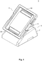
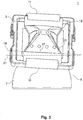
- Fig. 2 and Fig. 3 each show the mixing device 1 in a front view, wherein a container 12 is arranged in the form of a foil bag or bioreactor bag on the container carrier 3. In Fig. 3 If the positioning device 11 is shown in FIG Fig. 2 this is hidden.
- the container 12 is positioned with two opposite ends 15 by means of the positioning device 11 on the container carrier 3.
- the container 12 is fastened via flexible rods 35 (also called “rods"), which are inserted in tabs at the ends of the container 12, and the positioning device 11 in the form of clamping strips.
- the clamping bars 35 may be welded or welded into the container 12 or may be loosely inserted into plastic bottles.
- the positioning device 11 in particular in cooperation with the clamping bars 35, the position of the container 12 on the container carrier 3 is predetermined, and the removal side 17 of the container 12 is disposed along the predetermined line 19 of the container carrier 3.
- the removal pivot axis 21 is inclined relative to the predetermined line 19 or the removal side 17. From the in Fig. 2 and Fig. 3 given angle, the exact pivot axis angle is not recognizable. This would only be recognizable if the container carrier 3 would be placed perpendicular to the horizontal plane, ie perpendicular to the viewing direction in Fig. 2 and Fig. 3 would be arranged. In the exemplary embodiment, the removal pivot axis 21 horizontally aligned.
- the removal pivot axis 21 is predetermined by the pivot bearing between the container carrier 3 and the coupling element 9. If no mixing movement is carried out, the removal pivot axis 21 is fixed, in particular the removal pivot axis 21 does not move when the container carrier 3 is displaced from the mixing position into the removal position.
- Im in Fig. 2 and Figure 3 shown state is the container carrier 3 in the removal position or the intermediate layer, ie, the container 12 is in the removal position or in an intermediate position.
- the removal side 17 is inclined to the horizontal plane, in particular inclined to the removal region 23 out.
- Fig. 4 shows the mixing device 1 in a further perspective view from a different angle.
- the coupling element 9 is plate-shaped and is mounted pivotably about the tilting axis 25 on the base 7 of the movement device 5.
- the drive 27 generates a tilting movement of the coupling element 9 about the tilting axis 25 for generating the mixing movement.
- the removal pivot axis 21 is arranged.
- the removal pivot axis 21 and the tilt axis 25 are thus in the same horizontal plane.
- the removal pivot axis 21, however, is inclined about the pivot axis angle to the tilt axis 25.
- the removal pivot axis 21 is also inclined to the predetermined line, not shown, about the pivot axis angle.
- the mixing device 1 In the mixed position, the predetermined line and the tilting axis 25 are arranged parallel to each other.
- the underside of the container carrier 3 rests on the support region 31 of the coupling element 9 and is supported by it.
- the mixing device 1 has an erection mechanism 29 in the form of a gas pressure spring 29.
- the gas spring 29 is attached at one end to the coupling element 9 and at the other end to the underside of the container carrier 3.
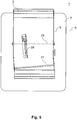
- Fig. 5 shows the mixing device 1 in a plan view.
- the removal pivot axis 21 is arranged inclined to the pivot axis 25 about the pivot axis angle.
- the gas spring 29 is oriented such that by linear method of the gas spring 29 of the container carrier 3 from the mixed position into the removal position can be relocated.
- the gas spring 29 in the initial position ie when the container carrier 3 is in the mixed position and the gas spring 29 is arranged parallel to the coupling element 9 in the horizontal plane, inclined approximately to the pivot axis angle to a line which is perpendicular to the tilt axis 25 and / or the predetermined line is.
- the gas spring-pivot axis is arranged approximately parallel to the removal pivot axis 21.
Landscapes
- Health & Medical Sciences (AREA)
- Organic Chemistry (AREA)
- Life Sciences & Earth Sciences (AREA)
- Engineering & Computer Science (AREA)
- Bioinformatics & Cheminformatics (AREA)
- Chemical & Material Sciences (AREA)
- Zoology (AREA)
- Wood Science & Technology (AREA)
- Sustainable Development (AREA)
- Microbiology (AREA)
- Biotechnology (AREA)
- Biomedical Technology (AREA)
- Biochemistry (AREA)
- General Engineering & Computer Science (AREA)
- General Health & Medical Sciences (AREA)
- Genetics & Genomics (AREA)
- Clinical Laboratory Science (AREA)
- Mixers With Rotating Receptacles And Mixers With Vibration Mechanisms (AREA)
Claims (11)
- Dispositif mélangeur (1) pour mélanger le contenu d'un récipient (12), présentant :un support de récipient (3) pour supporter le récipient (12) ; etun dispositif de déplacement (5) relié au support de récipient (3) pour déplacer le support de récipient (3) afin de pouvoir mélanger le contenu du récipient (12) dans une position de mélangeage ;sachant que le support de récipient (3) présente un dispositif de positionnement (11) qui est conçu pour positionner le récipient (12) dans une position prédéterminée ou prédéterminable sur le support de récipient (3) de manière qu'un côté de prélèvement (17) du récipient (12) soit disposé essentiellement le long d'une ligne prédéterminée (19) du support de récipient (3),sachant que le support de récipient (3) est monté de manière pivotante autour d'un axe de pivotement de prélèvement (21) par rapport au dispositif de déplacement (5) pour pouvoir déplacer le récipient (12) positionnable sur celui-ci dans une position de prélèvement,caractérisé en ce que l'axe de pivotement de prélèvement (21) est disposé d'après un angle d'axe de pivotement de plus de 0° à 45° par rapport à la ligne prédéterminée (19) du support de récipient (3) de manière que le récipient (12) positionnable sur celui-ci peut être déplacé de la position de mélange au moyen d'un mouvement de pivotement du support de récipient (3) autour de l'axe de pivotement de prélèvement (21) dans la position de prélèvement, dans laquelle le côté de prélèvement (17) est situé sur le côté inférieur du récipient (12) ainsi que incliné vers une zone de prélèvement (23) du récipient (12)
- Dispositif mélangeur (1) d'après la revendication 1, sachant que l'axe de pivotement de prélèvement (21) est disposé d'après un angle d'axe de pivotement d'environ 1° à environ 15°, de préférence d'environ 3° à environ 10°, par rapport à la ligne prédéterminée (19).
- Dispositif mélangeur (1) d'après la revendication 1 ou 2, sachant que le dispositif mobile (5) est conçu pour déplacer le support de récipient (3) en va-et-vient autour d'un axe de basculement (25) essentiellement horizontal, l'axe de basculement (25) étant disposé essentiellement de manière parallèle à la ligne prédéterminée (19).
- Dispositif mélangeur (1) d'après l'une des revendications précédentes, sachant que le dispositif de déplacement (5) présente un élément d'accouplement mobile (9) qui est raccordé au support de récipient (3) pour déplacer le support de récipient (3), sachant que le support de récipient (3) est monté de manière pivotante autour de l'axe de pivotement de prélèvement (21) sur l'élément d'accouplement (9) de manière que le support de récipient (3) puisse être déplacé d'une position de mélangeage à une position de prélèvement au moyen d'un mouvement de pivotement.
- Dispositif mélangeur (1) d'après l'une quelconque des revendications précédentes, sachant que le dispositif de positionnement (11) présente au moins un rail de serrage s'étendant essentiellement le long ou parallèlement à la ligne prédéterminée (19).
- Dispositif mélangeur (1) d'après l'une des revendications précédentes, sachant que le dispositif de positionnement (11) présente au moins un crochet de fixation disposé essentiellement le long de la ligne prédéterminée (19) ou parallèlement à celle-ci.
- Dispositif mélangeur (1) d'après l'une quelconque des revendications précédentes, sachant que le support de récipient (3) est réalisé en forme de cuve et qu'un bord intérieur du support de récipient (3) en forme de cuve s'étend essentiellement le long ou parallèlement à la ligne prédéterminée (19).
- Dispositif mélangeur d'après l'une quelconque des revendications précédentes de 4 à 7, sachant que l'élément d'accouplement (9) présente une zone d'appui (31) qui repose contre et supporte un côté inférieur du support de récipient (3) lorsque le récipient pouvant être positionné sur le support de récipient (3) est dans la position de mélangeage.
- Dispositif mélangeur (1) d'après l'une quelconque des revendications précédentes de 4 à 8, sachant que l'élément d'accouplement (9) est réalisé essentiellement en forme de plaque, sachant que l'axe de pivotement de prélèvement (21) est disposé à une extrémité de l'élément d'accouplement (9) en forme de plaque.
- Dispositif mélangeur (1) d'après l'une quelconque des revendications précédentes, comprenant en outre un mécanisme d'élévation (29) qui permet de fixer le support de récipient (3) à un angle d'élévation prédéterminé ou prédéterminable par rapport au dispositif de déplacement (5).
- Dispositif mélangeur (1) d'après la revendication 10, sachant que le mécanisme d'élévation (29) présente un levier de verrouillage disposé de manière pivotante sur le dispositif de déplacement (5) et qui soutient le support de récipient (3) lorsque le récipient (12) pouvant être positionné sur le support de récipient (3) est dans la position de prélèvement.
Priority Applications (5)
| Application Number | Priority Date | Filing Date | Title |
|---|---|---|---|
| EP14002424.1A EP2975111B1 (fr) | 2014-07-14 | 2014-07-14 | Dispositif de mélange d'un contenu d'un récipient |
| US15/325,520 US10428299B2 (en) | 2014-07-14 | 2015-05-13 | Mixing device for mixing the contents of a container |
| EP15724173.8A EP3129459A1 (fr) | 2014-07-14 | 2015-05-13 | Dispositif de mélange pour le mélange du contenu d'un récipient |
| CN201580038081.7A CN106574219B (zh) | 2014-07-14 | 2015-05-13 | 用于混合容器的内容物的混合装置 |
| PCT/EP2015/000992 WO2016008556A1 (fr) | 2014-07-14 | 2015-05-13 | Dispositif de mélange pour le mélange du contenu d'un récipient |
Applications Claiming Priority (1)
| Application Number | Priority Date | Filing Date | Title |
|---|---|---|---|
| EP14002424.1A EP2975111B1 (fr) | 2014-07-14 | 2014-07-14 | Dispositif de mélange d'un contenu d'un récipient |
Publications (2)
| Publication Number | Publication Date |
|---|---|
| EP2975111A1 EP2975111A1 (fr) | 2016-01-20 |
| EP2975111B1 true EP2975111B1 (fr) | 2018-05-16 |
Family
ID=51211482
Family Applications (2)
| Application Number | Title | Priority Date | Filing Date |
|---|---|---|---|
| EP14002424.1A Active EP2975111B1 (fr) | 2014-07-14 | 2014-07-14 | Dispositif de mélange d'un contenu d'un récipient |
| EP15724173.8A Withdrawn EP3129459A1 (fr) | 2014-07-14 | 2015-05-13 | Dispositif de mélange pour le mélange du contenu d'un récipient |
Family Applications After (1)
| Application Number | Title | Priority Date | Filing Date |
|---|---|---|---|
| EP15724173.8A Withdrawn EP3129459A1 (fr) | 2014-07-14 | 2015-05-13 | Dispositif de mélange pour le mélange du contenu d'un récipient |
Country Status (4)
| Country | Link |
|---|---|
| US (1) | US10428299B2 (fr) |
| EP (2) | EP2975111B1 (fr) |
| CN (1) | CN106574219B (fr) |
| WO (1) | WO2016008556A1 (fr) |
Cited By (2)
| Publication number | Priority date | Publication date | Assignee | Title |
|---|---|---|---|---|
| EP3620506A1 (fr) | 2018-09-05 | 2020-03-11 | Sartorius Stedim Switzerland AG | Dispositif de récolte et procédé pour récolter le contenu d'un sac de bioréacteur |
| WO2020099342A3 (fr) * | 2018-11-13 | 2020-07-23 | Global Life Sciences Solutions Usa Llc | Appareil, système et procédé de biotraitement |
Families Citing this family (1)
| Publication number | Priority date | Publication date | Assignee | Title |
|---|---|---|---|---|
| US10617070B2 (en) * | 2014-10-06 | 2020-04-14 | Life Technologies Corporation | Methods and systems for culturing microbial and cellular seed cultures |
Family Cites Families (6)
| Publication number | Priority date | Publication date | Assignee | Title |
|---|---|---|---|---|
| FR2667393B1 (fr) * | 1990-10-01 | 1994-12-23 | Alain Fillaud | Dispositif de pesee et d'agitation simultanee. |
| US6190913B1 (en) * | 1997-08-12 | 2001-02-20 | Vijay Singh | Method for culturing cells using wave-induced agitation |
| CH697035A5 (de) * | 1999-05-04 | 2008-03-31 | Marcel Roell | Bioreaktor. |
| BE1016538A3 (fr) * | 2004-02-20 | 2007-01-09 | Cesco Bioengineering Co Ltd | Appareil et procede pour la preparation et la mise en culture de cellules. |
| CN103391996A (zh) * | 2011-02-23 | 2013-11-13 | 通用电气健康护理生物科学股份公司 | 包括摇动装置的生物反应器 |
| EP2639294A1 (fr) * | 2012-03-15 | 2013-09-18 | CellProthera | Automate et procédé automatisé de culture cellulaire |
-
2014
- 2014-07-14 EP EP14002424.1A patent/EP2975111B1/fr active Active
-
2015
- 2015-05-13 US US15/325,520 patent/US10428299B2/en active Active
- 2015-05-13 EP EP15724173.8A patent/EP3129459A1/fr not_active Withdrawn
- 2015-05-13 CN CN201580038081.7A patent/CN106574219B/zh active Active
- 2015-05-13 WO PCT/EP2015/000992 patent/WO2016008556A1/fr active Application Filing
Non-Patent Citations (1)
| Title |
|---|
| None * |
Cited By (2)
| Publication number | Priority date | Publication date | Assignee | Title |
|---|---|---|---|---|
| EP3620506A1 (fr) | 2018-09-05 | 2020-03-11 | Sartorius Stedim Switzerland AG | Dispositif de récolte et procédé pour récolter le contenu d'un sac de bioréacteur |
| WO2020099342A3 (fr) * | 2018-11-13 | 2020-07-23 | Global Life Sciences Solutions Usa Llc | Appareil, système et procédé de biotraitement |
Also Published As
| Publication number | Publication date |
|---|---|
| US20170159001A1 (en) | 2017-06-08 |
| WO2016008556A1 (fr) | 2016-01-21 |
| EP3129459A1 (fr) | 2017-02-15 |
| EP2975111A1 (fr) | 2016-01-20 |
| US10428299B2 (en) | 2019-10-01 |
| CN106574219B (zh) | 2018-12-04 |
| CN106574219A (zh) | 2017-04-19 |
Similar Documents
| Publication | Publication Date | Title |
|---|---|---|
| DE102006062714B4 (de) | Vorrichtung zum Mischen von Laborgefäß-Inhalten | |
| EP2205716B1 (fr) | Microréacteur | |
| EP1715312B1 (fr) | Balance pourvue d'une protection contre le vent | |
| DE60211760T2 (de) | Vorrichtung und Verfahren zum parallelen Verarbeiten einer Vielzahl von Reaktionsgemischen | |
| EP1110609B1 (fr) | Système de traitement d'échantillons dans un dispositif à compartiments multiples | |
| EP2015863B1 (fr) | Système de récipients avec un récipient doté d'une paroi flexible | |
| EP2117691B1 (fr) | Dispositif multiposte pour mélanger des contenus de récipients de laboratoire | |
| EP2975111B1 (fr) | Dispositif de mélange d'un contenu d'un récipient | |
| EP2388561A1 (fr) | Appareil de laboratoire pour la préparation d'échantillons | |
| EP2669000B1 (fr) | Dispositif de mélange doté d'un palier pour un dispositif de réception, procédé de mélange associé, et l'utilisation d'un tel dispositif de mélange | |
| DE102014004851B4 (de) | Vertikales funktionelles Reaktionsgefäß | |
| WO2008000312A1 (fr) | Plaque de microtitration comprenant des éléments d'agitation | |
| EP1499899A1 (fr) | Station de traitement d'echantillons | |
| EP2259032A1 (fr) | Dispositif de protection contre le vent pour un appareil de laboratoire | |
| EP3479894B1 (fr) | Secoueur | |
| EP3227011B1 (fr) | Dispositif de mélange avec brise-flux | |
| EP3080614B1 (fr) | Dispositif de manipulation d'échantillons | |
| DE102021002036A1 (de) | Schüttelplattform mit anpassbarer haltevorrichtung zur behälterbefestigung, haltevorrichtung und laborschütteleinrichtung | |
| EP4059592A1 (fr) | Éprouvette, ainsi que dispositif et procédé de dispersion et d'homogénéisation | |
| EP4218996B1 (fr) | Appareil mélangeur, système mélangeur et procédé pour mélanger des substances dans conteneurs fermés | |
| DE102021200359B4 (de) | Halteklemme zum halten einer eckigen flasche auf einer schüttelplattform einer laborschütteleinrichtung | |
| DE3706002A1 (de) | Vorrichtung zum zerkleinern, mischen, kneten und schlagen von gut | |
| EP3927454A1 (fr) | Procédé et dispositif pour mettre en ?uvre des processus de réaction | |
| LU100170B1 (de) | Verfahren zum Prozessieren einer flüssigen Probe | |
| WO1998057740A1 (fr) | Dispositif pour temperer des gaz, des liquides et/ou des solides dans une eprouvette |
Legal Events
| Date | Code | Title | Description |
|---|---|---|---|
| PUAI | Public reference made under article 153(3) epc to a published international application that has entered the european phase |
Free format text: ORIGINAL CODE: 0009012 |
|
| AK | Designated contracting states |
Kind code of ref document: A1 Designated state(s): AL AT BE BG CH CY CZ DE DK EE ES FI FR GB GR HR HU IE IS IT LI LT LU LV MC MK MT NL NO PL PT RO RS SE SI SK SM TR |
|
| AX | Request for extension of the european patent |
Extension state: BA ME |
|
| 17P | Request for examination filed |
Effective date: 20160204 |
|
| RBV | Designated contracting states (corrected) |
Designated state(s): AL AT BE BG CH CY CZ DE DK EE ES FI FR GB GR HR HU IE IS IT LI LT LU LV MC MK MT NL NO PL PT RO RS SE SI SK SM TR |
|
| GRAP | Despatch of communication of intention to grant a patent |
Free format text: ORIGINAL CODE: EPIDOSNIGR1 |
|
| INTG | Intention to grant announced |
Effective date: 20171207 |
|
| GRAS | Grant fee paid |
Free format text: ORIGINAL CODE: EPIDOSNIGR3 |
|
| GRAA | (expected) grant |
Free format text: ORIGINAL CODE: 0009210 |
|
| AK | Designated contracting states |
Kind code of ref document: B1 Designated state(s): AL AT BE BG CH CY CZ DE DK EE ES FI FR GB GR HR HU IE IS IT LI LT LU LV MC MK MT NL NO PL PT RO RS SE SI SK SM TR |
|
| REG | Reference to a national code |
Ref country code: GB Ref legal event code: FG4D Free format text: NOT ENGLISH |
|
| REG | Reference to a national code |
Ref country code: CH Ref legal event code: EP |
|
| REG | Reference to a national code |
Ref country code: FR Ref legal event code: PLFP Year of fee payment: 5 |
|
| REG | Reference to a national code |
Ref country code: IE Ref legal event code: FG4D Free format text: LANGUAGE OF EP DOCUMENT: GERMAN |
|
| REG | Reference to a national code |
Ref country code: DE Ref legal event code: R096 Ref document number: 502014008249 Country of ref document: DE |
|
| REG | Reference to a national code |
Ref country code: AT Ref legal event code: REF Ref document number: 999579 Country of ref document: AT Kind code of ref document: T Effective date: 20180615 |
|
| REG | Reference to a national code |
Ref country code: NL Ref legal event code: MP Effective date: 20180516 |
|
| REG | Reference to a national code |
Ref country code: LT Ref legal event code: MG4D |
|
| PG25 | Lapsed in a contracting state [announced via postgrant information from national office to epo] |
Ref country code: BG Free format text: LAPSE BECAUSE OF FAILURE TO SUBMIT A TRANSLATION OF THE DESCRIPTION OR TO PAY THE FEE WITHIN THE PRESCRIBED TIME-LIMIT Effective date: 20180816 Ref country code: FI Free format text: LAPSE BECAUSE OF FAILURE TO SUBMIT A TRANSLATION OF THE DESCRIPTION OR TO PAY THE FEE WITHIN THE PRESCRIBED TIME-LIMIT Effective date: 20180516 Ref country code: LT Free format text: LAPSE BECAUSE OF FAILURE TO SUBMIT A TRANSLATION OF THE DESCRIPTION OR TO PAY THE FEE WITHIN THE PRESCRIBED TIME-LIMIT Effective date: 20180516 Ref country code: NO Free format text: LAPSE BECAUSE OF FAILURE TO SUBMIT A TRANSLATION OF THE DESCRIPTION OR TO PAY THE FEE WITHIN THE PRESCRIBED TIME-LIMIT Effective date: 20180816 Ref country code: SE Free format text: LAPSE BECAUSE OF FAILURE TO SUBMIT A TRANSLATION OF THE DESCRIPTION OR TO PAY THE FEE WITHIN THE PRESCRIBED TIME-LIMIT Effective date: 20180516 Ref country code: ES Free format text: LAPSE BECAUSE OF FAILURE TO SUBMIT A TRANSLATION OF THE DESCRIPTION OR TO PAY THE FEE WITHIN THE PRESCRIBED TIME-LIMIT Effective date: 20180516 |
|
| PG25 | Lapsed in a contracting state [announced via postgrant information from national office to epo] |
Ref country code: LV Free format text: LAPSE BECAUSE OF FAILURE TO SUBMIT A TRANSLATION OF THE DESCRIPTION OR TO PAY THE FEE WITHIN THE PRESCRIBED TIME-LIMIT Effective date: 20180516 Ref country code: NL Free format text: LAPSE BECAUSE OF FAILURE TO SUBMIT A TRANSLATION OF THE DESCRIPTION OR TO PAY THE FEE WITHIN THE PRESCRIBED TIME-LIMIT Effective date: 20180516 Ref country code: RS Free format text: LAPSE BECAUSE OF FAILURE TO SUBMIT A TRANSLATION OF THE DESCRIPTION OR TO PAY THE FEE WITHIN THE PRESCRIBED TIME-LIMIT Effective date: 20180516 Ref country code: HR Free format text: LAPSE BECAUSE OF FAILURE TO SUBMIT A TRANSLATION OF THE DESCRIPTION OR TO PAY THE FEE WITHIN THE PRESCRIBED TIME-LIMIT Effective date: 20180516 Ref country code: GR Free format text: LAPSE BECAUSE OF FAILURE TO SUBMIT A TRANSLATION OF THE DESCRIPTION OR TO PAY THE FEE WITHIN THE PRESCRIBED TIME-LIMIT Effective date: 20180817 |
|
| PG25 | Lapsed in a contracting state [announced via postgrant information from national office to epo] |
Ref country code: PL Free format text: LAPSE BECAUSE OF FAILURE TO SUBMIT A TRANSLATION OF THE DESCRIPTION OR TO PAY THE FEE WITHIN THE PRESCRIBED TIME-LIMIT Effective date: 20180516 Ref country code: EE Free format text: LAPSE BECAUSE OF FAILURE TO SUBMIT A TRANSLATION OF THE DESCRIPTION OR TO PAY THE FEE WITHIN THE PRESCRIBED TIME-LIMIT Effective date: 20180516 Ref country code: SK Free format text: LAPSE BECAUSE OF FAILURE TO SUBMIT A TRANSLATION OF THE DESCRIPTION OR TO PAY THE FEE WITHIN THE PRESCRIBED TIME-LIMIT Effective date: 20180516 Ref country code: DK Free format text: LAPSE BECAUSE OF FAILURE TO SUBMIT A TRANSLATION OF THE DESCRIPTION OR TO PAY THE FEE WITHIN THE PRESCRIBED TIME-LIMIT Effective date: 20180516 Ref country code: RO Free format text: LAPSE BECAUSE OF FAILURE TO SUBMIT A TRANSLATION OF THE DESCRIPTION OR TO PAY THE FEE WITHIN THE PRESCRIBED TIME-LIMIT Effective date: 20180516 Ref country code: CZ Free format text: LAPSE BECAUSE OF FAILURE TO SUBMIT A TRANSLATION OF THE DESCRIPTION OR TO PAY THE FEE WITHIN THE PRESCRIBED TIME-LIMIT Effective date: 20180516 |
|
| REG | Reference to a national code |
Ref country code: DE Ref legal event code: R097 Ref document number: 502014008249 Country of ref document: DE |
|
| PG25 | Lapsed in a contracting state [announced via postgrant information from national office to epo] |
Ref country code: SM Free format text: LAPSE BECAUSE OF FAILURE TO SUBMIT A TRANSLATION OF THE DESCRIPTION OR TO PAY THE FEE WITHIN THE PRESCRIBED TIME-LIMIT Effective date: 20180516 Ref country code: IT Free format text: LAPSE BECAUSE OF FAILURE TO SUBMIT A TRANSLATION OF THE DESCRIPTION OR TO PAY THE FEE WITHIN THE PRESCRIBED TIME-LIMIT Effective date: 20180516 |
|
| REG | Reference to a national code |
Ref country code: CH Ref legal event code: PL |
|
| PLBE | No opposition filed within time limit |
Free format text: ORIGINAL CODE: 0009261 |
|
| STAA | Information on the status of an ep patent application or granted ep patent |
Free format text: STATUS: NO OPPOSITION FILED WITHIN TIME LIMIT |
|
| PG25 | Lapsed in a contracting state [announced via postgrant information from national office to epo] |
Ref country code: LU Free format text: LAPSE BECAUSE OF NON-PAYMENT OF DUE FEES Effective date: 20180714 Ref country code: MC Free format text: LAPSE BECAUSE OF FAILURE TO SUBMIT A TRANSLATION OF THE DESCRIPTION OR TO PAY THE FEE WITHIN THE PRESCRIBED TIME-LIMIT Effective date: 20180516 |
|
| REG | Reference to a national code |
Ref country code: BE Ref legal event code: MM Effective date: 20180731 |
|
| REG | Reference to a national code |
Ref country code: IE Ref legal event code: MM4A |
|
| 26N | No opposition filed |
Effective date: 20190219 |
|
| PG25 | Lapsed in a contracting state [announced via postgrant information from national office to epo] |
Ref country code: CH Free format text: LAPSE BECAUSE OF NON-PAYMENT OF DUE FEES Effective date: 20180731 Ref country code: LI Free format text: LAPSE BECAUSE OF NON-PAYMENT OF DUE FEES Effective date: 20180731 Ref country code: IE Free format text: LAPSE BECAUSE OF NON-PAYMENT OF DUE FEES Effective date: 20180714 |
|
| PG25 | Lapsed in a contracting state [announced via postgrant information from national office to epo] |
Ref country code: BE Free format text: LAPSE BECAUSE OF NON-PAYMENT OF DUE FEES Effective date: 20180731 Ref country code: SI Free format text: LAPSE BECAUSE OF FAILURE TO SUBMIT A TRANSLATION OF THE DESCRIPTION OR TO PAY THE FEE WITHIN THE PRESCRIBED TIME-LIMIT Effective date: 20180516 |
|
| PG25 | Lapsed in a contracting state [announced via postgrant information from national office to epo] |
Ref country code: AL Free format text: LAPSE BECAUSE OF FAILURE TO SUBMIT A TRANSLATION OF THE DESCRIPTION OR TO PAY THE FEE WITHIN THE PRESCRIBED TIME-LIMIT Effective date: 20180516 |
|
| PG25 | Lapsed in a contracting state [announced via postgrant information from national office to epo] |
Ref country code: MT Free format text: LAPSE BECAUSE OF FAILURE TO SUBMIT A TRANSLATION OF THE DESCRIPTION OR TO PAY THE FEE WITHIN THE PRESCRIBED TIME-LIMIT Effective date: 20180516 |
|
| PG25 | Lapsed in a contracting state [announced via postgrant information from national office to epo] |
Ref country code: TR Free format text: LAPSE BECAUSE OF FAILURE TO SUBMIT A TRANSLATION OF THE DESCRIPTION OR TO PAY THE FEE WITHIN THE PRESCRIBED TIME-LIMIT Effective date: 20180516 |
|
| PG25 | Lapsed in a contracting state [announced via postgrant information from national office to epo] |
Ref country code: PT Free format text: LAPSE BECAUSE OF FAILURE TO SUBMIT A TRANSLATION OF THE DESCRIPTION OR TO PAY THE FEE WITHIN THE PRESCRIBED TIME-LIMIT Effective date: 20180516 |
|
| PG25 | Lapsed in a contracting state [announced via postgrant information from national office to epo] |
Ref country code: HU Free format text: LAPSE BECAUSE OF FAILURE TO SUBMIT A TRANSLATION OF THE DESCRIPTION OR TO PAY THE FEE WITHIN THE PRESCRIBED TIME-LIMIT; INVALID AB INITIO Effective date: 20140714 Ref country code: CY Free format text: LAPSE BECAUSE OF FAILURE TO SUBMIT A TRANSLATION OF THE DESCRIPTION OR TO PAY THE FEE WITHIN THE PRESCRIBED TIME-LIMIT Effective date: 20180516 Ref country code: MK Free format text: LAPSE BECAUSE OF NON-PAYMENT OF DUE FEES Effective date: 20180516 |
|
| PG25 | Lapsed in a contracting state [announced via postgrant information from national office to epo] |
Ref country code: IS Free format text: LAPSE BECAUSE OF FAILURE TO SUBMIT A TRANSLATION OF THE DESCRIPTION OR TO PAY THE FEE WITHIN THE PRESCRIBED TIME-LIMIT Effective date: 20180916 |
|
| REG | Reference to a national code |
Ref country code: AT Ref legal event code: MM01 Ref document number: 999579 Country of ref document: AT Kind code of ref document: T Effective date: 20190714 |
|
| PG25 | Lapsed in a contracting state [announced via postgrant information from national office to epo] |
Ref country code: AT Free format text: LAPSE BECAUSE OF NON-PAYMENT OF DUE FEES Effective date: 20190714 |
|
| P01 | Opt-out of the competence of the unified patent court (upc) registered |
Effective date: 20230508 |
|
| PGFP | Annual fee paid to national office [announced via postgrant information from national office to epo] |
Ref country code: GB Payment date: 20230724 Year of fee payment: 10 |
|
| PGFP | Annual fee paid to national office [announced via postgrant information from national office to epo] |
Ref country code: FR Payment date: 20230724 Year of fee payment: 10 Ref country code: DE Payment date: 20230720 Year of fee payment: 10 |