EP2975111B1 - Mixing device for mixing a content of a container - Google Patents
Mixing device for mixing a content of a container Download PDFInfo
- Publication number
- EP2975111B1 EP2975111B1 EP14002424.1A EP14002424A EP2975111B1 EP 2975111 B1 EP2975111 B1 EP 2975111B1 EP 14002424 A EP14002424 A EP 14002424A EP 2975111 B1 EP2975111 B1 EP 2975111B1
- Authority
- EP
- European Patent Office
- Prior art keywords
- container
- removal
- mixing
- pivot axis
- container support
- Prior art date
- Legal status (The legal status is an assumption and is not a legal conclusion. Google has not performed a legal analysis and makes no representation as to the accuracy of the status listed.)
- Active
Links
- 238000002156 mixing Methods 0.000 title claims description 74
- 230000008878 coupling Effects 0.000 claims description 39
- 238000010168 coupling process Methods 0.000 claims description 39
- 238000005859 coupling reaction Methods 0.000 claims description 39
- 230000007246 mechanism Effects 0.000 claims description 10
- 239000007789 gas Substances 0.000 description 10
- 238000000605 extraction Methods 0.000 description 9
- 239000000969 carrier Substances 0.000 description 4
- 239000012530 fluid Substances 0.000 description 3
- 239000011888 foil Substances 0.000 description 3
- 239000007788 liquid Substances 0.000 description 3
- 238000000034 method Methods 0.000 description 3
- 239000000725 suspension Substances 0.000 description 3
- QVGXLLKOCUKJST-UHFFFAOYSA-N atomic oxygen Chemical compound [O] QVGXLLKOCUKJST-UHFFFAOYSA-N 0.000 description 2
- 238000004113 cell culture Methods 0.000 description 2
- 238000010276 construction Methods 0.000 description 2
- 238000011109 contamination Methods 0.000 description 2
- 238000006073 displacement reaction Methods 0.000 description 2
- 238000004519 manufacturing process Methods 0.000 description 2
- 239000000463 material Substances 0.000 description 2
- 239000002207 metabolite Substances 0.000 description 2
- 244000005700 microbiome Species 0.000 description 2
- 239000001301 oxygen Substances 0.000 description 2
- 229910052760 oxygen Inorganic materials 0.000 description 2
- 230000008569 process Effects 0.000 description 2
- 239000000126 substance Substances 0.000 description 2
- 238000010364 biochemical engineering Methods 0.000 description 1
- 238000011138 biotechnological process Methods 0.000 description 1
- 238000004140 cleaning Methods 0.000 description 1
- 230000001419 dependent effect Effects 0.000 description 1
- 230000008030 elimination Effects 0.000 description 1
- 238000003379 elimination reaction Methods 0.000 description 1
- 238000005516 engineering process Methods 0.000 description 1
- 239000011521 glass Substances 0.000 description 1
- 230000005484 gravity Effects 0.000 description 1
- 239000001963 growth medium Substances 0.000 description 1
- 230000036512 infertility Effects 0.000 description 1
- 238000009434 installation Methods 0.000 description 1
- 230000002503 metabolic effect Effects 0.000 description 1
- 239000000203 mixture Substances 0.000 description 1
- 235000015097 nutrients Nutrition 0.000 description 1
- 238000004062 sedimentation Methods 0.000 description 1
- 238000003892 spreading Methods 0.000 description 1
- 230000007480 spreading Effects 0.000 description 1
- 229910001220 stainless steel Inorganic materials 0.000 description 1
- 239000010935 stainless steel Substances 0.000 description 1
- 238000003756 stirring Methods 0.000 description 1
- 238000003860 storage Methods 0.000 description 1
- 239000013598 vector Substances 0.000 description 1
Images


Classifications
-
- C—CHEMISTRY; METALLURGY
- C12—BIOCHEMISTRY; BEER; SPIRITS; WINE; VINEGAR; MICROBIOLOGY; ENZYMOLOGY; MUTATION OR GENETIC ENGINEERING
- C12M—APPARATUS FOR ENZYMOLOGY OR MICROBIOLOGY; APPARATUS FOR CULTURING MICROORGANISMS FOR PRODUCING BIOMASS, FOR GROWING CELLS OR FOR OBTAINING FERMENTATION OR METABOLIC PRODUCTS, i.e. BIOREACTORS OR FERMENTERS
- C12M23/00—Constructional details, e.g. recesses, hinges
- C12M23/02—Form or structure of the vessel
- C12M23/14—Bags
-
- C—CHEMISTRY; METALLURGY
- C12—BIOCHEMISTRY; BEER; SPIRITS; WINE; VINEGAR; MICROBIOLOGY; ENZYMOLOGY; MUTATION OR GENETIC ENGINEERING
- C12M—APPARATUS FOR ENZYMOLOGY OR MICROBIOLOGY; APPARATUS FOR CULTURING MICROORGANISMS FOR PRODUCING BIOMASS, FOR GROWING CELLS OR FOR OBTAINING FERMENTATION OR METABOLIC PRODUCTS, i.e. BIOREACTORS OR FERMENTERS
- C12M27/00—Means for mixing, agitating or circulating fluids in the vessel
- C12M27/16—Vibrating; Shaking; Tilting
-
- C—CHEMISTRY; METALLURGY
- C12—BIOCHEMISTRY; BEER; SPIRITS; WINE; VINEGAR; MICROBIOLOGY; ENZYMOLOGY; MUTATION OR GENETIC ENGINEERING
- C12M—APPARATUS FOR ENZYMOLOGY OR MICROBIOLOGY; APPARATUS FOR CULTURING MICROORGANISMS FOR PRODUCING BIOMASS, FOR GROWING CELLS OR FOR OBTAINING FERMENTATION OR METABOLIC PRODUCTS, i.e. BIOREACTORS OR FERMENTERS
- C12M23/00—Constructional details, e.g. recesses, hinges
- C12M23/46—Means for fastening
Definitions
- the present invention relates to a mixing device for mixing a content of a container.
- containers are used for mixing or circulating materials.
- culture media for microorganisms or controlled biotechnological processes such as cell cultivation of the mixing or the circulation of the container contents is of particular importance. Due to the different initial concentrations of the substances and the metabolic activity of the microorganisms during cultivation, there are local concentration changes of various chemical components in the media mixture or of nutrients, oxygen and the resulting metabolites during cultivation. In order to ensure the same or at least controlled concentration conditions in the entire container, it is necessary to mix or circulate the liquid or suspension in the container during the entire process.
- stirrerless mixers are known as rockers, platform shakers, tumble mixers, orbital shakers, vibratory shakers, horizontal shakers, orbital shakers, etc.
- Flexible containers may vary in size depending on the application, with larger containers having volumes of several liters.
- the most previously filled containers are usually placed on plate-shaped or trough-shaped movable supports, e.g. be fixed by clamps or hooks or other releasable fasteners on the carriers.
- the carriers are driven and produce the mixing movement of the contents of the container.
- the carrier carries out, for example, a rocking movement about a horizontal position.
- the carriers In order to remove the contents of the bag, the carriers can be moved with the bags fixed thereon in a nearly vertical position. It may also be possible to fill the containers in the vertical position.
- WO 2012/115581 A1 discloses a bioreactor with a mixing device in which a container carrier performs a rocking motion about a horizontal rocking axis for mixing a content of a container.
- a container carrier performs a rocking motion about a horizontal rocking axis for mixing a content of a container.
- an erection axis is arranged, about which the container carrier can be pivoted for setting up the container carrier, wherein the erecting axis is parallel to the rocking axis.
- the container carrier can be inclined in the erected state about a second tilting axis, which is perpendicular to the erection axis, to a corner of the container.
- US 2013/0244322 A1 discloses a bioreactor with a mixing device in which a container carrier performs a rocking motion about a horizontal rocking axis for mixing a content of a container.
- a horizontal erecting axis is arranged, about which the container carrier can be pivoted for setting up the container carrier, wherein the erecting axis is parallel to the rocking axis.
- a mixing apparatus for mixing a contents of a container, comprising: a container carrier for carrying the container; and a moving device connected to move the container carrier with the container carrier to mix the contents of the container in a mixing position; the container carrier having a positioning device adapted to position the container in a predetermined position on the container carrier such that a withdrawal side of the container is disposed substantially along a predetermined line of the container carrier the container carrier is pivotally mounted about a take-off pivot axis relative to the moving device to move the positionable container into a removal position, wherein the removal pivot axis in such a pivot axis angle of about 0 ° to 45 ° to the predetermined line of the container Carrier is arranged so that the positionable container can be moved from the mixing position by means of a pivoting movement of the container carrier to the removal pivot axis in the removal position in which the removal side located on the lower side of the container and to a Removal of the container is inclined.
- the container may, in particular, be a bioreactor container, which may be made of a film material. Such a container can be welded as a bag with at least two opposite sides Be executed edges.
- the container may have a predetermined bearing surface on which the container can be stored stably on a horizontal surface.
- the support surface may in particular be one of its largest surfaces or side surfaces.
- the support surface and / or the surface opposite the support surface may have passages and connections for supply and / or discharge lines and / or sensors. If the supply and / or discharge lines are located on the support surface, the container carrier also has corresponding passages for the connected lines.
- the container can be arranged with its bearing surface on the container carrier.
- the container may have in plan view a substantially quadrangular shape with four side edges.
- the container may be formed symmetrically in plan view, which is advantageous for a uniform movement of the contents of the container during mixing.
- At least the container has a removal side.
- the removal side may be a substantially straight side edge of the container, wherein a side edge of the container interior is meant.
- the withdrawal side refers to the side of the container which is provided for collection and removal of the contents of the container and in particular of the products which have formed in the container.
- the removal area of the container can be arranged in one of the two corners of the removal side. At the removal area, an outlet can be arranged, from which the contents of the container can be omitted.
- the container positioned on the container carrier is displaced together with the container carrier for removal into the removal position.
- a filling of the container is also possible in this position via the supply lines arranged on the container.
- the contents of the container may be a liquid or a suspension.
- the container may further contain a gas or gases.
- the content of the container is mixed or circulated by means of the mixing device, whereby a good oxygen mixing can be ensured in particular during cell cultivation.
- the container carrier is designed such that the container is arranged thereon can be.
- the container carrier may be formed such that the container with its container carrier facing the largest surface or its support surface substantially completely rests against the upper surface of the container carrier.
- the upper surface of the container carrier may be referred to as a receiving surface.
- the container carrier may for example be formed plate-shaped or trough-shaped and executed in the plan view is substantially square. Essentially, the trough-shaped container carriers serve to absorb the escaping fluid from the containers in the event of leaks in the containers. However, there are also trough-shaped container carrier with one or more open corners or openings possible over which the discharge lines are guided in the installation position so as to facilitate removal from the container.
- the size of the container carrier is not limited and may be selected depending on the container size.
- the shape and size of the container carrier in the plan view corresponds substantially to the shape and size of the container in plan view.
- the moving device is configured to move the container carrier to perform the mixing movement.
- the movement device preferably via a movable coupling element, connected to the container carrier.
- the container carrier When moving the container to mix the contents of the container, the container carrier is in a mixing position and the container positioned thereon is in a mixing position. In the mixed position, the container carrier, or the receiving surface thereof, is oriented substantially horizontally. More specifically, in the mixing layer for mixing, the container carrier performs motion around or in the horizontal plane.
- the mixing device may be referred to as rocker, platform shaker, tumble mixer, orbital shaker, vibratory shaker, horizontal shaker, orbital shaker, etc.
- the container carrier performs a tilting or rocking motion about a substantially horizontal axis, with the container carrier initially in a range of about 0-15 °, preferably in a range of about 0-10 °, is inclined to the horizontal plane, and then in the opposite direction in a range of about 0-15 °, preferably in a range of about 0-10 °, is inclined to the horizontal plane.
- This movement of the container carrier is transmitted to the container, so that a wave motion of the Contents of the container can be generated.
- the mixing movement of the container support does not necessarily include inclining to the horizontal plane, and instead the container support may be reciprocated linearly or circularly in the horizontal plane and / or horizontally reciprocated in the vertical direction be shaken.
- the mixed layer is thus changeable by the movement of the container carrier, but is substantially in the horizontal plane or differs only slightly from this.
- the container carrier has a predetermined or predeterminable rest position, which is assumed when the container carrier performs no mixing movement in the mixing position.
- the container disposed on the container carrier In the rest position, the container disposed on the container carrier is in a rest position. In the rest position or rest position, the container carrier or the container is preferably oriented approximately horizontally. The same applies to the mixing position of the arranged on the container carrier container.
- the container carrier has a positioning device, which can be provided in each case on one or more sides of the container carrier.
- the positioning device may have, for example, terminals, clamping rails and / or fastening hooks.
- the positioning device can enable releasable positioning or fixing of the container to the container carrier.
- the positioning device is adapted to position the container in a predetermined position on the container carrier such that the withdrawal side of the container is disposed substantially along a predetermined imaginary line of the container carrier.
- the predetermined line is an imaginary line and does not need to be visible on the container carrier.
- This imaginary line of the container carrier extends the removal side of the container, in particular the substantially straight side edge of the container interior, when the container is positioned by means of the positioning device on the container carrier.
- the predetermined line may be connected to a side edge of the container carrier on the Matching page, or parallel to this.
- the removal pivot axis can also be defined in this case with respect to the side edge of the container carrier, namely that the removal pivot axis at an angle of about 0 ° to 45 °, preferably about 1 ° to about 15 °, more preferably about 3 ° to about 10 °, is arranged to the side edge of the container carrier.
- the predetermined line can also coincide with the extension direction of a clamping rail of the positioning device or run parallel to it.
- the removal pivot axis can also be defined in this case with respect to the extension direction of the clamping rail, namely that the removal pivot axis at an angle of about 0 ° to 45 °, preferably about 1 ° to about 15 °, more preferably about 3 ° is arranged to about 10 °, to the extension direction of the clamping rail.
- the container carrier may have a stop for the removal side of the container, in which case the predetermined line may coincide with the direction of extension of the stop or may be parallel thereto.
- the removal pivot axis can also be defined in this case with respect to the extension direction of the stop, namely that the removal pivot axis at an angle of about 0 ° to 45 °, preferably about 1 ° to about 15 °, more preferably about 3 ° is arranged to about 10 °, to the extension direction of the stop.
- the predetermined line may be parallel to an axis of symmetry of the container carrier.
- the removal pivot axis can also be defined in this case with respect to the symmetry axis of the container carrier, namely that the removal pivot axis at an angle of about 0 ° to 45 °, preferably about 1 ° to about 15 °, more preferably about 3 ° to about 10 °, is arranged to the axis of symmetry of the container carrier.
- the container carrier is pivotally mounted on the moving device and can be pivoted relative to the moving device. This pivoting movement is independent of the mixing movement of the container carrier and is basically not carried out during the mixing movement.
- the pivotability of the container carrier relative to the movement device allows a displacement of the container carrier from the mixing layer into a removal position. Accordingly, the pivotability of the container carrier relative to the movement device allows a displacement of the arranged on the container carrier container from a mixing position to a removal position.
- the shifting from the mixing position or mixing position into the removal position or removal position can also be referred to as "erection".
- the container In the removal position, the container is oriented such that the removal side is located in the vertical direction on the lower side of the container and is inclined to a removal region of the container.
- the removal region may be located in the region of one of the lower corners of the container, wherein the removal region may be located directly in the corner itself or on the upper surface or support surface of the container near the corner.
- the support surface of the container In the removal position, the support surface of the container is inclined at a steep angle to the horizontal plane, and the withdrawal side of the container forms the lower side or edge of the container.
- the withdrawal side of the container is inclined to the horizontal plane, but at a shallower angle.
- the inclination angle of the extraction side to the horizontal plane approximately corresponds to the pivot axis angle between the extraction pivot axis and the predetermined line of the container support.
- the support surface is inclined less than 90 ° to the horizontal plane, the inclination angle of the extraction side to the horizontal plane is less than the pivot axis angle between the extraction pivot axis and the predetermined line of the container support.
- the support surface of the container may be inclined in the removal position at an angle of 30 ° to 90 °, preferably 35 ° to 55 ° to the horizontal plane.
- the receiving surface of the container carrier in the picking position, is inclined at a steep angle to the horizontal plane, and the predetermined line of the container carrier is also to the horizontal plane inclined, but at a shallower angle.
- the inclination angle of the predetermined line to the horizontal plane approximately corresponds to the pivot axis angle between the take-off pivot axis and the predetermined line.
- the inclination angle of the predetermined line to the horizontal plane is less than the pivot axis angle between the unloading pivot axis and the predetermined line.
- the receiving surface of the container carrier may be inclined in the removal position at an angle of 30 ° to 90 °, preferably 35 ° to 55 ° to the horizontal plane.
- the container support (or the receiving surface thereof) is oriented substantially to the horizontal plane, the above explanations regarding the inclinations in relation to the horizontal plane essentially also apply to the inclinations in Relation to the mixed position or rest position.
- the take-off pivot axis is located at a pivot axis angle greater than 0 ° to 45 ° to the predetermined line of the container support, here the smallest angle (ie, an angle between 0 ° and 90 °) between the take-off pivot axis and the predetermined line is. If the extraction pivot axis and the predetermined line do not intersect in space, that is skew, the pivot axis angle is to be determined as the angle between the direction vectors of the extraction pivot axis and the predetermined line. In other words, the pivot axis angle is the largest detectable angle between 0 ° and 90 ° between the projected lines of the extraction pivot axis and the predetermined line on all possible planes in space.
- the pivot axis angle corresponds to the angle between the lines projected on the horizontal plane of the extraction pivot axis and the predetermined line when the container support (or the receiving surface thereof) is aligned to the horizontal plane or if the container carrier in the mixed position or rest position.
- the take-off pivot axis is inclined within the horizontal plane from the predetermined line about the pivot axis angle, and has no inclination to the horizontal plane.
- the container carrier and / or the movement device may have a pivot bearing, which connects the container carrier with the movement device, wherein the pivot axis of the pivot bearing of the removal pivot axis corresponds.
- the oblique arrangement of the removal pivot axis to the predetermined line of the container support that the container carrier and the positionable container can be moved by means of a single pivoting movement in an advantageous removal position or removal position.
- the removal position of the container carrier is placed opposite the horizontal plane.
- the container is preferably mounted and removed in the horizontal position.
- the removal side of the container is inclined to a removal region, so that the removal region is always located at the lowest point of the container.
- the extraction pivot axis is disposed at a pivot axis angle of about 1 ° to about 15 °, more preferably about 3 ° to about 10 °, to the predetermined line.
- a pivot axis angle is particularly advantageous for collecting products in the removal area and for easy positioning of the container on the container carrier.
- the moving device is designed to move the container carrier back and forth about a substantially horizontal rocking axis, wherein the rocking axis is arranged substantially parallel to the predetermined line.
- the container support is first inclined by about 2 ° to 15 ° to the horizontal plane, and then inclined in the opposite direction by about 2 ° to 15 ° to the horizontal plane.
- This movement of the container carrier may be carried out repeatedly and transferred to the container, so that a constant wave movement of the contents of the container can be generated.
- the rocking axis can be predetermined by the movement device.
- the rocking axis is preferably arranged centrally relative to the container carrier or the container positioned thereon so that the distance traveled in the vertical direction of the removal side during the tilting movement corresponds approximately to the distance traveled in the vertical direction of the removal side opposite side of the container.
- the rocking axis may be spaced from the receiving surface of the container carrier in the vertical direction.
- the rocking axis is arranged substantially parallel to the predetermined line, so that the removal pivot axis can also be defined with respect to the rocking axis, namely that the removal pivot axis at an angle of about 0 ° to 45 °, preferably about 1 ° to about 15 °, more preferably about 3 ° to about 10 °, is arranged to Wippachse.
- the movement device comprises a movable coupling element, which is connected for moving the container carrier with the container carrier, wherein the container carrier is pivotally mounted about the removal pivot axis on the coupling element, so that the container carrier by means of a pivoting movement can be moved from a mixed layer into a picking situation.
- the coupling element can be driven or moved by a drive of the movement device.
- the coupling member may project upwardly from a base of the moving device.
- the container carrier is connected via the coupling element with the movement device, so that the movement of the coupling element can be transferred to the container carrier and further to the container.
- the positioning device has at least one clamping rail, which extends substantially along the predetermined line or parallel thereto.
- one side of the container in particular in the case of a foil bag, can be fixed to the container carrier by means of the clamping rail.
- a clamping rail is provided on the withdrawal side of the container and a clamping rail on the side opposite the removal side of the container.
- the container may have at the appropriate locations tabs or rails that can cooperate with the clamping rails.
- the container has in its periphery on at least two sides via tabs inserted into tabs or rods which correspond to the clamping rails of the container carrier and are clamped by these. The container is held using the rods fixed in the clamping rails.
- the stable rods or rods are preferably made of plastic.
- the positioning device has at least one attachment hook, which is arranged substantially along the predetermined line or parallel thereto.
- the attachment hook enables a particularly simple fixing of one side of the container to the container carrier.
- the attachment hook may have a widthwise extending shape and / or a plurality of attachment hooks may be arranged along the predetermined line or parallel thereto be.
- a fastening hook is provided on the withdrawal side of the container and a fastening hook on the side opposite the removal side of the container.
- the container may have recesses, in particular holes and / or slots, into which the attachment hook or hooks can be inserted.
- the container support is trough-shaped, and an inner edge of the trough-shaped container support extends substantially along the predetermined line or parallel thereto.
- the trough shape of the container carrier allows a particularly good support in containers in the form of foil bags, since they can have a bearing surface in the filled and inflated state, which corresponds to the trough shape. Furthermore, the trough shape allows a good lateral support of the container, which is important during the mixing movement and when setting up. In the case of leaks, a closed tray offers additional security against further spreading contamination with the fluid from the container. Since the container in this case bears against the trough-shaped receiving surface of the container carrier, the inner edge of the container carrier extends along the predetermined line or parallel thereto. In a further embodiment, the trough-shaped container carrier is open at one or more corners, so that in these areas convenient supply and / or discharge lines and connections for various sensor elements can be performed.
- the coupling element has a support region which abuts against and supports a lower side of the container carrier when the container positionable on the container carrier is in the mixing position.
- the support area of the coupling element constitutes a stop for the container carrier when the container carrier is moved from the removal position into the mixing position.
- the support area of the container carrier is aligned in the mixed position substantially horizontally.
- Substantially plate-shaped means that the coupling element has a planar design.
- the coupling element may have recesses or be a frame construction.
- the plate-shaped coupling element is oriented substantially to the horizontal plane, and at one end of the coupling element, the removal pivot axis or the pivot bearing is arranged.
- the container carrier In the mixed position, the container carrier can rest with its underside on the coupling element, in particular the support area thereof, wherein the container carrier is aligned parallel to the coupling element.
- the mixing device comprises an erection mechanism, which makes it possible to determine the container carrier in a predetermined or predeterminable setting angle relative to the movement device.
- the erection mechanism is preferably connected to the coupling element and makes it possible to set up and / or determine the container carrier in a predetermined or predeterminable setting angle relative to the coupling element.
- the erection mechanism can be hydraulically, pneumatically and / or electrically driven and allow setting up and / or fixing of the container carrier in a predetermined or predeterminable setting angle.
- the erection mechanism is preferably arranged between the coupling element and the container carrier.
- the jacking up mechanism comprises a locking lever which is pivotally mounted on the moving device and which supports the container carrier when attached to the container carrier positionable container is in the removal position.
- the locking lever is preferably arranged pivotably on the coupling element.
- the locking lever allows a particularly simple deployment mechanism, since the container support, in particular the underside thereof, does not need to be specially configured.
- the locking lever In the mixing position, the locking lever is aligned substantially horizontally and substantially in the same plane as the container carrier and / or the coupling element.
- pivoting the locking lever of the container support is raised and placed pivoting about the removal pivot axis, wherein the locking lever slides on the underside of the container support along.
- the pivot axis of the locking lever is arranged approximately parallel to the removal pivot axis.
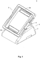
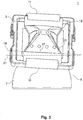
- Fig. 2 and Fig. 3 each show the mixing device 1 in a front view, wherein a container 12 is arranged in the form of a foil bag or bioreactor bag on the container carrier 3. In Fig. 3 If the positioning device 11 is shown in FIG Fig. 2 this is hidden.
- the container 12 is positioned with two opposite ends 15 by means of the positioning device 11 on the container carrier 3.
- the container 12 is fastened via flexible rods 35 (also called “rods"), which are inserted in tabs at the ends of the container 12, and the positioning device 11 in the form of clamping strips.
- the clamping bars 35 may be welded or welded into the container 12 or may be loosely inserted into plastic bottles.
- the positioning device 11 in particular in cooperation with the clamping bars 35, the position of the container 12 on the container carrier 3 is predetermined, and the removal side 17 of the container 12 is disposed along the predetermined line 19 of the container carrier 3.
- the removal pivot axis 21 is inclined relative to the predetermined line 19 or the removal side 17. From the in Fig. 2 and Fig. 3 given angle, the exact pivot axis angle is not recognizable. This would only be recognizable if the container carrier 3 would be placed perpendicular to the horizontal plane, ie perpendicular to the viewing direction in Fig. 2 and Fig. 3 would be arranged. In the exemplary embodiment, the removal pivot axis 21 horizontally aligned.
- the removal pivot axis 21 is predetermined by the pivot bearing between the container carrier 3 and the coupling element 9. If no mixing movement is carried out, the removal pivot axis 21 is fixed, in particular the removal pivot axis 21 does not move when the container carrier 3 is displaced from the mixing position into the removal position.
- Im in Fig. 2 and Figure 3 shown state is the container carrier 3 in the removal position or the intermediate layer, ie, the container 12 is in the removal position or in an intermediate position.
- the removal side 17 is inclined to the horizontal plane, in particular inclined to the removal region 23 out.
- Fig. 4 shows the mixing device 1 in a further perspective view from a different angle.
- the coupling element 9 is plate-shaped and is mounted pivotably about the tilting axis 25 on the base 7 of the movement device 5.
- the drive 27 generates a tilting movement of the coupling element 9 about the tilting axis 25 for generating the mixing movement.
- the removal pivot axis 21 is arranged.
- the removal pivot axis 21 and the tilt axis 25 are thus in the same horizontal plane.
- the removal pivot axis 21, however, is inclined about the pivot axis angle to the tilt axis 25.
- the removal pivot axis 21 is also inclined to the predetermined line, not shown, about the pivot axis angle.
- the mixing device 1 In the mixed position, the predetermined line and the tilting axis 25 are arranged parallel to each other.
- the underside of the container carrier 3 rests on the support region 31 of the coupling element 9 and is supported by it.
- the mixing device 1 has an erection mechanism 29 in the form of a gas pressure spring 29.
- the gas spring 29 is attached at one end to the coupling element 9 and at the other end to the underside of the container carrier 3.
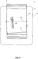
- Fig. 5 shows the mixing device 1 in a plan view.
- the removal pivot axis 21 is arranged inclined to the pivot axis 25 about the pivot axis angle.
- the gas spring 29 is oriented such that by linear method of the gas spring 29 of the container carrier 3 from the mixed position into the removal position can be relocated.
- the gas spring 29 in the initial position ie when the container carrier 3 is in the mixed position and the gas spring 29 is arranged parallel to the coupling element 9 in the horizontal plane, inclined approximately to the pivot axis angle to a line which is perpendicular to the tilt axis 25 and / or the predetermined line is.
- the gas spring-pivot axis is arranged approximately parallel to the removal pivot axis 21.
Description
Die vorliegende Erfindung betrifft eine Mischvorrichtung zum Mischen eines Inhalts eines Behälters.The present invention relates to a mixing device for mixing a content of a container.
In vielen industriellen Bereichen werden Behältnisse zur Durchmischung oder Umwälzung von Stoffen verwendet. Bei der Herstellung von Kulturmedien für Microorganismen oder bei kontrollierten biotechnologischen Prozessen wie der Zellkultivierung kommt der Durchmischung bzw. dem Umwälzen des Behälterinhaltes eine besondere Bedeutung zu. Aufgrund der unterschiedlichen Ausgangskonzentrationen der Stoffe sowie der Stoffwechselaktivität der Mikroorganismen während der Kultivierung kommt es zu lokalen Konzentrationsänderungen verschiedenster chemischer Komponenten im Medienansatz oder von Nährstoffen, Sauerstoff und den entstehenden Metaboliten während der Kultivierung. Um im gesamten Behältnis gleiche oder zumindest kontrollierte Konzentrationsbedingungen zu gewährleisten, ist es erforderlich, die Flüssigkeit oder Suspension im Behälter während des gesamten Prozesses durchzumischen bzw. umzuwälzen.In many industrial areas, containers are used for mixing or circulating materials. In the production of culture media for microorganisms or controlled biotechnological processes such as cell cultivation of the mixing or the circulation of the container contents is of particular importance. Due to the different initial concentrations of the substances and the metabolic activity of the microorganisms during cultivation, there are local concentration changes of various chemical components in the media mixture or of nutrients, oxygen and the resulting metabolites during cultivation. In order to ensure the same or at least controlled concentration conditions in the entire container, it is necessary to mix or circulate the liquid or suspension in the container during the entire process.
Der Einsatz von flexiblen Einwegbioreaktoren aus Folien nimmt dabei insbesondere im Hinblick auf die ständig steigenden Anforderungen an die Sterilität der Prozesse in der Bioverfahrenstechnik gegenüber starren Behältern aus Glas oder Edelstahl stetig an Bedeutung zu. Neben der guten Sterilisierbarkeit bieten die Folienbeutel weitere Vorteile wie die kostengünstige Herstellung, die einfache und platzsparende Lagerung, die weitestgehende Sicherheit gegenüber Kontamination und den Entfall einer aufwendigen Reinigung nach dem Gebrauch.The use of flexible disposable bioreactors made of films is steadily increasing in importance, particularly in view of the ever increasing demands on the sterility of the processes in bioprocessing technology over rigid containers made of glass or stainless steel. In addition to good sterilizability, the film bags offer further advantages such as the cost-effective production, the simple and space-saving storage, the greatest possible protection against contamination and the elimination of a costly cleaning after use.
Die Durchmischung des Inhaltes der flexiblen Einwegbioreaktoren erfolgt sowohl mechanisch unter Zuhilfenahme von Rührorganen als auch über die Bewegung des Behälters mit der darin enthaltenen Flüssigkeit selbst. Insbesondere bei der Verwendung von flexiblen Behältern zum Einmalgebrauch wird der Einsatz von rührerlosen Mischern als vorteilhaft angesehen, da keine Durchgänge durch die Behälterwand zum Antreiben von Rührelementen notwendig sind. Je nach Art der Bewegung sind derartige Mischer als Rocker, Plattformschüttler, Taumelmischer, Kreisschüttler, Vibrationsschüttler, Horizontalschüttler, Orbital-Shaker etc., bekannt.The mixing of the contents of the flexible disposable bioreactors is carried out both mechanically with the aid of stirrers as well as the movement of the container with the liquid contained therein itself. Especially when using flexible containers for single use, the use of stirrerless mixers is considered to be advantageous because no passages through the container wall for driving stirring elements are necessary. Depending on the type of movement, such mixers are known as rockers, platform shakers, tumble mixers, orbital shakers, vibratory shakers, horizontal shakers, orbital shakers, etc.
Flexible Behälter können je nach Einsatzgebiet verschiedene Größen aufweisen, wobei größere Behälter Volumina von mehreren Litern aufweisen können. Die meistens vorher befüllten Behälter werden üblicherweise auf plattenförmigen oder wannenförmigen beweglichen Trägern angeordnet, wobei sie z.B. mittels Klemmen oder Haken oder sonstigen lösbaren Befestigungsmitteln auf den Trägern fixiert werden. Die Träger werden angetrieben und erzeugen die Mischbewegung des Inhalts des Behälters. Der Träger führt hierbei beispielsweise eine Wippbewegung um eine horizontale Lage aus.Flexible containers may vary in size depending on the application, with larger containers having volumes of several liters. The most previously filled containers are usually placed on plate-shaped or trough-shaped movable supports, e.g. be fixed by clamps or hooks or other releasable fasteners on the carriers. The carriers are driven and produce the mixing movement of the contents of the container. The carrier carries out, for example, a rocking movement about a horizontal position.
Um den Inhalt der Beutel wieder zu entnehmen, lassen sich die Träger mit den darauf fixierten Beuteln in eine nahezu vertikale Position bewegen. Auch ein Befüllen der Behälter in der vertikalen Position ist ggf. möglich.In order to remove the contents of the bag, the carriers can be moved with the bags fixed thereon in a nearly vertical position. It may also be possible to fill the containers in the vertical position.
Es ist Aufgabe der vorliegenden Erfindung, eine verbesserte Mischvorrichtung bereitzustellen, welche auf einfache Weise einen Behälter in eine vorteilhafte Befüll- bzw. Entnahmestellung verlagern kann.It is an object of the present invention to provide an improved mixing device which can easily displace a container into an advantageous filling or removal position.
Diese Aufgabe wird durch den Gegenstand des unabhängigen Anspruchs gelöst. Bevorzugte Ausführungsformen ergeben sich aus den abhängigen Ansprüchen.This object is solved by the subject matter of the independent claim. Preferred embodiments will be apparent from the dependent claims.
Gemäß der vorliegenden Erfindung wird eine Mischvorrichtung zum Mischen eines Inhalts eines Behälters bereitgestellt, aufweisend: einen Behälter-Träger zum Tragen des Behälters; und eine Bewegungsvorrichtung, welche zum Bewegen des Behälter-Trägers mit dem Behälter-Träger verbunden ist, um den Inhalt des Behälters in einer Mischstellung mischen zu können; wobei der Behälter-Träger eine Positioniervorrichtung aufweist, welche ausgelegt ist, den Behälter in einer vorbestimmten bzw. vorbestimmbaren Lage an dem Behälter-Träger zu positionieren, so dass eine Entnahmeseite des Behälters im Wesentlichen entlang einer vorbestimmten Linie des Behälter-Trägers angeordnet ist, wobei der Behälter-Träger um eine Entnahme-Schwenkachse schwenkbar relativ zu der Bewegungsvorrichtung gelagert ist, um den daran positionierbaren Behälter in eine Entnahmestellung verlagern zu können, wobei die Entnahme-Schwenkachse derart in einem Schwenkachsenwinkel von über 0° bis 45° zur vorbestimmten Linie des Behälter-Trägers angeordnet ist, dass der daran positionierbare Behälter von der Mischstellung mittels einer Schwenkbewegung des Behälter-Trägers um die Entnahme-Schwenkachse in die Entnahmestellung verlagerbar ist, in der die Entnahmeseite an der unteren Seite des Behälters befindlich sowie zu einem Entnahmebereich des Behälters hin geneigt ist.According to the present invention, there is provided a mixing apparatus for mixing a contents of a container, comprising: a container carrier for carrying the container; and a moving device connected to move the container carrier with the container carrier to mix the contents of the container in a mixing position; the container carrier having a positioning device adapted to position the container in a predetermined position on the container carrier such that a withdrawal side of the container is disposed substantially along a predetermined line of the container carrier the container carrier is pivotally mounted about a take-off pivot axis relative to the moving device to move the positionable container into a removal position, wherein the removal pivot axis in such a pivot axis angle of about 0 ° to 45 ° to the predetermined line of the container Carrier is arranged so that the positionable container can be moved from the mixing position by means of a pivoting movement of the container carrier to the removal pivot axis in the removal position in which the removal side located on the lower side of the container and to a Removal of the container is inclined.
Bei dem Behälter kann es sich insbesondere um einen Bioreaktorbehälter handeln, wobei dieser aus einem Folienmaterial hergestellt sein kann. Ein derartiger Behälter kann als Beutel mit zumindest an zwei gegenüberliegenden Seiten verschweißten Rändern ausgeführt sein. Der Behälter kann eine vorbestimmte Auflagefläche aufweisen, auf welcher der Behälter stabil auf einer horizontalen Fläche abgelegt werden kann. Die Auflagefläche kann insbesondere eine seiner größten Oberflächen bzw. Seitenflächen sein. Die Auflagefläche und/oder die der Auflagefläche gegenüberliegende Fläche können Durchgänge und Anschlüsse für Zufuhr- und/oder Abfuhrleitungen und/oder Sensoren aufweisen. Sofern sich die Zufuhr- und/oder Abfuhrleitungen an der Auflagefläche befinden, verfügt auch der Behälter-Träger über entsprechende Durchgänge für die angeschlossenen Leitungen. Der Behälter kann mit seiner Auflagefläche auf dem Behälter-Träger angeordnet werden. Der Behälter kann in der Draufsicht eine im Wesentlichen viereckige Form mit vier Seitenkanten aufweisen. Insbesondere kann der Behälter in der Draufsicht symmetrisch ausgebildet sein, was für eine gleichmäßige Bewegung des Inhalts des Behälters während des Mischens vorteilhaft ist. Zumindest weist der Behälter eine Entnahmeseite auf. Die Entnahmeseite kann eine im Wesentlichen gerade Seitenkante des Behälters sein, wobei eine Seitenkante des Behälterinnenraums gemeint ist. Die Entnahmeseite bezeichnet die Seite des Behälters, welche zum Sammeln und zur Entnahme des Inhalts des Behälters und insbesondere der Produkte, die sich im Behälter gebildet haben, vorgesehen ist. Der Entnahmebereich des Behälters kann in einer der zwei Ecken der Entnahmeseite angeordnet sein. Am Entnahmebereich kann ein Auslass angeordnet sein, aus welchem der Inhalt des Behälters ausgelassen werden können.The container may, in particular, be a bioreactor container, which may be made of a film material. Such a container can be welded as a bag with at least two opposite sides Be executed edges. The container may have a predetermined bearing surface on which the container can be stored stably on a horizontal surface. The support surface may in particular be one of its largest surfaces or side surfaces. The support surface and / or the surface opposite the support surface may have passages and connections for supply and / or discharge lines and / or sensors. If the supply and / or discharge lines are located on the support surface, the container carrier also has corresponding passages for the connected lines. The container can be arranged with its bearing surface on the container carrier. The container may have in plan view a substantially quadrangular shape with four side edges. In particular, the container may be formed symmetrically in plan view, which is advantageous for a uniform movement of the contents of the container during mixing. At least the container has a removal side. The removal side may be a substantially straight side edge of the container, wherein a side edge of the container interior is meant. The withdrawal side refers to the side of the container which is provided for collection and removal of the contents of the container and in particular of the products which have formed in the container. The removal area of the container can be arranged in one of the two corners of the removal side. At the removal area, an outlet can be arranged, from which the contents of the container can be omitted.
Vorzugsweise wird der an dem Behälter-Träger positionierte Behälter zusammen mit dem Behälter-Träger zur Entnahme in die Entnahmestellung verlagert. Ein Befüllen des Behälters ist jedoch ebenfalls in dieser Stellung über die am Behälter angeordneten Zufuhrleitungen möglich.Preferably, the container positioned on the container carrier is displaced together with the container carrier for removal into the removal position. However, a filling of the container is also possible in this position via the supply lines arranged on the container.
Der Inhalt des Behälters kann eine Flüssigkeit oder eine Suspension sein. Der Behälter kann ferner ein Gas bzw. Gase enthalten. Der Inhalt des Behälters wird mittels der Mischvorrichtung gemischt bzw. umgewälzt, wodurch insbesondere bei der Zellkultivierung eine gute Sauerstoffdurchmischung gewährleistet werden kann.The contents of the container may be a liquid or a suspension. The container may further contain a gas or gases. The content of the container is mixed or circulated by means of the mixing device, whereby a good oxygen mixing can be ensured in particular during cell cultivation.
Der Behälter-Träger ist derart ausgebildet, dass der Behälter darauf angeordnet werden kann. Der Behälter-Träger kann derart ausgebildet sein, dass der Behälter mit seiner dem Behälter-Träger zugewandten größten Fläche bzw. seiner Auflagefläche im Wesentlichen vollständig an der oberen Fläche des Behälter-Trägers anliegt. Die obere Fläche des Behälter-Trägers kann als Aufnahmefläche bezeichnet werden. Der Behälter-Träger kann beispielsweise platten- oder wannenförmig ausgebildet sein und in der Draufsicht im Wesentlichen viereckig ausgeführt sein. Die wannenförmigen Behälter-Träger dienen im Wesentlichen dazu, bei Leckagen der Behälter das austretende Fluid aus den Behältern aufzunehmen. Es sind jedoch auch wannenförmige Behälter-Träger mit einer oder mehreren offenen Ecken bzw. Durchbrüchen möglich, über die in der Aufstellposition die Abfuhrleitungen geführt werden um so eine Entnahme aus dem Behälter zu erleichtern. Die Größe des Behälter-Trägers ist nicht beschränkt und kann in Abhängigkeit von der Behältergröße gewählt werden. Vorzugsweise entspricht die Form und Größe des Behälter-Trägers in der Draufsicht im Wesentlichen der Form und Größe des Behälters in der Draufsicht.The container carrier is designed such that the container is arranged thereon can be. The container carrier may be formed such that the container with its container carrier facing the largest surface or its support surface substantially completely rests against the upper surface of the container carrier. The upper surface of the container carrier may be referred to as a receiving surface. The container carrier may for example be formed plate-shaped or trough-shaped and executed in the plan view is substantially square. Essentially, the trough-shaped container carriers serve to absorb the escaping fluid from the containers in the event of leaks in the containers. However, there are also trough-shaped container carrier with one or more open corners or openings possible over which the discharge lines are guided in the installation position so as to facilitate removal from the container. The size of the container carrier is not limited and may be selected depending on the container size. Preferably, the shape and size of the container carrier in the plan view corresponds substantially to the shape and size of the container in plan view.
Die Bewegungsvorrichtung ist ausgelegt, den Behälter-Träger zum Ausführen der Mischbewegung zu bewegen. Hierzu ist die Bewegungsvorrichtung, vorzugsweise über ein bewegliches Kopplungselement, mit dem Behälter-Träger verbunden. Beim Bewegen des Behälters zum Mischen des Inhalts des Behälters ist der Behälter-Träger in einer Mischlage, und der darauf positionierte Behälter ist in einer Mischstellung. In der Mischlage ist der Behälter-Träger, bzw. die Aufnahmefläche davon, im Wesentlichen horizontal ausgerichtet. Genauer gesagt führt der Behälter-Träger in der Mischlage zum Mischen eine Bewegung um oder in der horizontalen Ebene aus. Je nach Art der Bewegung kann die Mischvorrichtung als Rocker, Plattformschüttler, Taumelmischer, Kreisschüttler, Vibrationsschüttler, Horizontalschüttler, Orbital-Shaker etc., bezeichnet werden. Bei einem Rocker führt der Behälter-Träger eine Kipp- oder Wipp-Bewegung um eine im Wesentlichen horizontalen Achse aus, wobei der Behälter-Träger zunächst in einem Bereich von etwa 0-15°, vorzugsweise in einem Bereich von etwa 0-10°, zur horizontalen Ebene geneigt wird, und anschließend in umgekehrter Richtung in einem Bereich von etwa 0-15°, vorzugsweise in einem Bereich von etwa 0-10°, zur horizontalen Ebene geneigt wird. Diese Bewegung des Behälter-Trägers wird auf den Behälter übertragen, so dass eine Wellenbewegung des Inhalts des Behälters erzeugt werden kann. Die Mischbewegung des Behälter-Trägers muss jedoch nicht zwingend ein Neigen zur horizontalen Ebene beinhalten, und der Behälter-Träger kann stattdessen auch in der horizontalen Ebene linear oder kreisförmig hin und her bewegt werden und/oder horizontal ausgerichtet in vertikaler Richtung hin und her bewegt bzw. geschüttelt werden. Mischformen der Bewegungsarten sind ebenfalls möglich. Die Mischlage ist durch die Bewegung des Behälter-Trägers also veränderbar, liegt aber im Wesentlichen in der horizontalen Ebene bzw. weicht nur geringfügig von dieser ab. Vorzugsweise weist der Behälter-Träger eine vorbestimmte bzw. vorbestimmbare Ruhelage auf, welche eingenommen wird, wenn der Behälter-Träger in der Mischlage keine Mischbewegung ausführt. In der Ruhelage befindet sich der auf dem Behälter-Träger angeordnete Behälter in einer Ruhestellung. In der Ruhelage bzw. Ruhestellung ist der Behälter-Träger bzw. der Behälter vorzugsweise etwa horizontal ausgerichtet. Entsprechendes gilt für die Mischstellung des auf dem Behälter-Träger angeordneten Behälters.The moving device is configured to move the container carrier to perform the mixing movement. For this purpose, the movement device, preferably via a movable coupling element, connected to the container carrier. When moving the container to mix the contents of the container, the container carrier is in a mixing position and the container positioned thereon is in a mixing position. In the mixed position, the container carrier, or the receiving surface thereof, is oriented substantially horizontally. More specifically, in the mixing layer for mixing, the container carrier performs motion around or in the horizontal plane. Depending on the type of movement, the mixing device may be referred to as rocker, platform shaker, tumble mixer, orbital shaker, vibratory shaker, horizontal shaker, orbital shaker, etc. In a rocker, the container carrier performs a tilting or rocking motion about a substantially horizontal axis, with the container carrier initially in a range of about 0-15 °, preferably in a range of about 0-10 °, is inclined to the horizontal plane, and then in the opposite direction in a range of about 0-15 °, preferably in a range of about 0-10 °, is inclined to the horizontal plane. This movement of the container carrier is transmitted to the container, so that a wave motion of the Contents of the container can be generated. However, the mixing movement of the container support does not necessarily include inclining to the horizontal plane, and instead the container support may be reciprocated linearly or circularly in the horizontal plane and / or horizontally reciprocated in the vertical direction be shaken. Mixed forms of movement types are also possible. The mixed layer is thus changeable by the movement of the container carrier, but is substantially in the horizontal plane or differs only slightly from this. Preferably, the container carrier has a predetermined or predeterminable rest position, which is assumed when the container carrier performs no mixing movement in the mixing position. In the rest position, the container disposed on the container carrier is in a rest position. In the rest position or rest position, the container carrier or the container is preferably oriented approximately horizontally. The same applies to the mixing position of the arranged on the container carrier container.
Zum Positionieren bzw. Fixieren des Behälters an dem Behälter-Träger weist der Behälter-Träger eine Positioniervorrichtung auf, welche jeweils an einer oder an mehreren Seiten des Behälter-Trägers vorgesehen sein kann. Die Positioniervorrichtung kann beispielsweise Klemmen, Klemmschienen und/oder Befestigungshaken aufweisen. Insbesondere kann die Positioniervorrichtung ein lösbares Positionieren bzw. Fixieren des Behälters an dem Behälter-Träger ermöglichen. Die Positioniervorrichtung ist ausgelegt, den Behälter in einer vorbestimmten bzw. vorbestimmbaren Lage an bzw. auf dem Behälter-Träger zu positionieren, so dass die Entnahmeseite des Behälters im Wesentlichen entlang einer vorbestimmten gedachten Linie des Behälter-Trägers angeordnet ist. Die vorbestimmte Linie ist eine gedachte Linie und muss nicht auf dem Behälter-Träger sichtbar sein. Entlang dieser gedachten Linie des Behälter-Trägers erstreckt sich die Entnahmeseite des Behälters, insbesondere die im Wesentlichen gerade Seitenkante des Behälterinnenraums, wenn der Behälter mittels der Positioniervorrichtung an dem Behälter-Träger positioniert ist.For positioning or fixing the container to the container carrier, the container carrier has a positioning device, which can be provided in each case on one or more sides of the container carrier. The positioning device may have, for example, terminals, clamping rails and / or fastening hooks. In particular, the positioning device can enable releasable positioning or fixing of the container to the container carrier. The positioning device is adapted to position the container in a predetermined position on the container carrier such that the withdrawal side of the container is disposed substantially along a predetermined imaginary line of the container carrier. The predetermined line is an imaginary line and does not need to be visible on the container carrier. Along this imaginary line of the container carrier extends the removal side of the container, in particular the substantially straight side edge of the container interior, when the container is positioned by means of the positioning device on the container carrier.
Die vorbestimmte Linie kann mit einer Seitenkante des Behälter-Trägers an der Entnahmeseite übereinstimmen, oder parallel zu dieser verlaufen. Die Entnahme-Schwenkachse kann in diesem Fall auch in Bezug auf die Seitenkante des Behälter-Trägers definiert werden, nämlich dass die Entnahme-Schwenkachse in einem Winkel von über 0° bis 45°, vorzugsweise etwa 1° bis etwa 15°, besonders bevorzugt etwa 3° bis etwa 10°, zur Seitenkante des Behälter-Trägers angeordnet ist.The predetermined line may be connected to a side edge of the container carrier on the Matching page, or parallel to this. The removal pivot axis can also be defined in this case with respect to the side edge of the container carrier, namely that the removal pivot axis at an angle of about 0 ° to 45 °, preferably about 1 ° to about 15 °, more preferably about 3 ° to about 10 °, is arranged to the side edge of the container carrier.
Die vorbestimmte Linie kann auch mit der Erstreckungsrichtung einer Klemmschiene der Positioniervorrichtung übereinstimmen oder parallel zu dieser verlaufen. Die Entnahme-Schwenkachse kann in diesem Fall auch in Bezug auf die Erstreckungsrichtung der Klemmschiene definiert werden, nämlich dass die Entnahme-Schwenkachse in einem Winkel von über 0° bis 45°, vorzugsweise etwa 1° bis etwa 15°, besonders bevorzugt etwa 3° bis etwa 10°, zur Erstreckungsrichtung der Klemmschiene angeordnet ist.The predetermined line can also coincide with the extension direction of a clamping rail of the positioning device or run parallel to it. The removal pivot axis can also be defined in this case with respect to the extension direction of the clamping rail, namely that the removal pivot axis at an angle of about 0 ° to 45 °, preferably about 1 ° to about 15 °, more preferably about 3 ° is arranged to about 10 °, to the extension direction of the clamping rail.
Der Behälter-Träger kann einen Anschlag für die Entnahmeseite des Behälters aufweisen, wobei in diesem Fall die vorbestimmte Linie mit der Erstreckungsrichtung des Anschlags übereinstimmen oder parallel zu dieser verlaufen kann. Die Entnahme-Schwenkachse kann in diesem Fall auch in Bezug auf die Erstreckungsrichtung des Anschlags definiert werden, nämlich dass die Entnahme-Schwenkachse in einem Winkel von über 0° bis 45°, vorzugsweise etwa 1° bis etwa 15°, besonders bevorzugt etwa 3° bis etwa 10°, zur Erstreckungsrichtung des Anschlags angeordnet ist.The container carrier may have a stop for the removal side of the container, in which case the predetermined line may coincide with the direction of extension of the stop or may be parallel thereto. The removal pivot axis can also be defined in this case with respect to the extension direction of the stop, namely that the removal pivot axis at an angle of about 0 ° to 45 °, preferably about 1 ° to about 15 °, more preferably about 3 ° is arranged to about 10 °, to the extension direction of the stop.
Falls der Behälter-Träger in der Draufsicht eine symmetrische Ausbildung hat, kann die vorbestimmte Linie parallel zu einer Symmetrieachse des Behälter-Trägers verlaufen. Die Entnahme-Schwenkachse kann in diesem Fall auch in Bezug auf die Symmetrieachse des Behälter-Trägers definiert werden, nämlich dass die Entnahme-Schwenkachse in einem Winkel von über 0° bis 45°, vorzugsweise etwa 1° bis etwa 15°, besonders bevorzugt etwa 3° bis etwa 10°, zur Symmetrieachse des Behälter-Trägers angeordnet ist.If the container carrier has a symmetrical design in plan view, the predetermined line may be parallel to an axis of symmetry of the container carrier. The removal pivot axis can also be defined in this case with respect to the symmetry axis of the container carrier, namely that the removal pivot axis at an angle of about 0 ° to 45 °, preferably about 1 ° to about 15 °, more preferably about 3 ° to about 10 °, is arranged to the axis of symmetry of the container carrier.
Der Behälter-Träger ist schwenkbar an der Bewegungsvorrichtung gelagert und kann relativ zu der Bewegungsvorrichtung verschwenkt werden. Diese Schwenkbewegung ist unabhängig von der Mischbewegung des Behälter-Trägers und wird grundsätzlich nicht während der Mischbewegung ausgeführt. Die Schwenkbarkeit des Behälter-Trägers gegenüber der Bewegungsvorrichtung ermöglicht ein Verlagern des Behälter-Trägers von der Mischlage in eine Entnahmelage. Entsprechend ermöglicht die Schwenkbarkeit des Behälter-Trägers gegenüber der Bewegungsvorrichtung ein Verlagern des auf dem Behälter-Träger angeordneten Behälters von einer Mischstellung in eine Entnahmestellung. Das Verlagern von der Mischlage bzw. Mischstellung in die Entnahmelage bzw. Entnahmestellung kann auch als "Aufstellen" bezeichnet werden.The container carrier is pivotally mounted on the moving device and can be pivoted relative to the moving device. This pivoting movement is independent of the mixing movement of the container carrier and is basically not carried out during the mixing movement. The pivotability of the container carrier relative to the movement device allows a displacement of the container carrier from the mixing layer into a removal position. Accordingly, the pivotability of the container carrier relative to the movement device allows a displacement of the arranged on the container carrier container from a mixing position to a removal position. The shifting from the mixing position or mixing position into the removal position or removal position can also be referred to as "erection".
In der Entnahmestellung ist der Behälter derart ausgerichtet, dass die Entnahmeseite in vertikaler Richtung an der unteren Seite des Behälters befindlich ist sowie zu einem Entnahmebereich des Behälters hin geneigt ist. Der Entnahmebereich kann im Bereich einer der unteren Ecken des Behälters angeordnet sein, wobei der Entnahmebereich direkt in der Ecke selbst oder an der oberen Fläche oder Auflagefläche des Behälters nahe der Ecke angeordnet sein kann. In der Entnahmestellung ist die Auflagefläche des Behälters in einem steilen Winkel zur horizontalen Ebene geneigt, und die Entnahmeseite des Behälters bildet die untere Seite bzw. Kante des Behälters. Die Entnahmeseite des Behälters ist zu der horizontalen Ebene geneigt, jedoch in einem flacheren Winkel. Wenn die Auflagefläche in etwa senkrecht zur horizontalen Ebene aufgestellt ist, entspricht der Neigungswinkel der Entnahmeseite zur horizontalen Ebene in etwa dem Schwenkachsenwinkel zwischen der Entnahme-Schwenkachse und der vorbestimmten Linie des Behälter-Trägers. Wenn die Auflagefläche weniger als 90° zur horizontalen Ebene geneigt ist, ist der Neigungswinkel der Entnahmeseite zur horizontalen Ebene geringer als der Schwenkachsenwinkel zwischen der Entnahme-Schwenkachse und der vorbestimmten Linie des Behälter-Trägers. Die Auflagefläche des Behälters kann in der Entnahmestellung in einem Winkel von 30° bis 90°, vorzugsweise 35° bis 55°, zur horizontalen Ebene geneigt sein.In the removal position, the container is oriented such that the removal side is located in the vertical direction on the lower side of the container and is inclined to a removal region of the container. The removal region may be located in the region of one of the lower corners of the container, wherein the removal region may be located directly in the corner itself or on the upper surface or support surface of the container near the corner. In the removal position, the support surface of the container is inclined at a steep angle to the horizontal plane, and the withdrawal side of the container forms the lower side or edge of the container. The withdrawal side of the container is inclined to the horizontal plane, but at a shallower angle. When the support surface is set approximately perpendicular to the horizontal plane, the inclination angle of the extraction side to the horizontal plane approximately corresponds to the pivot axis angle between the extraction pivot axis and the predetermined line of the container support. When the support surface is inclined less than 90 ° to the horizontal plane, the inclination angle of the extraction side to the horizontal plane is less than the pivot axis angle between the extraction pivot axis and the predetermined line of the container support. The support surface of the container may be inclined in the removal position at an angle of 30 ° to 90 °, preferably 35 ° to 55 ° to the horizontal plane.
In anderen Worten ausgedrückt ist in der Entnahmelage die Aufnahmefläche des Behälter-Trägers in einem steilen Winkel zur horizontalen Ebene geneigt, und die vorbestimmte Linie des Behälter-Trägers ist ebenfalls zu der horizontalen Ebene geneigt, jedoch in einem flacheren Winkel. Wenn die Aufnahmefläche in etwa senkrecht zur horizontalen Ebene aufgestellt ist, entspricht der Neigungswinkel der vorbestimmten Linie zur horizontalen Ebene in etwa dem Schwenkachsenwinkel zwischen der Entnahme-Schwenkachse und der vorbestimmten Linie. Wenn die Aufnahmefläche weniger als 90° zur horizontalen Ebene geneigt ist, ist der Neigungswinkel der vorbestimmten Linie zur horizontalen Ebene geringer als der Schwenkachsenwinkel zwischen der Entnahme-Schwenkachse und der vorbestimmten Linie. Die Aufnahmefläche des Behälter-Trägers kann in der Entnahmelage in einem Winkel von 30° bis 90°, vorzugsweise 35° bis 55°, zur horizontalen Ebene geneigt sein.In other words, in the picking position, the receiving surface of the container carrier is inclined at a steep angle to the horizontal plane, and the predetermined line of the container carrier is also to the horizontal plane inclined, but at a shallower angle. When the receiving surface is set approximately perpendicular to the horizontal plane, the inclination angle of the predetermined line to the horizontal plane approximately corresponds to the pivot axis angle between the take-off pivot axis and the predetermined line. When the receiving surface is inclined at less than 90 ° to the horizontal plane, the inclination angle of the predetermined line to the horizontal plane is less than the pivot axis angle between the unloading pivot axis and the predetermined line. The receiving surface of the container carrier may be inclined in the removal position at an angle of 30 ° to 90 °, preferably 35 ° to 55 ° to the horizontal plane.
Da in der Mischlage bzw. Ruhelage, d.h. wenn der Behälter in der Mischstellung bzw. Ruhestellung ist, der Behälter-Träger (bzw. die Aufnahmefläche davon) im Wesentlichen zur horizontalen Ebene ausgerichtet ist, gelten die obigen Ausführungen zu den Neigungen in Relation zu der horizontalen Ebene im Wesentlichen auch für die Neigungen in Relation zu der Mischlage bzw. Ruhelage.Since in the mixed position or rest position, i. when the container is in the mixing position or rest position, the container support (or the receiving surface thereof) is oriented substantially to the horizontal plane, the above explanations regarding the inclinations in relation to the horizontal plane essentially also apply to the inclinations in Relation to the mixed position or rest position.
Die Entnahme-Schwenkachse ist in einem Schwenkachsenwinkel von über 0° bis 45° zur vorbestimmten Linie des Behälter-Trägers angeordnet, wobei hier der kleinste Winkel (d.h. ein Winkel zwischen 0° und 90°) zwischen der Entnahme-Schwenkachse und der vorbestimmten Linie gemeint ist. Falls sich die Entnahme-Schwenkachse und die vorbestimmte Linie nicht im Raum schneiden, also windschief sind, ist der Schwenkachsenwinkel als der Winkel zwischen den Richtungsvektoren der Entnahme-Schwenkachse und der vorbestimmten Linie zu bestimmen. In anderen Worten ist der Schwenkachsenwinkel der größte ermittelbare Winkel zwischen 0° und 90° zwischen den projizierten Linien der Entnahme-Schwenkachse und der vorbestimmten Linie auf sämtlichen möglichen Ebenen im Raum.The take-off pivot axis is located at a pivot axis angle greater than 0 ° to 45 ° to the predetermined line of the container support, here the smallest angle (ie, an angle between 0 ° and 90 °) between the take-off pivot axis and the predetermined line is. If the extraction pivot axis and the predetermined line do not intersect in space, that is skew, the pivot axis angle is to be determined as the angle between the direction vectors of the extraction pivot axis and the predetermined line. In other words, the pivot axis angle is the largest detectable angle between 0 ° and 90 ° between the projected lines of the extraction pivot axis and the predetermined line on all possible planes in space.
Vorzugsweise entspricht der Schwenkachsenwinkel dem Winkel zwischen den auf die horizontale Ebene projizierten Linien der Entnahme-Schwenkachse und der vorbestimmten Linie, wenn der Behälter-Träger (bzw. die Aufnahmefläche davon) zur horizontalen Ebene ausgerichtet ist bzw. wenn der Behälter-Träger in der Mischlage oder Ruhelage ist. In anderen Worten ist vorzugsweise die Entnahme-Schwenkachse innerhalb der horizontalen Ebene gegenüber der vorbestimmten Linie um den Schwenkachsenwinkel geneigt, und weist keine Neigung gegenüber der horizontalen Ebene auf. Der Behälter-Träger und/oder die Bewegungsvorrichtung können ein Schwenklager aufweisen, welches den Behälter-Träger mit der Bewegungsvorrichtung verbindet, wobei die Schwenkachse des Schwenklagers der Entnahme-Schwenkachse entspricht.Preferably, the pivot axis angle corresponds to the angle between the lines projected on the horizontal plane of the extraction pivot axis and the predetermined line when the container support (or the receiving surface thereof) is aligned to the horizontal plane or if the container carrier in the mixed position or rest position. In other words, preferably, the take-off pivot axis is inclined within the horizontal plane from the predetermined line about the pivot axis angle, and has no inclination to the horizontal plane. The container carrier and / or the movement device may have a pivot bearing, which connects the container carrier with the movement device, wherein the pivot axis of the pivot bearing of the removal pivot axis corresponds.
Vorteilhafterweise ermöglicht die schräge Anordnung der Entnahme-Schwenkachse zur vorbestimmten Linie des Behälter-Trägers, dass der Behälter-Träger und der darauf positionierbare Behälter mittels einer einzigen Schwenkbewegung in eine vorteilhafte Entnahmelage bzw. Entnahmestellung verlagert werden kann. In der Entnahmelage ist der Behälter-Träger gegenüber der horizontalen Ebene aufgestellt. Der Behälter wird vorzugsweise in der horizontalen Position angebracht und entnommen. Es ist aber nicht auszuschließen, dass der Behälter auch in der Entnahmestellung am Behälter-Träger positioniert bzw. fixiert wird. Einfacher ist dies aber in der Ruhelage. Ferner ist in der Entnahmestellung die Entnahmeseite des Behälters zu einem Entnahmebereich hin geneigt, so dass der Entnahmebereich immer am tiefsten Punkt des Behälters angeordnet ist. Hierdurch können sich Zellen oder Metabolite, die sich aufgrund der Schwerkraft in dem Fluid oder der Suspension absetzen, auf vorteilhafte Weise in dem Entnahmebereich sammeln, was die Entnahme zusätzlich vereinfacht.Advantageously, the oblique arrangement of the removal pivot axis to the predetermined line of the container support that the container carrier and the positionable container can be moved by means of a single pivoting movement in an advantageous removal position or removal position. In the removal position of the container carrier is placed opposite the horizontal plane. The container is preferably mounted and removed in the horizontal position. However, it can not be ruled out that the container is also positioned or fixed in the removal position on the container carrier. But this is easier in the rest position. Further, in the removal position, the removal side of the container is inclined to a removal region, so that the removal region is always located at the lowest point of the container. As a result, cells or metabolites which settle in the fluid or suspension due to gravity can advantageously accumulate in the removal area, which further simplifies removal.
Vorzugsweise ist die Entnahme-Schwenkachse in einem Schwenkachsenwinkel von etwa 1° bis etwa 15°, besonders vorzugsweise etwa 3° bis etwa 10°, zur vorbestimmten Linie angeordnet.Preferably, the extraction pivot axis is disposed at a pivot axis angle of about 1 ° to about 15 °, more preferably about 3 ° to about 10 °, to the predetermined line.
Bei einem zu geringen Schwenkachsenwinkel kann in der Entnahmestellung die Neigung der Entnahmeseite zum Entnahmebereich hin für eine gute Sedimentation zu klein sein. Ein zu großer Schwenkachsenwinkel hingegen kann das Positionieren bzw. Fixieren des Behälters an dem Behälter-Träger erschweren, da der Behälter, der ein hohes Gewicht aufweisen kann, in einem stark von der horizontalen Ebene abweichenden Winkel an dem Behälter-Träger positioniert werden muss. Es hat sich herausgestellt, dass ein Schwenkachsenwinkel von etwa 1° bis etwa 15°, vorzugsweise etwa 3° bis etwa 10°, besonders vorteilhaft für das Sammeln von Produkten im Entnahmebereich und zur einfachen Positionierung des Behälters an dem Behälter-Träger ist.If the pivot axis angle is too small, the inclination of the removal side towards the removal region may be too small in the removal position for good sedimentation. On the other hand, too large a pivot axis angle may complicate the positioning or fixing of the container to the container support, since the container, which may have a high weight, in a strong from the horizontal plane deviating angle must be positioned on the container carrier. It has been found that a pivot axis angle of about 1 ° to about 15 °, preferably about 3 ° to about 10 °, is particularly advantageous for collecting products in the removal area and for easy positioning of the container on the container carrier.
Vorzugsweise ist die Bewegungsvorrichtung ausgelegt, den Behälter-Träger um eine im Wesentlichen horizontale Wippachse hin- und her zu bewegen, wobei die Wippachse im Wesentlichen parallel zur vorbestimmten Linie angeordnet ist.Preferably, the moving device is designed to move the container carrier back and forth about a substantially horizontal rocking axis, wherein the rocking axis is arranged substantially parallel to the predetermined line.
Bei der Wipp-Bewegung wird der Behälter-Träger zunächst um etwa 2° bis 15° zur horizontalen Ebene geneigt, und anschließend in umgekehrter Richtung um etwa 2° bis 15° zur horizontalen Ebene geneigt. Diese Bewegung des Behälter-Trägers kann wiederholt ausgeführt werden und auf den Behälter übertragen werden, so dass eine ständige Wellenbewegung des Inhalts des Behälters erzeugt werden kann. Die Wippachse kann durch die Bewegungsvorrichtung vorgegeben sein. Die Wippachse ist vorzugsweise mittig zum Behälter-Träger bzw. dem darauf positionierten Behälter angeordnet, so dass der in vertikaler Richtung zurückgelegte Weg der Entnahmeseite bei der Kippbewegung etwa dem in vertikaler Richtung zurückgelegten Weg der der Entnahmeseite gegenüberliegenden Seite des Behälters entspricht. Die Wippachse kann von der Aufnahmefläche des Behälter-Trägers in vertikaler Richtung beabstandet sein. Die Wippachse ist im Wesentlichen parallel zur vorbestimmten Linie angeordnet, so dass die Entnahme-Schwenkachse auch in Bezug auf die Wippachse definiert werden kann, nämlich dass die Entnahme-Schwenkachse in einem Winkel von über 0° bis 45°, vorzugsweise etwa 1° bis etwa 15°, besonders bevorzugt etwa 3° bis etwa 10°, zur Wippachse angeordnet ist.In the rocking movement, the container support is first inclined by about 2 ° to 15 ° to the horizontal plane, and then inclined in the opposite direction by about 2 ° to 15 ° to the horizontal plane. This movement of the container carrier may be carried out repeatedly and transferred to the container, so that a constant wave movement of the contents of the container can be generated. The rocking axis can be predetermined by the movement device. The rocking axis is preferably arranged centrally relative to the container carrier or the container positioned thereon so that the distance traveled in the vertical direction of the removal side during the tilting movement corresponds approximately to the distance traveled in the vertical direction of the removal side opposite side of the container. The rocking axis may be spaced from the receiving surface of the container carrier in the vertical direction. The rocking axis is arranged substantially parallel to the predetermined line, so that the removal pivot axis can also be defined with respect to the rocking axis, namely that the removal pivot axis at an angle of about 0 ° to 45 °, preferably about 1 ° to about 15 °, more preferably about 3 ° to about 10 °, is arranged to Wippachse.
Vorzugsweise weist die Bewegungsvorrichtung ein bewegliches Kopplungselement auf, welches zum Bewegen des Behälter-Trägers mit dem Behälter-Träger verbunden ist, wobei der Behälter-Träger um die Entnahme-Schwenkachse schwenkbar an dem Kopplungselement gelagert ist, so dass der Behälter-Träger mittels einer Schwenkbewegung von einer Mischlage in eine Entnahmelage verlagert werden kann.Preferably, the movement device comprises a movable coupling element, which is connected for moving the container carrier with the container carrier, wherein the container carrier is pivotally mounted about the removal pivot axis on the coupling element, so that the container carrier by means of a pivoting movement can be moved from a mixed layer into a picking situation.
Das Kopplungselement kann von einem Antrieb der Bewegungsvorrichtung angetrieben bzw. bewegt werden. Das Kopplungselement kann von einer Basis der Bewegungsvorrichtung nach oben vorstehen. Der Behälter-Träger ist über das Kopplungselement mit der Bewegungsvorrichtung verbunden, so dass die Bewegung des Kopplungselements auf den Behälter-Träger und weiter auf den Behälter übertragen werden kann.The coupling element can be driven or moved by a drive of the movement device. The coupling member may project upwardly from a base of the moving device. The container carrier is connected via the coupling element with the movement device, so that the movement of the coupling element can be transferred to the container carrier and further to the container.
Vorzugsweise weist die Positioniervorrichtung mindestens eine Klemmschiene auf, welche sich im Wesentlichen entlang der vorbestimmten Linie oder parallel dazu erstreckt.Preferably, the positioning device has at least one clamping rail, which extends substantially along the predetermined line or parallel thereto.
Mittels der Klemmschiene kann auf vorteilhafte Weise eine Seite des Behälters, insbesondere im Fall eines Folienbeutels, an dem Behälter-Träger fixiert werden. Vorzugsweise ist eine Klemmschiene an der Entnahmeseite des Behälters und eine Klemmschiene an der der Entnahmeseite gegenüberliegenden Seite des Behälters vorgesehen. Der Behälter kann an den entsprechenden Stellen Laschen oder Schienen aufweisen, die mit den Klemmschienen zusammenwirken können. In einer besonders bevorzugten Ausführungsform verfügt der Behälter in seiner Peripherie an mindestens 2 Seiten über in Laschen eingesteckte stabile Stäbe oder Stangen, die mit den Klemmschienen des Behälter-Trägers korrespondieren und von diesen eingeklemmt werden. Der Behälter wird so mithilfe der in den Klemmschienen fixierten Stäbe gehalten. Die stabilen Stäbe oder Stangen sind vorzugsweise aus Kunststoff.Advantageously, one side of the container, in particular in the case of a foil bag, can be fixed to the container carrier by means of the clamping rail. Preferably, a clamping rail is provided on the withdrawal side of the container and a clamping rail on the side opposite the removal side of the container. The container may have at the appropriate locations tabs or rails that can cooperate with the clamping rails. In a particularly preferred embodiment, the container has in its periphery on at least two sides via tabs inserted into tabs or rods which correspond to the clamping rails of the container carrier and are clamped by these. The container is held using the rods fixed in the clamping rails. The stable rods or rods are preferably made of plastic.
Vorzugsweise weist die Positioniervorrichtung zumindest einen Befestigungshaken auf, welcher im Wesentlichen entlang der vorbestimmten Linie oder parallel dazu angeordnet ist.Preferably, the positioning device has at least one attachment hook, which is arranged substantially along the predetermined line or parallel thereto.
Der Befestigungshaken ermöglicht ein besonders einfaches Fixieren einer Seite des Behälters an dem Behälter-Träger. Der Befestigungshaken kann eine sich in Breitenrichtung erstreckende Form aufweisen und/oder es können eine Mehrzahl von Befestigungshaken entlang der vorbestimmten Linie oder parallel dazu angeordnet sein. Vorzugsweise ist ein Befestigungshaken an der Entnahmeseite des Behälters und ein Befestigungshaken an der der Entnahmeseite gegenüberliegenden Seite des Behälters vorgesehen. Der Behälter kann Ausnehmungen, insbesondere Löcher und/oder Schlitze, aufweisen, in welche der oder die Befestigungshaken eingeführt werden können.The attachment hook enables a particularly simple fixing of one side of the container to the container carrier. The attachment hook may have a widthwise extending shape and / or a plurality of attachment hooks may be arranged along the predetermined line or parallel thereto be. Preferably, a fastening hook is provided on the withdrawal side of the container and a fastening hook on the side opposite the removal side of the container. The container may have recesses, in particular holes and / or slots, into which the attachment hook or hooks can be inserted.
Vorzugsweise ist der Behälter-Träger wannenförmig ausgebildet, und eine Innenkante des wannenförmigen Behälter-Trägers erstreckt sich im Wesentlichen entlang der vorbestimmten Linie oder parallel dazu.Preferably, the container support is trough-shaped, and an inner edge of the trough-shaped container support extends substantially along the predetermined line or parallel thereto.
Die Wannenform des Behälter-Trägers ermöglicht eine besonders gute Abstützung bei Behältern in Form von Folienbeuteln, da diese im befüllten und aufgeblasenen Zustand eine Auflagefläche aufweisen können, die der Wannenform entspricht. Ferner wird durch die Wannenform ein guter Seitenhalt des Behälters ermöglicht, was während der Mischbewegung und beim Aufstellen wichtig ist. Bei Leckagen bietet eine geschlossene Wanne eine zusätzliche Sicherheit vor sich weiter verbreitenden Kontaminationen mit dem Fluid aus dem Behälter. Da der Behälter in diesem Fall an der wannenförmigen Aufnahmefläche des Behälter-Trägers anliegt, erstreckt sich die Innenkante des Behälter-Trägers entlang der vorbestimmten Linie oder parallel dazu. In einer weiteren Ausführungsform ist der wannenförmige Behälter-Träger an einer oder mehreren Ecken offen, so dass in diesen Bereichen bequem Zufuhr- und/oder Abfuhrleitungen sowie Anschlüsse für diverse Sensorikelemente geführt werden können.The trough shape of the container carrier allows a particularly good support in containers in the form of foil bags, since they can have a bearing surface in the filled and inflated state, which corresponds to the trough shape. Furthermore, the trough shape allows a good lateral support of the container, which is important during the mixing movement and when setting up. In the case of leaks, a closed tray offers additional security against further spreading contamination with the fluid from the container. Since the container in this case bears against the trough-shaped receiving surface of the container carrier, the inner edge of the container carrier extends along the predetermined line or parallel thereto. In a further embodiment, the trough-shaped container carrier is open at one or more corners, so that in these areas convenient supply and / or discharge lines and connections for various sensor elements can be performed.
Vorzugsweise weist das Kopplungselement einen Auflagebereich auf, welcher an einer Unterseite des Behälter-Trägers anliegt und diesen stützt, wenn der an dem Behälter-Träger positionierbare Behälter sich in der Mischstellung befindet.Preferably, the coupling element has a support region which abuts against and supports a lower side of the container carrier when the container positionable on the container carrier is in the mixing position.
In anderen Worten stellt der Auflagebereich des Kopplungselements einen Anschlag für den Behälter-Träger dar, wenn der Behälter-Träger von der Entnahmelage in die Mischlage verlagert wird. Durch den Auflagebereich wird der Behälter-Träger in der Mischlage im Wesentlichen horizontal ausgerichtet. Hierbei wird der Behälter-Träger einerseits durch das Schwenklager zwischen Behälter-Träger und Kopplungselement und durch den Auflagebereich des Kopplungselements gestützt.In other words, the support area of the coupling element constitutes a stop for the container carrier when the container carrier is moved from the removal position into the mixing position. By the support area of the container carrier is aligned in the mixed position substantially horizontally. Here, the container carrier supported on the one hand by the pivot bearing between the container carrier and the coupling element and by the support region of the coupling element.
Vorzugsweise ist das Kopplungselement im Wesentlichen plattenförmig ausgebildet, wobei die Entnahme-Schwenkachse an einem Ende des plattenförmigen Kopplungselements angeordnet ist.Preferably, the coupling element is formed substantially plate-shaped, wherein the removal pivot axis is arranged at one end of the plate-shaped coupling element.
Im Wesentlichen plattenförmig bedeutet, dass das Kopplungselement eine flächige Ausbildung hat. Das Kopplungselement kann jedoch Ausnehmungen aufweisen oder eine Rahmenkonstruktion sein. Vorzugsweise ist das plattenförmige Kopplungselement im Wesentlichen zur horizontalen Ebene ausgerichtet, und an einem Ende des Kopplungselements ist die Entnahme-Schwenkachse bzw. das Schwenklager angeordnet. In der Mischlage kann der Behälter-Träger mit seiner Unterseite an dem Kopplungselement, insbesondere dem Auflagebereich davon, anliegen, wobei der Behälter-Träger parallel zum Kopplungselement ausgerichtet ist.Substantially plate-shaped means that the coupling element has a planar design. However, the coupling element may have recesses or be a frame construction. Preferably, the plate-shaped coupling element is oriented substantially to the horizontal plane, and at one end of the coupling element, the removal pivot axis or the pivot bearing is arranged. In the mixed position, the container carrier can rest with its underside on the coupling element, in particular the support area thereof, wherein the container carrier is aligned parallel to the coupling element.
Vorzugsweise umfasst die Mischvorrichtung einen Aufstellmechanismus, welcher es ermöglicht, den Behälter-Träger in einem vorbestimmten bzw. vorbestimmbaren Aufstellwinkel relativ zur Bewegungsvorrichtung festzustellen.Preferably, the mixing device comprises an erection mechanism, which makes it possible to determine the container carrier in a predetermined or predeterminable setting angle relative to the movement device.
Der Aufstellmechanismus ist vorzugsweise mit dem Kopplungselement verbunden und ermöglicht, den Behälter-Träger in einem vorbestimmten bzw. vorbestimmbaren Aufstellwinkel relativ zum Kopplungselement aufzustellen und/oder festzustellen. Der Aufstellmechanismus kann hydraulisch, pneumatisch und/oder elektrisch angetrieben sein und ein Aufstellen und/oder Feststellen des Behälter-Trägers in einem vorbestimmten bzw. vorbestimmbaren Aufstellwinkel ermöglichen. Der Aufstellmechanismus ist vorzugsweise zwischen dem Kopplungselement und dem Behälter-Träger angeordnet.The erection mechanism is preferably connected to the coupling element and makes it possible to set up and / or determine the container carrier in a predetermined or predeterminable setting angle relative to the coupling element. The erection mechanism can be hydraulically, pneumatically and / or electrically driven and allow setting up and / or fixing of the container carrier in a predetermined or predeterminable setting angle. The erection mechanism is preferably arranged between the coupling element and the container carrier.
Vorzugsweise weist der Aufstellmechanismus einen Hebel zur Arretierung bzw. einen Arretierhebel auf, welcher schwenkbar an der Bewegungsvorrichtung angeordnet ist, und welcher den Behälter-Träger stützt, wenn der an dem Behälter-Träger positionierbare Behälter sich in der Entnahmestellung befindet.Preferably, the jacking up mechanism comprises a locking lever which is pivotally mounted on the moving device and which supports the container carrier when attached to the container carrier positionable container is in the removal position.
Der Arretierhebel ist vorzugsweise schwenkbar an dem Kopplungselement angeordnet. Der Arretierhebel ermöglicht einen besonders einfachen Aufstellmechanismus, da der Behälter-Träger, insbesondere die Unterseite davon, nicht speziell konfiguriert werden muss. In der Mischlage ist der Arretierhebel im Wesentlichen horizontal und im Wesentlichen in derselben Ebene wie der Behälter-Träger und/oder das Kopplungselement ausgerichtet. Durch Aufschwenken des Arretierhebels wird der Behälter-Träger angehoben und um die Entnahme-Schwenkachse schwenkend aufgestellt, wobei der Arretierhebel an der Unterseite des Behälter-Trägers entlang gleitet. Vorzugsweise ist die Schwenkachse des Arretierhebels in etwa parallel zur Entnahme-Schwenkachse angeordnet.The locking lever is preferably arranged pivotably on the coupling element. The locking lever allows a particularly simple deployment mechanism, since the container support, in particular the underside thereof, does not need to be specially configured. In the mixing position, the locking lever is aligned substantially horizontally and substantially in the same plane as the container carrier and / or the coupling element. By pivoting the locking lever of the container support is raised and placed pivoting about the removal pivot axis, wherein the locking lever slides on the underside of the container support along. Preferably, the pivot axis of the locking lever is arranged approximately parallel to the removal pivot axis.
Im Folgenden wird ein Ausführungsbeispiel der vorliegenden Erfindung anhand der beigefügten Figuren näher beschrieben.In the following, an embodiment of the present invention will be described in more detail with reference to the accompanying figures.
Es zeigen:
- Fig. 1
- eine Mischvorrichtung gemäß eines Ausführungsbeispiels in einer perspektivischen Ansicht.
- Fig. 2
- die Mischvorrichtung mit einem darauf positionierten Behälter in einer Frontansicht.
- Fig. 3
- die Mischvorrichtung mit einem darauf positionierten Behälter in einer Frontansicht mit Klemmleisten.
- Fig. 4
- die Mischvorrichtung in einer weiteren perspektivischen Ansicht.
- Fig. 5
- die Mischvorrichtung in einer Draufsicht.
- Fig. 1
- a mixing device according to an embodiment in a perspective view.
- Fig. 2
- the mixing device with a container positioned thereon in a front view.
- Fig. 3
- the mixing device with a container positioned thereon in a front view with terminal strips.
- Fig. 4
- the mixing device in a further perspective view.
- Fig. 5
- the mixing device in a plan view.
- 11
- Mischvorrichtungmixing device
- 33
- Behälter-TrägerA container carrier,
- 55
- Bewegungsvorrichtungmover
- 77
- Basis der BewegungsvorrichtungBase of the movement device
- 99
- Kopplungselementcoupling element
- 1111
- Positioniervorrichtungpositioning
- 1212
- Behältercontainer
- 1515
- Behälterendecontainer end
- 1717
- Entnahmeseiteremoval side
- 1919
- vorbestimmte Liniepredetermined line
- 2121
- Entnahme-SchwenkachseRemoval pivoting axis
- 2323
- Entnahmebereichremoval area
- 2525
- Kippachsetilt axis
- 2727
- Antriebdrive
- 2929
- Aufstellmechanismus, GasdruckfederSet-up mechanism, gas spring
- 3131
- Auflagebereichsupport area
- 3333
- Ausnehmungrecess
- 3535
- Klemmstabclamping bar
Claims (11)
- A mixing device (1) for mixing a content of a container (12), comprising:a container support (3) for supporting the container (12); anda moving device (5) connected to the container support (3) to move the container support (3) in order to be able to mix the content of the container (12) in a mixing position;wherein the container support (3) has a positioning device (11), which is adapted to position the container (12) in a predetermined or predeterminable position on the container support (3) so that a removal side (17) of the container (12) is arranged substantially along a predetermined line (19) of the container support (3),wherein the container support (3) is supported pivotally about a removal pivot axis (21) relative to the moving device (5) in order to be able to displace the container (12), which can be positioned thereon, into a removal position,characterized in that the removal pivot axis (21) is arranged at a pivot axis angle of about 0° to 45° to the predetermined line (19) of the container support (3) such that the container (12) positionable thereon is displaceable from the mixing position, by means of a pivoting movement of the container support (3) about the removal pivot axis (21), into the removal position, in which the removal side (17) is located on the lower side of the container (12) and is inclined toward a removal area (23) of the container (12).
- The mixing device (1) according to claim 1, wherein the removal pivot axis (21) is arranged at a pivot axis angle of about 1° to about 15°, preferably about 3° to about 10° to the predetermined line (19).
- The mixing device (1) according to claim 1 or 2, wherein the moving device (5) is adapted to reciprocate the container support (3) about a substantially horizontal rocking axis (25), wherein the rocking axis (25) is arranged substantially parallel to the predetermined line (19).
- The mixing device (1) according to one of the preceding claims, wherein the moving device (5) has a movable coupling element (9) that is connected to the container support (3) for moving the container support (3), wherein the container support (3) is supported on the coupling element (9) pivotally about the removal pivot axis (21), so that the container support (3) can be displaced from a mixing position into a removal position by means of a pivoting movement.
- The mixing device (1) according to one of the preceding claims, wherein the positioning device (11) has at least one clamping rail, which extends substantially along the predetermined line (19) or parallel thereto.
- The mixing device (1) according to one of the preceding claims, wherein the positioning device (11) has at least one fastening hook, which is arranged substantially along the predetermined line (19) or parallel thereto.
- The mixing device (1) according to one of the preceding claims, wherein the container support (3) is trough-shaped, and an inner edge of the wan-trough-shaped container support (3) extends substantially along the predetermined line (19) or parallel thereto.
- The mixing device according to one of the preceding claims 4 to 7, wherein the coupling element (9) has a bearing area (31) that rests against an underside of the container support (3) and supports it when the container positionable on the container support (3) is in the mixing position.
- The mixing device (1) according to one of the preceding claims 4 to 8, wherein the coupling element (9) is formed to be substantially plate-shaped, wherein the removal pivot axis (21) is arranged at one end of the plate-shaped coupling element (9).
- The mixing device (1) according to one of the preceding claims, further comprising a set-up mechanism (29), which makes it possible to fix the container support (3) in a predetermined or predeterminable setting angle relative to the moving device (5).
- The mixing device (1) according to claim 10, wherein the set-up mechanism (29) comprises a locking lever, which is pivotally arranged on the moving device (5), and which supports the container support (3), when the container (12) positionable on the container support (3) is in the removal position.
Priority Applications (5)
| Application Number | Priority Date | Filing Date | Title |
|---|---|---|---|
| EP14002424.1A EP2975111B1 (en) | 2014-07-14 | 2014-07-14 | Mixing device for mixing a content of a container |
| PCT/EP2015/000992 WO2016008556A1 (en) | 2014-07-14 | 2015-05-13 | Mixing device for mixing contents of a container |
| US15/325,520 US10428299B2 (en) | 2014-07-14 | 2015-05-13 | Mixing device for mixing the contents of a container |
| EP15724173.8A EP3129459A1 (en) | 2014-07-14 | 2015-05-13 | Mixing device for mixing contents of a container |
| CN201580038081.7A CN106574219B (en) | 2014-07-14 | 2015-05-13 | The mixing arrangement of content for mixing vessel |
Applications Claiming Priority (1)
| Application Number | Priority Date | Filing Date | Title |
|---|---|---|---|
| EP14002424.1A EP2975111B1 (en) | 2014-07-14 | 2014-07-14 | Mixing device for mixing a content of a container |
Publications (2)
| Publication Number | Publication Date |
|---|---|
| EP2975111A1 EP2975111A1 (en) | 2016-01-20 |
| EP2975111B1 true EP2975111B1 (en) | 2018-05-16 |
Family
ID=51211482
Family Applications (2)
| Application Number | Title | Priority Date | Filing Date |
|---|---|---|---|
| EP14002424.1A Active EP2975111B1 (en) | 2014-07-14 | 2014-07-14 | Mixing device for mixing a content of a container |
| EP15724173.8A Withdrawn EP3129459A1 (en) | 2014-07-14 | 2015-05-13 | Mixing device for mixing contents of a container |
Family Applications After (1)
| Application Number | Title | Priority Date | Filing Date |
|---|---|---|---|
| EP15724173.8A Withdrawn EP3129459A1 (en) | 2014-07-14 | 2015-05-13 | Mixing device for mixing contents of a container |
Country Status (4)
| Country | Link |
|---|---|
| US (1) | US10428299B2 (en) |
| EP (2) | EP2975111B1 (en) |
| CN (1) | CN106574219B (en) |
| WO (1) | WO2016008556A1 (en) |
Cited By (2)
| Publication number | Priority date | Publication date | Assignee | Title |
|---|---|---|---|---|
| EP3620506A1 (en) | 2018-09-05 | 2020-03-11 | Sartorius Stedim Switzerland AG | Harvesting device and method for harvesting the content of a bioreactor bag |
| WO2020099342A3 (en) * | 2018-11-13 | 2020-07-23 | Global Life Sciences Solutions Usa Llc | Apparatus, system and method for bioprocessing |
Families Citing this family (1)
| Publication number | Priority date | Publication date | Assignee | Title |
|---|---|---|---|---|
| US10617070B2 (en) * | 2014-10-06 | 2020-04-14 | Life Technologies Corporation | Methods and systems for culturing microbial and cellular seed cultures |
Family Cites Families (6)
| Publication number | Priority date | Publication date | Assignee | Title |
|---|---|---|---|---|
| FR2667393B1 (en) * | 1990-10-01 | 1994-12-23 | Alain Fillaud | SIMULTANEOUS WEIGHING AND SHAKING DEVICE. |
| US6190913B1 (en) * | 1997-08-12 | 2001-02-20 | Vijay Singh | Method for culturing cells using wave-induced agitation |
| CH697035A5 (en) * | 1999-05-04 | 2008-03-31 | Marcel Roell | Bioreactor. |
| GB2411178B8 (en) * | 2004-02-20 | 2008-07-11 | Cesco Bioengineering Co Ltd | Apparatus and method for preparing and culturing cells |
| CN103391996A (en) * | 2011-02-23 | 2013-11-13 | 通用电气健康护理生物科学股份公司 | Bioreactor including a rocking device |
| EP2639294A1 (en) * | 2012-03-15 | 2013-09-18 | CellProthera | Automaton and automated method for cell culture |
-
2014
- 2014-07-14 EP EP14002424.1A patent/EP2975111B1/en active Active
-
2015
- 2015-05-13 CN CN201580038081.7A patent/CN106574219B/en active Active
- 2015-05-13 EP EP15724173.8A patent/EP3129459A1/en not_active Withdrawn
- 2015-05-13 US US15/325,520 patent/US10428299B2/en active Active
- 2015-05-13 WO PCT/EP2015/000992 patent/WO2016008556A1/en active Application Filing
Non-Patent Citations (1)
| Title |
|---|
| None * |
Cited By (2)
| Publication number | Priority date | Publication date | Assignee | Title |
|---|---|---|---|---|
| EP3620506A1 (en) | 2018-09-05 | 2020-03-11 | Sartorius Stedim Switzerland AG | Harvesting device and method for harvesting the content of a bioreactor bag |
| WO2020099342A3 (en) * | 2018-11-13 | 2020-07-23 | Global Life Sciences Solutions Usa Llc | Apparatus, system and method for bioprocessing |
Also Published As
| Publication number | Publication date |
|---|---|
| CN106574219B (en) | 2018-12-04 |
| CN106574219A (en) | 2017-04-19 |
| EP3129459A1 (en) | 2017-02-15 |
| US10428299B2 (en) | 2019-10-01 |
| US20170159001A1 (en) | 2017-06-08 |
| WO2016008556A1 (en) | 2016-01-21 |
| EP2975111A1 (en) | 2016-01-20 |
Similar Documents
| Publication | Publication Date | Title |
|---|---|---|
| DE102006062714B4 (en) | Device for mixing laboratory vessel contents | |
| EP2205716B1 (en) | Microreactor | |
| DE60211760T2 (en) | Apparatus and method for processing a plurality of reaction mixtures in parallel | |
| EP1715312B1 (en) | Wind protection for a balance. | |
| DE602004010474T2 (en) | Container for the cultivation of tissues | |
| EP2388561B1 (en) | Laboratory device for sample preparation | |
| EP1110609B1 (en) | System for sample processing in a multi-chamber device | |
| EP2015863B1 (en) | Container system with one container with a flexible partition | |
| EP2975111B1 (en) | Mixing device for mixing a content of a container | |
| EP2117691B1 (en) | Multistation device for mixing the contents of laboratory vessels | |
| EP2669000B1 (en) | Mixing device with a bearing for a holder device, related mixing method and use of the mixing device | |
| EP2259032B1 (en) | Wind protection device for a laboratory device | |
| EP1445307B1 (en) | Agitating incubator | |
| WO2008000312A1 (en) | Microtiter plate with stirring elements | |
| EP1499899A1 (en) | Sample treatment station | |
| EP3479894B1 (en) | Shaker | |
| EP3227011B1 (en) | Mixing device having a flow breaker | |
| EP3080614B1 (en) | Sample-manipulating device | |
| EP1478793B1 (en) | Device for creating hanging drops and corresponding method | |
| DE3706002A1 (en) | Apparatus for disintegrating, mixing, kneading and beating material | |
| EP3609995B1 (en) | Method for processing a liquid sample | |
| EP3927454A1 (en) | Method and device for carrying out reaction processes | |
| EP4059592A1 (en) | Sample tube and device and method for dispersing and homogenizing | |
| EP3932532A1 (en) | Mixing device, mixing system and method for mixing substances in closed containers | |
| WO1998057740A1 (en) | Device for tempering gases, liquids and/or solids in a reaction vessel |
Legal Events
| Date | Code | Title | Description |
|---|---|---|---|
| PUAI | Public reference made under article 153(3) epc to a published international application that has entered the european phase |
Free format text: ORIGINAL CODE: 0009012 |
|
| AK | Designated contracting states |
Kind code of ref document: A1 Designated state(s): AL AT BE BG CH CY CZ DE DK EE ES FI FR GB GR HR HU IE IS IT LI LT LU LV MC MK MT NL NO PL PT RO RS SE SI SK SM TR |
|
| AX | Request for extension of the european patent |
Extension state: BA ME |
|
| 17P | Request for examination filed |
Effective date: 20160204 |
|
| RBV | Designated contracting states (corrected) |
Designated state(s): AL AT BE BG CH CY CZ DE DK EE ES FI FR GB GR HR HU IE IS IT LI LT LU LV MC MK MT NL NO PL PT RO RS SE SI SK SM TR |
|
| GRAP | Despatch of communication of intention to grant a patent |
Free format text: ORIGINAL CODE: EPIDOSNIGR1 |
|
| INTG | Intention to grant announced |
Effective date: 20171207 |
|
| GRAS | Grant fee paid |
Free format text: ORIGINAL CODE: EPIDOSNIGR3 |
|
| GRAA | (expected) grant |
Free format text: ORIGINAL CODE: 0009210 |
|
| AK | Designated contracting states |
Kind code of ref document: B1 Designated state(s): AL AT BE BG CH CY CZ DE DK EE ES FI FR GB GR HR HU IE IS IT LI LT LU LV MC MK MT NL NO PL PT RO RS SE SI SK SM TR |
|
| REG | Reference to a national code |
Ref country code: GB Ref legal event code: FG4D Free format text: NOT ENGLISH |
|
| REG | Reference to a national code |
Ref country code: CH Ref legal event code: EP |
|
| REG | Reference to a national code |
Ref country code: FR Ref legal event code: PLFP Year of fee payment: 5 |
|
| REG | Reference to a national code |
Ref country code: IE Ref legal event code: FG4D Free format text: LANGUAGE OF EP DOCUMENT: GERMAN |
|
| REG | Reference to a national code |
Ref country code: DE Ref legal event code: R096 Ref document number: 502014008249 Country of ref document: DE |
|
| REG | Reference to a national code |
Ref country code: AT Ref legal event code: REF Ref document number: 999579 Country of ref document: AT Kind code of ref document: T Effective date: 20180615 |
|
| REG | Reference to a national code |
Ref country code: NL Ref legal event code: MP Effective date: 20180516 |
|
| REG | Reference to a national code |
Ref country code: LT Ref legal event code: MG4D |
|
| PG25 | Lapsed in a contracting state [announced via postgrant information from national office to epo] |
Ref country code: BG Free format text: LAPSE BECAUSE OF FAILURE TO SUBMIT A TRANSLATION OF THE DESCRIPTION OR TO PAY THE FEE WITHIN THE PRESCRIBED TIME-LIMIT Effective date: 20180816 Ref country code: FI Free format text: LAPSE BECAUSE OF FAILURE TO SUBMIT A TRANSLATION OF THE DESCRIPTION OR TO PAY THE FEE WITHIN THE PRESCRIBED TIME-LIMIT Effective date: 20180516 Ref country code: LT Free format text: LAPSE BECAUSE OF FAILURE TO SUBMIT A TRANSLATION OF THE DESCRIPTION OR TO PAY THE FEE WITHIN THE PRESCRIBED TIME-LIMIT Effective date: 20180516 Ref country code: NO Free format text: LAPSE BECAUSE OF FAILURE TO SUBMIT A TRANSLATION OF THE DESCRIPTION OR TO PAY THE FEE WITHIN THE PRESCRIBED TIME-LIMIT Effective date: 20180816 Ref country code: SE Free format text: LAPSE BECAUSE OF FAILURE TO SUBMIT A TRANSLATION OF THE DESCRIPTION OR TO PAY THE FEE WITHIN THE PRESCRIBED TIME-LIMIT Effective date: 20180516 Ref country code: ES Free format text: LAPSE BECAUSE OF FAILURE TO SUBMIT A TRANSLATION OF THE DESCRIPTION OR TO PAY THE FEE WITHIN THE PRESCRIBED TIME-LIMIT Effective date: 20180516 |
|
| PG25 | Lapsed in a contracting state [announced via postgrant information from national office to epo] |
Ref country code: LV Free format text: LAPSE BECAUSE OF FAILURE TO SUBMIT A TRANSLATION OF THE DESCRIPTION OR TO PAY THE FEE WITHIN THE PRESCRIBED TIME-LIMIT Effective date: 20180516 Ref country code: NL Free format text: LAPSE BECAUSE OF FAILURE TO SUBMIT A TRANSLATION OF THE DESCRIPTION OR TO PAY THE FEE WITHIN THE PRESCRIBED TIME-LIMIT Effective date: 20180516 Ref country code: RS Free format text: LAPSE BECAUSE OF FAILURE TO SUBMIT A TRANSLATION OF THE DESCRIPTION OR TO PAY THE FEE WITHIN THE PRESCRIBED TIME-LIMIT Effective date: 20180516 Ref country code: HR Free format text: LAPSE BECAUSE OF FAILURE TO SUBMIT A TRANSLATION OF THE DESCRIPTION OR TO PAY THE FEE WITHIN THE PRESCRIBED TIME-LIMIT Effective date: 20180516 Ref country code: GR Free format text: LAPSE BECAUSE OF FAILURE TO SUBMIT A TRANSLATION OF THE DESCRIPTION OR TO PAY THE FEE WITHIN THE PRESCRIBED TIME-LIMIT Effective date: 20180817 |
|
| PG25 | Lapsed in a contracting state [announced via postgrant information from national office to epo] |
Ref country code: PL Free format text: LAPSE BECAUSE OF FAILURE TO SUBMIT A TRANSLATION OF THE DESCRIPTION OR TO PAY THE FEE WITHIN THE PRESCRIBED TIME-LIMIT Effective date: 20180516 Ref country code: EE Free format text: LAPSE BECAUSE OF FAILURE TO SUBMIT A TRANSLATION OF THE DESCRIPTION OR TO PAY THE FEE WITHIN THE PRESCRIBED TIME-LIMIT Effective date: 20180516 Ref country code: SK Free format text: LAPSE BECAUSE OF FAILURE TO SUBMIT A TRANSLATION OF THE DESCRIPTION OR TO PAY THE FEE WITHIN THE PRESCRIBED TIME-LIMIT Effective date: 20180516 Ref country code: DK Free format text: LAPSE BECAUSE OF FAILURE TO SUBMIT A TRANSLATION OF THE DESCRIPTION OR TO PAY THE FEE WITHIN THE PRESCRIBED TIME-LIMIT Effective date: 20180516 Ref country code: RO Free format text: LAPSE BECAUSE OF FAILURE TO SUBMIT A TRANSLATION OF THE DESCRIPTION OR TO PAY THE FEE WITHIN THE PRESCRIBED TIME-LIMIT Effective date: 20180516 Ref country code: CZ Free format text: LAPSE BECAUSE OF FAILURE TO SUBMIT A TRANSLATION OF THE DESCRIPTION OR TO PAY THE FEE WITHIN THE PRESCRIBED TIME-LIMIT Effective date: 20180516 |
|
| REG | Reference to a national code |
Ref country code: DE Ref legal event code: R097 Ref document number: 502014008249 Country of ref document: DE |
|
| PG25 | Lapsed in a contracting state [announced via postgrant information from national office to epo] |
Ref country code: SM Free format text: LAPSE BECAUSE OF FAILURE TO SUBMIT A TRANSLATION OF THE DESCRIPTION OR TO PAY THE FEE WITHIN THE PRESCRIBED TIME-LIMIT Effective date: 20180516 Ref country code: IT Free format text: LAPSE BECAUSE OF FAILURE TO SUBMIT A TRANSLATION OF THE DESCRIPTION OR TO PAY THE FEE WITHIN THE PRESCRIBED TIME-LIMIT Effective date: 20180516 |
|
| REG | Reference to a national code |
Ref country code: CH Ref legal event code: PL |
|
| PLBE | No opposition filed within time limit |
Free format text: ORIGINAL CODE: 0009261 |
|
| STAA | Information on the status of an ep patent application or granted ep patent |
Free format text: STATUS: NO OPPOSITION FILED WITHIN TIME LIMIT |
|
| PG25 | Lapsed in a contracting state [announced via postgrant information from national office to epo] |
Ref country code: LU Free format text: LAPSE BECAUSE OF NON-PAYMENT OF DUE FEES Effective date: 20180714 Ref country code: MC Free format text: LAPSE BECAUSE OF FAILURE TO SUBMIT A TRANSLATION OF THE DESCRIPTION OR TO PAY THE FEE WITHIN THE PRESCRIBED TIME-LIMIT Effective date: 20180516 |
|
| REG | Reference to a national code |
Ref country code: BE Ref legal event code: MM Effective date: 20180731 |
|
| REG | Reference to a national code |
Ref country code: IE Ref legal event code: MM4A |
|
| 26N | No opposition filed |
Effective date: 20190219 |
|
| PG25 | Lapsed in a contracting state [announced via postgrant information from national office to epo] |
Ref country code: CH Free format text: LAPSE BECAUSE OF NON-PAYMENT OF DUE FEES Effective date: 20180731 Ref country code: LI Free format text: LAPSE BECAUSE OF NON-PAYMENT OF DUE FEES Effective date: 20180731 Ref country code: IE Free format text: LAPSE BECAUSE OF NON-PAYMENT OF DUE FEES Effective date: 20180714 |
|
| PG25 | Lapsed in a contracting state [announced via postgrant information from national office to epo] |
Ref country code: BE Free format text: LAPSE BECAUSE OF NON-PAYMENT OF DUE FEES Effective date: 20180731 Ref country code: SI Free format text: LAPSE BECAUSE OF FAILURE TO SUBMIT A TRANSLATION OF THE DESCRIPTION OR TO PAY THE FEE WITHIN THE PRESCRIBED TIME-LIMIT Effective date: 20180516 |
|
| PG25 | Lapsed in a contracting state [announced via postgrant information from national office to epo] |
Ref country code: AL Free format text: LAPSE BECAUSE OF FAILURE TO SUBMIT A TRANSLATION OF THE DESCRIPTION OR TO PAY THE FEE WITHIN THE PRESCRIBED TIME-LIMIT Effective date: 20180516 |
|
| PG25 | Lapsed in a contracting state [announced via postgrant information from national office to epo] |
Ref country code: MT Free format text: LAPSE BECAUSE OF FAILURE TO SUBMIT A TRANSLATION OF THE DESCRIPTION OR TO PAY THE FEE WITHIN THE PRESCRIBED TIME-LIMIT Effective date: 20180516 |
|
| PG25 | Lapsed in a contracting state [announced via postgrant information from national office to epo] |
Ref country code: TR Free format text: LAPSE BECAUSE OF FAILURE TO SUBMIT A TRANSLATION OF THE DESCRIPTION OR TO PAY THE FEE WITHIN THE PRESCRIBED TIME-LIMIT Effective date: 20180516 |
|
| PG25 | Lapsed in a contracting state [announced via postgrant information from national office to epo] |
Ref country code: PT Free format text: LAPSE BECAUSE OF FAILURE TO SUBMIT A TRANSLATION OF THE DESCRIPTION OR TO PAY THE FEE WITHIN THE PRESCRIBED TIME-LIMIT Effective date: 20180516 |
|
| PG25 | Lapsed in a contracting state [announced via postgrant information from national office to epo] |
Ref country code: HU Free format text: LAPSE BECAUSE OF FAILURE TO SUBMIT A TRANSLATION OF THE DESCRIPTION OR TO PAY THE FEE WITHIN THE PRESCRIBED TIME-LIMIT; INVALID AB INITIO Effective date: 20140714 Ref country code: CY Free format text: LAPSE BECAUSE OF FAILURE TO SUBMIT A TRANSLATION OF THE DESCRIPTION OR TO PAY THE FEE WITHIN THE PRESCRIBED TIME-LIMIT Effective date: 20180516 Ref country code: MK Free format text: LAPSE BECAUSE OF NON-PAYMENT OF DUE FEES Effective date: 20180516 |
|
| PG25 | Lapsed in a contracting state [announced via postgrant information from national office to epo] |
Ref country code: IS Free format text: LAPSE BECAUSE OF FAILURE TO SUBMIT A TRANSLATION OF THE DESCRIPTION OR TO PAY THE FEE WITHIN THE PRESCRIBED TIME-LIMIT Effective date: 20180916 |
|
| REG | Reference to a national code |
Ref country code: AT Ref legal event code: MM01 Ref document number: 999579 Country of ref document: AT Kind code of ref document: T Effective date: 20190714 |
|
| PG25 | Lapsed in a contracting state [announced via postgrant information from national office to epo] |
Ref country code: AT Free format text: LAPSE BECAUSE OF NON-PAYMENT OF DUE FEES Effective date: 20190714 |
|
| P01 | Opt-out of the competence of the unified patent court (upc) registered |
Effective date: 20230508 |
|
| PGFP | Annual fee paid to national office [announced via postgrant information from national office to epo] |
Ref country code: GB Payment date: 20230724 Year of fee payment: 10 |
|
| PGFP | Annual fee paid to national office [announced via postgrant information from national office to epo] |
Ref country code: FR Payment date: 20230724 Year of fee payment: 10 Ref country code: DE Payment date: 20230720 Year of fee payment: 10 |