EP2972006B1 - Attache de montage à adaptation à coulissement pour installer des modules photovoltaïques - Google Patents
Attache de montage à adaptation à coulissement pour installer des modules photovoltaïques Download PDFInfo
- Publication number
- EP2972006B1 EP2972006B1 EP14729094.4A EP14729094A EP2972006B1 EP 2972006 B1 EP2972006 B1 EP 2972006B1 EP 14729094 A EP14729094 A EP 14729094A EP 2972006 B1 EP2972006 B1 EP 2972006B1
- Authority
- EP
- European Patent Office
- Prior art keywords
- module
- bracket
- photovoltaic
- section
- mounting clip
- Prior art date
- Legal status (The legal status is an assumption and is not a legal conclusion. Google has not performed a legal analysis and makes no representation as to the accuracy of the status listed.)
- Active
Links
- 230000014759 maintenance of location Effects 0.000 claims description 7
- 230000003247 decreasing effect Effects 0.000 description 10
- 238000009434 installation Methods 0.000 description 10
- 229910052751 metal Inorganic materials 0.000 description 10
- 239000002184 metal Substances 0.000 description 10
- 239000003351 stiffener Substances 0.000 description 7
- 230000008901 benefit Effects 0.000 description 5
- 238000000034 method Methods 0.000 description 5
- 238000010276 construction Methods 0.000 description 4
- 230000006978 adaptation Effects 0.000 description 3
- 230000005489 elastic deformation Effects 0.000 description 3
- 239000000463 material Substances 0.000 description 3
- 239000011324 bead Substances 0.000 description 2
- 238000012986 modification Methods 0.000 description 2
- 230000004048 modification Effects 0.000 description 2
- 230000007704 transition Effects 0.000 description 2
- 238000004378 air conditioning Methods 0.000 description 1
- 229910052782 aluminium Inorganic materials 0.000 description 1
- XAGFODPZIPBFFR-UHFFFAOYSA-N aluminium Chemical compound [Al] XAGFODPZIPBFFR-UHFFFAOYSA-N 0.000 description 1
- 238000004873 anchoring Methods 0.000 description 1
- 238000005452 bending Methods 0.000 description 1
- 238000012512 characterization method Methods 0.000 description 1
- 239000004020 conductor Substances 0.000 description 1
- 238000001816 cooling Methods 0.000 description 1
- 238000005260 corrosion Methods 0.000 description 1
- 230000007797 corrosion Effects 0.000 description 1
- 238000010438 heat treatment Methods 0.000 description 1
- 229910001092 metal group alloy Inorganic materials 0.000 description 1
- 230000000717 retained effect Effects 0.000 description 1
- 238000009423 ventilation Methods 0.000 description 1
Images


Classifications
-
- H—ELECTRICITY
- H02—GENERATION; CONVERSION OR DISTRIBUTION OF ELECTRIC POWER
- H02S—GENERATION OF ELECTRIC POWER BY CONVERSION OF INFRARED RADIATION, VISIBLE LIGHT OR ULTRAVIOLET LIGHT, e.g. USING PHOTOVOLTAIC [PV] MODULES
- H02S20/00—Supporting structures for PV modules
- H02S20/20—Supporting structures directly fixed to an immovable object
- H02S20/22—Supporting structures directly fixed to an immovable object specially adapted for buildings
- H02S20/23—Supporting structures directly fixed to an immovable object specially adapted for buildings specially adapted for roof structures
-
- F—MECHANICAL ENGINEERING; LIGHTING; HEATING; WEAPONS; BLASTING
- F24—HEATING; RANGES; VENTILATING
- F24S—SOLAR HEAT COLLECTORS; SOLAR HEAT SYSTEMS
- F24S25/00—Arrangement of stationary mountings or supports for solar heat collector modules
- F24S25/20—Peripheral frames for modules
-
- F—MECHANICAL ENGINEERING; LIGHTING; HEATING; WEAPONS; BLASTING
- F24—HEATING; RANGES; VENTILATING
- F24S—SOLAR HEAT COLLECTORS; SOLAR HEAT SYSTEMS
- F24S25/00—Arrangement of stationary mountings or supports for solar heat collector modules
- F24S25/60—Fixation means, e.g. fasteners, specially adapted for supporting solar heat collector modules
- F24S25/61—Fixation means, e.g. fasteners, specially adapted for supporting solar heat collector modules for fixing to the ground or to building structures
- F24S25/613—Fixation means, e.g. fasteners, specially adapted for supporting solar heat collector modules for fixing to the ground or to building structures in the form of bent strips or assemblies of strips; Hook-like connectors; Connectors to be mounted between building-covering elements
-
- F—MECHANICAL ENGINEERING; LIGHTING; HEATING; WEAPONS; BLASTING
- F24—HEATING; RANGES; VENTILATING
- F24S—SOLAR HEAT COLLECTORS; SOLAR HEAT SYSTEMS
- F24S25/00—Arrangement of stationary mountings or supports for solar heat collector modules
- F24S25/60—Fixation means, e.g. fasteners, specially adapted for supporting solar heat collector modules
- F24S25/61—Fixation means, e.g. fasteners, specially adapted for supporting solar heat collector modules for fixing to the ground or to building structures
- F24S25/615—Fixation means, e.g. fasteners, specially adapted for supporting solar heat collector modules for fixing to the ground or to building structures for fixing to protruding parts of buildings, e.g. to corrugations or to standing seams
-
- F—MECHANICAL ENGINEERING; LIGHTING; HEATING; WEAPONS; BLASTING
- F24—HEATING; RANGES; VENTILATING
- F24S—SOLAR HEAT COLLECTORS; SOLAR HEAT SYSTEMS
- F24S25/00—Arrangement of stationary mountings or supports for solar heat collector modules
- F24S25/60—Fixation means, e.g. fasteners, specially adapted for supporting solar heat collector modules
- F24S25/63—Fixation means, e.g. fasteners, specially adapted for supporting solar heat collector modules for fixing modules or their peripheral frames to supporting elements
- F24S25/632—Side connectors; Base connectors
-
- F—MECHANICAL ENGINEERING; LIGHTING; HEATING; WEAPONS; BLASTING
- F24—HEATING; RANGES; VENTILATING
- F24S—SOLAR HEAT COLLECTORS; SOLAR HEAT SYSTEMS
- F24S25/00—Arrangement of stationary mountings or supports for solar heat collector modules
- F24S25/60—Fixation means, e.g. fasteners, specially adapted for supporting solar heat collector modules
- F24S25/67—Fixation means, e.g. fasteners, specially adapted for supporting solar heat collector modules for coupling adjacent modules or their peripheral frames
-
- H—ELECTRICITY
- H01—ELECTRIC ELEMENTS
- H01L—SEMICONDUCTOR DEVICES NOT COVERED BY CLASS H10
- H01L31/00—Semiconductor devices sensitive to infrared radiation, light, electromagnetic radiation of shorter wavelength or corpuscular radiation and specially adapted either for the conversion of the energy of such radiation into electrical energy or for the control of electrical energy by such radiation; Processes or apparatus specially adapted for the manufacture or treatment thereof or of parts thereof; Details thereof
- H01L31/04—Semiconductor devices sensitive to infrared radiation, light, electromagnetic radiation of shorter wavelength or corpuscular radiation and specially adapted either for the conversion of the energy of such radiation into electrical energy or for the control of electrical energy by such radiation; Processes or apparatus specially adapted for the manufacture or treatment thereof or of parts thereof; Details thereof adapted as photovoltaic [PV] conversion devices
- H01L31/042—PV modules or arrays of single PV cells
- H01L31/048—Encapsulation of modules
-
- H—ELECTRICITY
- H02—GENERATION; CONVERSION OR DISTRIBUTION OF ELECTRIC POWER
- H02S—GENERATION OF ELECTRIC POWER BY CONVERSION OF INFRARED RADIATION, VISIBLE LIGHT OR ULTRAVIOLET LIGHT, e.g. USING PHOTOVOLTAIC [PV] MODULES
- H02S20/00—Supporting structures for PV modules
-
- E—FIXED CONSTRUCTIONS
- E04—BUILDING
- E04D—ROOF COVERINGS; SKY-LIGHTS; GUTTERS; ROOF-WORKING TOOLS
- E04D3/00—Roof covering by making use of flat or curved slabs or stiff sheets
- E04D3/36—Connecting; Fastening
- E04D3/366—Connecting; Fastening by closing the space between the slabs or sheets by gutters, bulges, or bridging elements, e.g. strips
-
- F—MECHANICAL ENGINEERING; LIGHTING; HEATING; WEAPONS; BLASTING
- F24—HEATING; RANGES; VENTILATING
- F24S—SOLAR HEAT COLLECTORS; SOLAR HEAT SYSTEMS
- F24S20/00—Solar heat collectors specially adapted for particular uses or environments
- F24S2020/10—Solar modules layout; Modular arrangements
- F24S2020/11—Solar modules layout; Modular arrangements in the form of multiple rows and multiple columns, all solar modules being coplanar
-
- F—MECHANICAL ENGINEERING; LIGHTING; HEATING; WEAPONS; BLASTING
- F24—HEATING; RANGES; VENTILATING
- F24S—SOLAR HEAT COLLECTORS; SOLAR HEAT SYSTEMS
- F24S20/00—Solar heat collectors specially adapted for particular uses or environments
- F24S2020/10—Solar modules layout; Modular arrangements
- F24S2020/14—Stepped arrangements, e.g. in parallel planes, without module overlapping
-
- F—MECHANICAL ENGINEERING; LIGHTING; HEATING; WEAPONS; BLASTING
- F24—HEATING; RANGES; VENTILATING
- F24S—SOLAR HEAT COLLECTORS; SOLAR HEAT SYSTEMS
- F24S25/00—Arrangement of stationary mountings or supports for solar heat collector modules
- F24S2025/80—Special profiles
- F24S2025/804—U-, C- or O-shaped; Hat profiles
-
- F—MECHANICAL ENGINEERING; LIGHTING; HEATING; WEAPONS; BLASTING
- F24—HEATING; RANGES; VENTILATING
- F24S—SOLAR HEAT COLLECTORS; SOLAR HEAT SYSTEMS
- F24S25/00—Arrangement of stationary mountings or supports for solar heat collector modules
- F24S25/60—Fixation means, e.g. fasteners, specially adapted for supporting solar heat collector modules
- F24S25/61—Fixation means, e.g. fasteners, specially adapted for supporting solar heat collector modules for fixing to the ground or to building structures
-
- F—MECHANICAL ENGINEERING; LIGHTING; HEATING; WEAPONS; BLASTING
- F24—HEATING; RANGES; VENTILATING
- F24S—SOLAR HEAT COLLECTORS; SOLAR HEAT SYSTEMS
- F24S25/00—Arrangement of stationary mountings or supports for solar heat collector modules
- F24S25/60—Fixation means, e.g. fasteners, specially adapted for supporting solar heat collector modules
- F24S25/63—Fixation means, e.g. fasteners, specially adapted for supporting solar heat collector modules for fixing modules or their peripheral frames to supporting elements
- F24S25/634—Clamps; Clips
- F24S25/636—Clamps; Clips clamping by screw-threaded elements
-
- F—MECHANICAL ENGINEERING; LIGHTING; HEATING; WEAPONS; BLASTING
- F24—HEATING; RANGES; VENTILATING
- F24S—SOLAR HEAT COLLECTORS; SOLAR HEAT SYSTEMS
- F24S25/00—Arrangement of stationary mountings or supports for solar heat collector modules
- F24S25/60—Fixation means, e.g. fasteners, specially adapted for supporting solar heat collector modules
- F24S25/65—Fixation means, e.g. fasteners, specially adapted for supporting solar heat collector modules for coupling adjacent supporting elements, e.g. for connecting profiles together
-
- Y—GENERAL TAGGING OF NEW TECHNOLOGICAL DEVELOPMENTS; GENERAL TAGGING OF CROSS-SECTIONAL TECHNOLOGIES SPANNING OVER SEVERAL SECTIONS OF THE IPC; TECHNICAL SUBJECTS COVERED BY FORMER USPC CROSS-REFERENCE ART COLLECTIONS [XRACs] AND DIGESTS
- Y02—TECHNOLOGIES OR APPLICATIONS FOR MITIGATION OR ADAPTATION AGAINST CLIMATE CHANGE
- Y02B—CLIMATE CHANGE MITIGATION TECHNOLOGIES RELATED TO BUILDINGS, e.g. HOUSING, HOUSE APPLIANCES OR RELATED END-USER APPLICATIONS
- Y02B10/00—Integration of renewable energy sources in buildings
- Y02B10/10—Photovoltaic [PV]
-
- Y—GENERAL TAGGING OF NEW TECHNOLOGICAL DEVELOPMENTS; GENERAL TAGGING OF CROSS-SECTIONAL TECHNOLOGIES SPANNING OVER SEVERAL SECTIONS OF THE IPC; TECHNICAL SUBJECTS COVERED BY FORMER USPC CROSS-REFERENCE ART COLLECTIONS [XRACs] AND DIGESTS
- Y02—TECHNOLOGIES OR APPLICATIONS FOR MITIGATION OR ADAPTATION AGAINST CLIMATE CHANGE
- Y02B—CLIMATE CHANGE MITIGATION TECHNOLOGIES RELATED TO BUILDINGS, e.g. HOUSING, HOUSE APPLIANCES OR RELATED END-USER APPLICATIONS
- Y02B10/00—Integration of renewable energy sources in buildings
- Y02B10/20—Solar thermal
-
- Y—GENERAL TAGGING OF NEW TECHNOLOGICAL DEVELOPMENTS; GENERAL TAGGING OF CROSS-SECTIONAL TECHNOLOGIES SPANNING OVER SEVERAL SECTIONS OF THE IPC; TECHNICAL SUBJECTS COVERED BY FORMER USPC CROSS-REFERENCE ART COLLECTIONS [XRACs] AND DIGESTS
- Y02—TECHNOLOGIES OR APPLICATIONS FOR MITIGATION OR ADAPTATION AGAINST CLIMATE CHANGE
- Y02E—REDUCTION OF GREENHOUSE GAS [GHG] EMISSIONS, RELATED TO ENERGY GENERATION, TRANSMISSION OR DISTRIBUTION
- Y02E10/00—Energy generation through renewable energy sources
- Y02E10/40—Solar thermal energy, e.g. solar towers
- Y02E10/47—Mountings or tracking
-
- Y—GENERAL TAGGING OF NEW TECHNOLOGICAL DEVELOPMENTS; GENERAL TAGGING OF CROSS-SECTIONAL TECHNOLOGIES SPANNING OVER SEVERAL SECTIONS OF THE IPC; TECHNICAL SUBJECTS COVERED BY FORMER USPC CROSS-REFERENCE ART COLLECTIONS [XRACs] AND DIGESTS
- Y02—TECHNOLOGIES OR APPLICATIONS FOR MITIGATION OR ADAPTATION AGAINST CLIMATE CHANGE
- Y02E—REDUCTION OF GREENHOUSE GAS [GHG] EMISSIONS, RELATED TO ENERGY GENERATION, TRANSMISSION OR DISTRIBUTION
- Y02E10/00—Energy generation through renewable energy sources
- Y02E10/50—Photovoltaic [PV] energy
Definitions
- the present invention will generally relates to the field of photovoltaic systems and, more particularly, to devices for installing such photovoltaic systems on a building surface such as a roof.
- Metal panels are being increasingly used to define building surfaces such as roofs and sidewalls.
- One type of metal panel is a standing seam panel, where the edges of adjacent standing seam panels of the building surface are interconnected in a manner that defines a standing seam.
- Standing seam panels are expensive compared to other metal panels, and building surfaces defined by metal panels may be more costly than other types of building surface constructions.
- Photovoltaic or solar cells have existed for some time, and have been installed on various building roofs.
- a photovoltaic cell is typically incorporated into a perimeter frame of an appropriate material (e.g., aluminum) to define a photovoltaic module.
- Multiple photovoltaic modules may be installed in one or more rows on a roofing surface to define an array.
- a first aspect of the present invention is embodied by a photovoltaic assembly that includes a building surface, at least one module bracket, and at least one photovoltaic module.
- the module bracket may be interconnected with the building surface in a variety of manners (directly or indirectly), and includes first and second mounting clips that are spaced from one another.
- the first and second mounting clips include first and second inlets, respectively.
- the first inlet of the first mounting clip projects at least generally in a direction that the second mounting clip is spaced from the first mounting clip.
- the second inlet of the second mounting clip projects at least generally in a direction that the first mounting clip is spaced from the second mounting clip.
- a photovoltaic module for purposes of the first aspect includes a first frame section that is positioned on a first perimeter section of the photovoltaic module, along with a second frame section that is positioned on a second perimeter section of the photovoltaic module, where the first and second perimeter sections are located or positioned opposite of one another.
- the first frame section includes a first module flange that cantilevers at least generally in a direction of the second perimeter section for the photovoltaic module.
- the second frame section includes a second module flange that cantilevers at least generally in a direction of the first perimeter section for the photovoltaic module.
- the module bracket engages two different photovoltaic modules, which will hereafter be referred to as first and second photovoltaic modules.
- the second module flange of the first photovoltaic module extends through the first inlet for the first mounting clip of the module bracket and is engaged by this first mounting clip.
- the first module flange of the second photovoltaic module extends through the second inlet for the second mounting clip of the same module bracket and is engaged by this second mounting clip.
- the building surface for purposes of the first aspect may be in the form of a roofing surface.
- the first and second frame sections of the first photovoltaic module, along with the first and second frame sections of the second photovoltaic module, may be disposed and/or extend at least generally transverse to a pitch of this roofing surface on which the first and second photovoltaic modules are being installed (e.g., the length dimension of the first and second perimeter sections (the largest dimension of the first and second perimeter sections for the photovoltaic modules) may be disposed at a constant elevation when proceeding along the roofing surface, for instance defining the top edge and bottom edge of the respective first and second photovoltaic modules in the installed position).
- the first frame section of the first photovoltaic module may be disposed upslope of both the second frame section for the first photovoltaic module (having its second module flange engaged by the first mounting clip of the module bracket), and an entirety of the second photovoltaic module. That is, the first frame section of the first photovoltaic module may be disposed in an upslope direction relative to both the second frame section for the same first photovoltaic module, and furthermore the first frame section of the first photovoltaic module may be disposed in an upslope direction relative to an entirety of the second photovoltaic module.
- the first frame section of the second photovoltaic module (having its first module flange engaged by the second mounting clip of the same module bracket) may be disposed upslope of the second frame section of this same second photovoltaic module. That is, the first frame section of the second photovoltaic module may be disposed in an upslope direction relative to the second frame section for this same second photovoltaic module.
- the second module flange of the first photovoltaic module (on the second frame section of the first photovoltaic module) is engaged by the first mounting clip of the module bracket
- the first module flange of the second photovoltaic module (on the first frame section of the second photovoltaic module) is engaged by the second mounting clip of the module bracket.
- the first and second mounting clips for the module bracket may be characterized as being spaced along a pitch of the building surface (e.g., the first mounting clip may be disposed at a higher elevation on the building surface than its corresponding second mounting clip; the first mounting clip of the module bracket may be disposed in an uphill or upslope direction relative to the second mounting clip of the same module bracket when installed on the building surface).
- the module bracket may be configured such that the first and second mounting clips each may be disposed in at least substantially parallel relation to a pitch of the building surface. The position/orientation of the first and second mounting clips is subject to a number of additional characterizations.
- One configuration of the module bracket is such that the first and second mounting clips are disposed in at least substantially coplanar relation relative to one another, and furthermore such that the first and second mounting clips are disposed directly on the building surface (or such that the first and second mounting clips are disposed directly on a gasket, which is in turn disposed directly on the building surface).
- Another configuration of the module bracket is such that the first and second mounting clips are disposed in at least substantially coplanar relation relative to one another, and furthermore such that the first and second mounting clips are each disposed in vertically spaced relation to the building surface (e.g., offset by a distance of at least about 0.5 inches from the underlying building surface).
- first and second mounting clips are each disposed in vertically spaced relation to the building surface (e.g., offset by a distance of at least about 0.5 inches from the underlying building surface), but where the first and second mounting clips are vertically offset from the building surface by different amounts (e.g., the first and second mounting clips each may be spaced from the underlying building surface, but the second mounting clip may be spaced further from the underlying building surface than the first mounting clip).
- the first and second mounting clips may be of a common configuration.
- Each of the first and second mounting clips may include first and second sections, with the second section overlying its corresponding first section.
- the first inlet associated with the first mounting clip may be characterized as an opening or an openable portion between the first and second sections of the first mounting clip.
- a first slide fit may exist between the second module flange of the first photovoltaic module and the first mounting clip.
- the free end of the second module flange (opposite of its fixed end) may be introduced into the first inlet, and may be moved in a direction of a first closed end of the first mounting clip to dispose the second module flange (first photovoltaic module) within the first mounting clip (the first inlet and the first closed end of the first mounting clip may define opposite ends thereof).
- the second inlet associated with the second mounting clip may be characterized as an opening or an openable portion between the first and second sections of the second mounting clip.
- a second slide fit may exist between the first module flange of the second photovoltaic module and the second mounting clip.
- the free end of the first module flange (opposite of its fixed end) may be introduced into the second inlet, and may be moved in a direction of a second closed end of the second mounting clip to dispose the first module flange (second photovoltaic module) within the second mounting clip (the second inlet and the second closed end of the second mounting clip may define opposite ends thereof).
- a living hinge e.g., an arcuately-shaped, elastically-deformable, pliable portion located between and interconnecting the first and second sections for each of the first and second mounting clips.
- the second section of each of the first and second mounting clips may be characterized as being deflectable away from its corresponding first section (e.g., the second section of the first mounting clip may at least generally move away from the first section of the first mounting clip by an elastic deformation of an interconnecting portion of the first mounting clip, for instance the noted living hinge; the second section of the second mounting clip may move away from the first section of the second mounting clip by an elastic deformation of an interconnecting portion of the second mounting clip, for instance the noted living hinge).
- the first and second sections of the first mounting clip may be engaged prior to receiving the second module flange of the first photovoltaic module, may be spaced from one another when receiving the second module flange of the first photovoltaic module, or both.
- the second section of the first mounting clip is biased in the direction of the first section of the first mounting clip.
- the first and second sections of the second mounting clip may be engaged prior to receiving the first module flange of the second photovoltaic module, may be spaced from one another when receiving the first module flange of the second photovoltaic module, or both.
- the second section of the second mounting clip is biased in the direction of the first section of the second mounting clip.
- the module bracket may include a base section that is located or positioned between the first and second mounting clips.
- One embodiment has the base section and the first section for each of the first and second mounting clips all being disposed in at least substantially coplanar relation to one another.
- Another embodiment has the first and second mounting clips being at least substantially coplanar with one another, but where the first and second mounting clips are each offset from and at a higher elevation than the base section.
- Yet another embodiment has each of the first and second mounting clips being offset from and at a higher elevation than the base section, but where the first and second mounting clips are offset relative to the base section by different amounts (e.g., the second mounting clip may be disposed at a higher elevation relative to the base section, compared to the elevation of the first mounting clip relative to the base section).
- Each of these module bracket configurations may be utilized, regardless of how the module bracket is actually installed on/relative to the building surface (whether by a direct-mounting configuration or an indirect-mounting configuration).
- the above-noted base section of the module bracket may be positioned directly on an uppermost section of a hollow rib for the building surface.
- the base section of the module bracket could also be positioned directly on a gasket, which in turn is positioned directly on an uppermost section of a hollow rib for the building surface.
- at least one threaded fastener may extend through the base section, through the uppermost section of the hollow rib, and may terminate within an interior space of the hollow rib (e.g., to directly attach the module bracket to the building surface).
- the module bracket may include first and second bracket flanges that are disposed on opposite sides of the above-noted base section.
- the first bracket flange may be disposed against/along at least part of a first side of a hollow rib incorporated by the building surface, and the second bracket flange may be disposed against/along at least part of a second side of this same hollow rib.
- a separate gasket could be disposed between each of the bracket flanges of the module bracket and the hollow rib.
- At least one threaded fastener may extend through the first bracket flange (module bracket) and the first side of the hollow rib (and through any intermediate gasket), and may terminate within the hollow interior of the rib.
- At least one threaded fastener may extend through the second bracket flange (module bracket) and the second side of the hollow rib (and through any intermediate gasket), and may terminate within the hollow interior of the rib.
- the base section could incorporate one or more wiring clips.
- An included angle between the noted base section and the noted first bracket flange of the module bracket may be obtuse (e.g., greater than 90° and less than 180°).
- An included angle between the noted base section and the noted second bracket flange of the module bracket may be obtuse (e.g., greater than 90° and less than 180°).
- the first and second bracket flanges may each be permanently anchored relative to (or disposed in a fixed position relative to) the base section, including where the module bracket is a non-piece construction.
- a separate panel bracket that is disposed over the above-noted base section of the module bracket (e.g., the base section of the module bracket would then be located between the panel bracket and the building surface), and to attach this panel bracket to the building surface.
- a panel bracket may include first and second bracket flanges. The first bracket flange of the panel bracket may be disposed against/along at least part of a first side of a hollow rib incorporated by the building surface, and the second bracket flange of the panel bracket may be disposed against/along at least part of a second side of this same hollow rib.
- a separate gasket could be disposed between each of the bracket flanges of the panel bracket and the hollow rib.
- At least one threaded fastener may extend through the first bracket flange (panel bracket) and the first side of the hollow rib (and any intermediate gasket), and may terminate within the hollow interior of the rib.
- At least one threaded fastener may extend through the second bracket flange (panel bracket) and the second side of the hollow rib (and any intermediate gasket), and may terminate within the hollow interior of the rib.
- the noted panel bracket may include a cap section that is located between the noted first and second bracket flanges of the panel bracket.
- This cap section of the panel bracket may interface with the base section of the module bracket, or the cap section of the panel bracket and the base section of the module bracket may be disposed in closely-spaced and opposing relation. In either case, the base section of the module bracket is captured between the cap section of the panel bracket and a hollow rib on which the module bracket is positioned.
- This cap section for the panel bracket could incorporate one or more wiring clips.
- An included angle between the cap section and the first bracket flange of the panel bracket (relative to surfaces thereof that face or project toward a rib on which the module bracket and panel bracket are installed) may be obtuse (e.g., greater than 90° and less than 180°).
- An included angle between the cap section and the second bracket flange of the panel bracket (relative to surfaces thereof that face or project toward a rib on which the module bracket is installed) may be obtuse (e.g., greater than 90° and less than 180°).
- the module bracket may be interconnected with the building surface by a mounting device (e.g., an indirect-mounting configuration).
- the mounting device may be attached to the building surface, the module bracket may be positioned on this mounting device (e.g., the above-noted base section), and at least one threaded fastener may extend through the module bracket and into the mounting device (including where this threaded fastener(s) is threadably engaged with the mounting device).
- the building surface includes a standing seam, and the mounting device is installed on such a standing seam.
- Contact between the module bracket and the first photovoltaic module may be limited to the first mounting clip engaging the second module flange of the first photovoltaic module, contact between the module bracket and the second photovoltaic module may be limited to the second mounting clip engaging the first module flange of the second photovoltaic module, or both.
- An entirety of a retention force exerted by the module bracket on the first photovoltaic module may be provided by the first mounting clip, an entirety of a retention force exerted by the module bracket on the second photovoltaic module may be provided by the second mounting clip, or both.
- the first mounting clip may exert a compressive force on the second module flange of the first photovoltaic module, the second mounting clip may exert a compressive force on the first module flange of the second photovoltaic module, or both.
- the module bracket may incorporate one or more "electrical" or electrically-related features.
- the module bracket may include at least one wiring clip - a structure that may be used to support one or more wires used by the photovoltaic assembly.
- Each of the first and second mounting clips for the module bracket may include one or more wiring clips.
- at least one of the first mounting clip and the second mounting clip includes a wiring clip on the underside thereof and that is spaced from the underlying building surface - the surface of the respective mounting clip that faces or projects in the direction of the building surface on which the module bracket is installed may include one or more wiring clips.
- the first mounting clip may incorporate at least one electrical contact
- the second mounting clip may also incorporate at least one electrical contact.
- the electrical contact(s) incorporated by the first mounting clip may be used to establish electrical connectivity between the first mounting clip and the second module flange of the first photovoltaic module.
- the electrical contact(s) incorporated by the second mounting clip may be used to establish electrical connectivity between the second mounting clip and the first module flange of the second photovoltaic module.
- the noted electrical contacts for the first and second mounting clips may be characterized as providing electrical continuity between adjacent photovoltaic modules that are engaged by a common module bracket (e.g., an electrical path may encompass the frame of one photovoltaic module, one or more electrical contacts of the first mounting clip engaged with a corresponding module flange of this photovoltaic module, one or more electrical contacts of the second mounting clip engaged with a corresponding module flange of another photovoltaic module, and the frame of this other photovoltaic module).
- This may be referred to in the art as "bonding.”
- the electrical contacts may be used in providing a grounding function for a corresponding photovoltaic module(s).
- the noted electrical connection provided by the electrical contacts of the mounting clips may be used to electrically connect adjacent photovoltaic modules (e.g., those engaged by a common module bracket), and which may be used to provide an electrical path to ground a string or collection of photovoltaic modules.
- Each electrical contact that is incorporated by the first and/or second mounting clip may be in the form of a cantilever.
- a cantilevered electrical contact may extend from an upper section of the corresponding mounting clip in the direction of a corresponding lower section of the corresponding mounting clip, and furthermore may extend in the direction of a closed end of the corresponding mounting clip to a free end of the cantilevered electrical contact (which may contact the associated module flange).
- a second aspect of the present invention is directed to a method of installing photovoltaic modules using a plurality of module brackets (where each module bracket includes first and second mounting clips that are spaced from one another) and a plurality of photovoltaic modules (where each photovoltaic module includes first and second module flanges).
- a first module bracket is anchored relative to a building surface.
- a first photovoltaic module is moved in a first direction of decreasing elevation, and includes sliding the first module flange of the first photovoltaic module into the second mounting clip of the first module bracket.
- the first mounting clip of the first module bracket is disposed in a second direction of increasing elevation relative to the second mounting clip of this same first module bracket.
- a second module bracket is installed on the first photovoltaic module by sliding the first mounting clip of this second module bracket onto the second module flange of the first photovoltaic module.
- the second module bracket is also anchored relative to the building surface and in a position such that the second module bracket is disposed in the first direction of decreasing elevation relative to the first module bracket.
- the first mounting clip of the second module bracket is disposed in the second direction of increasing elevation relative to the second mounting clip of this same second module bracket.
- a second photovoltaic module is moved in the first direction of decreasing elevation, and includes sliding the first module flange of the second photovoltaic module into the second mounting clip of the second module bracket.
- the building surface may be in the form of a roofing surface.
- the first direction of decreasing elevation may correspond with a direction of decreasing slope proceeding along a pitch of this roofing surface, while the second direction of increasing elevation may correspond with a direction of increasing slope proceeding along the pitch of this roofing surface.
- the module brackets that are used by the second aspect may be in accordance with the module bracket discussed above in relation to the first aspect, including the manner of installing such a module bracket on a building surface.
- the anchoring of the first and second module brackets may include directly attaching the module brackets to the building surface, for instance by directing one or more panel fasteners through the corresponding module bracket, and through a hollow rib on which the module bracket is positioned, including where each such panel fastener terminates within the hollow interior of this rib.
- An indirect mounting configuration may be used as well, such as where a mounting device is attached to a standing seam of the building surface, and where a module bracket is attached to this mounting device (e.g., using one or more threaded fasteners).
- the first module bracket may be anchored relative to the building surface before sliding the first module flange of the first photovoltaic module into the second mounting clip of the first module bracket, before the second module bracket is anchored relative to the building surface, or both.
- the second module bracket may be installed on the first photovoltaic module (by sliding the second module flange of the first photovoltaic module into the first mounting clip of the second module bracket) prior to installing the first module bracket on the first photovoltaic module (by sliding the first module flange of the first photovoltaic module into the second mounting clip of the first module bracket).
- this installation may entail moving the second module bracket in the second direction of increasing elevation.
- Installing a module bracket on a photovoltaic module may entail directing a module flange into one of the mounting clips of a particular module bracket, and which may entail expanding this mounting clip. Relative movement between such a module bracket and photovoltaic module may continue until an end of the module flange (photovoltaic module) engages a closed end of the corresponding mounting clip for the corresponding module bracket.
- the second module bracket may be slid along the length dimension of this second module flange, for instance to align the second module bracket with a particular rib of the building surface.
- the second module bracket may be anchored relative to the building surface.
- the second photovoltaic module may be moved in the first direction of decreasing elevation to slide the first module flange of the second photovoltaic module into the second mounting clip of the anchored second module bracket.
- More than one first module bracket may be used to engage the first photovoltaic module.
- a plurality of first module brackets are disposed in a first row along the building surface (e.g., where this first row extends across the pitch of the building surface or transversely to this pitch) and are separately anchored relative to the building surface.
- the movement of the first photovoltaic module in the first direction of decreasing elevation may then entail sliding the first module flange of the first photovoltaic module simultaneously into the second mounting clip of a plurality of anchored first module brackets.
- More than one second module bracket may be used to engage each of the first and second photovoltaic modules.
- a plurality of second module brackets are positioned on the second module flange of the first photovoltaic module (e.g., by the noted sliding action), and are then each separately anchored relative to the building surface in a second row along the building surface (e.g., where this second row extends across the pitch of the building surface or transversely to this pitch). Thereafter, the second photovoltaic module may be moved in the first direction of decreasing elevation to simultaneously slide the first module flange of the second photovoltaic module into the second mounting clip of a plurality of second module brackets.
- any feature of any other various aspects of the present invention that is intended to be limited to a "singular" context or the like will be clearly set forth herein by terms such as "only,” “single,” “limited to,” or the like.
- Merely introducing a feature in accordance with commonly accepted antecedent basis practice does not limit the corresponding feature to the singular (e.g., indicating that a mounting clip includes “an electrical contact” alone does not mean that the mounting clip includes only a single electrical contact).
- any failure to use phrases such as "at least one” also does not limit the corresponding feature to the singular (e.g., indicating that a mounting clip includes “an electrical contact” alone does not mean that the mounting clip includes only a single electrical contact).
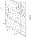
- Figure 1 presents a portion of a building surface 100.
- the building surface 100 may be of any appropriate type (e.g., a siding or roofing surface of a building) and may be defined in any appropriate manner (e.g., by a plurality of interconnected metal panels).
- the building surface 100 is in the form of a roofing surface 100.
- the roofing surface 100 has a pitch P (a slope or incline, the direction or orientation of which is indicated by the double-headed arrow in Figure 1 ).
- the arrow A identifies the direction of increasing slope (e.g., the "uphill” direction, the direction of increasing elevation along the roofing surface 100, or the up-slope direction).
- the arrow B identifies the direction of decreasing slope (e.g., the "downhill” direction, the direction of decreasing elevation along the roofing surface 100, or the down-slope direction).
- a plurality of photovoltaic modules 120 are positioned on the roofing surface 100 presented in Figure 1 .
- Each photovoltaic module 120 may be of any appropriate shape.
- each photovoltaic module 120 is rectangular and is installed in a landscape orientation (with the long dimension of each photovoltaic module 120 being disposed transversely to the pitch P of the roofing surface 100).
- the photovoltaic modules 120 could be installed in a portrait orientation on the roofing surface 100.
- the photovoltaic modules 120 will be installed in a plurality of rows and columns on the roofing surface 100.
- Each photovoltaic module 120 may be characterized as including a first perimeter section 124 (e.g., an upper edge or end of the photovoltaic module 120 when installed on the roofing surface 100), an oppositely disposed second perimeter section 130 (e.g., a lower edge or end of the photovoltaic module 120 when installed on the roofing surface 100), a third perimeter section 136 (e.g., a left edge or end of the photovoltaic module 120 when installed on the roofing surface 100), and an oppositely disposed fourth perimeter section 138 (e.g., a right edge or end of the photovoltaic module 120 when installed on the roofing surface 100).
- a frame may extend about the entire perimeter of each photovoltaic module 120.
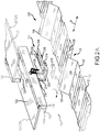
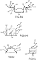
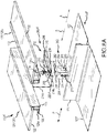
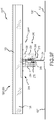
- FIG. 2A-L One embodiment of a photovoltaic assembly 150 that is installed on a building surface 100' is presented in Figures 2A-L .
- the building surface 100' is in the form of a roofing surface 100' having a pitch P, where again the arrow A identifies the up-slope direction and where the arrow B identifies the down-slope direction.
- the roofing surface 100' presented in Figures 2A-L is defined by a plurality of panels 102 that are appropriately interconnected (e.g., one edge or edge portion of one panel 102 may be disposed in overlapping/nesting relation with an adjacent panel 102 in the same row).
- Each panel 102 includes at least one rib 104, and may include one or more other structures such as one or more minor ribs 112 or the like.
- each panel 102 are disposed in at least substantially parallel relation and extend in the direction of the pitch P of the roofing surface 100' (e.g., the length dimension of each rib 104 may be disposed at the same pitch as the pitch P of the overall roofing surface 100').
- the ribs 104 of the panels 102 that collectively define the roofing surface 100' may be of any appropriate configuration.
- the ribs 104 are commonly referred to in the art as trapezoidal ribs 104.
- Other configurations may be appropriate.
- each rib 104 may be characterized as having an end section 106 (e.g., a flat surface; an uppermost portion of the rib 104 when defining the roofing surface 100').
- Two sidewalls 108 extend downwardly from the opposite sides of the end section 106 for each rib 104 (e.g., the two sidewalls 108 may be characterized as being spaced in a lateral dimension that is orthogonal to the pitch dimension, where the lateral and pitch dimensions are disposed within a common plane).
- the end section 106 and its two sidewalls 108 collectively define a hollow interior 110 for the corresponding rib 104.
- An interior angle e.g., measured within the hollow interior 110 of a given rib 104 between the end section 106 and each of the sidewalls 108 is greater than 90° (an obtuse angle) for the configuration of the ribs 104 presented in Figures 2A-L .
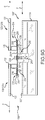
- the portion of the photovoltaic assembly 150 presented in Figures 2A-L includes a module bracket 200 and a corresponding pair of photovoltaic modules 120. It should be appreciated that the photovoltaic assembly 150 may include any appropriate number of photovoltaic modules 120 and any appropriate number of module brackets 200. Each module bracket 200 may include any appropriate number of wiring clips 236 (e.g., for supporting one or more wires used by the photovoltaic assembly 150). Each module bracket 200 may also be formed from any appropriate material or combination of materials (e.g., a metal or a metal alloy, and including from an electrically conductive material).
- a given module bracket 200 of the photovoltaic assembly 150 may engage a single photovoltaic module 120, or a given module bracket 200 could simultaneously engage two different photovoltaic modules 120 (e.g., adjacently disposed modules 120).
- the module bracket 200 includes a first mounting clip 202 (for engaging one photovoltaic module 120) and a separate second mounting clip 204 (for engaging a different photovoltaic module 120).
- the first mounting clip 202 and the second mounting clip 204 of a given module bracket 200 are spaced along the rib 104 on which the module bracket 200 is mounted (e.g., the first mounting clip 202 and the second mounting clip 204 are spaced along the pitch P of the roofing surface 100', with the first mounting clip 202 being disposed up-slope of its corresponding second mounting clip 204).
- Each of the mounting clips 202, 204 may be characterized as including a first section 206 and a second section 208 that is disposed above or in overlying relation to its corresponding first section 206.
- One end of each of the mounting clips 202, 204 is "open” and may be characterized as an inlet 212 to the corresponding mounting clip 202, 204.
- An opposite end of each of the mounting clips 202, 204 is "closed” and may be characterized as an end section 210.
- Each mounting clip 202, 204 may be characterized as being at least generally U-shaped or of a "money clip" configuration.
- each mounting clip 202, 204 may be in contact with its corresponding first section 206 prior to receiving a portion of a photovoltaic module 120 being installed on the corresponding mounting clip 202, 204.
- the spacing between the first section 206 of each mounting clip 202, 204 and its corresponding second section 208 increases when a corresponding portion of a photovoltaic module 120 is installed on the corresponding mounting clip 202, 204.
- This "expansion" of the mounting clips 202, 204 may be realized by a flexing or bending (e.g., an elastic deformation) of the corresponding mounting clip 202, 204, may be characterized as a deflection of the second section 208 at least generally away from its corresponding first section 206, or both.
- the end section 210 of each mounting clip 202, 204 may be characterized as a "living hinge” that allows relative movement between its corresponding first section 206 and second section 208.
- each mounting clip 202, 204 may be characterized as being an arcuately-shaped, pliable section that is located between its corresponding first section 206 and second section 208, and that allows for a desired relative movement between its corresponding first section 206 and corresponding second section 208 (e.g., that allows the second section 208 of a given mounting clip 202, 204 to at least generally pivot away from and back toward its corresponding first section 206).
- At least part of the second section 208 of each mounting clip 202, 204 may at least at some point in time be biased toward its corresponding first section 206.
- This biasing force may be provided by the end section 210 of the corresponding mounting clip 202, 204 (e.g., an elastic configuration).
- the amount of the biasing force may progressively increase (e.g., by an elastic "flexing" of the corresponding end section 210).
- a biasing force could be exerted on the second section 208 when engaged with its corresponding first section 206, such is not required.
- Each mounting clip 202, 204 of each module bracket 200 may mechanically engage and support a photovoltaic module 120 on the roofing surface 100'.
- the mounting clips 202, 204 may also be used to establish an electrical connection with a corresponding photovoltaic module 120.
- the surface of the second section 208 that faces or projects toward its corresponding first section 206 may include one or more projections 218 (e.g., having one or more "sharp" edges; an electrical contact).
- the module 120 When a photovoltaic module 120 is installed in a given mounting clip 202, 204, the module 120 may be characterized as being "bonded” or electrically bonded to the corresponding mounting clip 202, 204 (or more generally as being bonded to the module bracket 200) via these projections 218.
- a string or collection of photovoltaic modules 120 may therefore be electrically connected (e.g., disposed at a common electrical potential) via the associated module brackets 200 (e.g., an electrical path may include the frames of the various photovoltaic modules 120 in the string, along with the corresponding module brackets 200 that engage these frames).
- This electrical path may be used to ground the string or collection of photovoltaic modules 120 (e.g., by running a single grounding wire from the frame of one of the photovoltaic modules 120 in the string to ground, as each adjacent pair of modules 120 in the string may be electrically interconnected by a shared module bracket 200).
- each electrical contact 218 is preferably of the same configuration, only one will be described.
- the electrical contact 218 cantilevers from a remainder of the second section 208 of the corresponding mounting clip 202, 204 (e.g., each electrical contact 218 may be "punched” from the second section 208). That is, the electrical contact 218 is partially separated from its corresponding second section 208 to define an aperture 218a in the second section 208.
- the boundary between the electrical contact 218 and the remainder of the second section 208 (where the electrical contact 218 remains attached to its corresponding second section 208) is identified by reference numeral 218b in Figure 2J .
- the electrical contact 218 may flex or bend relative to its corresponding second section 208 at least generally about this boundary 218b, and as such this may also be referred to as "hinge 218b.”
- the electrical contact 218 is at least generally triangularly-shaped, and in any case extends downwardly toward its corresponding first section 206 at an angle. Other configurations may be appropriate.
- a free end section or point 218c of the electrical contact 218 may be characterized as being disposed in the direction of the closed end section 210 of the corresponding mounting clip 202, 204, while the hinge 218b may be characterized as being disposed in the direction of the inlet 212 to the corresponding mounting clip 202, 204. That is, the electrical contact 218 may be characterized as extending from its hinge 218b with the second section 208, at least generally in the direction of the closed end section 210 of the corresponding mounting clip 202, 204.
- the electrical contact 218 may also be characterized as extending from its hinge 218b with the second section 208, at least generally in the direction of its corresponding first section 206.
- first mounting clip 202 and the second mounting clip 204 are spaced along the pitch P of the roofing surface 100', with the first mounting clip 202 being disposed up-slope of its corresponding second mounting clip 204 (in the up-slope direction A).
- the mounting clips 202, 204 are oriented such that the inlet 212 of the first mounting clip 202 at least generally projects toward or faces in the direction of the second mounting clip 204, and such that the inlet 212 of the second mounting clip 204 at least generally projects toward or faces in the direction of the first mounting clip 202 (e.g., the inlet 212 to the first mounting clip 202 may project in the down-slope direction B; the inlet 212 to the second mounting clip 204 may project in the up-slope direction A).
- the mounting clips 202, 204 are oriented such that the end section 210 of the first mounting clip 202 is disposed up-slope of the inlet 212 of the first mounting clip 202, and such that the end section 210 of the second mounting clip 204 is disposed down-slope of the inlet 212 of the second mounting clip 204.
- the mounting clips 202, 204 are oriented such that the inlet 212 of the second mounting clip 204 is disposed up-slope of the end section 210 of the second mounting clip 204, such that the inlet 212 of the first mounting clip 202 is disposed up-slope of the inlet 212 of the second mounting clip 204, and such that the end section 210 of the first mounting clip 202 is disposed up-slope of the inlet 212 of the first mounting clip 202.
- a base section 220 of the module bracket 200 is disposed between the first mounting clip 202 and the second mounting clip 204 along the pitch P of the roofing surface 100 when the module bracket 200 is installed thereon.
- the base section 220 may be characterized as being an at least generally flat or planar structure.
- the mounting clips 202, 204 of the module bracket 200 are offset from the base section 220.
- one riser section 214 extends from base section 220 (e.g., one end thereof) to the first mounting clip 202.
- Another riser section 214 extends from the base section 220 (e.g., an opposite end thereof) to the second mounting clip 204.
- the riser sections 214 may be at least generally parallel to one another, and may be oriented at least generally perpendicularly to the base section 220.
- At least one wiring clip 236 may be disposed on the "underside" of the first mounting clip 202 (e.g., disposed within the space between the first mounting clip 202 and the rib 104 (e.g., its end section 106) on which the module bracket 200 is mounted).
- at least one wiring clip 236 may be disposed on the "underside” of the second mounting clip 204 (e.g., disposed within the space between the second mounting clip 204 and the rib 104 (e.g., its end section 106) on which the module bracket 200 is mounted).
- the two riser sections 214 of the module bracket 200 are of a common height or length.
- the first mounting clip 202 and the second mounting clip 204 of the module bracket 200 are disposed at a common elevation relative to the base section 220.
- the first mounting clip 202 and the second mounting clip 204 may be characterized as being at least generally coplanar with each other in a dimension that is parallel with the pitch P of the roofing surface 100'.
- first mounting clip 202 and the second mounting clip 204 may be characterized as being disposed at a common, higher elevation than the base section 220, measured relative to a reference plane that contains the flat, base sections of the panel 102 (and from which the ribs 104 may extend).
- the base section 220 of the module bracket 200 may be seated on the end section 106 of one of the ribs 104 of the roofing surface 100'.
- the surface of the base section 220 that that interfaces with or at least projects toward an end section 106, when the module bracket 200 is installed on the corresponding rib 104, may include a pair of stiffening beads or stiffeners 226. These stiffeners 226 may enhance the structural integrity of the module bracket 200, and may also extend along the riser sections 214 and the first sections 206 of the mounting clips 202, 204.
- the convex or protruding configuration/shape of the stiffeners 226 on the lower surface of the base section 220 may also function to reduce the potential for over-compressing a gasket 216 that may be positioned between the base section 220 and the end section 106 of the rib 104 on which the module bracket 200 is being installed.
- One or more panel fasteners 238 may be used to secure the module bracket 200 to a rib 104 of the roofing surface 100'.
- two panel fasteners 238 e.g., threaded screws
- the base section 220 of the module bracket 200 may include one or more fastener apertures 228, each of which may accommodate a single panel fastener 238.
- Each module bracket 200 accommodates a maximum of two photovoltaic modules 120. Portions of two photovoltaic modules are illustrated in Figure 2A and 2L - one of the modules 120 is further identified by reference numeral 120a, and the other is further identified by reference numeral 120b.
- Each photovoltaic module 120 may be characterized as having a photovoltaic cell or body 122.
- a first frame section 126 may define the first perimeter section 124 of the corresponding photovoltaic module 120.
- a second frame section 132 may define the second perimeter section 130 of the corresponding photovoltaic module 120.
- the third perimeter section 136 ( Figure 1 ) of a photovoltaic module 120 could be defined by a frame section of any appropriate configuration (e.g., to protect the corresponding edge of the PV body 122), as could the fourth perimeter section 138 ( Figure 1 ) of a photovoltaic module 120.
- the first frame section 126 of the photovoltaic module 120 e.g., an uphill end or edge of the photovoltaic module 120 when installed on the roofing surface 100'
- the second frame section 132 of the photovoltaic module 120 may include a second module flange 134 that cantilevers or extends at least generally in the direction of the first frame section 126 of the photovoltaic module 120 (e.g., an uphill end or edge of the photovoltaic module 120 when installed on the roofing surface 100').
- the first module flange 128 may be characterized as extending at least generally in the direction of the second module flange 134, and vice versa.
- the first module flange 128 may be characterized as extending in the down-slope direction B when the photovoltaic module 120 is installed on the roofing surface 100' (and terminates at free end 128a that is spaced from a free end 134a of the second module flange 134 for this same module 120).
- the second module flange 134 may be characterized as extending in the up-slope direction A when the photovoltaic module 120 is installed on the roofing surface 100' (and terminates at a free end 134a that is spaced from a free end 128a of the first module flange 128 for this same module 120).
- the module bracket 200 provides what may be characterized as a "slide fit" for each photovoltaic module 120 installed thereon.
- An embodiment of an installation method that utilizes this "slide fit" connection will be discussed in more detail below.
- the second module flange 134 of the photovoltaic module 120a may be slid relative to the first mounting clip 202. This will initially direct the free end 134a of the second module flange 134 of the photovoltaic module 120a into the inlet 212 of the first mounting clip 202.
- Further relative movement between the photovoltaic module 120a and the first mounting clip 202 may move its second section 208 at least generally away from its first section 206 (e.g., by a flexing of the end section 210 of the first mounting clip 202; by the second section 208 at least generally moving or pivoting away from its corresponding first section 206).
- the free end 134a of the second module flange 134 may come into contact the end section 210 of the first mounting clip 202 to "positionally register" the photovoltaic module 120a relative to the module bracket 200.
- an electrical path may be provided between the module bracket 200 and the photovoltaic module 120a by the second module flange 134 of the module 120a being sandwiched between the second section 208 and the corresponding first section 206 of the first mounting clip 202, where the projections 218 on the second section 208 may facilitate the establishment of electrical contact with the second module flange 134 of the module 120a.
- the photovoltaic module 120b may be installed on the second mounting clip 206 in the same general manner as the photovoltaic module 120a. Generally, the first module flange 128 of the photovoltaic module 120b may be slid relative to the second mounting clip 204. This will initially direct the free end 128a of the first module flange 128 of the photovoltaic module 120b into the inlet 212 of the second mounting clip 204.
- an electrical path may be provided between the module bracket 200 and the photovoltaic module 120b by the first module flange 128 of the module 120b being sandwiched between the second section 208 and the corresponding first section 206 of the second mounting clip 204, where the projections 218 on the second section 208 may facilitate the establishment of electrical contact with the first module flange 128 of the module 120b.
- a number of observations may be made with regard to the module bracket 200 in relation to installing photovoltaic modules on the roofing surface 100' (and that are equally applicable to the module brackets 200 i , 200 iii , 200 v , and 200 vi discussed below).
- contact between the module bracket 200 and the photovoltaic modules 120a, 120b is limited to the mounting clips 202, 204 - no other portion of the module bracket 200 contacts either the photovoltaic module 120a or the photovoltaic module 120b.
- Another is that the entirety of the retention forces exerted by the module bracket 200 on the photovoltaic modules 120a, 120b is provided by the mounting clips 202, 204 (no other forces are used to retain the modules 120a, 120b on the module bracket 200).
- the mounting clip 202 may exert a compressive force on the second module flange 134 of the photovoltaic module 120a.
- the mounting clip 204 may exert a compressive force on the first module flange 128 of the photovoltaic module 120b.
- the riser sections 214 of the module bracket 200 provide a vertical offset between the base section 220 and each of the mounting clips 202, 204, as noted. This increases the spacing between the photovoltaic modules 120a, 120b and the underlying roofing surface 100'.
- One advantage of this increased spacing between the photovoltaic modules 120a, 120b and the underlying roofing surface 100' is an enhanced cooling of the photovoltaic modules 120a, 120b, which may increase their operational efficiency (e.g., by accommodating an increased airflow between the roofing surface 100' and the underside of the photovoltaic modules 120a, 120b).
- the vertical offset between the base section 220 and each of the mounting clips 202, 204 is at least about 0.5" in one embodiment, and is at least about 0.75" in another embodiment (e.g., measured orthogonally to the pitch P of the roofing surface 100' when the module bracket 200 is installed on the roofing surface 100').
- the module bracket 200 itself provides an electrical connection between the photovoltaic module 120a and the photovoltaic module 120b - the module bracket 200 provides an electrical path between the modules 120a and 120b.
- At least one electrical contact 218 is incorporated by each of the mounting clips 202, 204.
- each electrical contact 218 is incorporated by the second section 208 on each of the mounting clips 202, 204.
- each such electrical contact 218 may scratch the surface of the second module flange 134 of the photovoltaic module 120a to enhance the electrical connectivity between the mounting clip 202 and the photovoltaic module 120a.
- at least one (and preferably multiple) electrical contacts 218 should engage the first module flange 128.
- the free end section 218c of each such electrical contact 218 may scratch the surface of the first module flange 128 of the photovoltaic module 120b to enhance the electrical connectivity between the mounting clip 204 and the photovoltaic module 120b.
- sliding the module flanges 134, 128 into the mounting clips 202, 204, respectively, may cause one or more of the electrical contacts 218 to move relative to the remainder of its corresponding second section 208 (of the corresponding mounting clip 202, 204) - the free end section 218c of one or more electrical contacts 218 may move at least generally away from the corresponding module flange 128, 134 (and at least generally about its corresponding hinge 218b). However, the free end section 218c of each electrical contact 218 should remain in contact with the corresponding module flange 128, 134.
- contact between the second section 208 of each mounting clip 202, 204 and the corresponding module flange 128, 134 may be limited to one or more electrical contacts 218 (e.g., it may be that the only portion of a given second section 208 to contact a given module flange 128, 134 is one or more of its electrical contacts 218).
- each electrical contact 218 may also provide resistance to sliding the photovoltaic modules 120a, 120b out of the mounting clips 202, 204, respectively. Sliding the photovoltaic module 120a relative to the mounting clip 202 in a direction to withdraw the second module flange 134 out through the inlet 212 of the mounting clip 202 may cause one or more electrical contacts 218 to move relative to the remainder of its corresponding second section 208 of the mounting clip 202 - the free end section 218c of one or more electrical contacts 218 may move at least generally toward the second module flange 134 of the photovoltaic module 120a (and at least generally about its corresponding hinge 218b in a direction that is opposite of the direction that such a free end section 218c may move during installation; a "wedging action" for one or more electrical contacts 218).
- sliding the photovoltaic module 120b relative to the mounting clip 204 in a direction to withdraw the first module flange 128 out through the inlet 212 of the mounting clip 204 may cause one or more electrical contacts 218 to move relative to the remainder of its corresponding second section 208 of the mounting clip 204 - the free end section 218c of one or more electrical contacts 218 may move at least generally toward the first module flange 128 of the photovoltaic module 120b (and at least generally about its corresponding hinge 218b in a direction that is opposite of the direction that such a free end section 218c may move during installation; a "wedging action" for one or more electrical contacts 218).
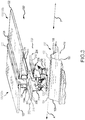
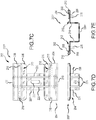
- Figure 3 present another embodiment of a photovoltaic assembly 150 i that utilizes a variation of the module bracket 200 discussed above in relation to Figures 2A-L .
- Those portions of the module bracket 200 i of Figure 3 that differ from the module bracket 200 of Figures 2A-L are identified by a superscripted "i". Unless otherwise noted, the discussion presented above with regard to the module bracket 200 is applicable to the module bracket 200 i .
- the module bracket 200 i of Figure 3 attaches to the rib 104 of the roofing surface 100' in a different manner than the module bracket 200 of Figures 2A-L .
- the module bracket 200 i utilizes a pair of bracket flanges 230 that extend from opposite sides of the base section 220 i of the module bracket 200 i .
- One of the bracket flanges 230 may be positioned alongside at least an upper portion of one of the sidewalls 108 of the rib 104 on which the module bracket 200 i is being installed, while the other of the bracket flanges 230 may be positioned alongside at least an upper portion of the other of the sidewalls 108 of this same rib 104.
- a gasket 216 i may be positioned between one of the bracket flanges 230 and its corresponding sidewall 108 of the rib 104, while another gasket 216 i may be positioned between the other of the bracket flanges 230 and its corresponding sidewall 108 of the rib 104.
- Each bracket flange 230 may include one or more fastener apertures 232 (two in the illustrated embodiment).
- At least one panel fastener 238 may be directed through one of the bracket flanges 230 (e.g., through a corresponding fastener aperture 232), through any corresponding gasket 216 i , through a corresponding portion of the sidewall 108 of the rib 104, and may terminate within the hollow interior 110 of the rib 104.
- At least one panel fastener 238 may be directed through the other of the bracket flanges 230 (e.g., through a corresponding fastener aperture 232), through any corresponding gasket 216 i , through a corresponding portion of the sidewall 108 of the rib 104, and may terminate within the hollow interior 110 of the rib 104.
- the base section 220 i of the module bracket 200 i need not include any fastener apertures 232 for the Figure 3 embodiment.
- the base section 200 i could also thereby incorporate one or more wiring clips 236.
- the module bracket 200 i could be fabricated in any appropriate manner.
- the mounting clips 202, 204, the riser sections 214, and the base section 220 i could be of a one-piece construction (e.g., integrally formed from a piece of sheet metal).
- Each of the bracket flanges 230 could be separately formed and separately attached to the opposing sides of the base section 220 i in any appropriate manner.
- the module bracket 200 i could utilize the stiffeners 226 discussed above in relation to the module bracket 200.
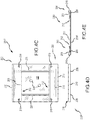
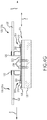
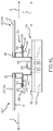
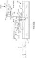
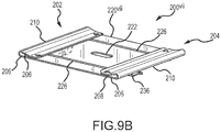
- FIGs 4A-G present another embodiment of a photovoltaic assembly 150" that utilizes a variation of the module bracket 200 discussed above in relation to Figures 2A-L .
- Those portions of the module bracket 200" of Figures 4A-G that differ from the module bracket 200 of Figures 2A-L are identified by a superscripted "ii”. Unless otherwise noted, the discussion presented above with regard to the module bracket 200 is applicable to the module bracket 200".
- the module bracket 200" of Figures 4A-G eliminates the two riser sections 214 used by the module bracket 200 of Figures 2A-L .
- the base section 220 of the module bracket 200" is at least generally coplanar with the first section 206 of each of the mounting clips 202, 204.
- the gasket 216" may be of an extended length so as to be disposed between the upper section 106 of the rib 104 and each of the first mounting clip 202, the base section 220, and the second mounting clip 204.
- a pair of bracket flanges 230 could extend from the opposite sides of the base section 220, and could be used to attach the module bracket 200" to the rib 104 of the roofing surface 100' in the manner of the Figure 3 embodiment addressed above.
- a pair of bracket flanges 230 could extend from the opposite sides of the base section 220, but the module bracket 200 iii could still be attached to the rib 104 of the roofing surface 100' in the manner illustrated in Figures 4A-G (e.g., not using any panel fasteners 238 in conjunction with the bracket flanges 230).
- the module bracket 200" in relation to installing photovoltaic modules on the roofing surface 100'.
- the mounting clips 202, 204 are not offset from the base section 220 in the case of the module bracket 200"
- the module bracket 200" does not provide the spacing that is provided by the embodiment of Figures 2A-L and the associated benefits.
- the entirety of the retention forces exerted by the module bracket 200" on the photovoltaic modules 120a, 120b continues to be provided by the mounting clips 202, 204 (no other forces are used to retain the modules 120a, 120b on the module bracket 200").
- the mounting clip 202 may exert a compressive force on the second module flange 134 of the photovoltaic module 120a.
- the mounting clip 204 may exert a compressive force on the first module flange 128 of the photovoltaic module 120b.
- the module bracket 200" also includes at least one least one electrical contact 218 for each of the mounting clips 202, 204, the corresponding discussion presented above with regard to the embodiment of Figures 2A-L is equally applicable to the embodiment of Figures 4A-G .
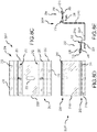
- Figure 5 presents another embodiment of a photovoltaic assembly 150 iii that utilizes a variation of the module bracket 200 i discussed above in relation to Figure 3 .
- Those portions of the module bracket 200 iii of Figure 5 that differ from the module bracket 200 i of Figure 3 are identified by a superscripted "iii".
- the discussion presented above with regard to the module brackets 200 and 200 i is applicable to the module bracket 200 iii .
- the module bracket 200 iii of Figure 5 is configured to dispose the mounting clips 202, 204 at different elevations from the roofing surface 100' (e.g., the mounting clips 202, 204 are spaced a different distance from a reference plane that at least generally contains the end section 106 of the ribs 104 for the roofing surface 100').
- the two riser sections 214a, 214b are of different lengths in the case of the module bracket 200 iii (the riser sections 214a, 214b may continue to be at least generally parallel to one another, and may continue to be at least generally perpendicular to the base section 220 i ).
- the riser section 214a that extends between the base section 220 i and the first mounting clip 202 is shorter than the riser section 214b that extends between the base section 220 i and the second mounting clip 204, although this could be reversed. That is and for the illustrated embodiment, the second mounting clip 204 is disposed at a higher elevation than the first mounting clip 202 (measured relative to a reference plane that contains the end sections 106 of the ribs 104 for the roofing surface 100').
- This may be used to dispose the photovoltaic modules 120a, 120b engaged by the module bracket 200 iii at an angle relative to the roofing surface 100' (e.g., so the modules 120a, 120b are disposed in non-parallel relation to the roofing surface 100').
- this mounting clip 202, 204 is still offset from the base section 220 i by a distance of at least about 0.5" in one embodiment, and by a distance of at least about 0.75" in another embodiment.
- each of the mounting clips 202, 204 may be offset from the base section 220 i by a distance of at least about 0.5" in one embodiment, and by a distance of at least about 0.75" in another embodiment, to provide the enhanced spacing advantages discussed above with regard to the embodiment of Figures 2A-L .
- the module bracket 200 iii could utilize the stiffeners 226 discussed above in relation to the module bracket 200.
- the bracket flanges 230 could be eliminated and the module bracket 200 iii could be attached to the rib 104 of the roofing surface 100' in the manner of the embodiment of Figures 2A-L .
- the bracket flanges 230 could be retained, but the module bracket 200 iii could be attached to the rib 104 of the roofing surface 100' in the manner of the embodiment of Figures 2A-L (e.g., not using any panel fasteners 238 in conjunction with the bracket flanges 230).
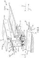
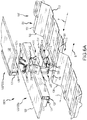
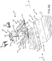
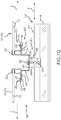
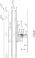
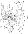
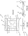
- FIGS 6A-L present another embodiment of a photovoltaic assembly 150 iv that may utilize the same module bracket 200 discussed above in relation to Figures 2A-L , but a different manner of maintaining the module bracket 200 is a fixed position relative to the roofing surface 100'.
- a separate panel bracket 240 is positioned over the module bracket 200 when positioned on a rib 104 of the roofing surface 100', and the panel bracket 240 is instead anchored to this rib 104.
- the module bracket 200 in the embodiment of Figures 6A-L could eliminate the fastener apertures 228 that extend through the base section 220, as they are not utilized in this configuration.
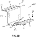
- the panel bracket 240 could also be used with the module bracket 200" discussed above in relation to Figures 4A-G , as well as with the module bracket 200 vi that will be discussed below in relation the Figures 8A-G (but for installations on the roofing surface 100', versus the roofing surface 100" shown in Figures 8A-G ).
- the panel bracket 240 used by the photovoltaic assembly 150 iv of Figures 6A-L includes a cap section 242 and a pair of bracket flanges 230 iv at least generally of the type used in the Figure 3 embodiment discussed above. As the bracket flanges 230 iv do not extend from the base section 220, the bracket flanges 230 iv in Figures 6A-L are further identified by a superscripted "iv".
- a separate transition section 234 may interconnect the cap section 242 with the corresponding bracket flange 230 iv . Each transition section 234 may be at least generally s-shaped.
- the panel bracket 240 used by the photovoltaic assembly 150 iv of Figures 6A-L may be fabricated in any appropriate manner.
- the panel bracket 240 could be of a one-piece construction (e.g., having the cap section 242 (which may include a wiring clip 236) and the two bracket flanges 230 iv being integrally formed from a piece of sheet metal).
- each of the bracket flanges 230 iv could be separately formed and separately attached to the opposing sides of the cap section 242 in any appropriate manner.
- the module bracket 200 may be positioned on the upper section 106 of one of the ribs 104 for the roofing surface 100'.
- the panel bracket 240 may then be positioned over the module bracket 200, such that the base section 220 of the module bracket 200 is disposed (e.g., sandwiched) between the cap section 242 of the panel bracket 240 and the end section 106 of one of the ribs 104.
- One of the bracket flanges 230 iv will then be positioned alongside at least an upper portion of one of the sidewalls 108 of the rib 104, while the other of the bracket flanges 230 iv will be positioned alongside at least an upper portion of the other of the sidewalls 108 of this same rib 104.
- a gasket 216 i may be positioned between one of the bracket flanges 230 iv and its corresponding sidewall 108 of the rib 104, while another gasket 216 i may be positioned between the other of the bracket flanges 230 iv and its corresponding sidewall 108 of the rib 104.
- Each bracket flange 230 iv may include one or more fastener apertures 232 (two in the illustrated embodiment). At least one panel fastener 238 (two in the illustrated embodiment) may be directed through one of the bracket flanges 230 iv (e.g., through a corresponding fastener aperture 232), through any corresponding gasket 216 i , through a corresponding portion of the sidewall 108 of the rib 104, and may terminate within the hollow interior 110 of the rib 104.
- At least one panel fastener 238 may be directed through the other of the bracket flanges 230 iv (e.g., through a corresponding fastener aperture 232), through any corresponding gasket 216 i , through a corresponding portion of the sidewall 108 of the rib 104, and may terminate within the hollow interior 110 of the rib 104.
- the base section 220 of the module bracket 200 need not include any fastener apertures 232.
- FIGs 7A-G present another embodiment of a photovoltaic assembly 150 v that may utilize a module bracket similar to that used by the embodiment of Figures 2A-L , but which has been adapted for use with another type of roofing surface.
- the roofing surface 100" associated with the photovoltaic assembly 150 v is defined by a plurality of panels 102" that are appropriately interconnected (e.g., one edge or edge portion of one panel 102" may be "nested” or interlocked with an adjacent panel 102" in the same row).
- Each adjacent pair of panels 102" of the roofing surface 100" is interconnected in a manner so as to define a standing seam 114.
- a base may be disposed between the opposing edges of each panel 102". The entirety of this base may be flat or planar.
- one or more small structures may be formed/shaped into the base of one or more panels 102" of the building surface 100", for instance one or more crests, minor ribs, intermediate ribs, pencil ribs, striations, fluting, flutes, or the like.
- the module brackets 200 v used by the photovoltaic assembly 150 v of Figures 7A-G are not directly attached to the roofing surface 100", in contrast to the embodiments of Figures 2A-6L . Instead, a mounting device 260 is attached to a standing seam 114 of the roofing surface 100", and the module bracket 200 v is attached to this mounting device 260.
- the mounting device 260 includes an upper surface 262, an oppositely disposed lower or bottom surface 266, a pair of oppositely disposed side surfaces 264, and a pair of oppositely disposed ends 268.
- a slot 270 extends between the two ends 268 of the mounting device 260. At least an upper portion of a standing seam 114 may be received in this slot 270.
- At least one threaded hole 278 extends from one of the side surfaces 264 to the slot 270. Multiple threaded holes 278 (that extend to the slot 270) could be provided on a given side surface 264.
- At least one threaded hole 278 could extend from one of the side surfaces 264 of the mounting device 260 to the slot 270, and at least one threaded hole 278 could extend from the other of the side surfaces 264 of this mounting device 260 to the slot 270.
- at least one seam fastener 245 may be threadably engaged with the mounting device 260 (e.g., via a corresponding threaded hole 278), and may extend into the slot 270 to engage a standing seam 114 disposed therein.
- the end of each seam fastener 245 that engages a standing seam 114 disposed in the slot 270 may be configured so as to not penetrate or puncture the roofing surface 100" (e.g., having a rounded or convexly-shaped end).
- one or more seam fasteners 245 may be used to attach the mounting device 260 to the roofing surface 100" (more specifically, to attach the mounting device 260 to one of the standing seams 114 of the roofing surface 100").
- the standing seam 114 of the building surface 100" is commonly referred to as a vertical standing seam configuration.
- the upper surface 262 of the mounting device 260 may include at least one flat section for interfacing with the module bracket 200 v (more specifically, the base section 220 v of the module bracket 200 v ). This upper surface 262 may also include a threaded hole 276 for interconnecting the module bracket 200 v with the mounting device 260 when installed on the vertical standing seam 114.
- the mounting device 260 may also be used to install the module bracket 200 v on what is commonly referred to as a horizontal standing seam configuration (e.g., where an end section of the standing seam may be disposed at least generally parallel with the pitch of the roofing surface).
- At least one of the side surfaces 264 of the mounting device 260 may include at least one flat section and at least one threaded hole 276.
- the base section 220 v of the module bracket 220 v would be disposed on such a side surface 264 of the mounting device 260.
- a threaded fastener 250 e.g., a bolt
- a threaded fastener 250 may be directed through an elongated slot 222 on the base section 220 v of the module bracket 200 v , and may be threaded onto the mounting device 260 via a threaded hole 276. Any appropriate aperture may extend through the base section 220 v of the module bracket 200 v .
- the elongated slot 222 in the illustrated embodiment provides for at least some level of adjustment of the relative position between the module bracket 200 v and the mounting device 260 prior to disposing the threaded fastener 250 in a position that clamps the module bracket 200 v onto the mounting device 260.
- the mounting clips 202, 204 will now be disposed in spaced relation to the roofing surface 100" (e.g., above or in overlying relation to the standing seam 114 to which the module bracket 200 v is interconnected via a mounting device 260).
- FIGs 8A-G present another embodiment of a photovoltaic assembly 150 vi .
- the photovoltaic assembly 150 vi adapts the module bracket 200 iii from the embodiment of Figure 5 for use with the roofing surface 100" from the embodiment of Figures 7A-G .
- the base section 220 vi of the module bracket 200 vi includes an elongated aperture 222 of the type discussed above in relation to the embodiment of Figures 7A-G .
- the module bracket 200 vi presented in Figures 8A-G does not show a pair of stiffening beads or stiffeners 226, the superscripted "vi" notation is used for its base section 220 vi (although stiffeners 226 could be used by the module bracket 200 vi ).
- the module bracket 200 vi for the photovoltaic assembly 150 vi may be installed on a standing seam 114 in accordance with the discussion of Figures 7A-G .
- the discussion presented above with regarding to the embodiment of Figure 5 is applicable to the embodiment of Figures 8A-G (and vice versa).
- this mounting clip 202, 204 is still offset from the base section 220 vi by a distance of at least about 0.5" in one embodiment, and by a distance of at least about 0.75" in one embodiment.
- each of the mounting clips 202, 204 may be offset from the base section 220 vi by a distance of at least about 0.5" in one embodiment, and by a distance of at least about 0.75" in another embodiment, to provide the enhanced spacing advantages discussed above with regard to the embodiment of Figures 2A-L .
- Figures 9A-G present another embodiment of a photovoltaic assembly 150 vii .
- the photovoltaic assembly 150 vii adapts the module bracket 200" from the embodiment of Figures 4A-G for use with the roofing surface 100" from the embodiment of Figures 7A-G .
- the base section 220 vii of the module bracket 200 vii includes an elongated aperture 222 of the type discussed above in relation to the embodiment of Figures 7A-G .
- the module bracket 200 vii for the photovoltaic assembly 150 vii may be installed on a standing seam in accordance with the discussion of Figures 7A-G .
- the module bracket 200 vii in relation to installing photovoltaic modules on the roofing surface 100".
- the mounting clips 202, 204 are not offset from the base section 220 in the case of the module bracket 200 vii , the module bracket 200 vii does not provide the spacing provided by the embodiment of Figures 2A-L (although the use of the mounting device 260 does provide some level of enhanced spacing for the embodiment of Figures 9A-G ).
- the entirety of the retention forces exerted by the module bracket 200v ii on the photovoltaic modules 120a, 120b continues to be provided by the mounting clips 202, 204 (no other forces are used to retain the modules 120a, 120b on the module bracket 200 vii ).
- the mounting clip 202 may exert a compressive force on the second module flange 134 of the photovoltaic module 120a.
- the mounting clip 204 may exert a compressive force on the first module flange 128 of the photovoltaic module 120b.
- the module bracket 200 vii also includes at least one least one electrical contact 218 for each of the mounting clips 202, 204, the corresponding discussion presented above with regard to the embodiment of Figures 2A-L is equally applicable to the embodiment of Figures 9A-G .
- a plurality of first module brackets 200 may be installed in the above-noted manner on the roofing surface 100'.
- the first mounting clip 202 of each module bracket 200 is installed on the building surface 100' in the up-slope direction A from its corresponding second mounting clip 204.
- the noted first module brackets 200 may be installed in a first row on the roofing surface 100', where this first row extends at least generally transverse to the pitch P of the roofing surface 100' (e.g., "across" the roofing surface 100'; along a line that is disposed at a common elevation on the roofing surface 100'). Any appropriate spacing may be utilized between adjacent pairs of first module brackets 200.
- At least one second module bracket 200 may be installed on the second module flange 134 of the photovoltaic module 120a. More specifically, the first mounting clip 202 of each second module bracket 200 being installed on the photovoltaic module 120a may be slid onto the second module flange 134 of the photovoltaic module 120a (e.g., the second module flange 134 may be directed/slid between the first section 206 and its corresponding second section 208 of the first mounting clip 202 for each second module bracket 200 being installed on the photovoltaic module 120a).
- the photovoltaic module 120a may be installed on at least one of the first module brackets 200 in the first row (typically at least two of the first module brackets 200 in the first row, and again that have been previously anchored relative to the roofing surface 100'). Initially, the first module flange 128 of the photovoltaic module 120a may be positioned in the space between the first mounting clip 202 and the second mounting clip 204 of at least one of the first module brackets 200 in the first row.
- the first module flange 128 of the photovoltaic module 120a may be moved in the down-slope direction B to slide into the second mounting clip 204 of at least one of the first module brackets 200 in the first row (e.g., the first module flange 128 may be directed/slid between the first section 206 and its corresponding second section 208 of the second mounting clip 204 for each first module bracket 200 being used to install the photovoltaic module 120a on the roofing surface 100').
- the first module flange 128 of the photovoltaic module 120a may be simultaneously slid into the second mounting clip 204 of two or more of the first module brackets 200 in the first row.
- movement of the photovoltaic module 120a in the down-slope direction B may be terminated by the free end 128a of first module flange 128 of the photovoltaic module 120a engaging the end section 210 of the second mounting clip 204 for one or more of the first module brackets 200 in the first row.
- each second module bracket 200 (that was previously installed on the second module flange 134 of the photovoltaic module 120a) may be repositioned along this second module flange 134 (by sliding any given second module bracket 200 along the length dimension of the second module flange 134 for the photovoltaic module 120a) to align such a second module bracket 200 with the desired rib 104 of the roofing surface 100' (if required).
- Each second module bracket 200 on the second module flange 134 of the photovoltaic module 120a may also be slid in the down-slope direction B until the free end 134a of this second module flange 134 engages the end section 210 of its first mounting clip 202.
- each of the second module brackets 200 on the second module flange 134a of the photovoltaic module 120a may be attached to the roofing surface 100' in the above-noted matter.
- These second module brackets 200 may extend in a second row on the roofing surface 100', where this second row extends at least generally transverse to the pitch P of the roofing surface 100' (e.g., "across" the roofing surface 100'; along a line that is disposed at a common elevation on the roofing surface 100'), and where this second row for the second module brackets 200 is at least generally parallel with the noted first row for the first module brackets 200.
- a variation of the foregoing would be to install the first mounting clip 202 of one or more of the second module brackets 200 on the second module flange 134 of the photovoltaic module 120 after installing the first module flange 128 of the photovoltaic module 120 on one or more of the first module brackets 200 (again, that have already been attached to the roofing surface 100'), and thereafter anchor each such second module bracket 200 (on the second module flange 134 of the photovoltaic module 120a) relative to the roofing surface 100'.
- the photovoltaic module 120b may be installed on at least one of the second module brackets 200 in the second row (typically at least two of the second module brackets 200 in the second row).
- the first module flange 128 of the photovoltaic module 120b may be positioned in the space between the first mounting clip 202 and the second mounting clip 204 of at least one of the second module brackets 200 in the second row. Thereafter, the first module flange 128 of the photovoltaic module 120b may be moved in the down-slope direction B to slide into the second mounting clip 204 of at least one of the second module brackets 200 in the second row (e.g., the first module flange 128 may be directed/slid between the first section 206 and its corresponding second section 208 of the second mounting clip 204 for each second module bracket 200 being used to install the photovoltaic module 120b on the roofing surface 100').
- the first module flange 128 may be simultaneously slid into the second mounting clip 204 of two or more of the second module brackets 200 in the second row. Movement of the photovoltaic module 120b in the down-slope direction B may be terminated by the free end 128a of first module flange 128 of the photovoltaic module 120b engaging the end section 210 of the second mounting clip 204 for one or more of the second module brackets 200 in the second row.
- One or more third module brackets 200 may be installed on the second module flange 134 of the second photovoltaic module 120b in the manner discussed above regarding the second module brackets 200 and the second module flange 134 of the first photovoltaic module 120a, and may then be anchored relative to the roofing surface 100' to complete the installation of the photovoltaic module 120b (e.g., to dispose such third module brackets 200 in a third row that is at least generally parallel to the noted first row for the first module brackets 200).
Claims (19)
- Ensemble photovoltaïque, comprenant :une surface de toiture (100'), dans lequel ladite surface de toiture (100') comprend une nervure creuse (104), dans lequel ladite nervure creuse (104) comprend une section d'extrémité (106) qui définit une partie la plus haute de ladite nervure creuse (104), et dans lequel ladite nervure creuse (104) comprend en outre des première et seconde parois latérales (108) qui sont espacées l'une de l'autre ;un support de module (200) comprenant des première et seconde attaches de montage (202, 204) disposées dans une relation espacée, dans lequel ladite première attache de montage (202) comprend une première entrée (212), dans lequel ladite seconde attache de montage (204) comprend une seconde entrée (212), dans lequel ladite première entrée (212) de ladite première attache de montage (202) fait saillie au moins généralement dans une direction selon laquelle ladite seconde attache de montage (204) est espacée de ladite première attache de montage (202), et dans lequel ladite seconde entrée (212) de ladite seconde attache de montage (204) fait saillie au moins généralement dans une direction selon laquelle ladite première attache de montage (202) est espacée de ladite seconde attache de montage (204), dans lequel ledit support de module (200) comprend en outre une section de base (220) qui est située entre lesdites première et seconde attaches de montage (202, 204), et dans lequel ladite section de base (220) est positionnée en relation de chevauchement sur ladite section d'extrémité (106) de ladite nervure creuse (104) ;un support de panneau (240) comprenant une section de chapeau (242), conjointement avec des première et seconde brides de support (230iv) qui sont espacées l'une de l'autre, dans lequel ledit support de panneau (240) est une pièce séparée dudit support de module (200), dans lequel ladite section de chapeau (242) dudit support de panneau (240) est positionnée sur ladite section de base (220) dudit support de module (200), dans lequel ladite première bride de support (230iv) dudit support de panneau (240) est positionnée le long d'au moins une partie supérieure de ladite première paroi latérale (108) de ladite nervure creuse (104), et dans lequel ladite seconde bride de support (230iv) dudit support de panneau (240) est positionnée le long d'au moins une partie supérieure de ladite seconde paroi latérale (108) de ladite nervure creuse (104) ;au moins un élément de fixation de panneau (238) qui s'étend à travers ladite première bride de support (230iv) dudit support de panneau (240) et à travers ladite première paroi latérale (108) de ladite nervure creuse (104) ;au moins un élément de fixation de panneau (238) qui s'étend à travers ladite seconde bride de support (230iv) dudit support de panneau (240) et à travers ladite seconde paroi latérale (108) de ladite nervure creuse (104), dans lequel ledit support de panneau (240) étant fixé solidement à ladite nervure creuse (104) par lesdits éléments de fixation de panneau (238) fixe solidement ledit support de module (200) par rapport à ladite nervure creuse (104) ; etau moins un module photovoltaïque (120) comprenant une première section de cadre (126) positionnée sur une première section périphérique (124) dudit module photovoltaïque (120) et une seconde section de cadre (132) positionnée sur une seconde section périphérique disposée à l'opposé (130) dudit module photovoltaïque (120), dans lequel ladite première section de cadre (126) comprend une première bride de module (128) qui est en porte-à-faux au moins généralement dans une direction de ladite seconde section périphérique (130), dans lequel ladite seconde section de cadre (132) comprend une seconde bride de module (134) qui est en porte-à-faux au moins généralement dans une direction de ladite première section périphérique (124), dans lequel ledit au moins un module photovoltaïque (120) comprend des premier et second modules photovoltaïques (120a, 120b), dans lequel ladite seconde bride de module (134) dudit premier module photovoltaïque (120a) s'étend à travers ladite première entrée (212) et vient en prise avec ladite première attache de montage (202), et dans lequel ladite première bride de module (128) dudit second module photovoltaïque (120b) s'étend à travers ladite seconde entrée (212) et vient en prise avec ladite seconde attache de montage (204).
- Ensemble photovoltaïque selon la revendication 1, dans lequel lesdites première et seconde sections de cadre (126, 132) dudit premier module photovoltaïque (120a) et lesdites première et seconde sections de cadre (126, 132) dudit second module photovoltaïque (120b) sont chacune disposées au moins sensiblement transversales à un pas de ladite surface de toiture (100'), dans lequel ladite première section de cadre (126) dudit premier module photovoltaïque (120a) est disposée en contre-haut à la fois de ladite seconde section de cadre (132) dudit premier module photovoltaïque (120a) et d'une intégralité dudit second module photovoltaïque (120b), et dans lequel ladite première section de cadre (126) dudit second module photovoltaïque (120b) est disposée en contre-haut de ladite seconde section de cadre (132) dudit second module photovoltaïque (120b).
- Ensemble photovoltaïque selon l'une quelconque des revendications 1 à 2, dans lequel lesdites première et seconde attaches de montage (202, 204) sont espacées le long d'un pas de ladite surface de toiture (100').
- Ensemble photovoltaïque selon l'une quelconque des revendications 1 à 3, dans lequel lesdites première et seconde attaches de montage (202, 204) comprennent chacune des première et seconde sections (206, 208), dans lequel ladite seconde section (208) de chacune desdites première et seconde attaches de montage (202, 204) est disposée en relation de chevauchement sur sa dite première section correspondante (206), et dans lequel lesdites première et seconde entrées (212) sont disposées entre lesdites première et seconde sections (206, 208) desdites première et seconde attaches de montage (202, 204), respectivement.
- Ensemble photovoltaïque selon la revendication 4, dans lequel ladite seconde section (208) de chacune desdites première et seconde attaches de montage (202, 204) peut être écartée de sa dite première section correspondante.
- Ensemble photovoltaïque selon l'une quelconque des revendications 4 à 5, dans lequel lesdites première et seconde sections (206, 208) de ladite première attache de montage (202) sont sollicitées l'une vers l'autre, et dans lequel lesdites première et seconde sections (206, 208) de ladite seconde attache de montage (204) sont sollicitées l'une vers l'autre.
- Ensemble photovoltaïque selon l'une quelconque des revendications 4 à 6, dans lequel chacune desdites première et seconde attaches de montage (202, 204) comprend une section pliable de forme arquée située entre ses dites première et seconde sections correspondantes (206, 208).
- Ensemble photovoltaïque selon l'une quelconque des revendications 1 à 7, dans lequel ladite section de base (220) et une première section de chacune desdites première et seconde attaches de montage (202, 204) sont au moins sensiblement coplanaires.
- Ensemble photovoltaïque selon l'une quelconque des revendications 1 à 7, dans lequel lesdites première et seconde attaches de montage (202, 204) sont au moins sensiblement coplanaires l'une avec l'autre et sont décalées de et à une élévation supérieure à ladite section de base (220).
- Ensemble photovoltaïque selon l'une quelconque des revendications 1 à 7, dans lequel chacune desdites première et seconde attaches de montage (202, 204) est décalée de et à une élévation supérieure à ladite section de base (220), et dans lequel ladite seconde attache de montage (204) est décalée de et à une élévation supérieure à ladite première attache de montage (202).
- Ensemble photovoltaïque selon l'une quelconque des revendications 1 à 10, dans lequel un angle obtus est défini entre ladite section de chapeau (242) et chacune desdites première et seconde brides de support (230iv) sur un côté dudit support de panneau (240) qui fait face à ladite surface de construction.
- Ensemble photovoltaïque selon l'une quelconque des revendications 1 à 11, dans lequel ladite section de chapeau (242) dudit support de panneau (240) comprend au moins une attache de câblage (236).
- Ensemble photovoltaïque selon la revendication 12, dans lequel lesdites première et seconde attaches de montage (202, 204) comprennent chacune au moins une attache de câblage (236), et dans lequel ladite au moins une attache de câblage (236) pour chacune desdites première et seconde attaches de montage (202, 204) est disposée sur un côté de ladite première et seconde attache de montage correspondante (204) qui fait face à ladite surface de toiture (100').
- Ensemble photovoltaïque selon l'une quelconque des revendications 1 à 13, comprenant en outre :une première adaptation à coulissement entre ladite seconde bride de module (134) dudit premier module photovoltaïque (120a) et ladite première attache de montage (202) ; etune seconde adaptation à coulissement entre ladite première bride de module (128) dudit second module photovoltaïque (120b) et ladite seconde attache de montage (204).
- Ensemble photovoltaïque selon l'une quelconque des revendications 1 à 14, dans lequel le contact entre ledit support de module (200) et ledit premier module photovoltaïque (120a) est limité à ladite première attache de montage (202) venant en prise avec ladite seconde bride de module (134) dudit premier module photovoltaïque (120a), et dans lequel le contact entre ledit support de module (200) et ledit second module photovoltaïque (120b) est limité à ladite seconde attache de montage (204) venant en prise avec ladite première bride de module (128) dudit second module photovoltaïque (120b).
- Ensemble photovoltaïque selon l'une quelconque des revendications 1 à 15, dans lequel une intégralité d'une force de retenue exercée par ledit support de module (200) sur ledit premier module photovoltaïque (120a) est fournie par ladite première attache de montage (202), et dans lequel une intégralité d'une force de retenue exercée par ledit support de module (200) sur ledit second module photovoltaïque (120b) est fournie par ladite seconde attache de montage (204).
- Ensemble photovoltaïque selon l'une quelconque des revendications 1 à 16, dans lequel ladite première attache de montage (202) exerce une force de compression sur ladite seconde bride de module (134) dudit premier module photovoltaïque (120a), et dans lequel ladite seconde attache de montage (204) exerce une force de compression sur ladite première bride de module (128) dudit second module photovoltaïque (120b).
- Ensemble photovoltaïque selon l'une quelconque des revendications 1 à 17, dans lequel chacune desdites première et seconde attaches de montage (202, 204) comprend au moins un contact électrique (218).
- Ensemble photovoltaïque selon la revendication 18, dans lequel chaque dit contact électrique (218) est sous la forme d'un porte-à-faux, dans lequel chaque dite attache de montage (202, 204) comprend une seconde section (208) qui est disposée au-dessus d'une première section (206), et une extrémité fermée (210) qui est disposée à l'opposé d'une dite entrée correspondante (212), dans lequel chaque dite seconde section (208) comprend au moins un dit contact électrique (218), dans lequel chaque dit contact électrique (218) s'étend à partir d'une seconde section correspondante (208) de ladite attache de montage correspondante (202, 204), les deux au moins généralement dans la direction d'une dite première section correspondante (206) de ladite attache de montage correspondante (202, 204) et dans la direction de ladite extrémité fermée (210) de ladite attache de montage correspondante (202, 204).
Applications Claiming Priority (2)
| Application Number | Priority Date | Filing Date | Title |
|---|---|---|---|
| US201361788765P | 2013-03-15 | 2013-03-15 | |
| PCT/US2014/024849 WO2014151052A2 (fr) | 2013-03-15 | 2014-03-12 | Attache de montage à adaptation à coulissement pour installer des modules photovoltaïques |
Publications (2)
| Publication Number | Publication Date |
|---|---|
| EP2972006A2 EP2972006A2 (fr) | 2016-01-20 |
| EP2972006B1 true EP2972006B1 (fr) | 2020-02-12 |
Family
ID=50897865
Family Applications (1)
| Application Number | Title | Priority Date | Filing Date |
|---|---|---|---|
| EP14729094.4A Active EP2972006B1 (fr) | 2013-03-15 | 2014-03-12 | Attache de montage à adaptation à coulissement pour installer des modules photovoltaïques |
Country Status (4)
| Country | Link |
|---|---|
| US (4) | US9147785B2 (fr) |
| EP (1) | EP2972006B1 (fr) |
| AU (1) | AU2014235406B2 (fr) |
| WO (1) | WO2014151052A2 (fr) |
Families Citing this family (37)
| Publication number | Priority date | Publication date | Assignee | Title |
|---|---|---|---|---|
| US10054336B2 (en) | 2010-03-03 | 2018-08-21 | Robert M. M. Haddock | Photovoltaic module mounting assembly |
| US9316416B2 (en) * | 2010-10-27 | 2016-04-19 | Gottlieb Binder Gmbh & Co. Kg | Panel arrangement with clamping clip |
| US9611652B2 (en) | 2011-02-25 | 2017-04-04 | Dustin M. M. Haddock | Mounting device for building surfaces having elongated mounting slot |
| WO2013101597A1 (fr) | 2011-12-29 | 2013-07-04 | Haddock Dustin M M | Dispositif de montage pour panneaux à joints debout |
| EP2972006B1 (fr) * | 2013-03-15 | 2020-02-12 | RMH Tech LLC | Attache de montage à adaptation à coulissement pour installer des modules photovoltaïques |
| WO2014176165A1 (fr) * | 2013-04-22 | 2014-10-30 | Haddock Dustin M M | Dispositif de montage de nervure à insert pivotant |
| US10883271B2 (en) * | 2013-09-03 | 2021-01-05 | Sno-Gem, Inc. | Roof mounting bracket |
| US9353527B2 (en) | 2013-09-03 | 2016-05-31 | Sno-Gem Incorporated | Roof mounting bracket and barricade system |
| CA2938308C (fr) | 2014-01-30 | 2020-12-22 | Jason Stephen Honeyball | Dispositif et systeme de protection de bassin versant |
| USD768843S1 (en) * | 2014-11-28 | 2016-10-11 | Draingarde Inc. | Catch basin cover |
| US10560048B2 (en) * | 2015-11-02 | 2020-02-11 | Certainteed Corporation | Photovoltaic roofing systems with bottom flashings |
| FR3046666A1 (fr) * | 2016-01-08 | 2017-07-14 | Optimum Tracker | Dispositif de maintien de deux panneaux photovoltaiques et installation solaire associee |
| US10298170B2 (en) | 2016-03-14 | 2019-05-21 | Solarcity Corporation | Photovoltaic mounting system |
| US10187004B2 (en) * | 2016-04-13 | 2019-01-22 | Elie Rothschild | Slide-on spring clip for installing solar panels and method of use |
| US10852038B2 (en) * | 2016-04-13 | 2020-12-01 | Elie Rothschild | Bonding jumper clip for solar panels |
| AU2017302659B2 (en) | 2016-07-29 | 2020-07-16 | Rmh Tech Llc | Trapezoidal rib mounting bracket with flexible legs |
| DE202017105045U1 (de) * | 2016-10-07 | 2017-12-07 | Jing-Xin Solar Ltd. | Bodenhalterung |
| WO2018081722A1 (fr) | 2016-10-31 | 2018-05-03 | Haddock Dustin M M | Pince de liaison électrique de panneaux métalliques |
| CN106656011B (zh) * | 2017-02-24 | 2018-11-27 | 王佳睿 | 一种葵花形自动开合式太阳能光伏板 |
| US10079569B1 (en) * | 2017-06-16 | 2018-09-18 | Bluescope Buildings North America, Inc. | Roof system for production of electrical power |
| US10036576B1 (en) | 2017-06-26 | 2018-07-31 | Zia Mounting Solutions, Llc | Multi-level mounting system |
| PT3695171T (pt) | 2017-10-09 | 2024-02-29 | Rmh Tech Llc | Montagem de calha com adaptador de montagem lateral invertível para aplicações de montagem direta e indireta |
| CR20220133A (es) | 2018-03-21 | 2022-05-23 | Rmh Tech Llc | Ensamble de montaje de modulo pv con acomodo de fijación y montaje vertical (divisional 2020-0491) |
| US11594999B2 (en) * | 2018-07-04 | 2023-02-28 | Sabic Global Technologies B.V. | Solar roof forming element, building, and method of forming a roof |
| IT201800010146A1 (it) * | 2018-11-08 | 2020-05-08 | Enel Green Power Spa | Sistema per l'installazione di pannelli fotovoltaici |
| AU2019397167B2 (en) * | 2018-12-14 | 2023-04-06 | Rmh Tech Llc | Mounting device for nail strip panels |
| IT201900000397A1 (it) * | 2019-01-10 | 2020-07-10 | Ariston Thermo Spa | Mezzi di fissaggio per un pannello solare |
| DE102019112799A1 (de) * | 2019-05-15 | 2020-11-19 | Paxos Consulting & Engineering GmbH & Co. KG | Photovoltaikdachpfanne mit Nutzung der Abwärme |
| WO2021188444A1 (fr) | 2020-03-16 | 2021-09-23 | Rmh Tech Llc | Dispositif de montage d'un toit métallique |
| US11041310B1 (en) | 2020-03-17 | 2021-06-22 | Rmh Tech Llc | Mounting device for controlling uplift of a metal roof |
| USD945650S1 (en) * | 2020-05-18 | 2022-03-08 | BLACHOTRAPEZ Sp.z.ó.o. | Roofing plate |
| US20220255501A1 (en) * | 2021-02-08 | 2022-08-11 | Brantingham and Carroll Holdings, Inc. | Flexible Ground Path Connector |
| USD948420S1 (en) * | 2021-02-23 | 2022-04-12 | RoCo Industries Inc. | Solar siding panel |
| CN215978107U (zh) * | 2021-05-17 | 2022-03-08 | 西安隆基绿能建筑科技有限公司 | 光伏建筑构件 |
| WO2023129967A1 (fr) * | 2021-12-29 | 2023-07-06 | Certainteed Llc | Ensemble de toiture comprenant des cadres de support et procédé d'installation |
| WO2023141457A1 (fr) * | 2022-01-18 | 2023-07-27 | Certainteed Llc | Support de panneau de toiture, système de toiture et procédé d'installation |
| WO2023158886A1 (fr) * | 2022-02-21 | 2023-08-24 | Simonsen David | Solutions de montage solaire |
Family Cites Families (53)
| Publication number | Priority date | Publication date | Assignee | Title |
|---|---|---|---|---|
| US2192720A (en) * | 1938-06-15 | 1940-03-05 | Samuel F Tapman | Building construction |
| US3667185A (en) * | 1970-03-30 | 1972-06-06 | Kaiser Aluminium Chem Corp | Panel and lap joint made therefrom |
| US4393859A (en) * | 1980-02-19 | 1983-07-19 | Armco Inc. | Solar collector roof |
| US4366656A (en) * | 1980-09-03 | 1983-01-04 | The Wickes Corporation | Roof panel assemblies for forming weatherproof standing seam joints and the like and methods of joining standing seam roof panels |
| US5164020A (en) * | 1991-05-24 | 1992-11-17 | Solarex Corporation | Solar panel |
| JP2974513B2 (ja) * | 1992-09-03 | 1999-11-10 | キヤノン株式会社 | 屋根材一体型太陽電池モジュール |
| US5557903A (en) * | 1994-08-01 | 1996-09-24 | Haddock; Robert M. M. | Mounting clip for paneled roof |
| WO1996007803A1 (fr) * | 1994-09-08 | 1996-03-14 | Non-Compact, Inc. | Systeme de montage de panneaux de construction |
| US20020088196A1 (en) * | 2001-01-11 | 2002-07-11 | Haddock Robert M. M. | Multi-piece clamp for standing seams |
| JP3610178B2 (ja) * | 1997-02-05 | 2005-01-12 | キヤノン株式会社 | 屋根及びその施工方法 |
| DE19934073B4 (de) * | 1999-07-19 | 2005-08-25 | Regen Energiesysteme Gmbh | Vorrichtung zur Befestigung von Solarmodulen |
| JP2002146978A (ja) | 2000-11-16 | 2002-05-22 | Mitsubishi Heavy Ind Ltd | 板屋根用モジュールはめ込み構造及びモジュールはめ込み用ホルダ |
| US6730841B2 (en) * | 2001-03-14 | 2004-05-04 | United Solar Systems Corporation | Method and apparatus for mounting a photovoltaic roofing material |
| US7434362B2 (en) * | 2001-07-20 | 2008-10-14 | Unirac, Inc. | System for removably and adjustably mounting a device on a surface |
| US7435897B2 (en) * | 2002-04-11 | 2008-10-14 | Schott Solar, Inc. | Apparatus and method for mounting photovoltaic power generating systems on buildings |
| DE10344201A1 (de) | 2002-09-22 | 2004-05-13 | Müller, Gerald | Solarmodulbefestigung, Verfahren zum Montieren einer Solaranlage und Anordnung aus einem Solarmodul und einem Solarmodulrahmen |
| US7104020B1 (en) * | 2004-02-06 | 2006-09-12 | Terry Lynn Suttle | Standing seam structural panel |
| JP4684874B2 (ja) * | 2005-12-13 | 2011-05-18 | 株式会社屋根技術研究所 | 太陽電池モジュール枠体 |
| MX2008011362A (es) * | 2006-03-09 | 2009-01-12 | Sunpower Corp Systems | Abrazadera de montaje de modulo fotovoltaico con conexion integral a tierra. |
| FR2915230B1 (fr) * | 2007-04-20 | 2012-09-07 | Imphy Alloys | Bati support d'un panneau tel que panneau photoelectrique et paroi exterieure d'un batiment comportant de tels batis |
| US7758011B2 (en) * | 2007-06-06 | 2010-07-20 | Robert M. M. Haddock | Adjustable mounting assembly for standing seam panels |
| US20090194098A1 (en) * | 2008-01-31 | 2009-08-06 | Bp Corporation North America Inc. | Solar Module with a Frame for Mounting a Solar Panel |
| DE102008007334A1 (de) * | 2008-02-02 | 2009-08-13 | Schott Solar Gmbh | Befestigungssystem für ein plattenförmiges Bauelement |
| US8418688B2 (en) * | 2008-02-08 | 2013-04-16 | Greenray Inc. | Assembly and method for mounting solar panels to structural surfaces |
| CA2657292A1 (fr) * | 2008-03-06 | 2009-09-06 | Roofers World Inc. | Serre-joint |
| EP2187147A1 (fr) * | 2008-11-14 | 2010-05-19 | Energiebüro AG | Structure de toit dotée d'un agencement de panneaux solaires |
| DE202009001098U1 (de) * | 2009-01-27 | 2009-04-30 | Mounting Systems Gmbh | Solarmodulbefestigung |
| EP2449599B1 (fr) * | 2009-07-02 | 2018-08-15 | SolarCity Corporation | Appareil de nivellement d'ensembles de panneaux photovoltaïques |
| US20120298188A1 (en) * | 2009-10-06 | 2012-11-29 | Zep Solar, Inc. | Method and Apparatus for Forming and Mounting a Photovoltaic Array |
| US9187914B2 (en) * | 2010-01-30 | 2015-11-17 | Mario Lallier | Advanced standing seam roof panel bracket |
| ITMI20100147A1 (it) | 2010-02-02 | 2011-08-03 | Off Mec Maffioletti Dario S R L | Dispositivo di supporto per l'ancoraggio di pannelli fotovoltaici su un tetto. |
| US8595996B2 (en) * | 2010-02-26 | 2013-12-03 | General Electric Company | Photovoltaic framed module array mount utilizing asymmetric rail |
| US8495839B2 (en) * | 2010-04-01 | 2013-07-30 | Yanegijutsukenkyujo Co., Ltd. | Installation structure of solar cell module |
| US8424821B2 (en) * | 2010-05-07 | 2013-04-23 | Sunmodo Corporation | Bracket assembly for mounting rooftop objects |
| EP2598812A2 (fr) * | 2010-07-26 | 2013-06-05 | Efraim Molek | Mécanisme de verrouillage pour panneaux |
| US8418983B2 (en) * | 2010-07-29 | 2013-04-16 | First Solar, Inc. | Slider clip and photovoltaic structure mounting system |
| US20120073630A1 (en) * | 2010-09-28 | 2012-03-29 | Perfect Source Technology Corp. | Rectangular protective frame for solar cell module |
| WO2012048056A2 (fr) * | 2010-10-05 | 2012-04-12 | Solar Liberty Energy Systems, Inc. | Monture pour toiture inclinée et son procédé d'utilisation |
| US8590222B2 (en) * | 2010-10-05 | 2013-11-26 | Alexander Koller | Support arrangement |
| US8839573B2 (en) * | 2011-02-11 | 2014-09-23 | Northern States Metals Company | Spring clip |
| US8572909B2 (en) * | 2011-03-24 | 2013-11-05 | Solar Mounting Solutions, LLC | Flat roof solar racking system |
| USD699176S1 (en) * | 2011-06-02 | 2014-02-11 | Solaria Corporation | Fastener for solar modules |
| DK2724088T3 (en) * | 2011-06-23 | 2017-01-23 | Arcelormittal | Panel, panel assembly and associated roof construction |
| US8894424B2 (en) * | 2011-08-29 | 2014-11-25 | A. Raymond Et Cie | Universal clip apparatus for solar panel assembly |
| US8590223B2 (en) | 2011-08-29 | 2013-11-26 | A. Raymond Et Cie | Solar panel assembly attachment apparatus |
| WO2013101597A1 (fr) * | 2011-12-29 | 2013-07-04 | Haddock Dustin M M | Dispositif de montage pour panneaux à joints debout |
| US8640402B1 (en) * | 2012-03-08 | 2014-02-04 | Henry H. Bilge | Building roof fascia, coping and/or solar panel connector arrangement |
| US8752338B2 (en) * | 2012-05-04 | 2014-06-17 | D Three Enterprises, Llc | Adjustable roof mounting system |
| US9010041B2 (en) * | 2012-06-25 | 2015-04-21 | Sunpower Corporation | Leveler for solar module array |
| US9331629B2 (en) * | 2012-07-02 | 2016-05-03 | A. Raymond Et Cie | Photovoltaic frame fastener |
| DE202012012462U1 (de) * | 2012-12-20 | 2013-03-04 | Mounting Systems Gmbh | Befestigungssystem zur Montage von Solarmodulen |
| EP2972006B1 (fr) * | 2013-03-15 | 2020-02-12 | RMH Tech LLC | Attache de montage à adaptation à coulissement pour installer des modules photovoltaïques |
| DE202013005102U1 (de) * | 2013-06-06 | 2014-09-08 | Dr. Zapfe Gmbh | Vorrichtung zum Befestigen von PV-Modulen auf Dächern mit Trapezblech |
-
2014
- 2014-03-12 EP EP14729094.4A patent/EP2972006B1/fr active Active
- 2014-03-12 WO PCT/US2014/024849 patent/WO2014151052A2/fr active Application Filing
- 2014-03-12 AU AU2014235406A patent/AU2014235406B2/en not_active Ceased
- 2014-03-12 US US14/205,613 patent/US9147785B2/en active Active
-
2015
- 2015-08-31 US US14/840,206 patent/US9608559B2/en active Active
-
2017
- 2017-03-27 US US15/470,533 patent/US10103682B2/en not_active Expired - Fee Related
-
2018
- 2018-09-24 US US16/139,853 patent/US20190165717A1/en not_active Abandoned
Non-Patent Citations (1)
| Title |
|---|
| None * |
Also Published As
| Publication number | Publication date |
|---|---|
| AU2014235406B2 (en) | 2018-07-12 |
| US9147785B2 (en) | 2015-09-29 |
| US20140261638A1 (en) | 2014-09-18 |
| US20160226433A1 (en) | 2016-08-04 |
| EP2972006A2 (fr) | 2016-01-20 |
| US10103682B2 (en) | 2018-10-16 |
| US20190165717A1 (en) | 2019-05-30 |
| AU2014235406A1 (en) | 2015-11-12 |
| US9608559B2 (en) | 2017-03-28 |
| WO2014151052A2 (fr) | 2014-09-25 |
| WO2014151052A3 (fr) | 2014-12-24 |
| US20180048259A1 (en) | 2018-02-15 |
Similar Documents
| Publication | Publication Date | Title |
|---|---|---|
| US10103682B2 (en) | Slide fit mounting clip for installing photovoltaic modules | |
| US8572909B2 (en) | Flat roof solar racking system | |
| US8273981B2 (en) | Structure for securing solar cell modules and frame and securing member for solar cell modules | |
| US8272176B2 (en) | Methods of assembling solar energy collecting modules | |
| US8294022B2 (en) | Photovoltaic array with minimally penetrating rooftop support system | |
| US9765523B2 (en) | Rain gutter system | |
| AU2023201366A1 (en) | Trapezoidal rib mounting bracket with flexible legs | |
| JP2005518486A (ja) | 屋根板システム及び方法 | |
| JP5725960B2 (ja) | 落雪防止金具、及び、太陽電池モジュールの固定構造 | |
| EP2461120A2 (fr) | Pièce de menuisier pour la liaison d'une extrémité d'un rail supérieur, à l'extrémité d'un rail inférieur | |
| GB2466003A (en) | Securing A Solar Energy Collection Device As Part Of A Roof | |
| WO2023226893A1 (fr) | Tuile en acier coloré pour le montage d'un module photovoltaïque et dispositif de tuile en acier coloré | |
| US10958207B2 (en) | Attachment structure of photovoltaic cell module | |
| JP6521780B2 (ja) | 太陽電池モジュールのオプション部材及びその取り付け構造 | |
| JP3798578B2 (ja) | 太陽電池モジュール及び屋根 | |
| JP2002004527A (ja) | 太陽エネルギー収集装置 | |
| JP5993624B2 (ja) | 雪止金具、太陽電池モジュール、並びに太陽電池モジュールの敷設方法 | |
| JP2013249582A (ja) | 屋根瓦型の太陽電池モジュール | |
| CN215990644U (zh) | 一种光伏发电组件 | |
| JP2014047461A (ja) | 太陽電池パネルの雪止め構造 | |
| JP6941855B2 (ja) | 屋根上設置物の取付構造及び取付装置 | |
| JP5993623B2 (ja) | 雪止金具、太陽電池モジュール、並びに太陽電池モジュールの敷設構造 | |
| JP6116057B2 (ja) | 屋根構造 | |
| JP2018071214A (ja) | 固定金具及び太陽電池モジュールの設置構造 | |
| JP2012127153A (ja) | 屋根瓦に対する太陽電池モジュールの固定構造 |
Legal Events
| Date | Code | Title | Description |
|---|---|---|---|
| PUAI | Public reference made under article 153(3) epc to a published international application that has entered the european phase |
Free format text: ORIGINAL CODE: 0009012 |
|
| 17P | Request for examination filed |
Effective date: 20151015 |
|
| AK | Designated contracting states |
Kind code of ref document: A2 Designated state(s): AL AT BE BG CH CY CZ DE DK EE ES FI FR GB GR HR HU IE IS IT LI LT LU LV MC MK MT NL NO PL PT RO RS SE SI SK SM TR |
|
| AX | Request for extension of the european patent |
Extension state: BA ME |
|
| DAX | Request for extension of the european patent (deleted) | ||
| REG | Reference to a national code |
Ref country code: DE Ref legal event code: R079 Ref document number: 602014060866 Country of ref document: DE Free format text: PREVIOUS MAIN CLASS: F24J0002520000 Ipc: H02S0020230000 |
|
| GRAP | Despatch of communication of intention to grant a patent |
Free format text: ORIGINAL CODE: EPIDOSNIGR1 |
|
| STAA | Information on the status of an ep patent application or granted ep patent |
Free format text: STATUS: GRANT OF PATENT IS INTENDED |
|
| RIC1 | Information provided on ipc code assigned before grant |
Ipc: F24S 25/20 20180101ALI20190402BHEP Ipc: F24S 25/67 20180101ALI20190402BHEP Ipc: F24S 25/632 20180101ALI20190402BHEP Ipc: F24S 25/615 20180101ALI20190402BHEP Ipc: H02S 20/23 20140101AFI20190402BHEP |
|
| INTG | Intention to grant announced |
Effective date: 20190425 |
|
| GRAJ | Information related to disapproval of communication of intention to grant by the applicant or resumption of examination proceedings by the epo deleted |
Free format text: ORIGINAL CODE: EPIDOSDIGR1 |
|
| STAA | Information on the status of an ep patent application or granted ep patent |
Free format text: STATUS: REQUEST FOR EXAMINATION WAS MADE |
|
| GRAP | Despatch of communication of intention to grant a patent |
Free format text: ORIGINAL CODE: EPIDOSNIGR1 |
|
| STAA | Information on the status of an ep patent application or granted ep patent |
Free format text: STATUS: GRANT OF PATENT IS INTENDED |
|
| INTC | Intention to grant announced (deleted) | ||
| INTG | Intention to grant announced |
Effective date: 20190905 |
|
| GRAS | Grant fee paid |
Free format text: ORIGINAL CODE: EPIDOSNIGR3 |
|
| RAP1 | Party data changed (applicant data changed or rights of an application transferred) |
Owner name: RMH TECH LLC |
|
| RIN1 | Information on inventor provided before grant (corrected) |
Inventor name: HADDOCK, DUSTIN M.M. Inventor name: HADDOCK, ROBERT M.M. |
|
| GRAA | (expected) grant |
Free format text: ORIGINAL CODE: 0009210 |
|
| STAA | Information on the status of an ep patent application or granted ep patent |
Free format text: STATUS: THE PATENT HAS BEEN GRANTED |
|
| AK | Designated contracting states |
Kind code of ref document: B1 Designated state(s): AL AT BE BG CH CY CZ DE DK EE ES FI FR GB GR HR HU IE IS IT LI LT LU LV MC MK MT NL NO PL PT RO RS SE SI SK SM TR |
|
| REG | Reference to a national code |
Ref country code: GB Ref legal event code: FG4D |
|
| REG | Reference to a national code |
Ref country code: CH Ref legal event code: EP |
|
| REG | Reference to a national code |
Ref country code: AT Ref legal event code: REF Ref document number: 1233436 Country of ref document: AT Kind code of ref document: T Effective date: 20200215 |
|
| REG | Reference to a national code |
Ref country code: IE Ref legal event code: FG4D |
|
| REG | Reference to a national code |
Ref country code: DE Ref legal event code: R096 Ref document number: 602014060866 Country of ref document: DE |
|
| PGFP | Annual fee paid to national office [announced via postgrant information from national office to epo] |
Ref country code: GB Payment date: 20200319 Year of fee payment: 7 Ref country code: DE Payment date: 20200320 Year of fee payment: 7 |
|
| PGFP | Annual fee paid to national office [announced via postgrant information from national office to epo] |
Ref country code: FR Payment date: 20200320 Year of fee payment: 7 |
|
| PG25 | Lapsed in a contracting state [announced via postgrant information from national office to epo] |
Ref country code: RS Free format text: LAPSE BECAUSE OF FAILURE TO SUBMIT A TRANSLATION OF THE DESCRIPTION OR TO PAY THE FEE WITHIN THE PRESCRIBED TIME-LIMIT Effective date: 20200212 Ref country code: NO Free format text: LAPSE BECAUSE OF FAILURE TO SUBMIT A TRANSLATION OF THE DESCRIPTION OR TO PAY THE FEE WITHIN THE PRESCRIBED TIME-LIMIT Effective date: 20200512 Ref country code: FI Free format text: LAPSE BECAUSE OF FAILURE TO SUBMIT A TRANSLATION OF THE DESCRIPTION OR TO PAY THE FEE WITHIN THE PRESCRIBED TIME-LIMIT Effective date: 20200212 |
|
| REG | Reference to a national code |
Ref country code: LT Ref legal event code: MG4D |
|
| REG | Reference to a national code |
Ref country code: NL Ref legal event code: MP Effective date: 20200212 |
|
| PG25 | Lapsed in a contracting state [announced via postgrant information from national office to epo] |
Ref country code: SE Free format text: LAPSE BECAUSE OF FAILURE TO SUBMIT A TRANSLATION OF THE DESCRIPTION OR TO PAY THE FEE WITHIN THE PRESCRIBED TIME-LIMIT Effective date: 20200212 Ref country code: LV Free format text: LAPSE BECAUSE OF FAILURE TO SUBMIT A TRANSLATION OF THE DESCRIPTION OR TO PAY THE FEE WITHIN THE PRESCRIBED TIME-LIMIT Effective date: 20200212 Ref country code: HR Free format text: LAPSE BECAUSE OF FAILURE TO SUBMIT A TRANSLATION OF THE DESCRIPTION OR TO PAY THE FEE WITHIN THE PRESCRIBED TIME-LIMIT Effective date: 20200212 Ref country code: GR Free format text: LAPSE BECAUSE OF FAILURE TO SUBMIT A TRANSLATION OF THE DESCRIPTION OR TO PAY THE FEE WITHIN THE PRESCRIBED TIME-LIMIT Effective date: 20200513 Ref country code: BG Free format text: LAPSE BECAUSE OF FAILURE TO SUBMIT A TRANSLATION OF THE DESCRIPTION OR TO PAY THE FEE WITHIN THE PRESCRIBED TIME-LIMIT Effective date: 20200512 Ref country code: IS Free format text: LAPSE BECAUSE OF FAILURE TO SUBMIT A TRANSLATION OF THE DESCRIPTION OR TO PAY THE FEE WITHIN THE PRESCRIBED TIME-LIMIT Effective date: 20200612 |
|
| PG25 | Lapsed in a contracting state [announced via postgrant information from national office to epo] |
Ref country code: NL Free format text: LAPSE BECAUSE OF FAILURE TO SUBMIT A TRANSLATION OF THE DESCRIPTION OR TO PAY THE FEE WITHIN THE PRESCRIBED TIME-LIMIT Effective date: 20200212 |
|
| PG25 | Lapsed in a contracting state [announced via postgrant information from national office to epo] |
Ref country code: RO Free format text: LAPSE BECAUSE OF FAILURE TO SUBMIT A TRANSLATION OF THE DESCRIPTION OR TO PAY THE FEE WITHIN THE PRESCRIBED TIME-LIMIT Effective date: 20200212 Ref country code: SK Free format text: LAPSE BECAUSE OF FAILURE TO SUBMIT A TRANSLATION OF THE DESCRIPTION OR TO PAY THE FEE WITHIN THE PRESCRIBED TIME-LIMIT Effective date: 20200212 Ref country code: CZ Free format text: LAPSE BECAUSE OF FAILURE TO SUBMIT A TRANSLATION OF THE DESCRIPTION OR TO PAY THE FEE WITHIN THE PRESCRIBED TIME-LIMIT Effective date: 20200212 Ref country code: PT Free format text: LAPSE BECAUSE OF FAILURE TO SUBMIT A TRANSLATION OF THE DESCRIPTION OR TO PAY THE FEE WITHIN THE PRESCRIBED TIME-LIMIT Effective date: 20200705 Ref country code: DK Free format text: LAPSE BECAUSE OF FAILURE TO SUBMIT A TRANSLATION OF THE DESCRIPTION OR TO PAY THE FEE WITHIN THE PRESCRIBED TIME-LIMIT Effective date: 20200212 Ref country code: ES Free format text: LAPSE BECAUSE OF FAILURE TO SUBMIT A TRANSLATION OF THE DESCRIPTION OR TO PAY THE FEE WITHIN THE PRESCRIBED TIME-LIMIT Effective date: 20200212 Ref country code: LT Free format text: LAPSE BECAUSE OF FAILURE TO SUBMIT A TRANSLATION OF THE DESCRIPTION OR TO PAY THE FEE WITHIN THE PRESCRIBED TIME-LIMIT Effective date: 20200212 Ref country code: SM Free format text: LAPSE BECAUSE OF FAILURE TO SUBMIT A TRANSLATION OF THE DESCRIPTION OR TO PAY THE FEE WITHIN THE PRESCRIBED TIME-LIMIT Effective date: 20200212 Ref country code: EE Free format text: LAPSE BECAUSE OF FAILURE TO SUBMIT A TRANSLATION OF THE DESCRIPTION OR TO PAY THE FEE WITHIN THE PRESCRIBED TIME-LIMIT Effective date: 20200212 |
|
| REG | Reference to a national code |
Ref country code: CH Ref legal event code: PL |
|
| REG | Reference to a national code |
Ref country code: DE Ref legal event code: R097 Ref document number: 602014060866 Country of ref document: DE |
|
| REG | Reference to a national code |
Ref country code: AT Ref legal event code: MK05 Ref document number: 1233436 Country of ref document: AT Kind code of ref document: T Effective date: 20200212 |
|
| PG25 | Lapsed in a contracting state [announced via postgrant information from national office to epo] |
Ref country code: MC Free format text: LAPSE BECAUSE OF FAILURE TO SUBMIT A TRANSLATION OF THE DESCRIPTION OR TO PAY THE FEE WITHIN THE PRESCRIBED TIME-LIMIT Effective date: 20200212 |
|
| PLBE | No opposition filed within time limit |
Free format text: ORIGINAL CODE: 0009261 |
|
| STAA | Information on the status of an ep patent application or granted ep patent |
Free format text: STATUS: NO OPPOSITION FILED WITHIN TIME LIMIT |
|
| REG | Reference to a national code |
Ref country code: BE Ref legal event code: MM Effective date: 20200331 |
|
| PG25 | Lapsed in a contracting state [announced via postgrant information from national office to epo] |
Ref country code: LU Free format text: LAPSE BECAUSE OF NON-PAYMENT OF DUE FEES Effective date: 20200312 |
|
| 26N | No opposition filed |
Effective date: 20201113 |
|
| PG25 | Lapsed in a contracting state [announced via postgrant information from national office to epo] |
Ref country code: AT Free format text: LAPSE BECAUSE OF FAILURE TO SUBMIT A TRANSLATION OF THE DESCRIPTION OR TO PAY THE FEE WITHIN THE PRESCRIBED TIME-LIMIT Effective date: 20200212 Ref country code: IE Free format text: LAPSE BECAUSE OF NON-PAYMENT OF DUE FEES Effective date: 20200312 Ref country code: LI Free format text: LAPSE BECAUSE OF NON-PAYMENT OF DUE FEES Effective date: 20200331 Ref country code: CH Free format text: LAPSE BECAUSE OF NON-PAYMENT OF DUE FEES Effective date: 20200331 Ref country code: IT Free format text: LAPSE BECAUSE OF FAILURE TO SUBMIT A TRANSLATION OF THE DESCRIPTION OR TO PAY THE FEE WITHIN THE PRESCRIBED TIME-LIMIT Effective date: 20200212 |
|
| PG25 | Lapsed in a contracting state [announced via postgrant information from national office to epo] |
Ref country code: PL Free format text: LAPSE BECAUSE OF FAILURE TO SUBMIT A TRANSLATION OF THE DESCRIPTION OR TO PAY THE FEE WITHIN THE PRESCRIBED TIME-LIMIT Effective date: 20200212 Ref country code: SI Free format text: LAPSE BECAUSE OF FAILURE TO SUBMIT A TRANSLATION OF THE DESCRIPTION OR TO PAY THE FEE WITHIN THE PRESCRIBED TIME-LIMIT Effective date: 20200212 Ref country code: BE Free format text: LAPSE BECAUSE OF NON-PAYMENT OF DUE FEES Effective date: 20200331 |
|
| REG | Reference to a national code |
Ref country code: DE Ref legal event code: R119 Ref document number: 602014060866 Country of ref document: DE |
|
| GBPC | Gb: european patent ceased through non-payment of renewal fee |
Effective date: 20210312 |
|
| PG25 | Lapsed in a contracting state [announced via postgrant information from national office to epo] |
Ref country code: GB Free format text: LAPSE BECAUSE OF NON-PAYMENT OF DUE FEES Effective date: 20210312 Ref country code: FR Free format text: LAPSE BECAUSE OF NON-PAYMENT OF DUE FEES Effective date: 20210331 Ref country code: DE Free format text: LAPSE BECAUSE OF NON-PAYMENT OF DUE FEES Effective date: 20211001 |
|
| PG25 | Lapsed in a contracting state [announced via postgrant information from national office to epo] |
Ref country code: TR Free format text: LAPSE BECAUSE OF FAILURE TO SUBMIT A TRANSLATION OF THE DESCRIPTION OR TO PAY THE FEE WITHIN THE PRESCRIBED TIME-LIMIT Effective date: 20200212 Ref country code: MT Free format text: LAPSE BECAUSE OF FAILURE TO SUBMIT A TRANSLATION OF THE DESCRIPTION OR TO PAY THE FEE WITHIN THE PRESCRIBED TIME-LIMIT Effective date: 20200212 Ref country code: CY Free format text: LAPSE BECAUSE OF FAILURE TO SUBMIT A TRANSLATION OF THE DESCRIPTION OR TO PAY THE FEE WITHIN THE PRESCRIBED TIME-LIMIT Effective date: 20200212 |
|
| PG25 | Lapsed in a contracting state [announced via postgrant information from national office to epo] |
Ref country code: MK Free format text: LAPSE BECAUSE OF FAILURE TO SUBMIT A TRANSLATION OF THE DESCRIPTION OR TO PAY THE FEE WITHIN THE PRESCRIBED TIME-LIMIT Effective date: 20200212 Ref country code: AL Free format text: LAPSE BECAUSE OF FAILURE TO SUBMIT A TRANSLATION OF THE DESCRIPTION OR TO PAY THE FEE WITHIN THE PRESCRIBED TIME-LIMIT Effective date: 20200212 |