EP2967769B1 - Fräsrohling für einen abutmentaufsatz - Google Patents
Fräsrohling für einen abutmentaufsatz Download PDFInfo
- Publication number
- EP2967769B1 EP2967769B1 EP14708905.6A EP14708905A EP2967769B1 EP 2967769 B1 EP2967769 B1 EP 2967769B1 EP 14708905 A EP14708905 A EP 14708905A EP 2967769 B1 EP2967769 B1 EP 2967769B1
- Authority
- EP
- European Patent Office
- Prior art keywords
- section
- milling
- fastening
- screw
- channel
- Prior art date
- Legal status (The legal status is an assumption and is not a legal conclusion. Google has not performed a legal analysis and makes no representation as to the accuracy of the status listed.)
- Not-in-force
Links
Images



Classifications
-
- A—HUMAN NECESSITIES
- A61—MEDICAL OR VETERINARY SCIENCE; HYGIENE
- A61C—DENTISTRY; APPARATUS OR METHODS FOR ORAL OR DENTAL HYGIENE
- A61C13/00—Dental prostheses; Making same
- A61C13/0003—Making bridge-work, inlays, implants or the like
- A61C13/0022—Blanks or green, unfinished dental restoration parts
-
- A—HUMAN NECESSITIES
- A61—MEDICAL OR VETERINARY SCIENCE; HYGIENE
- A61C—DENTISTRY; APPARATUS OR METHODS FOR ORAL OR DENTAL HYGIENE
- A61C8/00—Means to be fixed to the jaw-bone for consolidating natural teeth or for fixing dental prostheses thereon; Dental implants; Implanting tools
- A61C8/0048—Connecting the upper structure to the implant, e.g. bridging bars
- A61C8/005—Connecting devices for joining an upper structure with an implant member, e.g. spacers
- A61C8/006—Connecting devices for joining an upper structure with an implant member, e.g. spacers with polygonal positional means, e.g. hexagonal or octagonal
-
- A—HUMAN NECESSITIES
- A61—MEDICAL OR VETERINARY SCIENCE; HYGIENE
- A61C—DENTISTRY; APPARATUS OR METHODS FOR ORAL OR DENTAL HYGIENE
- A61C8/00—Means to be fixed to the jaw-bone for consolidating natural teeth or for fixing dental prostheses thereon; Dental implants; Implanting tools
- A61C8/0048—Connecting the upper structure to the implant, e.g. bridging bars
- A61C8/005—Connecting devices for joining an upper structure with an implant member, e.g. spacers
- A61C8/0068—Connecting devices for joining an upper structure with an implant member, e.g. spacers with an additional screw
Definitions
- the present invention relates to a milling blank for producing an abutment attachment.
- the publication EP 2 343 025 A2 describes a milling blank for an abutment attachment with a central, straight screw channel for inserting a fastening screw and for attaching the milled abutment attachment.
- a milling blank with an oblique screw channel is known, which is screwed onto an implant using a screw.
- the milling blank either has a flat underside with a small insertion cone or with a cylindrical, thin-walled insertion pin.
- the publication EP 1 728 486 A1 describes an interface between an implant body and a milling blank.
- the essentially rotationally symmetrical milling blank has a central, straight two-stage bore. In the interface area it has a conical section, an anti-rotation section and a cylindrical section.
- the screw channel and the feed channel have, for example, a cylindrical basic shape.
- the milling section has a larger diameter than the fastening section and is used to mill out the abutment attachment.
- the screw channel comprises a conical section for inserting a fastening screw with a conical neck.
- This has the technical advantage, for example, that an edgeless fastening screw with a conical neck can be used. With such a fastening screw, a positive connection is established and the force exerted is distributed over a large area. Cavities in which bacteria can nest are minimized.
- the conical design significantly strengthens the entire transition from the implant to the abutment attachment compared to a conventional screw with a head and straight shaft. This increases the stability of the abutment attachment by a quarter.
- the angle of the feed channel relative to the screw channel corresponds to half the opening angle of the conical section.
- the conical section has a height of 1 mm to 5 mm. This has the technical advantage, for example, that the stability of the milled and inserted abutment attachment is improved.
- the conical section is arranged in the fastening section. This achieves the technical advantage, for example, that a straight feed channel is formed within the milling section and the stability of the milling blank and the abutment attachment milled therefrom is improved.
- the conical section has a titanium nitride coating, a diamond coating or a carbon coating. This achieves the technical advantage, for example, that the fastening screw can be easily screwed in relative to the conical section.
- the milling section is cylindrical. This achieves the technical advantage, for example, that the milling section can be machined evenly during milling.
- the fastening section is arranged on the axis of the cylindrical milling section. This has the technical advantage, for example, that the milling blank with the fastening section can be inserted into a milling tool.
- the feed channel merges into the screw channel without edges. This has the technical advantage, for example, that the fastening screw is prevented from tilting during insertion.
- an opening of the feed channel lies in the edge region of a surface of the milling section opposite the fastening section.
- the fastening section widens towards the milling section. This achieves the technical advantage, for example, that the fastening section forms a stable base for the milling section.
- the fastening section comprises a hexagon section for insertion into a hexagon recess. This achieves the technical advantage, for example, that the fastening section has an interface to all leading implants.
- the angle between the screw channel and the feed channel is in the range from 5 ° to 20 °.
- the angle between the screw channel and the feed channel is preferably 11 °.
- the feed channel is widened in the area of the connection to the screw channel. This also achieves the technical advantage, for example, that insertion of the fastening screw into the screw channel via the feed channel is facilitated.
- the milling blank comprises a central recess on a surface of the milling section opposite the fastening section for inserting a turning tool.
- a method for producing an abutment attachment with the step of milling a milling blank according to the invention is disclosed below. This has the technical advantage, for example, that the abutment attachment can be produced in a simple manner.
- the method comprises the step of processing a data record which defines a spatial area within the milling blank around the feed channel in which the milling blank is not processed by the method.
- a channel wall thickness of the milled abutment attachment around the angled feed channel has a predetermined minimum thickness.
- a computer program product which comprises a program which can be loaded directly into a memory of a programmable milling device, with program means for milling a milling blank according to the first aspect, the computer program product further comprising a data record which spans a spatial area within of the milling blank defined around the angled feed channel, in which the milling device does not process the milling blank or the milling device does not process the milling blank.
- Fig. 1 shows a view of a milling blank 100 with a cylindrical feed channel 111, angled relative to a cylindrical screw channel 105, for a fastening screw.
- the milling blank 100 is used to produce an abutment attachment, which is attached as a structural part on a jaw implant for a dental prosthesis.
- the milled abutment attachment comprises an adhesive base, which is used, for example, to glue an adhesive body.
- the milling blank 100 can, for example, be made of grade 5 titanium (Ti-6Al-4V), so that there is high strength with good toughness and low density at the same time. In particular, this material has good milling properties. In general, however, other suitable materials can also be used.
- the milling blank 100 comprises a prefabricated fastening section 103 which is used for fastening the milled abutment attachment on the jaw implant and which is not further processed for this purpose.
- This fastening section 103 forms, for example, a prefabricated interface to all leading implants.
- the fastening section 103 has, for example, a hexagon section 117 for insertion into a hexagon recess in the jaw implant.
- the fastening section 103 there is a screw channel 105, into which a fastening screw for fastening the abutment attachment on the jaw implant is inserted.
- the fastening screw exercises after tightening over the screw channel 105 exert a force on the abutment attachment so that it sits firmly and non-rotatably on the jaw implant.
- the screw channel 105 has a conical section 113.
- a feed channel 111 which is angled with respect to the screw channel 105 at an angle ⁇ , runs inside the milling section 109 for feeding the fastening screw to the screw channel 105.
- the opening 115 of the feed channel 111 is located on the upper side of the cylindrical milling section 109.
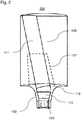
- Fig. 2 shows a cross-sectional view of the milling blank 100, in which a possible shape of the abutment attachment 107 is shown.
- the fastening screw is inserted from above into the feed channel 111 and then slides into the screw channel 105 for fastening the finished abutment attachment 107.
- the screw channel 105 has a conical section 113 for inserting a fastening screw with a conical neck, which widens upwards. This has the advantage that a fastening screw with a conical neck can be used, which transmits the pressing force over a large area to the milled abutment attachment 107 and, because of its conical shape, improves the strength and stability of the entire structure.
- the angle of the feed channel 111 with respect to the screw channel 105 corresponds to half the opening angle of the conical section 113.
- a straight transition can be achieved in a partial area between the feed channel 111 and the conical section 113, so that an inserted fastening screw slides into the screw channel 105 without hindrance can. Otherwise, the transition between the feed channel 111 and the conical section 113 is rounded, so that the feed channel 111 merges into the screw channel 105 without edges.
- the feed channel 111 and the screw channel 105 are designed in such a way that an inverted Allen fastening screw (inverse Allen), such as a screw with a hexagon projection, can be used, by means of which significantly lower force peaks are generated during the fastening.
- inverse Allen inverted Allen fastening screw
- the conical section 113 has a height of 1 mm to 5 mm, for example, and is completely formed within the fastening section 103.
- the milling blank 100 can be provided in the region of the conical section with a coating made of titanium nitride, a diamond or a carbon material, so that the fastening screw can be screwed in with little resistance.
- the fastening section 103 merges continuously and without corners into the milling section 109, which is formed by a cylindrical milling body.
- the fastening section 103 comprises a transition section 119 which continuously merges into the milling section 109.
- the contour of the transition section 119 has a concave, inwardly curved shape.
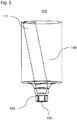
- Fig. 3 shows a further view of the milling blank 100.
- the opening 115 of the feed channel 111 lies in the edge region of the circular surface which is formed by the upper side of the cylindrical milling section 109.
- the feed channel 111 in the area of the connection to the screw channel 105 can also have a widening compared to a cylindrical shape. The widening is produced, for example, by additionally feeding the feed channel 111 in the transition region to the screw channel 105 during the production of the milling blank 100. This has the advantage that larger angles can be realized between the feed channel 111 and the screw channel 105, since the fastening screw can be guided around the angle point in the interior of the milled abutment attachment.
- Fig. 4 shows a further cross-sectional view of the milling blank 100.
- the fastening section 103 widens increasingly towards the milling section 109, so that a smooth and edge-free transition between the fastening section 103 and the milling section 109 is achieved on the outside of the milling blank 100.
- This has the advantage that the largest possible part of the abutment attachment is prefabricated and does not have to be machined by a milling center.
- the angle between the screw channel 105 and the feed channel 111 is advantageously in the range from 5 ° to 20 °. In this area, both the insertion of the fastening screw and the production of an abutment attachment with lateral offset are possible in a technically particularly simple manner.
- Fig. 5 shows a further view of the milling blank 100.
- the fastening section 103 is arranged on the axis of symmetry of the cylindrical milling section 109.
- a CAD library for abutment design software which takes into account the special position and angle of the feed channel 111 within the milling blank 100.
- a base file forms a data record that defines a spatial area in which the milling section must not be milled away. This can prevent the channel wall thickness of the milled abutment attachment from becoming too thin.
- a computer program product which comprises a program that can be loaded directly into a memory of a programmable milling device, with program means for milling a milling blank when the program is executed by the milling device.
Landscapes
- Health & Medical Sciences (AREA)
- Oral & Maxillofacial Surgery (AREA)
- Dentistry (AREA)
- Epidemiology (AREA)
- Life Sciences & Earth Sciences (AREA)
- Animal Behavior & Ethology (AREA)
- General Health & Medical Sciences (AREA)
- Public Health (AREA)
- Veterinary Medicine (AREA)
- Orthopedic Medicine & Surgery (AREA)
- Dental Prosthetics (AREA)
- Milling Processes (AREA)
Description
- Die vorliegende Erfindung betrifft einen Fräsrohling zur Herstellung eines Abutmentaufsatzes.
- Die Druckschrift
EP 2 343 025 A2 beschreibt einen Fräsrohling für einen Abutmentaufsatz mit einem zentralen, geraden Schraubkanal zum Einführen einer Befestigungsschraube und zum Befestigen des gefrästen Abutmentaufsatzes. - Aus der Druckschrift
WO 2013/004 387 A1 ist ein Fräsrohling mit einem schrägen Schraubenkanal bekannt, der auf einem Implantat mithilfe einer Schraube aufgeschraubt wird. Der Fräsrohling hat gegenüber dem Implantat entweder eine plane Unterseite mit einem kleinen Einführkonus oder mit einem zylindrischen, dünnwandigen Einführzapfen. - Die Druckschrift
EP 1 728 486 A1 beschreibt eine zwischen einem Implantatkörper und einem Fräsrohling gelegene Schnittstelle. Der im wesentlichen rotationssymmetrische Fräsrohling hat eine zentrale, gerade zweistufige Bohrung. Im Schnittstellenbereich hat er einen konischen Abschnitt, einen Verdrehsicherungsabschnitt und einen zylindrischen Abschnitt. - Wird allerdings ein Abutmentaufsatz mit einer seitlich versetzten oder asymmetrischen Klebebasis aus dem Fräsrohling hergestellt, wird der zentrale Schraubkanal seitlich teilweise frei gelegt. Dadurch verringern sich die Klebefläche der Klebebasis und die Stabilität des Abutmentaufsatzes.
- Es ist die der Erfindung zugrundeliegende Aufgabe, einen Fräsrohling anzugeben, mit dem ein Abutmentaufsatz mit seitlich versetzter Klebebasis hergestellt werden kann, der eine hohe Stabilität und große Klebefläche aufweist.
- Diese Aufgabe wird durch Gegenstände mit den Merkmalen nach dem unabhängigen Anspruch gelöst. Vorteilhafte Ausführungsformen der Erfindung sind Gegenstand der Figuren, der Beschreibung und der abhängigen Ansprüche.
- Gemäß einem ersten Aspekt der Erfindung wird die Aufgabe durch einen Fräsrohling gelöst, der auf einem Kieferimplantat befestigbar ist
- wobei der Fräsrohling einen Befestigungsabschnitt mit einem Schraubkanal für eine Befestigungsschraube zur Befestigung des gefrästen Abutmentaufsatzes auf einem Kieferimplantat aufweist,
- wobei der Schraubkanal einen konischen Abschnitt zum Einsetzen einer Befestigungsschraube mit konischem Hals umfasst,
- wobei der konische Abschnitt im Befestigungsabschnitt angeordnet ist,
- wobei der Fräsrohling einen Fräsabschnitt mit einem gegenüber dem Schraubkanal abgewinkelten Zuführkanal zum Zuführen der Befestigungsschraube zu dem Schraubkanal aufweist,
- wobei der Zuführkanal kantenlos in den Schraubkanal übergeht,
- wobei der Zuführkanal auf der Oberseite des zylindrischen Fräsabschnitts eine Öffnung hat, die im Randbereich der kreisförmigen Fläche liegt, die durch die Oberseite des zylindrischen Fräsabschnitts gebildet wird und
- wobei der Befestigungsabschnitt sich zum Fräsabschnitt hin verbreitert und der Befestigungsabschnitt mittels eines Übergangsabschnitts kontinuierlich und ohne Ecken in den Fräsabschnitt übergeht und dabei der Übergangsabschnitt eine konkave, nach innen gewölbte Form aufweist.
- Der Schraubkanal und der Zuführkanal weisen beispielsweise eine zylindrische Grundform auf. Der Fräsabschnitt weist reinen größeren Durchmesser als der Befestigungsabschnitt auf und dient zum Herausfräsen des Abutmentaufsatzes.
- Dadurch wird beispielsweise der technische Vorteil erreicht, dass nach der Herstellung eines Abutmentaufsatzes mit einer seitlich versetzten oder asymmetrischen Klebebasis der Zuführkanal im Inneren des Abutmentaufsatzes verläuft und die Klebefläche erhöht sich. Der Fräsrohling mit abgewinkeltem Zuführkanal dient zur Weiterbearbeitung auf Fräszentren in Labors oder Praxen, so dass ein individueller Abutmentaufsatz erstellt werden kann.
- In der erfindungsgemäßen Ausführungsform des Fräsrohlings umfasst der Schraubkanal einen konischen Abschnitt zum Einsetzen einer Befestigungsschraube mit konischem Hals. Dadurch wird beispielsweise der technische Vorteil erreicht, dass eine kantenlose Befestigungsschraube mit konischem Hals verwendet werden kann. Mit einer derartigen Befestigungsschraube wird eine formschlüssige Verbindung hergestellt und die ausgeübte Kraft verteilt sich großflächig. Hohlräume, in denen sich Bakterien einnisten können, werden minimiert. Durch die konische Ausgestaltung wird der gesamte Übergang von Implantat in den Abutmentaufsatz deutlich gegenüber einer konventionellen Schraube mit Kopf und geradem Schaft verstärkt. Die Stabilität des Abutmentaufsatzes erhöht sich hierdurch um ein Viertel.
- In einer weiteren vorteilhaften Ausführungsform des Fräsrohlings entspricht der Winkel des Zuführkanals gegenüber dem Schraubkanal dem halben Öffnungswinkel des konischen Abschnittes. Dadurch wird beispielsweise der technische Vorteil erreicht, dass ein glatter und nahtloser Übergang zwischen Zuführkanal und Schraubkanal realisiert werden kann.
- In einer weiteren vorteilhaften Ausführungsform des Fräsrohlings weist der konische Abschnitt eine Höhe von 1 mm bis 5 mm auf. Dadurch wird beispielsweise der technische Vorteil erreicht, dass die Stabilität des gefrästen und eingesetzten Abutmentaufsatzes verbessert wird.
- In der erfindungsgemäßen Ausführungsform des Fräsrohlings ist der konische Abschnitt im Befestigungsabschnitt angeordnet. Dadurch wird beispielsweise der technische Vorteil erreicht, dass innerhalb des Fräsabschnitts ein gerader Zuführkanal gebildet wird und sich die Stabilität des Fräsrohlings und des daraus gefrästen Abutmentaufsatzes verbessert.
- In einer weiteren vorteilhaften Ausführungsform des Fräsrohlings weist der konische Abschnitt eine Titannitrid-Beschichtung, eine Diamant-Beschichtung oder eine Carbon-Beschichtung auf. Dadurch wird beispielsweise der technische Vorteil erreicht, dass die Befestigungsschraube leichtgängig gegenüber dem konischen Abschnitt eindrehbar ist.
- In der erfindungsgemäßen Ausführungsform des Fräsrohlings ist der Fräsabschnitt zylinderförmig. Dadurch wird beispielsweise der technische Vorteil erreicht, dass der Fräsabschnitt beim Fräsen gleichmäßig bearbeitet werden kann.
- In einer weiteren vorteilhaften Ausführungsform des Fräsrohlings ist der Befestigungsabschnitt auf der Achse des zylinderförmigen Fräsabschnittes angeordnet. Dadurch wird beispielsweise der technische Vorteil erreicht, dass der Fräsrohling mit dem Befestigungsabschnitt in ein Fräswerkzeug eingesetzt werden kann.
- In der erfindungsgemäßen Ausführungsform des Fräsrohlings geht der Zuführkanal kantenlos in den Schraubkanal über. Dadurch wird beispielsweise der technische Vorteil erreicht, dass ein Verkanten der Befestigungsschraube beim Einsetzen verhindert wird.
- In der erfindungsgemäßen Ausführungsform des Fräsrohlings liegt eine Öffnung des Zuführkanals im Randbereich einer dem Befestigungsabschnitt gegenüberliegenden Fläche des Fräsabschnitts. Dadurch wird beispielsweise der technische Vorteil erreicht, dass eine große Neigung des Zuführkanals erreicht wird.
- In der erfindungsgemäßen Ausführungsform des Fräsrohlings verbreitert sich der Befestigungsabschnitt zum Fräsabschnitt hin. Dadurch wird beispielsweise der technische Vorteil erreicht, dass der Befestigungsabschnitt eine stabile Basis für den Fräsabschnitt bildet.
- In einer weiteren vorteilhaften Ausführungsform des Fräsrohlings umfasst der Befestigungsabschnitt einen Sechskantabschnitt zum Einsetzen in eine Sechskantaussparung. Dadurch wird beispielsweise der technische Vorteil erreicht, dass der Befestigungsabschnitt eine Schnittstelle zu allen führenden Implantaten aufweist.
- In einer weiteren vorteilhaften Ausführungsform des Fräsrohlings ist der Winkel zwischen dem Schraubkanal und dem Zuführkanal im Bereich von 5° bis 20°. Vorzugsweise beträgt der Winkel zwischen dem Schraubkanal und dem Zuführkanal 11°. Dadurch wird beispielsweise der technische Vorteil erreicht, dass der Zuführkanal in einem besonders geeigneten Winkelbereich liegt, in dem sowohl ein Einsetzen der Befestigungsschraube als auch die Herstellung eines Abutmentaufsatzes mit seitlichem Versatz ermöglicht wird.
- In einer weiteren vorteilhaften Ausführungsform des Fräsrohlings ist der Zuführkanal im Bereich der Verbindung zu dem Schraubkanal verbreitert. Dadurch wird beispielsweise ebenfalls der technische Vorteil erreicht, dass ein Einsetzen der Befestigungsschraube in den Schraubkanal über den Zuführkanal erleichtert wird.
- In einer weiteren vorteilhaften Ausführungsform des Fräsrohlings umfasst der Fräsrohling an einer dem Befestigungsabschnitt gegenüberliegenden Fläche des Fräsabschnitts eine mittige Aussparung zum Einsetzen eines Drehwerkzeuges. Dadurch wird beispielsweise der technische Vorteil erreicht, dass der Fräsrohling auf einfache Weise in ein Drehwerkzeug eingesetzt werden kann.
- Nachfolgend ist in einem zweiten Aspekt ein Verfahren zum Herstellen eines Abutmentaufsatzes mit dem Schritt eines Fräsens eines erfindungsgemäßen Fräsrohlings offenbart. Dadurch wird beispielsweise der technische Vorteil erreicht, dass sich der Abutmentaufsatz auf einfache Weise herstellen lässt.
- In einer vorteilhaften Ausführungsform des Verfahrens umfasst das Verfahren den Schritt eines Verarbeitens eines Datensatzes, der einen räumlichen Bereich innerhalb des Fräsrohlings um den Zuführkanal herum definiert, in dem keine Bearbeitung des Fräsrohlings durch das Verfahren erfolgt. Dadurch wird beispielsweise der technische Vorteil erreicht, dass eine Kanalwandstärke des gefrästen Abutmentaufsatzes um den abgewinkelten Zuführkanal herum eine vorgegebene Mindeststärke aufweist.
- Nachfolgend ist in einem dritten Aspekt ein Computerprogrammprodukt offenbart, das ein Programm umfasst, das direkt in einen Speicher einer programmierbaren Fräseinrichtung ladbar ist, mit Programmmitteln zum Fräsen eines Fräsrohlings nach dem ersten Aspekt, wobei das Computerprogrammprodukt weiter einen Datensatz umfasst, der einen räumlichen Bereich innerhalb des Fräsrohlings um den abgewinkelten Zuführkanal herum definiert, in dem keine Bearbeitung des Fräsrohlings durch die Fräseinrichtung erfolgt oder eine Bearbeitung des Fräsrohlings durch die Fräseinrichtung unterbleibt. Dadurch wird beispielsweise ebenfalls der technische Vorteil erreicht, dass eine Kanalwandstärke des gefrästen Abutmentaufsatzes um den abgewinkelten Zuführkanal herum eine vorgegebene Mindeststärke aufweist.
- Ausführungsbeispiele der Erfindung sind in den Zeichnungen dargestellt und werden im Folgenden näher beschrieben.
- Es zeigen:
- Fig. 1
- eine Ansicht eines Fräsrohlings mit abgewinkeltem Zuführkanal;
- Fig. 2
- eine Querschnittsansicht des Fräsrohlings;
- Fig. 3
- eine weitere Ansicht des Fräsrohlings;
- Fig. 4
- eine weitere Querschnittsansicht des Fräsrohlings; und
- Fig. 5
- eine weitere Ansicht des Fräsrohlings.
-
Fig. 1 zeigt eine Ansicht eines Fräsrohlings 100 mit einem gegenüber einem zylindrischen Schraubkanal 105 abgewinkelten, zylindrischen Zuführkanal 111 für eine Befestigungsschraube. Der Fräsrohling 100 dient zum Herstellen eines Abutmentaufsatzes, der als Aufbauteil auf einem Kieferimplantat für eine Zahnprothese befestigt wird. Der gefräste Abutmentaufsatz umfasst eine Klebebasis, die beispielsweise zum Aufkleben eines Klebekörpers dient. Durch individuelles Fräsen des Fräsrohlings ist es möglich, einen auf den Patienten angepassten Abutmentaufsatz herzustellen. - Der Fräsrohling 100 kann beispielsweise aus Titan vom Grad 5 (Ti-6Al-4V) hergestellt sein, so dass eine hohe Festigkeit mit guter Zähigkeit bei gleichzeitig geringer Dichte gegeben ist. Insbesondere sind bei diesem Material gute Fräseigenschaften gegeben. Im Allgemeinen können jedoch auch andere geeignete Materialien verwendet werden.
- Der Fräsrohling 100 umfasst einen vorgefertigten Befestigungsabschnitt 103, der zum Befestigen des gefrästen Abutmentaufsatzes auf dem Kieferimplantat verwendet wird und der zu diesem Zweck nicht weiter bearbeitet wird. Dieser Befestigungsabschnitt 103 bildet beispielsweise eine vorgefertigte Schnittstelle zu allen führenden Implantaten. Zu diesem Zweck weist der Befestigungsabschnitt 103 beispielsweise einen Sechskantabschnitt 117 zum Einsetzen in eine Sechskantaussparung des Kieferimplantats auf.
- Im Befestigungsabschnitt 103 befindet sich ein Schraubkanal 105, in den eine Befestigungsschraube zum Befestigen des Abutmentaufsatzes auf dem Kieferimplantat eingeführt wird. Die Befestigungsschraube übt nach dem Anziehen über den Schraubkanal 105 eine Kraft auf den Abutmentaufsatz aus, so dass dieser fest und unverdrehbar auf dem Kieferimplantat sitzt. Der Schraubkanal 105 weist einen konischen Abschnitt 113 auf.
- Innerhalb des Fräsabschnitts 109 verläuft ein gegenüber dem Schraubkanal 105 mit dem Winkel α abgewinkelter Zuführkanal 111 zum Zuführen der Befestigungsschraube zu dem Schraubkanal 105. Die Öffnung 115 des Zuführkanals 111 befindet sich an der Oberseite des zylindrischen Fräsabschnittes 109.
-
Fig. 2 zeigt eine Querschnittsansicht des Fräsrohlings 100, in der eine mögliche Form des Abutmentaufsatzes 107 eingezeichnet ist. Die Befestigungsschraube wird von oben in den Zuführkanal 111 eingeführt und gleitet dann in den Schraubkanal 105 zur Befestigung des fertigen Abutmentaufsatzes 107. Der Schraubkanal 105 weist einen konischen Abschnitt 113 zum Einsetzen einer Befestigungsschraube mit konischem Hals auf, der sich nach oben hin aufweitet. Dadurch wird der Vorteil erreicht, dass eine Befestigungsschraube mit konischen Hals verwendet werden kann, die die Andrückkraft großflächig auf den gefrästen Abutmentaufsatz 107 überträgt und aufgrund ihrer konischen Form die Festigkeit und Stabilität des gesamten Aufbaus verbessert. - Der Winkel des Zuführkanals 111 gegenüber dem Schraubkanal 105 entspricht dem halben Öffnungswinkel des konischen Abschnittes 113. Dadurch kann in einem Teilbereich zwischen dem Zuführkanal 111 und dem konischen Abschnitt 113 ein gerader Übergang erreicht werden, so dass eine eingesetzte Befestigungsschraube ohne Behinderung in den Schraubkanal 105 gleiten kann. Ansonsten ist der Übergang zwischen dem Zuführkanal 111 und dem konischen Abschnitt 113 abgerundet, so dass der Zuführkanal 111 kantenlos in den Schraubkanal 105 übergeht.
- Der Zuführkanal 111 und der Schraubkanal 105 sind derart gestaltet, dass eine umgekehrte Imbus-Befestigungsschraube (Inverse-Imbus), wie beispielsweise eine Schraube mit einem Sechskantvorsprung, verwendet werden kann, durch die deutlich geringere Kraftspitzen bei der Befestigung erzeugt werden.
- Der konische Abschnitt 113 weist beispielsweise eine Höhe von 1 mm bis 5 mm auf und ist vollständig innerhalb des Befestigungsabschnittes 103 gebildet. Außerdem kann der Fräsrohling 100 im Bereich des konischen Abschnittes mit einer Beschichtung aus Titannitrid-, eine Diamant- oder eine Carbonmaterial versehen sein, so dass die Befestigungsschraube mit geringem Widerstand eingedreht werden kann.
- Der Befestigungsabschnitt 103 geht kontinuierlich und ohne Ecken in den Fräsabschnitt 109 über, der durch einen zylindrischen Fräskörper gebildet wird. Zu diesem Zweck umfasst der Befestigungsabschnitt 103 einen Übergangsabschnitt 119, der der kontinuierlich in den Fräsabschnitt 109 übergeht. Die Kontur des Übergangsabschnittes 119 weist eine konkave, nach innen gewölbte Form auf. Dadurch kann auf der Außenseite des Fräsrohlings 100 ein ecken- und kantenloser Übergang zwischen dem Befestigungsabschnitt 103 und dem Fräsabschnitt 109 erreicht werden und die Stabilität des Abutmentaufsatzes verbessert sich. Aus dem Fräsrohling 100 wird bei der Weiterbearbeitung auf Fräszentren in Labors oder Praxen der individuelle Teil des Abutmentaufsatzes hergestellt.
-
Fig. 3 zeigt eine weitere Ansicht des Fräsrohlings 100. Die Öffnung 115 des Zuführkanals 111 liegt im Randbereich der kreisförmigen Fläche, die durch die Oberseite des zylindrischen Fräsabschnitts 109 gebildet wird. Im Allgemeinen kann der Zuführkanal 111 im Bereich der Verbindung zu dem Schraubkanal 105 ebenfalls eine Verbreiterung gegenüber einer zylindrischen Form aufweisen. Die Verbreiterung wird beispielsweise dadurch erzeugt, dass bei der Herstellung des Fräsrohlings 100 der Zuführkanal 111 im Übergangsbereich zu dem Schraubkanal 105 zusätzlich ausgefräst wird. Dadurch wird der Vorteil erreicht, dass sich größere Winkel zwischen Zuführkanal 111 und Schraubkanal 105 realisieren lassen, da die Befestigungsschraube im Inneren des gefrästen Abutmentaufsatzes um die Winkelstelle herumgeführt werden kann. -
Fig. 4 zeigt eine weitere Querschnittsansicht des Fräsrohlings 100. Der Befestigungsabschnitt 103 verbreitert sich zum Fräsabschnitt 109 hin zunehmend, so dass auf der Außenseite des Fräsrohlings 100 ein glatter und kantenfreier Übergang zwischen dem Befestigungsabschnitt 103 und dem Fräsabschnitt 109 erreicht wird. Dadurch wird der Vorteil erreicht, dass ein möglichst großer Teil des Abutmentaufsatzes vorgefertigt ist und von einem Fräszentrum nicht bearbeitet werden muss. - Der Winkel zwischen dem Schraubkanal 105 und dem Zuführkanal 111 liegt vorteilhafterweise im Bereich von 5° bis 20°. In diesem Bereich ist sowohl ein Einsetzen der Befestigungsschraube als auch die Herstellung eines Abutmentaufsatzes mit seitlichem Versatz auf technisch besonders einfache Art und Weise möglich.
-
Fig. 5 zeigt eine weitere Ansicht des Fräsrohlings 100. Der Befestigungsabschnitt 103 ist auf der Symmetrieachse des zylinderförmigen Fräsabschnittes 109 angeordnet. Für den Fräsrohling 100 mit abgewinkeltem Zuführkanal 111 kann zur weiteren Verarbeitung durch ein Fräszentrum eine CAD-Bibliothek für Abutment-Konstruktionssoftware vorgesehen sein, die die spezielle Lage und Abwinklung des Zuführkanals 111 innerhalb des Fräsrohlings 100 berücksichtigt. Ein Basefile bildet einen Datensatz, der einen räumlichen Bereich definiert, in dem kein Wegfräsen des Fräsabschnittes erfolgen darf. Dadurch kann verhindert werden, dass die Kanalwandstärke des gefrästen Abutmentaufsatzes zu dünn wird. - Zu diesem Zweck kann ein Computerprogrammprodukt vorgesehen sein, das ein Programm umfasst, das direkt in einen Speicher einer programmierbaren Fräseinrichtung ladbar ist, mit Programmmitteln zum Fräsen eines Fräsrohlings, wenn das Programm durch die Fräseinrichtung ausgeführt wird.
- Alle in Verbindung mit einzelnen Ausführungsformen der Erfindung erläuterten und gezeigten Merkmale können in unterschiedlicher Kombination in dem erfindungsgemäßen Gegenstand vorgesehen sein, um gleichzeitig deren vorteilhafte Wirkungen zu realisieren.
- Der Schutzbereich der vorliegenden Erfindung ist durch die Ansprüche gegeben und wird durch die in der Beschreibung erläuterten oder den Figuren gezeigten Merkmale nicht beschränkt.
-
- 100
- Fräsrohling
- 103
- Befestigungsabschnitt
- 105
- Schraubkanal
- 107
- Abutmentaufsatz
- 109
- Fräsabschnitt
- 111
- Zuführkanal
- 113
- konischer Abschnitt
- 115
- Öffnung
- 117
- Sechskantabschnitt
- 119
- Übergangsabschnitt
Claims (8)
- Fräsrohling (100) zur Herstellung eines Abutmentaufsatzes (107), der auf einem Kieferimplantat befestigbar ist- wobei der Fräsrohling (100) einen Befestigungsabschnitt (103) mit einem Schraubkanal (105) für eine Befestigungsschraube zur Befestigung des gefrästen Abutmentaufsatzes (107) auf einem Kieferimplantat aufweist,- wobei der Schraubkanal (105) einen konischen Abschnitt (113) zum Einsetzen einer Befestigungsschraube mit konischem Hals umfasst,- wobei der konische Abschnitt (113) im Befestigungsabschnitt (103) angeordnet ist,- wobei der Fräsrohling (100) einen Fräsabschnitt (109) mit einem gegenüber dem Schraubkanal (105) abgewinkelten Zuführkanal (111) zum Zuführen der Befestigungsschraube zu dem Schraubkanal (105) aufweist,- wobei der Zuführkanal (111) kantenlos in den Schraubkanal (105) übergeht,- wobei der Zuführkanal (111) auf der Oberseite des zylindrischen Fräsabschnitts (109) eine Öffnung (115) hat, die im Randbereich der kreisförmigen Fläche liegt, die durch die Oberseite des zylindrischen Fräsabschnitts (109) gebildet wird und- wobei der Befestigungsabschnitt (103) sich zum Fräsabschnitt (109) hin verbreitert und der Befestigungsabschnitt (103) mittels eines Übergangsabschnitts (119) kontinuierlich und ohne Ecken in den Fräsabschnitt (109) übergeht und dabei der Übergangsabschnitt (119) eine konkave, nach innen gewölbte Form aufweist.
- Fräsrohling (100) nach Anspruch 1, wobei der Winkel (α) des Zuführkanals (111) gegenüber dem Schraubkanal (105) dem halben Öffnungswinkel des konischen Abschnittes (113) entspricht.
- Fräsrohling (100) nach einem der Ansprüche 1 oder 2, wobei der konische Abschnitt (113) eine Höhe von 1 mm bis 5 mm aufweist.
- Fräsrohling (100) nach einem der Ansprüche 1 bis 3, wobei der konische Abschnitt (113) eine Titannitrid-Beschichtung, eine Diamant-Beschichtung oder eine Carbon-Beschichtung aufweist.
- Fräsrohling (100) nach Anspruch 1, wobei der Befestigungsabschnitt (103) auf der Achse des zylinderförmigen Fräsabschnittes (109) angeordnet ist.
- Fräsrohling (100) nach einem der vorangehenden Ansprüche, wobei sich der Befestigungsabschnitt (103) zum Fräsabschnitt (109) hin verbreitert.
- Fräsrohling (100) nach einem der vorangehenden Ansprüche, wobei des Befestigungsabschnitts (103) einen Sechskantabschnitt (117) zum Einsetzen in eine Sechskantaussparung umfasst.
- Fräsrohling (100) nach einem der vorangehenden Ansprüche, wobei der Winkel zwischen dem Schraubkanal (105) und dem Zuführkanal (111) im Bereich von 5°bis 20° liegt.
Applications Claiming Priority (2)
| Application Number | Priority Date | Filing Date | Title |
|---|---|---|---|
| DE102013102402.5A DE102013102402B4 (de) | 2013-03-11 | 2013-03-11 | Fräsrohling für einen abutmentaufsatz |
| PCT/EP2014/054686 WO2014140002A1 (de) | 2013-03-11 | 2014-03-11 | Fräsrohling für einen abutmentaufsatz |
Publications (2)
| Publication Number | Publication Date |
|---|---|
| EP2967769A1 EP2967769A1 (de) | 2016-01-20 |
| EP2967769B1 true EP2967769B1 (de) | 2020-04-29 |
Family
ID=50115836
Family Applications (1)
| Application Number | Title | Priority Date | Filing Date |
|---|---|---|---|
| EP14708905.6A Not-in-force EP2967769B1 (de) | 2013-03-11 | 2014-03-11 | Fräsrohling für einen abutmentaufsatz |
Country Status (8)
| Country | Link |
|---|---|
| US (1) | US20160022390A1 (de) |
| EP (1) | EP2967769B1 (de) |
| KR (1) | KR101982823B1 (de) |
| CN (1) | CN105283148B (de) |
| BR (1) | BR112015022822B1 (de) |
| DE (1) | DE102013102402B4 (de) |
| ES (1) | ES2805373T3 (de) |
| WO (1) | WO2014140002A1 (de) |
Families Citing this family (10)
| Publication number | Priority date | Publication date | Assignee | Title |
|---|---|---|---|---|
| WO2016170198A1 (es) * | 2015-04-23 | 2016-10-27 | Esteban Xam-Mar Mangrane | Bloque para la fabricacion de muñones individualizados para implantologia dental y procedimiento de fabricación de un muñon personalizado para implantologia dental |
| ES2807949T3 (es) * | 2016-01-21 | 2021-02-24 | Xam Mar Mangrane Esteban | Método para la producción de una estructura dental |
| EP3231391B1 (de) | 2016-04-14 | 2018-12-26 | Neoss Limited | Schraubendreher und schraube für medizinische anwendungen, insbesondere für zahnärztliche anwendungen |
| DE102016008668B4 (de) * | 2016-07-20 | 2018-10-25 | Bruno Spindler | Suprastrukturträger mit besonderer Innen- und Außengeometrie |
| DE102016116546B4 (de) | 2016-09-05 | 2025-03-27 | Kulzer Gmbh | Mehrfarbiger Fräsrohling für Implantat-getragene dentale, prothetische Versorgungen |
| US10575931B2 (en) * | 2016-11-18 | 2020-03-03 | Michel Matouk | Customized single piece dental implant |
| EP3528740B1 (de) | 2016-12-16 | 2022-12-07 | Neoss Limited | Dentaler abutmentrohling und verfahren zur herstellung einer zahnprothese aus solch einem rohling |
| EP3606463B1 (de) * | 2017-04-07 | 2023-10-25 | Panthera Dental Inc. | Tropfenförmiger schraubkanal für zahnaufbau und entwurfsverfahren dafür |
| US12268564B2 (en) * | 2017-09-12 | 2025-04-08 | Dentsply Sirona Inc. | Blanks and methods for the manufacture of at least one molded blank |
| EP3653167B1 (de) * | 2018-11-15 | 2023-01-25 | Sirona Dental Systems GmbH | Verfahren zur herstellung von dentalen passkörpern und werkstück für diesen zweck |
Citations (3)
| Publication number | Priority date | Publication date | Assignee | Title |
|---|---|---|---|---|
| EP1728486A1 (de) * | 2005-06-03 | 2006-12-06 | Straumann Holding AG | Kupplung für ein mehrteiliges Zahnimplantatsystem |
| EP2343025A2 (de) * | 2010-01-12 | 2011-07-13 | RaphaBio Co., Ltd. | Rohling eines Zahnimplantataufbaus für maßgeschneiderte Herstellung eines Zahnimplantataufbaus und Verfahren zur Herstellung eines Zahnimplantataufbaus |
| US20120237902A1 (en) * | 2011-03-17 | 2012-09-20 | Joseph Maniscalco Dds Pc | Techniques for providing custom-formed implants |
Family Cites Families (14)
| Publication number | Priority date | Publication date | Assignee | Title |
|---|---|---|---|---|
| US758750A (en) * | 1902-09-19 | 1904-05-03 | Haldeman Porcelain Crown Company | Artificial denture. |
| US5180303A (en) * | 1988-09-21 | 1993-01-19 | Regents Of The University Of California | Retrievable dental prothesis apparatus and method of fabrication |
| KR100332383B1 (ko) * | 2000-03-17 | 2002-04-12 | 김영수 | 만곡 인공치아 지대주 |
| EP1430852A3 (de) * | 2002-12-19 | 2004-11-10 | Biogénie Projectos Ltda. | Verfahren zur Herstellung kundengebundener Medico-Dentaler Teile unter Nutzung von Computertechnik, sowie Rohling für die Herstellung prostetischer Komponenten |
| US6991853B2 (en) * | 2003-05-29 | 2006-01-31 | Biogénie Projetos Ltda. | Blank from which a customized prosthetic part can be machined |
| ATE466540T2 (de) * | 2006-08-25 | 2010-05-15 | Biomain Ab | Dentale superstruktur und verfahren zu ihrer herstellung |
| ES2736404T3 (es) * | 2007-09-18 | 2019-12-30 | Biomet 3I Llc | Tornillo para un sistema de implante dental que tiene estabilidad mejorada |
| JP5195285B2 (ja) * | 2007-11-01 | 2013-05-08 | 日立金属株式会社 | インプラント用キーパー及びその組立体 |
| KR100912271B1 (ko) * | 2008-10-20 | 2009-08-17 | 주식회사 쎄타텍 | 크라운 일체형 지대주 및 그 제작방법 |
| GB2494099A (en) * | 2011-07-06 | 2013-03-06 | Nobel Biocare Services Ag | Dental component with an angled screw channel |
| WO2013050796A1 (en) * | 2011-10-04 | 2013-04-11 | Elsner Edvin | Channel formation for the fixing element of a dental superstructure and method of making the same |
| KR20130097820A (ko) * | 2012-02-25 | 2013-09-04 | 이종호 | 자유각도 임플란트 개인 맞춤 지대주 제작을 위해 미리 가공된 자유각도 임플란트 개인 맞춤 지대주 블랭크 |
| EP2653131B1 (de) * | 2012-04-19 | 2018-02-28 | Dentsply IH AB | Zahnimplantatset |
| DE202012102746U1 (de) * | 2012-07-18 | 2012-08-22 | Curd Gadau | Zahnimplantataufbausystem |
-
2013
- 2013-03-11 DE DE102013102402.5A patent/DE102013102402B4/de not_active Expired - Fee Related
-
2014
- 2014-03-11 WO PCT/EP2014/054686 patent/WO2014140002A1/de not_active Ceased
- 2014-03-11 BR BR112015022822-4A patent/BR112015022822B1/pt not_active IP Right Cessation
- 2014-03-11 CN CN201480024172.0A patent/CN105283148B/zh active Active
- 2014-03-11 ES ES14708905T patent/ES2805373T3/es active Active
- 2014-03-11 EP EP14708905.6A patent/EP2967769B1/de not_active Not-in-force
- 2014-03-11 US US14/775,116 patent/US20160022390A1/en not_active Abandoned
- 2014-03-11 KR KR1020157028228A patent/KR101982823B1/ko active Active
Patent Citations (3)
| Publication number | Priority date | Publication date | Assignee | Title |
|---|---|---|---|---|
| EP1728486A1 (de) * | 2005-06-03 | 2006-12-06 | Straumann Holding AG | Kupplung für ein mehrteiliges Zahnimplantatsystem |
| EP2343025A2 (de) * | 2010-01-12 | 2011-07-13 | RaphaBio Co., Ltd. | Rohling eines Zahnimplantataufbaus für maßgeschneiderte Herstellung eines Zahnimplantataufbaus und Verfahren zur Herstellung eines Zahnimplantataufbaus |
| US20120237902A1 (en) * | 2011-03-17 | 2012-09-20 | Joseph Maniscalco Dds Pc | Techniques for providing custom-formed implants |
Also Published As
| Publication number | Publication date |
|---|---|
| WO2014140002A1 (de) | 2014-09-18 |
| KR101982823B1 (ko) | 2019-05-29 |
| DE102013102402A1 (de) | 2014-09-11 |
| US20160022390A1 (en) | 2016-01-28 |
| DE102013102402B4 (de) | 2018-10-11 |
| BR112015022822A2 (pt) | 2017-07-18 |
| BR112015022822B1 (pt) | 2021-02-23 |
| KR20160007494A (ko) | 2016-01-20 |
| EP2967769A1 (de) | 2016-01-20 |
| ES2805373T3 (es) | 2021-02-11 |
| CN105283148B (zh) | 2017-11-21 |
| CN105283148A (zh) | 2016-01-27 |
Similar Documents
| Publication | Publication Date | Title |
|---|---|---|
| DE102013102402B4 (de) | Fräsrohling für einen abutmentaufsatz | |
| EP2525737B1 (de) | Abutment für ein Zahnimplantat und Kombination aus Abutment und Implantat | |
| DE69325511T2 (de) | Verfahren zur herstellung einer zahnprothese zum einbau in einem implantat | |
| EP3790497B1 (de) | Implantataufbau für ein enossales zahnimplantat | |
| EP3636210B1 (de) | Suprakonstruktion | |
| EP3661452B1 (de) | Abutment zum halten eines zahnersatzes an einem kieferimplantat | |
| WO2015181092A1 (de) | Zahnersatz-erzeugungsvorrichtung sowie zahnersatz | |
| EP3410979B1 (de) | Abutment, insbesondere zur verwendung mit einem in den kieferknochen eines patienten inserierten dentalimplantat, und verfahren zur herstellung des abutments | |
| DE102013102411B4 (de) | Abutmentaufsatz für ein kieferimplantat | |
| DE102005027184B4 (de) | Modellimplantat für Zahnimplantate | |
| EP2056735B1 (de) | Magnetisches abdrucksystem | |
| EP3634299B1 (de) | Zahnprothese | |
| EP2825124B1 (de) | Aufsatz für ein korrespondierendes stiftförmiges zahnimplantat | |
| DE60012643T2 (de) | Zahnimplantat | |
| DE202006001796U1 (de) | Zahnimplantat | |
| DE102018120901A1 (de) | Zahnprothese | |
| DE202017105987U1 (de) | Abutment | |
| DE202018104914U1 (de) | Zahnprothese | |
| DE102011009743B4 (de) | Abutment-System für ein Schraubenimplantat in einem Kieferknochen | |
| DE202011002075U1 (de) | Abutment-System für ein Schraubenimplantat in einem Kieferknochen | |
| EP3501437A1 (de) | Knochenplatte und verfahren zum herstellen einer knochenplatte | |
| DE202010015226U1 (de) | Implantat | |
| WO2016142066A1 (de) | Modellierungssystem für implantatgestütztes zahnersatzelement und seine verwendung |
Legal Events
| Date | Code | Title | Description |
|---|---|---|---|
| PUAI | Public reference made under article 153(3) epc to a published international application that has entered the european phase |
Free format text: ORIGINAL CODE: 0009012 |
|
| 17P | Request for examination filed |
Effective date: 20151002 |
|
| AK | Designated contracting states |
Kind code of ref document: A1 Designated state(s): AL AT BE BG CH CY CZ DE DK EE ES FI FR GB GR HR HU IE IS IT LI LT LU LV MC MK MT NL NO PL PT RO RS SE SI SK SM TR |
|
| AX | Request for extension of the european patent |
Extension state: BA ME |
|
| DAX | Request for extension of the european patent (deleted) | ||
| RAP1 | Party data changed (applicant data changed or rights of an application transferred) |
Owner name: SPINDLER, BRUNO |
|
| RIN1 | Information on inventor provided before grant (corrected) |
Inventor name: SPINDLER, BRUNO |
|
| STAA | Information on the status of an ep patent application or granted ep patent |
Free format text: STATUS: EXAMINATION IS IN PROGRESS |
|
| 17Q | First examination report despatched |
Effective date: 20180503 |
|
| GRAP | Despatch of communication of intention to grant a patent |
Free format text: ORIGINAL CODE: EPIDOSNIGR1 |
|
| STAA | Information on the status of an ep patent application or granted ep patent |
Free format text: STATUS: GRANT OF PATENT IS INTENDED |
|
| INTG | Intention to grant announced |
Effective date: 20191126 |
|
| GRAS | Grant fee paid |
Free format text: ORIGINAL CODE: EPIDOSNIGR3 |
|
| GRAA | (expected) grant |
Free format text: ORIGINAL CODE: 0009210 |
|
| STAA | Information on the status of an ep patent application or granted ep patent |
Free format text: STATUS: THE PATENT HAS BEEN GRANTED |
|
| AK | Designated contracting states |
Kind code of ref document: B1 Designated state(s): AL AT BE BG CH CY CZ DE DK EE ES FI FR GB GR HR HU IE IS IT LI LT LU LV MC MK MT NL NO PL PT RO RS SE SI SK SM TR |
|
| REG | Reference to a national code |
Ref country code: GB Ref legal event code: FG4D Free format text: NOT ENGLISH |
|
| REG | Reference to a national code |
Ref country code: CH Ref legal event code: EP |
|
| REG | Reference to a national code |
Ref country code: DE Ref legal event code: R096 Ref document number: 502014014080 Country of ref document: DE |
|
| REG | Reference to a national code |
Ref country code: AT Ref legal event code: REF Ref document number: 1262189 Country of ref document: AT Kind code of ref document: T Effective date: 20200515 |
|
| REG | Reference to a national code |
Ref country code: IE Ref legal event code: FG4D Free format text: LANGUAGE OF EP DOCUMENT: GERMAN |
|
| REG | Reference to a national code |
Ref country code: NL Ref legal event code: MP Effective date: 20200429 |
|
| REG | Reference to a national code |
Ref country code: LT Ref legal event code: MG4D |
|
| PG25 | Lapsed in a contracting state [announced via postgrant information from national office to epo] |
Ref country code: GR Free format text: LAPSE BECAUSE OF FAILURE TO SUBMIT A TRANSLATION OF THE DESCRIPTION OR TO PAY THE FEE WITHIN THE PRESCRIBED TIME-LIMIT Effective date: 20200730 Ref country code: PT Free format text: LAPSE BECAUSE OF FAILURE TO SUBMIT A TRANSLATION OF THE DESCRIPTION OR TO PAY THE FEE WITHIN THE PRESCRIBED TIME-LIMIT Effective date: 20200831 Ref country code: LT Free format text: LAPSE BECAUSE OF FAILURE TO SUBMIT A TRANSLATION OF THE DESCRIPTION OR TO PAY THE FEE WITHIN THE PRESCRIBED TIME-LIMIT Effective date: 20200429 Ref country code: NO Free format text: LAPSE BECAUSE OF FAILURE TO SUBMIT A TRANSLATION OF THE DESCRIPTION OR TO PAY THE FEE WITHIN THE PRESCRIBED TIME-LIMIT Effective date: 20200729 Ref country code: SE Free format text: LAPSE BECAUSE OF FAILURE TO SUBMIT A TRANSLATION OF THE DESCRIPTION OR TO PAY THE FEE WITHIN THE PRESCRIBED TIME-LIMIT Effective date: 20200429 Ref country code: IS Free format text: LAPSE BECAUSE OF FAILURE TO SUBMIT A TRANSLATION OF THE DESCRIPTION OR TO PAY THE FEE WITHIN THE PRESCRIBED TIME-LIMIT Effective date: 20200829 Ref country code: FI Free format text: LAPSE BECAUSE OF FAILURE TO SUBMIT A TRANSLATION OF THE DESCRIPTION OR TO PAY THE FEE WITHIN THE PRESCRIBED TIME-LIMIT Effective date: 20200429 |
|
| PG25 | Lapsed in a contracting state [announced via postgrant information from national office to epo] |
Ref country code: HR Free format text: LAPSE BECAUSE OF FAILURE TO SUBMIT A TRANSLATION OF THE DESCRIPTION OR TO PAY THE FEE WITHIN THE PRESCRIBED TIME-LIMIT Effective date: 20200429 Ref country code: LV Free format text: LAPSE BECAUSE OF FAILURE TO SUBMIT A TRANSLATION OF THE DESCRIPTION OR TO PAY THE FEE WITHIN THE PRESCRIBED TIME-LIMIT Effective date: 20200429 Ref country code: RS Free format text: LAPSE BECAUSE OF FAILURE TO SUBMIT A TRANSLATION OF THE DESCRIPTION OR TO PAY THE FEE WITHIN THE PRESCRIBED TIME-LIMIT Effective date: 20200429 Ref country code: BG Free format text: LAPSE BECAUSE OF FAILURE TO SUBMIT A TRANSLATION OF THE DESCRIPTION OR TO PAY THE FEE WITHIN THE PRESCRIBED TIME-LIMIT Effective date: 20200729 |
|
| PG25 | Lapsed in a contracting state [announced via postgrant information from national office to epo] |
Ref country code: NL Free format text: LAPSE BECAUSE OF FAILURE TO SUBMIT A TRANSLATION OF THE DESCRIPTION OR TO PAY THE FEE WITHIN THE PRESCRIBED TIME-LIMIT Effective date: 20200429 Ref country code: AL Free format text: LAPSE BECAUSE OF FAILURE TO SUBMIT A TRANSLATION OF THE DESCRIPTION OR TO PAY THE FEE WITHIN THE PRESCRIBED TIME-LIMIT Effective date: 20200429 |
|
| PG25 | Lapsed in a contracting state [announced via postgrant information from national office to epo] |
Ref country code: SM Free format text: LAPSE BECAUSE OF FAILURE TO SUBMIT A TRANSLATION OF THE DESCRIPTION OR TO PAY THE FEE WITHIN THE PRESCRIBED TIME-LIMIT Effective date: 20200429 Ref country code: RO Free format text: LAPSE BECAUSE OF FAILURE TO SUBMIT A TRANSLATION OF THE DESCRIPTION OR TO PAY THE FEE WITHIN THE PRESCRIBED TIME-LIMIT Effective date: 20200429 Ref country code: CZ Free format text: LAPSE BECAUSE OF FAILURE TO SUBMIT A TRANSLATION OF THE DESCRIPTION OR TO PAY THE FEE WITHIN THE PRESCRIBED TIME-LIMIT Effective date: 20200429 Ref country code: DK Free format text: LAPSE BECAUSE OF FAILURE TO SUBMIT A TRANSLATION OF THE DESCRIPTION OR TO PAY THE FEE WITHIN THE PRESCRIBED TIME-LIMIT Effective date: 20200429 Ref country code: EE Free format text: LAPSE BECAUSE OF FAILURE TO SUBMIT A TRANSLATION OF THE DESCRIPTION OR TO PAY THE FEE WITHIN THE PRESCRIBED TIME-LIMIT Effective date: 20200429 |
|
| REG | Reference to a national code |
Ref country code: DE Ref legal event code: R097 Ref document number: 502014014080 Country of ref document: DE |
|
| REG | Reference to a national code |
Ref country code: ES Ref legal event code: FG2A Ref document number: 2805373 Country of ref document: ES Kind code of ref document: T3 Effective date: 20210211 |
|
| PG25 | Lapsed in a contracting state [announced via postgrant information from national office to epo] |
Ref country code: PL Free format text: LAPSE BECAUSE OF FAILURE TO SUBMIT A TRANSLATION OF THE DESCRIPTION OR TO PAY THE FEE WITHIN THE PRESCRIBED TIME-LIMIT Effective date: 20200429 Ref country code: SK Free format text: LAPSE BECAUSE OF FAILURE TO SUBMIT A TRANSLATION OF THE DESCRIPTION OR TO PAY THE FEE WITHIN THE PRESCRIBED TIME-LIMIT Effective date: 20200429 |
|
| PLBE | No opposition filed within time limit |
Free format text: ORIGINAL CODE: 0009261 |
|
| STAA | Information on the status of an ep patent application or granted ep patent |
Free format text: STATUS: NO OPPOSITION FILED WITHIN TIME LIMIT |
|
| 26N | No opposition filed |
Effective date: 20210201 |
|
| PG25 | Lapsed in a contracting state [announced via postgrant information from national office to epo] |
Ref country code: SI Free format text: LAPSE BECAUSE OF FAILURE TO SUBMIT A TRANSLATION OF THE DESCRIPTION OR TO PAY THE FEE WITHIN THE PRESCRIBED TIME-LIMIT Effective date: 20200429 |
|
| PG25 | Lapsed in a contracting state [announced via postgrant information from national office to epo] |
Ref country code: MC Free format text: LAPSE BECAUSE OF FAILURE TO SUBMIT A TRANSLATION OF THE DESCRIPTION OR TO PAY THE FEE WITHIN THE PRESCRIBED TIME-LIMIT Effective date: 20200429 |
|
| REG | Reference to a national code |
Ref country code: CH Ref legal event code: PL |
|
| REG | Reference to a national code |
Ref country code: BE Ref legal event code: MM Effective date: 20210331 |
|
| PG25 | Lapsed in a contracting state [announced via postgrant information from national office to epo] |
Ref country code: IE Free format text: LAPSE BECAUSE OF NON-PAYMENT OF DUE FEES Effective date: 20210311 Ref country code: CH Free format text: LAPSE BECAUSE OF NON-PAYMENT OF DUE FEES Effective date: 20210331 Ref country code: LI Free format text: LAPSE BECAUSE OF NON-PAYMENT OF DUE FEES Effective date: 20210331 Ref country code: LU Free format text: LAPSE BECAUSE OF NON-PAYMENT OF DUE FEES Effective date: 20210311 |
|
| REG | Reference to a national code |
Ref country code: AT Ref legal event code: MM01 Ref document number: 1262189 Country of ref document: AT Kind code of ref document: T Effective date: 20210311 |
|
| PG25 | Lapsed in a contracting state [announced via postgrant information from national office to epo] |
Ref country code: BE Free format text: LAPSE BECAUSE OF NON-PAYMENT OF DUE FEES Effective date: 20210331 |
|
| PG25 | Lapsed in a contracting state [announced via postgrant information from national office to epo] |
Ref country code: AT Free format text: LAPSE BECAUSE OF NON-PAYMENT OF DUE FEES Effective date: 20210311 |
|
| PG25 | Lapsed in a contracting state [announced via postgrant information from national office to epo] |
Ref country code: HU Free format text: LAPSE BECAUSE OF FAILURE TO SUBMIT A TRANSLATION OF THE DESCRIPTION OR TO PAY THE FEE WITHIN THE PRESCRIBED TIME-LIMIT; INVALID AB INITIO Effective date: 20140311 |
|
| PG25 | Lapsed in a contracting state [announced via postgrant information from national office to epo] |
Ref country code: CY Free format text: LAPSE BECAUSE OF FAILURE TO SUBMIT A TRANSLATION OF THE DESCRIPTION OR TO PAY THE FEE WITHIN THE PRESCRIBED TIME-LIMIT Effective date: 20200429 |
|
| PG25 | Lapsed in a contracting state [announced via postgrant information from national office to epo] |
Ref country code: MK Free format text: LAPSE BECAUSE OF FAILURE TO SUBMIT A TRANSLATION OF THE DESCRIPTION OR TO PAY THE FEE WITHIN THE PRESCRIBED TIME-LIMIT Effective date: 20200429 |
|
| PG25 | Lapsed in a contracting state [announced via postgrant information from national office to epo] |
Ref country code: MT Free format text: LAPSE BECAUSE OF FAILURE TO SUBMIT A TRANSLATION OF THE DESCRIPTION OR TO PAY THE FEE WITHIN THE PRESCRIBED TIME-LIMIT Effective date: 20200429 |
|
| PGFP | Annual fee paid to national office [announced via postgrant information from national office to epo] |
Ref country code: DE Payment date: 20240926 Year of fee payment: 11 |
|
| PGFP | Annual fee paid to national office [announced via postgrant information from national office to epo] |
Ref country code: GB Payment date: 20240926 Year of fee payment: 11 |
|
| PGFP | Annual fee paid to national office [announced via postgrant information from national office to epo] |
Ref country code: FR Payment date: 20240926 Year of fee payment: 11 |
|
| PGFP | Annual fee paid to national office [announced via postgrant information from national office to epo] |
Ref country code: ES Payment date: 20240927 Year of fee payment: 11 |
|
| PGFP | Annual fee paid to national office [announced via postgrant information from national office to epo] |
Ref country code: IT Payment date: 20240930 Year of fee payment: 11 |
|
| REG | Reference to a national code |
Ref country code: DE Ref legal event code: R119 Ref document number: 502014014080 Country of ref document: DE |
|
| GBPC | Gb: european patent ceased through non-payment of renewal fee |
Effective date: 20250311 |
|
| PG25 | Lapsed in a contracting state [announced via postgrant information from national office to epo] |
Ref country code: TR Free format text: LAPSE BECAUSE OF FAILURE TO SUBMIT A TRANSLATION OF THE DESCRIPTION OR TO PAY THE FEE WITHIN THE PRESCRIBED TIME-LIMIT Effective date: 20200429 |
|
| PG25 | Lapsed in a contracting state [announced via postgrant information from national office to epo] |
Ref country code: DE Free format text: LAPSE BECAUSE OF NON-PAYMENT OF DUE FEES Effective date: 20251001 |
|
| PG25 | Lapsed in a contracting state [announced via postgrant information from national office to epo] |
Ref country code: GB Free format text: LAPSE BECAUSE OF NON-PAYMENT OF DUE FEES Effective date: 20250311 |
|
| PG25 | Lapsed in a contracting state [announced via postgrant information from national office to epo] |
Ref country code: FR Free format text: LAPSE BECAUSE OF NON-PAYMENT OF DUE FEES Effective date: 20250331 Ref country code: IT Free format text: LAPSE BECAUSE OF NON-PAYMENT OF DUE FEES Effective date: 20250311 |
|
| REG | Reference to a national code |
Ref country code: ES Ref legal event code: FD2A Effective date: 20260429 |