EP2967256B1 - Kochvorrichtung - Google Patents
Kochvorrichtung Download PDFInfo
- Publication number
- EP2967256B1 EP2967256B1 EP14712349.1A EP14712349A EP2967256B1 EP 2967256 B1 EP2967256 B1 EP 2967256B1 EP 14712349 A EP14712349 A EP 14712349A EP 2967256 B1 EP2967256 B1 EP 2967256B1
- Authority
- EP
- European Patent Office
- Prior art keywords
- side wall
- coupled
- side walls
- chain
- shaft
- Prior art date
- Legal status (The legal status is an assumption and is not a legal conclusion. Google has not performed a legal analysis and makes no representation as to the accuracy of the status listed.)
- Not-in-force
Links
- 238000010411 cooking Methods 0.000 title claims description 55
- 235000013305 food Nutrition 0.000 claims description 9
- 230000008878 coupling Effects 0.000 claims description 4
- 238000010168 coupling process Methods 0.000 claims description 4
- 238000005859 coupling reaction Methods 0.000 claims description 4
- 230000000712 assembly Effects 0.000 description 3
- 238000000429 assembly Methods 0.000 description 3
- 235000021168 barbecue Nutrition 0.000 description 3
- 239000000463 material Substances 0.000 description 3
- 229910000831 Steel Inorganic materials 0.000 description 2
- 239000003610 charcoal Substances 0.000 description 2
- 239000010959 steel Substances 0.000 description 2
- 230000004075 alteration Effects 0.000 description 1
- XAGFODPZIPBFFR-UHFFFAOYSA-N aluminium Chemical compound [Al] XAGFODPZIPBFFR-UHFFFAOYSA-N 0.000 description 1
- 229910052782 aluminium Inorganic materials 0.000 description 1
- 239000000919 ceramic Substances 0.000 description 1
- 230000007812 deficiency Effects 0.000 description 1
- 230000000694 effects Effects 0.000 description 1
- 229910001220 stainless steel Inorganic materials 0.000 description 1
- 239000010935 stainless steel Substances 0.000 description 1
- 238000006467 substitution reaction Methods 0.000 description 1
Images


Classifications
-
- A—HUMAN NECESSITIES
- A47—FURNITURE; DOMESTIC ARTICLES OR APPLIANCES; COFFEE MILLS; SPICE MILLS; SUCTION CLEANERS IN GENERAL
- A47J—KITCHEN EQUIPMENT; COFFEE MILLS; SPICE MILLS; APPARATUS FOR MAKING BEVERAGES
- A47J37/00—Baking; Roasting; Grilling; Frying
- A47J37/04—Roasting apparatus with movably-mounted food supports or with movable heating implements; Spits
- A47J37/041—Roasting apparatus with movably-mounted food supports or with movable heating implements; Spits with food supports rotating about a horizontal axis
-
- A—HUMAN NECESSITIES
- A47—FURNITURE; DOMESTIC ARTICLES OR APPLIANCES; COFFEE MILLS; SPICE MILLS; SUCTION CLEANERS IN GENERAL
- A47J—KITCHEN EQUIPMENT; COFFEE MILLS; SPICE MILLS; APPARATUS FOR MAKING BEVERAGES
- A47J37/00—Baking; Roasting; Grilling; Frying
- A47J37/06—Roasters; Grills; Sandwich grills
- A47J37/07—Roasting devices for outdoor use; Barbecues
- A47J37/0745—Roasting devices for outdoor use; Barbecues with motor-driven food supports
Definitions
- Barbecue rotisseries have been developed for rotating barbeque skewers.
- One barbecue rotisserie utilizes external moving components which can undesirably contact an operator ( WO 2007/056871 ).
- Another barbecue rotisserie utilizes internal moving components that are undesirably centrally located in a cooking region.
- the inventor herein has recognized a need for an improved cooking assembly that minimizes and/or reduces the above-mentioned deficiencies.
- a cooking assembly in accordance with an exemplary embodiment includes first, second, third, and fourth side walls defining an interior region.
- the first and second side walls are disposed substantially parallel and apart from one another.
- the third and fourth side walls are disposed substantially parallel and apart from one another.
- the first side wall is coupled to the third and fourth side walls.
- the second side wall is coupled to the third and fourth side walls.
- the first side wall has a first groove therein.
- the second side wall has a first aperture extending therethrough.
- the cooking assembly further includes a skewer having a shaft, a handle, and a sprocket.
- the shaft has a first end and a second end.
- the sprocket of the skewer is disposed on the shaft a predetermined distance from the first end of the shaft.
- the handle is coupled to the first end of the shaft.
- the skewer is configured to be rotatably and removably coupled to the first and second side walls such that a portion of the shaft between the sprocket and the handle is rotatably disposed in the first groove of the first side wall, and the second end of the shaft extends through the first aperture of the second side wall, and the sprocket of the skewer is disposed in the interior region.
- the cooking assembly further includes a chain drive assembly coupled to the first side wall.
- the chain drive assembly includes first and second sprockets, a chain, first and second shafts, first and second bearings, and first and second chain support members.
- the first and second sprockets and the chain are disposed in the interior region.
- the first and second sprockets are rotatably coupled to the first and second shafts, respectively.
- the first and second shafts are rotatably supported by the first and second bearings, respectively, which are coupled to the first side wall.
- the first and second sprockets are configured to move the chain such that the chain rotates the sprocket of the skewer.
- the first and second chain support members are coupled to the first side wall in the interior region.
- the first chain support member is disposed between the first and second sprockets and is configured to support a first portion of the chain.
- the second chain support member is disposed between the first and second sprockets and below the first chain support member.
- the second chain support member is configured to support a second portion of the chain.
- the cooking assembly 20 for grilling or barbecuing food in accordance with an exemplary embodiment is provided.
- the cooking assembly includes a front side wall 40, a rear side wall 50, left and right side walls 60, 70, a motor mounting bracket 80, a chain drive assembly 110, skewers 120, 122, 124, 126, 128, an electric motor 140, and a top cover plate 142.
- the cooking assembly 20 can optionally include legs 144, 145, 146, 147, and a fire box 148.
- An advantage of the cooking assembly 20 is that the assembly 20 utilizes the chain drive assembly 110 that is mounted on the front side wall 40 within an interior region 72 of the cooking assembly 20 which is safer to use than other assemblies. Further, cooking assembly 20 utilizes upper and lower chain support members 420, 430 (shown in FIG. 5 ) which allow a relatively long chain in the assembly 20 to be driven by only two sprockets.
- the front side wall 40, the rear side wall 50, and the left and right side walls 60, 70 define an interior region 72 therebetween.
- the front side wall 40 and the rear side wall 50 are disposed substantially parallel and apart from one another.
- the left and right side walls 60, 70 are disposed substantially parallel and apart from one another.
- the front side wall 40 is coupled to the left and right side walls 60, 70.
- the rear side wall 50 is coupled to the left and right side walls 60, 70.
- the front side wall 40, the rear side wall 50, and the left and right side walls 60, 70 are constructed of stainless steel.
- the front side wall 40, the rear side wall 50, and the left and right side walls 60, 70 could be constructed of other materials such as steel, aluminum, or ceramic for example.
- the rear side wall 50 and the left and right side walls 60, 70 each have a substantially equal height to one another.
- a height of the front side wall 40 is less than respective heights of the rear side wall 50 and the left and right side walls 60, 70 such that a gap 74 (shown in FIG. 1 ) is desirably formed between the top cover plate 142 and the front side wall 40 which allows a user to view food that is cooking on the skewers 120-128.
- the front side wall 40 is a substantially rectangular-shaped plate and includes a top end 150, a bottom end 152, a first side end 158, and a second side end 159. Further, the front side wall 40 has an inner side 154 communicating with the interior region 72 and an outer side 156. Further, the front side wall 40 has grooves 160, 162, 164, 166, 168, 170, 172 extending from the top end 150 into the front side wall 40. The grooves 160-172 are sized to receive shaft portions of the skewers therein. In an alternative embodiment, the front side wall 40 could have another shape depending upon the desired application of the cooking assembly 20.
- the rear side wall 50 is a substantially rectangular-shaped plate and includes a top end 250 and a bottom end 252. Further, the rear side wall 50 has an inner side 254 communicating with the interior region 72 and an outer side 256. Further, the rear side wall 50 has apertures 260, 262, 264, 266, 268, 270, 272 extending therethrough. The apertures 260-272 are aligned with the grooves 160-172, respectively, in the front side wall 40. Each of the apertures 260-272 is sized to receive a shaft portion of a skewer therethrough. In an alternative embodiment, the rear side wall 50 could have another shape depending upon the desired application of the cooking assembly 20.
- the left side wall 60 is a substantially rectangular-shaped plate and includes a top end 280 and a bottom end 282. Further, the left side wall 60 has an inner side 284 communicating with the interior region 72and an outer side 286. Further, the side wall 60 has apertures 290, 292, 294, 296 extending therethrough. In an alternative embodiment, the left side wall 60 could have another shape depending upon the desired application of the cooking assembly 20.
- the right side wall 70 is a substantially rectangular-shaped plate and includes a top end 300 and a bottom end 302. Further, the right side wall 70 has an inner side 304 communicating with the interior region 72 and an outer side 306. Further, the right side wall 70 has apertures 310, 312, 314, 316 extending therethrough. In an alternative embodiment, the right side wall 70 could have another shape depending upon the desired application of the cooking assembly 20.
- the motor mounting bracket 80 is configured to be mounted on the outer side 156 of the front side wall 40.
- the motor mounting bracket 80 includes a frame member 320 and a mounting plate 322.
- the mounting plate 322 and the frame member 320 are constructed of steel.
- the mounting plate 322 is disposed on a first end of the frame member 320.
- the mounting plate 322 has a groove 330 extending therein for receiving a motor fastening pin 541 from the motor 140 for removably coupling the motor 140 to the mounting plate 322.
- the frame member 320 and the mounting plate 322 include an aperture 324 extending therethrough for receiving a portion of the drive shaft 352 therethrough.
- the chain drive assembly 110 is configured to rotate the skewers 120-128 and food disposed on the skewers.
- the chain drive assembly 110 is coupled to the front side wall 40 and includes a drive shaft bearing 350, a drive shaft 352, a secondary shaft bearing 354, a secondary shaft 356, sprockets 400, 402, an endless chain 410, and chain support members 420, 430.
- the sprockets 400, 402, the chain 410, and the chain support members 420, 430 are disposed in the interior region 72.
- the sprocket 400 is rotatably coupled to the drive shaft 352.
- the drive shaft 352 is rotatably supported by the drive shaft bearing 350 which is coupled to the front side wall 40.
- the sprocket 402 is rotatably coupled to the secondary shaft 356.
- the secondary shaft 356 is rotatably supported by the secondary shaft bearing 354 which is coupled to the front side wall 40.
- the sprocket 400 is disposed proximate to a first side end 158 of the front side wall 40, and the sprocket 402 is disposed proximate to a second side end 159 of the front side wall 40.
- an advantage of the design of the cooking assembly 20 is that the assembly only utilizes two sprockets to drive the skewers 120-128.
- the drive shaft 352 rotates the sprocket 400 which moves the chain 410 and the sprocket 402 such that the chain 410 rotates the sprockets of the skewers 120-128.
- chain support members 420, 430 are coupled to the front side wall 40 in the interior region 72.
- the chain support members 420, 430 have an identical cross-sectional profile.
- each of the chain support members 420, 430 have an Lshaped cross-sectional profile.
- the chain support member 420 is disposed between the sprockets 400, 402 and is configured to support a first portion of the chain 410.
- the chain support member 420 extends at least along 80% of a longitudinal length of the front side wall 40.
- the chain support member 430 is disposed between sprockets 400, 402 and below the chain support member 420 and is configured to support a second portion of the chain 410.
- An advantage of the chain support member 430 is that the member 430 supports the chain 410 such that the chain 410 does not contact a grill surface.
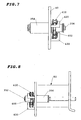
- the skewers 120-128 are removably and rotatably coupled to the front side wall 40 and the rear side wall 50, utilizing the grooves 160-172 in the front side wall 40, and the apertures 260-272 in the rear side wall 50. Since the structure of the skewers 120-128 are identical to one another, only the structure of the skewer 120 will be described in detail for purposes of simplicity.
- the skewer 120 is configured to hold food (not shown) thereon.
- the skewer 120 includes a shaft 450, a handle 460, and a sprocket 462.
- the shaft 450 has a first end 468 and a second end 470.
- the sprocket 462 of the skewer 120 is disposed on the shaft 450 a predetermined distance from the first end 468 of the shaft 450.
- the handle 460 is coupled to the first end 468 of the shaft 450.
- the skewer 120 is configured to be rotatably and removably coupled to the front side wall 40 in the rear side wall 50 such that a portion of the shaft 450 between the sprocket 462 and the handle 460 is rotatably disposed in the groove 160 of the front side wall 40, and the second end 470 of the shaft 450 extends through the aperture 260 (shown in FIG. 3 ) of the rear side wall 50, and the sprocket 462 of the skewer 120 is disposed in the interior region 72.
- the teeth of the sprocket 462 of the skewer 120 are operationally and removably coupled to the chain 410 such that movement of the chain 410 in a first direction rotates the skewer 120 in a first rotational direction, and movement of the chain 410 in a second direction rotates the skewer 120 in a second rotational direction.
- a ratio of a number of teeth of the sprocket 462 of the skewer 120 and a number of teeth of the drive sprocket 400 is greater than 1.25.
- the sprocket 462 has 14 teeth and the sprocket 400 has 9 teeth.
- the sprockets 462 and 400 could have varying numbers of teeth depending on the desired rotational speed of the skewers 120-128.
- the skewer 120 has optional accessories including the plates 500, 502 and the tines 504, 506.
- the plates 500, 502 are removably coupled to the shaft 450.
- the tines 504, 506 can be utilized to pierce relatively large pieces of food which are coupled to the skewer 120.
- the plate 500 includes apertures 521, 522, 523 extending therethrough.
- the plate 502 includes apertures 531, 532, 533 extending therethrough.
- the apertures 521, 531 are sized and shaped to receive the shaft 450 therethrough such that the plates 500, 502 to rotate with the shaft 450.
- the tine 504 extends through the apertures 522, 532 such that the plates 500, 502 support the tine 504 thereon.
- the electric motor 140 is configured to be removably coupled to the motor mounting bracket 80.
- the electric motor 140 includes a pin 541 that is configured to be received within the groove 330 of the motor mounting bracket 80.
- the electric motor 140 is further configured to rotate the drive shaft 352 for rotating sprockets 400, 402 and moving the chain 410.
- the electric motor 140 is battery powered. In an alternative embodiment, the electric motor 140 is powered via an electrical cord (not shown).
- the top cover plate 142 is configured to be slidably disposed on the left side wall 60 and the right side wall 70.
- the top cover plate 142 includes a plate portion 550, flange portions 552, 554, and a handle member 555.
- the flange portions 552, 554 are disposed on opposite ends of the plate portion 550.
- the plate portion 550 is configured to be disposed on at least on the left side wall 60 and the right side wall 70, and the flange portions 552, 554 are disposed proximate to outer sides of the left side wall 60 and the right side wall 70, respectively.
- the handle member 555 is coupled to the plate portion 550 is configured to allow an operator to easily position the top cover plate 142 at desired locations.
- the heat directing plates 30, 32 can be positioned on the grill 10 to direct heat from the grill 10 into the interior region of the cooking assembly 20.
- the cooking assembly 20 optionally includes the legs 144, 145, 146, 147 for supporting the remainder of the cooking assembly 20 at a desired height.
- the legs 144, 145 are coupled to the left side wall 60.
- the legs 146, 147 are coupled to the right side wall 70. Since the structure of the legs 144-147 are identical to one another only the structure of the leg 144 will be described in further detail below for purposes of simplicity.
- the leg 144 has a tubular shaft 560, a positioning pin 570, a bolt 580, and a nut 582.
- the tubular shaft 560 has an aperture extending therethrough.
- the positioning pin 570 is coupled to an exterior surface of the tubular shaft 560 and is configured to be received in the aperture 290 (shown in FIG. 3 ) of the left side wall 60.
- the bolt 580 is configured to be received through the aperture of the tubular shaft 560 and the aperture 292 (shown in FIG. 3 ) in the left side wall 60 to couple the leg 144 to the left side wall 60.
- the cooking assembly 20 can further include a fire box 148 that is coupled to the left side wall 60 and the right side wall 70.
- the fire box 148 is configured to hold charcoal or other flammable materials therein.
- the fire box 148 includes side walls 600, 602, 604, 606 and a bottom wall 608 which form an interior region 609 for holding the charcoal or other flammable materials therein.
- the side wall 604 includes apertures 620, 622 extending therethrough for receiving respective bolts therethrough for coupling the side wall 604 to the left side wall 60.
- the bolts that are utilized to couple the legs 144, 145 to the left side wall 60 are also utilized to couple the side wall 604 of the fire box 148 to the left side wall 60.
- the side wall 606 includes apertures 624, 626 extending therethrough for receiving respective bolts therethrough for coupling the side wall 606 to the right side wall 70.
- the bolts that are utilized to couple the legs 146, 147 to the right side wall 70 are also utilized to couple the side wall 606 of the fire box 148 to the right side wall 70.
- the cooking assembly disclosed herein provides a substantial advantage over other cooking assemblies.
- the cooking assembly provides a technical effect of utilizing a compact chain drive assembly that is mounted on a front side wall within an interior region of the assembly and thus is safer to use than other assemblies.
- the cooking assembly utilizes upper and lower chain support members which allow a relatively long chain in an interior region of the cooking assembly to be driven only by two sprockets.
Landscapes
- Engineering & Computer Science (AREA)
- Food Science & Technology (AREA)
- Baking, Grill, Roasting (AREA)
Claims (11)
- Kocheinheit mit einer ersten, zweiten, dritten und vierten Seitenwand (40, 50, 60, 70), einen Spieß (120) und einer Kettenantriebsanordnung (110); wobei die erste, zweite, dritte und vierte Seitenwand (40, 50, 60, 70) einen Innenraum (72) dazwischen bilden, wobei der Innenraum (72) so bemessen ist, um Lebensmittel darin aufzunehmen; wobei die erste und die zweite Seitenwand (40, 50) im Wesentlichen parallel und voneinander beabstandet sind, wobei die dritte und vierte Seitenwand (60, 70) im Wesentlichen parallel und voneinander beabstandet sind, wobei die erste Seitenwand (40) mit der dritten und vierten Seitenwand (60, 70) verbunden ist, wobei die zweite Seitenwand (50) mit der dritten und vierten Seitenwand (60, 70) verbunden ist, wobei die erste Seitenwand (40) eine erste Nut (160) darin aufweist, und die zweite Seitenwand (50) eine erste Öffnung (260) aufweist, welche sich durch dieselbe erstreckt, wobei der Spieß (120) eine Welle (450), einen Griff (460) und einen Ritzel (462) aufweist; wobei die Welle (450) ein erstes und ein zweites Ende (468, 470) aufweist, wobei der Ritzel (462) des Spießes (120) auf der Welle (450) an einem vorbestimmten Abstand vom ersten Ende (468) der Welle (450) angeordnet ist, wobei der Griff (460) mit dem ersten Ende (468) der Welle (450) verbunden ist, wobei der Spieß (120) drehbar und lösbar mit der ersten und zweiten Seitenwand (40, 50) verbunden ist, sodass ein Abschnitt der Welle (450) zwischen dem Ritzel (462) und dem Griff (460) in der ersten Nut (160) der ersten Seitenwand (40) drehbar angeordnet ist, und das zweite Ende (470) der Welle (450) sich durch die erste Öffnung (260) der zweiten Seitenwand (50) erstreckt; wobei die Kettenantriebsanordnung (110) einen ersten und zweiten Ritzel (400, 402), eine Kette (410), und eine erste und zweite Welle (352, 356) aufweist, wobei der erste und zweite Ritzel (400, 402) jeweils drehbar mit der ersten und zweiten Welle (352, 356) verbunden sind, wobei der erste und zweite Ritzel (400, 402) zum Bewegen der Kette (410) konfiguriert sind, sodass die Kette (410) den Ritzel (462) des Spießes (120) dreht, gekennzeichnet durch:die zweite, dritte und vierte Seitenwand (50, 60, 70) im Wesentlichen die gleiche Höhe untereinander aufweisen, und die Höhe der ersten Seitenwand (40) kleiner als die jeweilige Höhe der zweiten, dritten und vierten Seitenwand (50, 60, 70) ist;eine obere Deckplatte (142), welche konfiguriert ist, um gleitend auf der dritten und vierten Seitenwand (60, 70) angeordnet zu sein, sodass ein Spalt (74) zwischen der oberen Deckplatte (142) und der ersten Seitenwand (40) gebildet ist;der Ritzel (462) des Spießes (120) im zum Aufnehmen von Lebensmitteln bemessenen Innenraum (72) zwischen der ersten, zweiten, dritten und vierten Seitenwand (40, 50, 60, 70) angeordnet ist; unddie Kettenantriebsanordnung (110) ferner einen ersten und zweiten Lager (350, 354) und ein erstes und zweites L-förmiges Kettenstützglied (420, 430) aufweist;wobei der erste und zweite Ritzel (400, 402) und die Kette (410) im zum Aufnehmen von Lebensmitteln bemessenen Innenraum (72) zwischen der ersten, zweiten, dritten und vierten Seitenwand (40, 50, 60, 70) angeordnet sind;die erste und zweite Welle (352, 356) jeweils drehbar vom ersten und zweiten Lager (350, 354) getragen sind, welche mit der ersten Seitenwand (40) verbunden sind, wobei das erste und zweite L-förmige Kettenstützglied (420, 430) mit der ersten Seitenwand (40) im zum Aufnehmen von Lebensmitteln bemessenen Innenraum (72) zwischen der ersten, zweiten, dritten und vierten Seitenwand (40, 50, 60, 70) verbunden ist, wobei das erste L-förmige Kettenstützglied (420) zwischen dem ersten und zweiten Ritzel (400, 402) angeordnet und konfiguriert ist, um einen ersten Abschnitt der Kette (410) zu tragen, wobei das zweite L-förmige Kettenstützglied (430) zwischen dem ersten und zweiten Ritzel (400, 402) und unterhalb des ersten L-förmigen Kettenstützglieds (420) angeordnet ist, wobei das zweite L-förmige Kettenstützglied (430) zum Tragen eines zweiten Abschnitts der Kette (410) konfiguriert ist.
- Kocheinheit nach Anspruch 1, ferner umfassend eine Motorhalterung (80) und einen Motor (140), dadurch gekennzeichnet, dass die Motorhalterung (80) ein Rahmenglied (320) und eine Halteplatte (322) aufweist, welche mit dem ersten Ende des Rahmenglieds (320) verbunden ist, wobei die Halteplatte (322) eine sich darin erstreckende Nut (330) aufweist, wobei der Motor (140) einen Motorkupplungszapfen (541) aufweist, welcher konfiguriert ist, um lösbar innerhalb der Nut (330) aufgenommen zu werden, um den Motor (140) an der Halteplatte (322) lösbar zu befestigen, wobei das Rahmenglied (320) ein zweites Ende aufweist, welches mit der ersten Seitenwand (40) verbunden ist.
- Kocheinheit nach Anspruch 2, dadurch gekennzeichnet, dass der Motor (140) ferner mit der ersten Welle (352) verbunden ist, welche sich durch eine Öffnung in der ersten Seitenwand (40) und durch eine Öffnung (324) in der Motorhalterung (80) erstreckt, wobei der Motor (140) ferner zum Drehen der ersten Welle (352) konfiguriert ist.
- Kocheinheit nach Anspruch 1, ferner umfassend einen Feuerkorb (148), dadurch gekennzeichnet, dass der Feuerkorb (148) zumindest mit der dritten und vierten Seitenwand (60, 70) verbunden ist und sich unterhalb der ersten, zweiten, dritten und vierten Seitenwand (40, 50, 60, 70) erstreckt.
- Kocheinheit nach Anspruch 1, dadurch gekennzeichnet, dass der Spieß (120) ferner eine erste und zweite Platte (500, 502) und einen Zinken (504) umfasst, wobei die erste Platte (500) eine erste und zweite sich durch dieselbe erstreckende Öffnung (521, 522) aufweist, wobei die zweite Platte (502) eine dritte und vierte sich durch dieselbe erstreckende Öffnung (531, 532) aufweist, wobei die Welle (450) in der ersten und dritten Öffnung (521, 531) lösbar angeordnet ist, wobei der Zinken (504) in der zweiten und vierten Öffnung (522, 532) lösbar angeordnet ist.
- Kocheinheit nach Anspruch 1, ferner umfassend einen ersten Schenkel (144), welcher mit der dritten Seitenwand (60) verbunden ist, dadurch gekennzeichnet, dass der erste Schenkel (144) einen Rohrschaft (560), einen Positionierzapfen (570), und einen Bolzen (580) aufweist; wobei der Rohrschaft (560) eine sich durch denselben erstreckenden Öffnung aufweist, wobei der Positionierzapfen (570) mit einer Außenfläche des Rohrschafts (560) verbunden und konfiguriert ist, um in einer Öffnung (290) der dritten Seitenwand (60) aufgenommen zu werden, wobei der Bolzen konfiguriert ist, um durch die Öffnung des Rohrschafts (560) und die Öffnung (292) in der dritten Seitenwand (60) aufgenommen zu werden, um den ersten Schenkel (144) mit der dritten Seitenwand (60) zu verbinden.
- Kocheinheit nach Anspruch 1, dadurch gekennzeichnet, dass die Kettenantriebsanordnung (110) nur mit der ersten Seitenwand (40) und nicht mit der zweiten, dritten und vierten Seitenwand (50, 60, 70) verbunden ist.
- Kocheinheit nach Anspruch 1, ferner umfassend eine Wärmeleitplatte (30), dadurch gekennzeichnet, dass die Wärmeleitplatte (30) konfiguriert ist, um auf einer Oberfläche eines Rosts (10) in der Nähe zumindest einer der zweiten, dritten und vierten Seitenwand (50, 60, 70) angeordnet zu werden, um Wärme in den Innenraum (72) zu leiten.
- Kocheinheit nach Anspruch 1, dadurch gekennzeichnet, dass das Verhältnis zwischen der Anzahl von Zähnen des Ritzels (462) des Spießes (120) und der Anzahl von Zähnen des ersten Ritzels (400) größer als 1,25 ist.
- Kocheinheit nach Anspruch 1, dadurch gekennzeichnet, dass das erste L-förmige Kettenstützglied (420) einen ersten und zweiten Abschnitt aufweist, wobei der erste Abschnitt sich im Wesentlichen senkrecht zur ersten Seitenwand (40) erstreckt und ein erstes Ende aufweist, welches mit der ersten Seitenwand (40) verbunden ist, wobei der zweite Abschnitt mit einem zweiten Ende des ersten Abschnitts verbunden ist und sich im Wesentlichen senkrecht zum ersten Abschnitt erstreckt.
- Kocheinheit nach Anspruch 1, dadurch gekennzeichnet, dass die Länge des ersten L-förmigen Kettenstützglieds (420) zumindest 80% der horizontalen Länge der ersten Seitenwand (40) entspricht.
Applications Claiming Priority (2)
| Application Number | Priority Date | Filing Date | Title |
|---|---|---|---|
| US13/843,665 US10010215B2 (en) | 2013-03-15 | 2013-03-15 | Cooking assembly |
| PCT/IB2014/059124 WO2014140967A1 (en) | 2013-03-15 | 2014-02-20 | Cooking assembly |
Publications (2)
| Publication Number | Publication Date |
|---|---|
| EP2967256A1 EP2967256A1 (de) | 2016-01-20 |
| EP2967256B1 true EP2967256B1 (de) | 2017-03-29 |
Family
ID=50349665
Family Applications (1)
| Application Number | Title | Priority Date | Filing Date |
|---|---|---|---|
| EP14712349.1A Not-in-force EP2967256B1 (de) | 2013-03-15 | 2014-02-20 | Kochvorrichtung |
Country Status (5)
| Country | Link |
|---|---|
| US (1) | US10010215B2 (de) |
| EP (1) | EP2967256B1 (de) |
| AU (1) | AU2014229446B2 (de) |
| CA (1) | CA2980442A1 (de) |
| WO (1) | WO2014140967A1 (de) |
Families Citing this family (8)
| Publication number | Priority date | Publication date | Assignee | Title |
|---|---|---|---|---|
| ES1157533Y (es) * | 2016-04-25 | 2016-08-22 | Llop Ricard Prats | Barbacoa con parrillas independientes y moviles |
| US20170332840A1 (en) * | 2016-05-19 | 2017-11-23 | Leopard Industries, Inc. | Cooktop Insert |
| KR102032692B1 (ko) * | 2016-11-14 | 2019-10-15 | 오지영 | 휴대용 꼬치 구이장치 |
| US10765263B2 (en) * | 2017-01-25 | 2020-09-08 | Jay Paul Grooten | Food skewer |
| KR101894373B1 (ko) * | 2018-04-11 | 2018-09-04 | 강용훈 | 캠핑용 화로대에 사용될 수 있는 오토 바비큐 장치 |
| US20200288910A1 (en) * | 2019-03-12 | 2020-09-17 | Kudu Safari Braai, Llc | Rotisserie assemblies and methods of making and using the same |
| US11659843B2 (en) | 2019-11-12 | 2023-05-30 | Fabrice Marcy Andre-Bartley | Food smoking skewer |
| US11490763B2 (en) * | 2020-04-14 | 2022-11-08 | Jilong Wu | Fully automatic and efficiently energy-saving barbecue grill |
Family Cites Families (17)
| Publication number | Priority date | Publication date | Assignee | Title |
|---|---|---|---|---|
| US2939384A (en) | 1958-11-17 | 1960-06-07 | Laurell H Vinson | Collapsible grill for spit of brazier |
| US3169470A (en) | 1960-12-13 | 1965-02-16 | Oatley Arthur Frederick | Multiple skewer attachment for a broiler |
| US3939761A (en) | 1972-05-01 | 1976-02-24 | Mcginty Clarence E | Barbecue rotisserie apparatus |
| US4154154A (en) | 1976-06-01 | 1979-05-15 | Vivian Weldon B | Skewered food cooking devices |
| US4176592A (en) * | 1978-03-10 | 1979-12-04 | Doyle Charles E Jr | Skewer |
| US4760776A (en) | 1986-07-25 | 1988-08-02 | Donald Beidler | Mobil barbeque cart |
| US5001971A (en) | 1990-05-15 | 1991-03-26 | Belson Manufacturing Co., Inc. | Shish kabob rotisserie |
| US5172628A (en) | 1991-06-03 | 1992-12-22 | Pillsbury Thomas J | Rotary food cooking device for a grill |
| CA2162144C (fr) | 1993-04-22 | 2004-10-19 | Jean Noel Coutant | Tourne-brochettes automatique |
| US5649475A (en) | 1995-08-11 | 1997-07-22 | W.C. Bradley Company | Universal rotisserie assembly |
| US5960706A (en) | 1998-09-21 | 1999-10-05 | Cheng; Wen-Ho | Meat string rotating device for barbecues |
| US6837151B2 (en) | 2002-10-23 | 2005-01-04 | Shane Chen | Convertible rotisserie/kebab cooking device |
| WO2007056871A1 (de) | 2005-11-15 | 2007-05-24 | Rüegg Cheminee Ag | Vorrichtung zum grillen von speisen |
| US8079302B2 (en) * | 2008-10-15 | 2011-12-20 | Steven Giangrasso | Portable cooking unit |
| US8122817B2 (en) * | 2008-11-19 | 2012-02-28 | Ilia Nimerovskiy | Rotisserie roto-robot kit for programmable skewer rotation |
| US9038620B2 (en) * | 2011-06-17 | 2015-05-26 | Lawrence Stephen Brown | Convertible mobile fire pit and cooker assembly |
| CA2793781C (en) * | 2011-11-21 | 2015-11-17 | Jonathan D. George | Barbecue and barbecue accessory for flare up prevention, and improved temperature distribution and heat retention |
-
2013
- 2013-03-15 US US13/843,665 patent/US10010215B2/en active Active
-
2014
- 2014-02-20 CA CA2980442A patent/CA2980442A1/en not_active Abandoned
- 2014-02-20 WO PCT/IB2014/059124 patent/WO2014140967A1/en not_active Ceased
- 2014-02-20 AU AU2014229446A patent/AU2014229446B2/en not_active Ceased
- 2014-02-20 EP EP14712349.1A patent/EP2967256B1/de not_active Not-in-force
Non-Patent Citations (1)
| Title |
|---|
| None * |
Also Published As
| Publication number | Publication date |
|---|---|
| AU2014229446A1 (en) | 2015-09-24 |
| CA2980442A1 (en) | 2014-09-18 |
| WO2014140967A1 (en) | 2014-09-18 |
| AU2014229446B2 (en) | 2016-04-21 |
| US20140261013A1 (en) | 2014-09-18 |
| US10010215B2 (en) | 2018-07-03 |
| EP2967256A1 (de) | 2016-01-20 |
Similar Documents
| Publication | Publication Date | Title |
|---|---|---|
| EP2967256B1 (de) | Kochvorrichtung | |
| US8485176B2 (en) | Cooking apparatus with adjustable fuel support | |
| US3939761A (en) | Barbecue rotisserie apparatus | |
| US20120285338A1 (en) | Attachment to barbeque grill | |
| US3335712A (en) | Charcoal broiler | |
| JP2015092969A (ja) | バーベキューグリルボックス | |
| KR200470999Y1 (ko) | 바비큐 구이용 원통형 석쇠 | |
| CN202005637U (zh) | 自动翻转可卸签烧烤炉 | |
| CA2793781C (en) | Barbecue and barbecue accessory for flare up prevention, and improved temperature distribution and heat retention | |
| US20160120361A1 (en) | Smokeless Barbecue Device | |
| US2122780A (en) | Rotary cooking appliance | |
| US20060144249A1 (en) | Barbecue grill having rotatable tools | |
| JP3148554U (ja) | グリル装置及び鳥肉等の自動炭火焼き機 | |
| KR200494945Y1 (ko) | 꼬치구이 장치 | |
| KR101888038B1 (ko) | 꼬치구이장치 | |
| KR200400383Y1 (ko) | 꼬치구이 장치 | |
| KR102111257B1 (ko) | 꼬치구이기 | |
| KR101522827B1 (ko) | 조립식 꼬치구이 장치 | |
| KR101519722B1 (ko) | 휴대용 숯불구이 장치 | |
| KR20120007809U (ko) | 회전 구이기 | |
| CN101422328B (zh) | 可更改组态的烧烤烹饪器具 | |
| CN109528021B (zh) | 一种自动烧烤炒菜机 | |
| KR200473888Y1 (ko) | 조립식 바베큐 장치 | |
| KR101105723B1 (ko) | 그릴거치대를 구비하는 바비큐장치 | |
| KR200395371Y1 (ko) | 꼬치 구이기 |
Legal Events
| Date | Code | Title | Description |
|---|---|---|---|
| PUAI | Public reference made under article 153(3) epc to a published international application that has entered the european phase |
Free format text: ORIGINAL CODE: 0009012 |
|
| 17P | Request for examination filed |
Effective date: 20150930 |
|
| AK | Designated contracting states |
Kind code of ref document: A1 Designated state(s): AL AT BE BG CH CY CZ DE DK EE ES FI FR GB GR HR HU IE IS IT LI LT LU LV MC MK MT NL NO PL PT RO RS SE SI SK SM TR |
|
| AX | Request for extension of the european patent |
Extension state: BA ME |
|
| DAX | Request for extension of the european patent (deleted) | ||
| GRAP | Despatch of communication of intention to grant a patent |
Free format text: ORIGINAL CODE: EPIDOSNIGR1 |
|
| INTG | Intention to grant announced |
Effective date: 20160824 |
|
| GRAS | Grant fee paid |
Free format text: ORIGINAL CODE: EPIDOSNIGR3 |
|
| GRAJ | Information related to disapproval of communication of intention to grant by the applicant or resumption of examination proceedings by the epo deleted |
Free format text: ORIGINAL CODE: EPIDOSDIGR1 |
|
| GRAL | Information related to payment of fee for publishing/printing deleted |
Free format text: ORIGINAL CODE: EPIDOSDIGR3 |
|
| GRAP | Despatch of communication of intention to grant a patent |
Free format text: ORIGINAL CODE: EPIDOSNIGR1 |
|
| INTG | Intention to grant announced |
Effective date: 20160824 |
|
| INTC | Intention to grant announced (deleted) | ||
| INTG | Intention to grant announced |
Effective date: 20170124 |
|
| GRAA | (expected) grant |
Free format text: ORIGINAL CODE: 0009210 |
|
| AK | Designated contracting states |
Kind code of ref document: B1 Designated state(s): AL AT BE BG CH CY CZ DE DK EE ES FI FR GB GR HR HU IE IS IT LI LT LU LV MC MK MT NL NO PL PT RO RS SE SI SK SM TR |
|
| REG | Reference to a national code |
Ref country code: GB Ref legal event code: FG4D |
|
| REG | Reference to a national code |
Ref country code: CH Ref legal event code: EP |
|
| REG | Reference to a national code |
Ref country code: AT Ref legal event code: REF Ref document number: 878967 Country of ref document: AT Kind code of ref document: T Effective date: 20170415 |
|
| REG | Reference to a national code |
Ref country code: IE Ref legal event code: FG4D |
|
| REG | Reference to a national code |
Ref country code: DE Ref legal event code: R096 Ref document number: 602014008097 Country of ref document: DE |
|
| PG25 | Lapsed in a contracting state [announced via postgrant information from national office to epo] |
Ref country code: HR Free format text: LAPSE BECAUSE OF FAILURE TO SUBMIT A TRANSLATION OF THE DESCRIPTION OR TO PAY THE FEE WITHIN THE PRESCRIBED TIME-LIMIT Effective date: 20170329 Ref country code: GR Free format text: LAPSE BECAUSE OF FAILURE TO SUBMIT A TRANSLATION OF THE DESCRIPTION OR TO PAY THE FEE WITHIN THE PRESCRIBED TIME-LIMIT Effective date: 20170630 Ref country code: FI Free format text: LAPSE BECAUSE OF FAILURE TO SUBMIT A TRANSLATION OF THE DESCRIPTION OR TO PAY THE FEE WITHIN THE PRESCRIBED TIME-LIMIT Effective date: 20170329 Ref country code: NO Free format text: LAPSE BECAUSE OF FAILURE TO SUBMIT A TRANSLATION OF THE DESCRIPTION OR TO PAY THE FEE WITHIN THE PRESCRIBED TIME-LIMIT Effective date: 20170629 Ref country code: LT Free format text: LAPSE BECAUSE OF FAILURE TO SUBMIT A TRANSLATION OF THE DESCRIPTION OR TO PAY THE FEE WITHIN THE PRESCRIBED TIME-LIMIT Effective date: 20170329 |
|
| REG | Reference to a national code |
Ref country code: NL Ref legal event code: MP Effective date: 20170329 |
|
| REG | Reference to a national code |
Ref country code: AT Ref legal event code: MK05 Ref document number: 878967 Country of ref document: AT Kind code of ref document: T Effective date: 20170329 |
|
| PG25 | Lapsed in a contracting state [announced via postgrant information from national office to epo] |
Ref country code: RS Free format text: LAPSE BECAUSE OF FAILURE TO SUBMIT A TRANSLATION OF THE DESCRIPTION OR TO PAY THE FEE WITHIN THE PRESCRIBED TIME-LIMIT Effective date: 20170329 Ref country code: SE Free format text: LAPSE BECAUSE OF FAILURE TO SUBMIT A TRANSLATION OF THE DESCRIPTION OR TO PAY THE FEE WITHIN THE PRESCRIBED TIME-LIMIT Effective date: 20170329 Ref country code: BG Free format text: LAPSE BECAUSE OF FAILURE TO SUBMIT A TRANSLATION OF THE DESCRIPTION OR TO PAY THE FEE WITHIN THE PRESCRIBED TIME-LIMIT Effective date: 20170629 Ref country code: LV Free format text: LAPSE BECAUSE OF FAILURE TO SUBMIT A TRANSLATION OF THE DESCRIPTION OR TO PAY THE FEE WITHIN THE PRESCRIBED TIME-LIMIT Effective date: 20170329 |
|
| PG25 | Lapsed in a contracting state [announced via postgrant information from national office to epo] |
Ref country code: NL Free format text: LAPSE BECAUSE OF FAILURE TO SUBMIT A TRANSLATION OF THE DESCRIPTION OR TO PAY THE FEE WITHIN THE PRESCRIBED TIME-LIMIT Effective date: 20170329 |
|
| PG25 | Lapsed in a contracting state [announced via postgrant information from national office to epo] |
Ref country code: CZ Free format text: LAPSE BECAUSE OF FAILURE TO SUBMIT A TRANSLATION OF THE DESCRIPTION OR TO PAY THE FEE WITHIN THE PRESCRIBED TIME-LIMIT Effective date: 20170329 Ref country code: AT Free format text: LAPSE BECAUSE OF FAILURE TO SUBMIT A TRANSLATION OF THE DESCRIPTION OR TO PAY THE FEE WITHIN THE PRESCRIBED TIME-LIMIT Effective date: 20170329 Ref country code: RO Free format text: LAPSE BECAUSE OF FAILURE TO SUBMIT A TRANSLATION OF THE DESCRIPTION OR TO PAY THE FEE WITHIN THE PRESCRIBED TIME-LIMIT Effective date: 20170329 Ref country code: EE Free format text: LAPSE BECAUSE OF FAILURE TO SUBMIT A TRANSLATION OF THE DESCRIPTION OR TO PAY THE FEE WITHIN THE PRESCRIBED TIME-LIMIT Effective date: 20170329 Ref country code: ES Free format text: LAPSE BECAUSE OF FAILURE TO SUBMIT A TRANSLATION OF THE DESCRIPTION OR TO PAY THE FEE WITHIN THE PRESCRIBED TIME-LIMIT Effective date: 20170329 Ref country code: SK Free format text: LAPSE BECAUSE OF FAILURE TO SUBMIT A TRANSLATION OF THE DESCRIPTION OR TO PAY THE FEE WITHIN THE PRESCRIBED TIME-LIMIT Effective date: 20170329 |
|
| PG25 | Lapsed in a contracting state [announced via postgrant information from national office to epo] |
Ref country code: SM Free format text: LAPSE BECAUSE OF FAILURE TO SUBMIT A TRANSLATION OF THE DESCRIPTION OR TO PAY THE FEE WITHIN THE PRESCRIBED TIME-LIMIT Effective date: 20170329 Ref country code: IS Free format text: LAPSE BECAUSE OF FAILURE TO SUBMIT A TRANSLATION OF THE DESCRIPTION OR TO PAY THE FEE WITHIN THE PRESCRIBED TIME-LIMIT Effective date: 20170729 Ref country code: PL Free format text: LAPSE BECAUSE OF FAILURE TO SUBMIT A TRANSLATION OF THE DESCRIPTION OR TO PAY THE FEE WITHIN THE PRESCRIBED TIME-LIMIT Effective date: 20170329 |
|
| REG | Reference to a national code |
Ref country code: DE Ref legal event code: R097 Ref document number: 602014008097 Country of ref document: DE |
|
| PG25 | Lapsed in a contracting state [announced via postgrant information from national office to epo] |
Ref country code: DK Free format text: LAPSE BECAUSE OF FAILURE TO SUBMIT A TRANSLATION OF THE DESCRIPTION OR TO PAY THE FEE WITHIN THE PRESCRIBED TIME-LIMIT Effective date: 20170329 |
|
| PLBE | No opposition filed within time limit |
Free format text: ORIGINAL CODE: 0009261 |
|
| STAA | Information on the status of an ep patent application or granted ep patent |
Free format text: STATUS: NO OPPOSITION FILED WITHIN TIME LIMIT |
|
| REG | Reference to a national code |
Ref country code: FR Ref legal event code: PLFP Year of fee payment: 5 |
|
| PG25 | Lapsed in a contracting state [announced via postgrant information from national office to epo] |
Ref country code: IT Free format text: LAPSE BECAUSE OF FAILURE TO SUBMIT A TRANSLATION OF THE DESCRIPTION OR TO PAY THE FEE WITHIN THE PRESCRIBED TIME-LIMIT Effective date: 20170329 |
|
| 26N | No opposition filed |
Effective date: 20180103 |
|
| PG25 | Lapsed in a contracting state [announced via postgrant information from national office to epo] |
Ref country code: SI Free format text: LAPSE BECAUSE OF FAILURE TO SUBMIT A TRANSLATION OF THE DESCRIPTION OR TO PAY THE FEE WITHIN THE PRESCRIBED TIME-LIMIT Effective date: 20170329 |
|
| REG | Reference to a national code |
Ref country code: CH Ref legal event code: PL |
|
| PG25 | Lapsed in a contracting state [announced via postgrant information from national office to epo] |
Ref country code: MC Free format text: LAPSE BECAUSE OF FAILURE TO SUBMIT A TRANSLATION OF THE DESCRIPTION OR TO PAY THE FEE WITHIN THE PRESCRIBED TIME-LIMIT Effective date: 20170329 |
|
| REG | Reference to a national code |
Ref country code: IE Ref legal event code: MM4A |
|
| REG | Reference to a national code |
Ref country code: BE Ref legal event code: MM Effective date: 20180228 |
|
| PG25 | Lapsed in a contracting state [announced via postgrant information from national office to epo] |
Ref country code: CH Free format text: LAPSE BECAUSE OF NON-PAYMENT OF DUE FEES Effective date: 20180228 Ref country code: LU Free format text: LAPSE BECAUSE OF NON-PAYMENT OF DUE FEES Effective date: 20180220 Ref country code: LI Free format text: LAPSE BECAUSE OF NON-PAYMENT OF DUE FEES Effective date: 20180228 |
|
| PG25 | Lapsed in a contracting state [announced via postgrant information from national office to epo] |
Ref country code: IE Free format text: LAPSE BECAUSE OF NON-PAYMENT OF DUE FEES Effective date: 20180220 |
|
| PG25 | Lapsed in a contracting state [announced via postgrant information from national office to epo] |
Ref country code: BE Free format text: LAPSE BECAUSE OF NON-PAYMENT OF DUE FEES Effective date: 20180228 |
|
| PG25 | Lapsed in a contracting state [announced via postgrant information from national office to epo] |
Ref country code: MT Free format text: LAPSE BECAUSE OF NON-PAYMENT OF DUE FEES Effective date: 20180220 |
|
| PG25 | Lapsed in a contracting state [announced via postgrant information from national office to epo] |
Ref country code: TR Free format text: LAPSE BECAUSE OF FAILURE TO SUBMIT A TRANSLATION OF THE DESCRIPTION OR TO PAY THE FEE WITHIN THE PRESCRIBED TIME-LIMIT Effective date: 20170329 |
|
| PG25 | Lapsed in a contracting state [announced via postgrant information from national office to epo] |
Ref country code: PT Free format text: LAPSE BECAUSE OF FAILURE TO SUBMIT A TRANSLATION OF THE DESCRIPTION OR TO PAY THE FEE WITHIN THE PRESCRIBED TIME-LIMIT Effective date: 20170329 |
|
| PG25 | Lapsed in a contracting state [announced via postgrant information from national office to epo] |
Ref country code: CY Free format text: LAPSE BECAUSE OF FAILURE TO SUBMIT A TRANSLATION OF THE DESCRIPTION OR TO PAY THE FEE WITHIN THE PRESCRIBED TIME-LIMIT Effective date: 20170329 Ref country code: MK Free format text: LAPSE BECAUSE OF NON-PAYMENT OF DUE FEES Effective date: 20170329 Ref country code: HU Free format text: LAPSE BECAUSE OF FAILURE TO SUBMIT A TRANSLATION OF THE DESCRIPTION OR TO PAY THE FEE WITHIN THE PRESCRIBED TIME-LIMIT; INVALID AB INITIO Effective date: 20140220 |
|
| PG25 | Lapsed in a contracting state [announced via postgrant information from national office to epo] |
Ref country code: AL Free format text: LAPSE BECAUSE OF FAILURE TO SUBMIT A TRANSLATION OF THE DESCRIPTION OR TO PAY THE FEE WITHIN THE PRESCRIBED TIME-LIMIT Effective date: 20170329 |
|
| PGFP | Annual fee paid to national office [announced via postgrant information from national office to epo] |
Ref country code: FR Payment date: 20210214 Year of fee payment: 8 |
|
| PGFP | Annual fee paid to national office [announced via postgrant information from national office to epo] |
Ref country code: DE Payment date: 20210323 Year of fee payment: 8 Ref country code: GB Payment date: 20210210 Year of fee payment: 8 |
|
| REG | Reference to a national code |
Ref country code: DE Ref legal event code: R119 Ref document number: 602014008097 Country of ref document: DE |
|
| GBPC | Gb: european patent ceased through non-payment of renewal fee |
Effective date: 20220220 |
|
| PG25 | Lapsed in a contracting state [announced via postgrant information from national office to epo] |
Ref country code: FR Free format text: LAPSE BECAUSE OF NON-PAYMENT OF DUE FEES Effective date: 20220228 |
|
| PG25 | Lapsed in a contracting state [announced via postgrant information from national office to epo] |
Ref country code: GB Free format text: LAPSE BECAUSE OF NON-PAYMENT OF DUE FEES Effective date: 20220220 Ref country code: DE Free format text: LAPSE BECAUSE OF NON-PAYMENT OF DUE FEES Effective date: 20220901 |