EP2965787A1 - Rapid pressure diffusion actuator for a fire extinguisher - Google Patents
Rapid pressure diffusion actuator for a fire extinguisher Download PDFInfo
- Publication number
- EP2965787A1 EP2965787A1 EP15175180.7A EP15175180A EP2965787A1 EP 2965787 A1 EP2965787 A1 EP 2965787A1 EP 15175180 A EP15175180 A EP 15175180A EP 2965787 A1 EP2965787 A1 EP 2965787A1
- Authority
- EP
- European Patent Office
- Prior art keywords
- fire extinguisher
- pressure
- container
- burst disc
- cutter
- Prior art date
- Legal status (The legal status is an assumption and is not a legal conclusion. Google has not performed a legal analysis and makes no representation as to the accuracy of the status listed.)
- Withdrawn
Links
Images


Classifications
-
- A—HUMAN NECESSITIES
- A62—LIFE-SAVING; FIRE-FIGHTING
- A62C—FIRE-FIGHTING
- A62C37/00—Control of fire-fighting equipment
- A62C37/36—Control of fire-fighting equipment an actuating signal being generated by a sensor separate from an outlet device
- A62C37/46—Construction of the actuator
-
- A—HUMAN NECESSITIES
- A62—LIFE-SAVING; FIRE-FIGHTING
- A62C—FIRE-FIGHTING
- A62C13/00—Portable extinguishers which are permanently pressurised or pressurised immediately before use
- A62C13/62—Portable extinguishers which are permanently pressurised or pressurised immediately before use with a single permanently pressurised container
- A62C13/64—Portable extinguishers which are permanently pressurised or pressurised immediately before use with a single permanently pressurised container the extinguishing material being released by means of a valve
-
- A—HUMAN NECESSITIES
- A62—LIFE-SAVING; FIRE-FIGHTING
- A62C—FIRE-FIGHTING
- A62C13/00—Portable extinguishers which are permanently pressurised or pressurised immediately before use
- A62C13/66—Portable extinguishers which are permanently pressurised or pressurised immediately before use with extinguishing material and pressure gas being stored in separate containers
- A62C13/72—Portable extinguishers which are permanently pressurised or pressurised immediately before use with extinguishing material and pressure gas being stored in separate containers characterised by releasing means operating essentially simultaneously on both containers
- A62C13/74—Portable extinguishers which are permanently pressurised or pressurised immediately before use with extinguishing material and pressure gas being stored in separate containers characterised by releasing means operating essentially simultaneously on both containers the pressure gas container being pierced or broken
-
- A—HUMAN NECESSITIES
- A62—LIFE-SAVING; FIRE-FIGHTING
- A62C—FIRE-FIGHTING
- A62C3/00—Fire prevention, containment or extinguishing specially adapted for particular objects or places
- A62C3/07—Fire prevention, containment or extinguishing specially adapted for particular objects or places in vehicles, e.g. in road vehicles
- A62C3/08—Fire prevention, containment or extinguishing specially adapted for particular objects or places in vehicles, e.g. in road vehicles in aircraft
Definitions
- the subject matter disclosed herein relates to a fire extinguisher actuator. More specifically, the subject matter disclosed relates to a fire extinguisher actuator that activates the release of a fire extinguishing agent.
- hermetically sealed fire extinguishers are typically activated by direct explosive impingement energy using a pyrotechnic trigger device, such as a pyrotechnic cartridge or squib.
- a pyrotechnic trigger device such as a pyrotechnic cartridge or squib.
- the impingement energy is focused on a dome-shaped fire extinguisher outlet burst disc such that the fire extinguisher outlet burst disc will rupture as a result of the impingement.
- the fire extinguisher outlet burst disc is typically fabricated from corrosion resistant steel.
- the pyrotechnic trigger device is retained in a discharge head in such a manner that it directly faces the fire extinguisher outlet burst disc.
- the discharge head is attached to an outlet of the fire extinguisher and is typically used to direct the flow of extinguishing agent to an aircraft interface, such as plumbing or tubing, which directs the extinguishing agent to a desired location.
- a filter screen is located within the discharge head to catch any large fire extinguisher outlet burst disc fragments created as a result of the explosive impingement energy.
- pyrotechnic trigger devices can be effective; however, pyrotechnic trigger devices require special handling procedures and training that add to overall aircraft management and maintenance costs. Additionally, pyrotechnic trigger devices may have a limited expected life span and thus require periodic replacement.
- a fire extinguisher actuator assembly for a fire extinguisher.
- the fire extinguisher includes a fire extinguisher reservoir and a fire extinguisher outlet burst disc that forms a discharge barrier between the fire extinguisher reservoir and a discharge head to retain a pressurized fire extinguishing agent at an internal fire extinguisher pressure within the fire extinguisher reservoir.
- the fire extinguisher actuator assembly includes a cutter detained within the fire extinguisher proximate the fire extinguisher outlet burst disc.
- the fire extinguisher actuator assembly also includes an interior container within the fire extinguisher reservoir, the interior container having a container pressure and sealed with a container burst disc.
- the fire extinguisher actuator assembly further includes an activation device having a piercing member. The activation device is operable to pierce the container burst disc and diffuse the container pressure to create a pressure differential relative to the internal fire extinguisher pressure at the cutter, thereby driving the cutter through the fire extinguisher outlet burst disc to release the pressurized fire extinguishing agent through the discharge head.
- a method of installing a fire extinguisher actuator assembly in a fire extinguisher includes a fire extinguisher reservoir and a fire extinguisher outlet burst disc that forms a discharge barrier between the fire extinguisher reservoir and a discharge head to retain a pressurized fire extinguishing agent at an internal fire extinguisher pressure within the fire extinguisher reservoir.
- the method includes detaining a cutter within the fire extinguisher proximate the fire extinguisher outlet burst disc.
- An interior container is placed within the fire extinguisher reservoir, where the interior container has a container pressure and is sealed with a container burst disc.
- An activation device including a piercing member is positioned within the fire extinguisher.
- the activation device is operable to pierce the container burst disc and diffuse the container pressure to create a pressure differential relative to the internal fire extinguisher pressure at the cutter, thereby driving the cutter through the fire extinguisher outlet burst disc to release the pressurized fire extinguishing agent through the discharge head.
- a fire extinguisher actuator assembly for a fire extinguisher is provided that is activated without a pyrotechnic trigger device.
- the fire extinguisher actuator assembly includes a two-part activation and release of a pressurized fire extinguishing agent using an activation device in combination with a cutter driven by rapid pressure diffusion.
- the activation device pierces a container burst disc of an interior container within a fire extinguisher reservoir, where the interior container and the fire extinguisher reservoir have different pressures.
- a change in pressure upon opening the interior container causes pressure diffusion which results in a pressure differential at the cutter to drive it through a fire extinguisher outlet burst disc.
- Using a cutter to rapidly open a fire extinguisher outlet burst disc of a fire extinguisher may remove the need to include a debris screen in a discharge head of the fire extinguisher system, as loose fire extinguisher outlet burst disc fragments typically resulting from pyrotechnic trigger device ignition are no longer present.
- the fire extinguisher system 100 includes a fire extinguisher 102 and a discharge head 104.
- the fire extinguisher 102 includes a fire extinguisher reservoir 106 and a fire extinguisher outlet burst disc 108 that forms a discharge barrier between the fire extinguisher reservoir 106 and the discharge head 104 to retain a pressurized fire extinguishing agent within the fire extinguisher reservoir 106.
- the discharge head 104 can be interfaced to plumbing/tubing to direct fire extinguishing agent to a desired location, for example, within an aircraft.
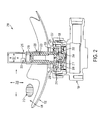
- FIG. 2 is a detailed view of a fire extinguisher actuator assembly 200 according to an embodiment.
- the fire extinguisher actuator assembly 200 includes a cutter shuttle assembly 202 having a cutter 204 coupled to a shuttle body 206.
- the cutter shuttle assembly 202 including the cutter 204 is detained within the fire extinguisher 102 proximate the fire extinguisher outlet burst disc 108 and biased to form a pressure equalization region 208 between the shuttle body 206 and the fire extinguisher outlet burst disc 108.
- the cutter shuttle assembly 202 can be detained by a plurality of flexible seals 210 until pressure from the pressure equalization region 208 is diffused.
- the flexible seals 210 also serve as detents to hold the cutter shuttle assembly 202 in place during shock and vibration such that the cutter 204 does not prematurely cut through the fire extinguisher outlet burst disc 108.
- Pressurized fire extinguishing agent 212 is held in the fire extinguisher reservoir 106 under internal fire extinguisher pressure 214.
- the shuttle body 206 includes at least one pressure equalization hole 216 ( FIG. 3 ) to establish an equilibrium pressure in the pressure equalization region 208 relative to a main interior region 218 of the fire extinguisher reservoir 106.
- the shuttle body 206 further includes at least one pressure vent hole 217 to provide a pressure diffusion path between an interior container 215 and the pressure equalization region 208.
- the interior container 215 within the fire extinguisher reservoir 106 is hermetically sealed by a container burst disc 219 to keep a container pressure 221 isolated from the internal fire extinguisher pressure 214 until the container burst disc 219 is ruptured.
- the interior container 215 may also include a pressure transducer 223 operable to monitor the container pressure 221 of the interior container 215.
- the container pressure 221 is nominally sealed at about one atmosphere of pressure (101.3 kPa) at 70 degrees F (21.1 degrees C).
- the fire extinguisher actuator assembly 200 also includes an activation device 220 having a piercing member 222 ( FIG. 4 ) that is a pointed shaft used to rupture the container burst disc 219.
- the activation device 220 is operable to pierce the container burst disc 219 and diffuse the container pressure 221 by venting the pressurized fire extinguishing agent 212 at the internal fire extinguisher pressure 214 from the pressure equalization region 208 up through the at least one pressure vent hole 217.
- the activation device 220 can be installed in the fire extinguisher reservoir 106. More particularly, the activation device 220 can be located in a container support tube 225 in the fire extinguisher reservoir 106 that mounts the interior container 215 in a fixed position.
- the activation device 220 can be electrically driven, absent a pyrotechnic trigger device.
- the activation device 220 can be a solenoid or other electro-mechanical device operable to drive the piercing member 222 ( FIG. 4 ) through the container burst disc 219.
- a support collar 227 can retain the container support tube 225 within the fire extinguisher reservoir 106.
- the support collar 227 can also serve as a detaining surface for one of the flexible seals 210 used to detain the cutter shuttle assembly 202.
- the cutter shuttle assembly 202 may also be detained by another of the flexible seals 210 installed between the shuttle body 206 and the container support tube 225.
- the shuttle body 206 may also include a ledge 229 upon which the internal fire extinguisher pressure 214 is applied from the main interior region 218 of the fire extinguisher reservoir 106. Until the activation device 220 is triggered, the pressure equalization region 208 contains pressurized fire extinguishing agent 212 at the internal fire extinguisher pressure 214.
- the internal fire extinguisher pressure 214 in the main interior region 218 overcomes the detaining force of the flexible seals 210 and drives the cutter shuttle assembly 202 toward the fire extinguisher outlet burst disc 108 where the cutter 204 cuts the fire extinguisher outlet burst disc 108 open to discharge the pressurized fire extinguishing agent 212 from the main interior region 218 of the fire extinguisher reservoir 106 out of the discharge head 104.
- the fire extinguisher actuator assembly 200 can include other structure elements to support and stabilize the interior container 215 and the activation device 220, as well as electrical connections, which are not depicted to simplify the drawings. Also, not shown for drawing simplicity, is that the shuttle body 206 is restrained internally so it cannot become a projectile if the fire extinguisher 102 is inadvertently discharged while the discharge head 104, or other protective device, is not in place at the time of the inadvertent discharge.
- the fire extinguisher reservoir 106 can be sized to accommodate a wide variety of installations.
- the fire extinguisher reservoir 106 can range in size from 40 cubic inches (655.5 cm 3 ) to 2,500+ cubic inches (40,968+ cm 3 ). Pressure changes within the fire extinguisher reservoir 106 can occur due to ambient temperature variations. For example, in an aircraft environment, the fire extinguisher 102 may be at 240 degrees F (115.6 degrees C) on the ground on a hot day and after takeoff be at -65 degrees F (-53.9 degrees C) at altitude. These temperature changes cause substantial changes to the internal fire extinguisher pressure 214. As changes occur to the internal fire extinguisher pressure 214, pressure equalization holes 216 ( FIG.
- Example nominal pressure values of the internal fire extinguisher pressure 214 can range from between about 300 pounds-per-square-inch (2,068 kPa) to about 800 pounds-per-square-inch (5,515 kPa) at 70 degrees F (21.1 degrees C), with higher pressures at higher temperatures and lower pressures at lower temperatures.
- a volume-pressure equation (equation 1) can be used to calculate pressure values when the volume of the interior container 215 and the combined volume of the container support tube 225 and pressure equalization region 208 are known.
- P1, V1, and T1 are starting values of pressure, volume, and temperature; and P2, V2, and T2 are ending values of pressure, volume, and temperature.
- P ⁇ 1 x V ⁇ 1 T ⁇ 1 x P 2 x V 2 / T ⁇ 2
- FIG. 3 is a view of the cutter shuttle assembly 202 according to an embodiment.
- the shuttle body 206 includes at least one pressure equalization hole 216 and at least one pressure vent hole 217.
- the pressure equalization holes 216 are sized such that they cannot keep up with the rapid differential pressure change caused by an onrush of pressure into the interior container 215 of FIG. 2 upon rupturing the container burst disc 219 of FIG. 2 , where the pressurized fire extinguishing agent 212 of FIG. 2 at the internal fire extinguisher pressure 214 of FIG. 2 in the pressure equalization region 208 diffuses into the interior container 215 of FIG. 2 to increase the container pressure 221 of FIG.
- the cutter 204 is disposed in closer proximity to the pressure vent holes 217 when compared to the pressure equalization holes 216.
- Pressure vent holes 217 are larger in diameter than the pressure equalization holes 216, and the pressure vent holes 217 provide a greater total transfer area than the pressure equalization holes 216.
- FIG. 4 is a view of the activation device 220 in an activated state according to an embodiment.
- the activation device 220 in the container support tube 225 drives the piercing member 222 to extend outwardly such that a cutting tip 230 of the piercing member 222 pierces the container burst disc 219.
- the pressure transducer 223 can be monitored to ensure that the container pressure 221 is at a desired value, which may be temperature adjusted.
- the container burst disc 219 can be hermetically sealed to minimize the risk of premature pressure diffusion.
- FIG. 5 is a perspective view of the cutter 204 according to an embodiment.
- the cutter 204 includes four blades 224 intersecting at a central point 226 or cutting tip.
- the blades 224 may be uniformly spaced with about a 90 degree separation between the blades 224.
- the blades 224 may also be angled or sloped such that the central point 226 is a peak of the cutter 204.
- FIG. 6 is a perspective view of the fire extinguisher outlet burst disc 108 prior to cutting according to an embodiment.
- the fire extinguisher outlet burst disc 108 may be hermetically sealed by applying a weld to an outer perimeter of the fire extinguisher outlet burst disc 108 relative to a fire extinguisher outlet burst disc mounting assembly 211.
- FIG. 7 is a perspective view of the fire extinguisher outlet burst disc 108 after cutting according to an embodiment.
- the cutter 204 of FIG. 2 is forced through the fire extinguisher outlet burst disc 108, the fire extinguisher outlet burst disc 108 splits and opens into a plurality of petals 228.
- the fire extinguisher actuator assembly 200 can be installed in a fire extinguisher 102 according to an installation method.
- the fire extinguisher 102 includes a fire extinguisher reservoir 106 and a fire extinguisher outlet burst disc 108 that forms a discharge barrier between the fire extinguisher reservoir 106 and a discharge head 104 to retain a pressurized fire extinguishing agent 212 at an internal fire extinguisher pressure 214 within the fire extinguisher reservoir 106.
- a cutter shuttle assembly 202 that includes a cutter 204 coupled to a shuttle body 206 within the fire extinguisher 102 proximate the fire extinguisher outlet burst disc 108 is detained and biased to form a pressure equalization region 208 between the shuttle body 206 and the fire extinguisher outlet burst disc 108.
- An interior container 215 is placed within the fire extinguisher reservoir 106, for example, mounted into a fixed position by a container support tube 225.
- the interior container 215 has a container pressure 221 and is sealed with a container burst disc 219.
- An activation device 220 including a piercing member 222 is positioned within the fire extinguisher 102 to pierce the container burst disc 219 and diffuse the container pressure 221 to create a pressure differential relative to the internal fire extinguisher pressure 214 at the cutter 204, thereby driving the cutter 204 through the fire extinguisher outlet burst disc 108 to release the pressurized fire extinguishing agent 212 through the discharge head 104 in response to triggering of the activation device 220.
- the activation device 220 can be installed in the container support tube 225 within the fire extinguisher reservoir 106.
- the activation device 220 can be electrically driven, absent a pyrotechnic trigger device.
Landscapes
- Health & Medical Sciences (AREA)
- Public Health (AREA)
- Business, Economics & Management (AREA)
- Emergency Management (AREA)
- Fire-Extinguishing By Fire Departments, And Fire-Extinguishing Equipment And Control Thereof (AREA)
Applications Claiming Priority (1)
| Application Number | Priority Date | Filing Date | Title |
|---|---|---|---|
| US14/328,804 US9539452B2 (en) | 2014-07-11 | 2014-07-11 | Rapid pressure diffusion actuator for a fire extinguisher |
Publications (1)
| Publication Number | Publication Date |
|---|---|
| EP2965787A1 true EP2965787A1 (en) | 2016-01-13 |
Family
ID=53539522
Family Applications (1)
| Application Number | Title | Priority Date | Filing Date |
|---|---|---|---|
| EP15175180.7A Withdrawn EP2965787A1 (en) | 2014-07-11 | 2015-07-03 | Rapid pressure diffusion actuator for a fire extinguisher |
Country Status (6)
| Country | Link |
|---|---|
| US (1) | US9539452B2 (zh) |
| EP (1) | EP2965787A1 (zh) |
| JP (1) | JP6523827B2 (zh) |
| CN (1) | CN105251171B (zh) |
| BR (1) | BR102015014837A2 (zh) |
| CA (1) | CA2894911A1 (zh) |
Families Citing this family (4)
| Publication number | Priority date | Publication date | Assignee | Title |
|---|---|---|---|---|
| US9649520B2 (en) * | 2014-07-11 | 2017-05-16 | Kidde Technologies, Inc. | Burst disc puncture pressure-imbalance actuator for a fire extinguisher |
| EP3470119A4 (en) * | 2016-06-13 | 2020-01-29 | Koatsu Co., Ltd. | EXTINGUISHER |
| CN108159608A (zh) * | 2017-12-25 | 2018-06-15 | 安徽盛图消防科技有限公司 | 一种基于手持式灭火棒的灭火方法 |
| US11865385B2 (en) | 2020-12-11 | 2024-01-09 | Kidde Technologies, Inc. | Ullage pressure-driven valve for fire suppression |
Citations (4)
| Publication number | Priority date | Publication date | Assignee | Title |
|---|---|---|---|---|
| US1918191A (en) * | 1931-04-11 | 1933-07-11 | Charles L Paulus | Fire extinguisher |
| GB1567895A (en) * | 1978-04-26 | 1980-05-21 | Glover & Co Ltd T | Operating head for a fire extinguisher |
| DE4005777C1 (zh) * | 1990-02-23 | 1991-05-16 | Total Walther Feuerschutz Gmbh, 5000 Koeln, De | |
| EP2586498A2 (en) * | 2011-10-25 | 2013-05-01 | Kidde Technologies, Inc. | Automatic fire extinguishing system with internal dip tube |
Family Cites Families (37)
| Publication number | Priority date | Publication date | Assignee | Title |
|---|---|---|---|---|
| US3948540A (en) | 1972-08-04 | 1976-04-06 | Eaton Corporation | Controlled flow fluid supply for occupant restraint systems |
| GB2048062B (en) | 1979-03-19 | 1983-09-01 | Rampart Eng Co Ltd | Operating head for firing extinguisher |
| US4492103A (en) * | 1983-02-11 | 1985-01-08 | Bs&B Safety Systems, Inc. | Apparatus for manufacturing rupture disks |
| US4620598A (en) | 1983-10-07 | 1986-11-04 | Reeder Frank F | Disposable fire extinguisher |
| JPS6284463U (zh) * | 1985-11-15 | 1987-05-29 | ||
| FR2608720B1 (fr) * | 1986-12-18 | 1989-03-03 | Electricite De France | Dispositif de securite a membrane a couteau d'eclatement amont actif |
| DE3826300A1 (de) | 1988-08-03 | 1988-12-29 | Rusch Hans Joachim | Elektromechanische verzoegerungseinrichtung zur betaetigung eines schnelloeffnungsventiles |
| ATE114034T1 (de) * | 1988-10-07 | 1994-11-15 | Dispak Pty Ltd | Druckzufuhreinheit. |
| US5230531A (en) * | 1990-10-22 | 1993-07-27 | Oea, Inc. | Gas generator ignition assembly using a projectile |
| US5458202A (en) * | 1993-09-09 | 1995-10-17 | Systron Donner Corporation | Pressurized extinguishant release device with rolling diaphragm |
| TW287112B (zh) | 1994-05-24 | 1996-10-01 | Matsumoto Katsutoshi | |
| JPH08238330A (ja) | 1995-03-06 | 1996-09-17 | Safety Syst:Kk | 噴射起動方法及びその消火装置 |
| IL114190A (en) * | 1995-06-16 | 1999-08-17 | Nestle Sa | Valve assembly |
| JPH1024120A (ja) * | 1996-07-12 | 1998-01-27 | Sogo Hatsujo Kk | ガス噴射式消火器の自動ガス噴射機構 |
| US6076610A (en) * | 1996-08-30 | 2000-06-20 | Zwergel; James C. | Vehicular fire extinguishing device |
| US6394188B1 (en) * | 1997-08-29 | 2002-05-28 | Fire Safety Products, Inc. | Vehicular fire extinguishing device |
| AUPO906897A0 (en) * | 1997-09-09 | 1997-10-02 | F F Seeley Nominees Pty Ltd | Improvements in actuators |
| CN2333415Y (zh) * | 1998-09-11 | 1999-08-18 | 王永峰 | 贮气瓶式灭火器 |
| US6164383A (en) | 1999-08-17 | 2000-12-26 | Thomas; Orrett H. | Fire extinguishing system for automotive vehicles |
| IT1309902B1 (it) | 1999-12-23 | 2002-02-05 | Domenico Piatti | Estintore automatico di incendio pirotecnico. |
| FI115291B (fi) * | 2002-01-17 | 2005-04-15 | Marioff Corp Oy | Venttiilielin |
| FI118987B (fi) | 2002-04-19 | 2008-06-13 | Marioff Corp Oy | Venttiilielin |
| ITRM20030473A1 (it) * | 2003-10-15 | 2005-04-16 | Benedetto Fedeli | Dispositivo di perforazione di una bomboletta di gas |
| US7281672B2 (en) * | 2004-03-11 | 2007-10-16 | Kidde-Fenwal, Inc. | Dual burst disk |
| US7703471B2 (en) * | 2007-05-25 | 2010-04-27 | Tsm Corporation | Single-action discharge valve |
| CN101784307B (zh) * | 2007-10-19 | 2013-04-10 | 吉田英夫 | 灭火气体喷射器具 |
| GB2466659A (en) | 2009-01-05 | 2010-07-07 | Robert John Wightman | A motor driven activator for a fire extinguisher |
| CN201543151U (zh) * | 2009-11-06 | 2010-08-11 | 李治俊 | 厨房设备灭火系统 |
| US8511397B2 (en) * | 2010-01-12 | 2013-08-20 | Kidde Technologies, Inc. | Highly integrated data bus automatic fire extinguishing system |
| US8714175B2 (en) * | 2010-02-24 | 2014-05-06 | Applied Separations, Inc. | Pressure relief system for pressure vessels |
| US20120043096A1 (en) | 2010-03-09 | 2012-02-23 | Butz James R | Microemulsion Fire Protection Device and Method |
| US9038742B2 (en) * | 2011-08-02 | 2015-05-26 | Kidde Technologies, Inc. | Suppressant actuator |
| US9192798B2 (en) * | 2011-10-25 | 2015-11-24 | Kidde Technologies, Inc. | Automatic fire extinguishing system with gaseous and dry powder fire suppression agents |
| EP2617467A1 (en) * | 2012-01-20 | 2013-07-24 | Kidde Technologies, Inc. | Multiple discharge fire extinguishing system |
| US9168406B2 (en) * | 2012-03-15 | 2015-10-27 | Kidde Technologies, Inc. | Automatic actuation of a general purpose hand extinguisher |
| US9153400B2 (en) * | 2013-03-15 | 2015-10-06 | Kidde Technologies, Inc. | Pneumatic detector integrated alarm and fault switch |
| US9309981B2 (en) * | 2013-10-18 | 2016-04-12 | Kidde Technologies, Inc. | Poppet valve with a frangible sealing disc for a pressure vessel |
-
2014
- 2014-07-11 US US14/328,804 patent/US9539452B2/en active Active
-
2015
- 2015-06-17 CA CA2894911A patent/CA2894911A1/en not_active Abandoned
- 2015-06-19 BR BR102015014837A patent/BR102015014837A2/pt not_active Application Discontinuation
- 2015-06-23 CN CN201510349261.9A patent/CN105251171B/zh not_active Expired - Fee Related
- 2015-07-01 JP JP2015132272A patent/JP6523827B2/ja not_active Expired - Fee Related
- 2015-07-03 EP EP15175180.7A patent/EP2965787A1/en not_active Withdrawn
Patent Citations (4)
| Publication number | Priority date | Publication date | Assignee | Title |
|---|---|---|---|---|
| US1918191A (en) * | 1931-04-11 | 1933-07-11 | Charles L Paulus | Fire extinguisher |
| GB1567895A (en) * | 1978-04-26 | 1980-05-21 | Glover & Co Ltd T | Operating head for a fire extinguisher |
| DE4005777C1 (zh) * | 1990-02-23 | 1991-05-16 | Total Walther Feuerschutz Gmbh, 5000 Koeln, De | |
| EP2586498A2 (en) * | 2011-10-25 | 2013-05-01 | Kidde Technologies, Inc. | Automatic fire extinguishing system with internal dip tube |
Also Published As
| Publication number | Publication date |
|---|---|
| CA2894911A1 (en) | 2016-01-11 |
| JP6523827B2 (ja) | 2019-06-05 |
| JP2016019730A (ja) | 2016-02-04 |
| CN105251171A (zh) | 2016-01-20 |
| CN105251171B (zh) | 2019-09-03 |
| US9539452B2 (en) | 2017-01-10 |
| BR102015014837A2 (pt) | 2016-03-08 |
| US20160008647A1 (en) | 2016-01-14 |
Similar Documents
| Publication | Publication Date | Title |
|---|---|---|
| EP2965787A1 (en) | Rapid pressure diffusion actuator for a fire extinguisher | |
| EP2965786B1 (en) | Burst disk puncture pressure-imbalance actuator for a fire extinguisher | |
| ES2797350T3 (es) | Sistema y aparato de accionamiento de sistema de extinción de incendios | |
| US20070158085A1 (en) | Fire extinguishing apparatus and method with gas generator and extinguishing agent | |
| EP3110512B1 (en) | Suppression and isolation system | |
| BR112016008778B1 (pt) | Sistemas e métodos para cascatear discos de ruptura | |
| EP2965788B1 (en) | Motorized actuator for a fire extinguisher | |
| EP3209921B1 (en) | Tube cutter | |
| JP2015181556A (ja) | スプリンクラーヘッド | |
| EP3009720B1 (en) | A frangible plug for use in a valve mechanism | |
| CN112494851B (zh) | 致动灭火器系统的方法 | |
| EP3072556A1 (en) | Fire suppressant apparatus | |
| EP3072557A1 (en) | Fire suppressant apparatus |
Legal Events
| Date | Code | Title | Description |
|---|---|---|---|
| PUAI | Public reference made under article 153(3) epc to a published international application that has entered the european phase |
Free format text: ORIGINAL CODE: 0009012 |
|
| AK | Designated contracting states |
Kind code of ref document: A1 Designated state(s): AL AT BE BG CH CY CZ DE DK EE ES FI FR GB GR HR HU IE IS IT LI LT LU LV MC MK MT NL NO PL PT RO RS SE SI SK SM TR |
|
| AX | Request for extension of the european patent |
Extension state: BA ME |
|
| 17P | Request for examination filed |
Effective date: 20160713 |
|
| RBV | Designated contracting states (corrected) |
Designated state(s): AL AT BE BG CH CY CZ DE DK EE ES FI FR GB GR HR HU IE IS IT LI LT LU LV MC MK MT NL NO PL PT RO RS SE SI SK SM TR |
|
| R17P | Request for examination filed (corrected) |
Effective date: 20160713 |
|
| RIN1 | Information on inventor provided before grant (corrected) |
Inventor name: HAGGE, HARLAN Inventor name: FRASURE, DAVID Inventor name: PORTERFIELD, JR., JOHN WRIGHT |
|
| STAA | Information on the status of an ep patent application or granted ep patent |
Free format text: STATUS: EXAMINATION IS IN PROGRESS |
|
| 17Q | First examination report despatched |
Effective date: 20190816 |
|
| STAA | Information on the status of an ep patent application or granted ep patent |
Free format text: STATUS: EXAMINATION IS IN PROGRESS |
|
| STAA | Information on the status of an ep patent application or granted ep patent |
Free format text: STATUS: THE APPLICATION IS DEEMED TO BE WITHDRAWN |
|
| 18D | Application deemed to be withdrawn |
Effective date: 20220201 |