EP2963663A2 - Drahtführelement, drahtwickelmaschine mit einem solchen, verfahren zum einbringen von draht und verfahren zum zuführen von draht - Google Patents
Drahtführelement, drahtwickelmaschine mit einem solchen, verfahren zum einbringen von draht und verfahren zum zuführen von draht Download PDFInfo
- Publication number
- EP2963663A2 EP2963663A2 EP15171635.4A EP15171635A EP2963663A2 EP 2963663 A2 EP2963663 A2 EP 2963663A2 EP 15171635 A EP15171635 A EP 15171635A EP 2963663 A2 EP2963663 A2 EP 2963663A2
- Authority
- EP
- European Patent Office
- Prior art keywords
- wire
- guide element
- wire guide
- outer body
- shape
- Prior art date
- Legal status (The legal status is an assumption and is not a legal conclusion. Google has not performed a legal analysis and makes no representation as to the accuracy of the status listed.)
- Granted
Links
Images



Classifications
-
- H—ELECTRICITY
- H01—ELECTRIC ELEMENTS
- H01F—MAGNETS; INDUCTANCES; TRANSFORMERS; SELECTION OF MATERIALS FOR THEIR MAGNETIC PROPERTIES
- H01F41/00—Apparatus or processes specially adapted for manufacturing or assembling magnets, inductances or transformers; Apparatus or processes specially adapted for manufacturing materials characterised by their magnetic properties
- H01F41/02—Apparatus or processes specially adapted for manufacturing or assembling magnets, inductances or transformers; Apparatus or processes specially adapted for manufacturing materials characterised by their magnetic properties for manufacturing cores, coils, or magnets
- H01F41/04—Apparatus or processes specially adapted for manufacturing or assembling magnets, inductances or transformers; Apparatus or processes specially adapted for manufacturing materials characterised by their magnetic properties for manufacturing cores, coils, or magnets for manufacturing coils
- H01F41/06—Coil winding
- H01F41/082—Devices for guiding or positioning the winding material on the former
-
- B—PERFORMING OPERATIONS; TRANSPORTING
- B23—MACHINE TOOLS; METAL-WORKING NOT OTHERWISE PROVIDED FOR
- B23K—SOLDERING OR UNSOLDERING; WELDING; CLADDING OR PLATING BY SOLDERING OR WELDING; CUTTING BY APPLYING HEAT LOCALLY, e.g. FLAME CUTTING; WORKING BY LASER BEAM
- B23K3/00—Tools, devices or special appurtenances for soldering, e.g. brazing, or unsoldering, not specially adapted for particular methods
- B23K3/06—Solder feeding devices; Solder melting pans
- B23K3/0607—Solder feeding devices
- B23K3/063—Solder feeding devices for wire feeding
-
- B—PERFORMING OPERATIONS; TRANSPORTING
- B23—MACHINE TOOLS; METAL-WORKING NOT OTHERWISE PROVIDED FOR
- B23K—SOLDERING OR UNSOLDERING; WELDING; CLADDING OR PLATING BY SOLDERING OR WELDING; CUTTING BY APPLYING HEAT LOCALLY, e.g. FLAME CUTTING; WORKING BY LASER BEAM
- B23K9/00—Arc welding or cutting
- B23K9/12—Automatic feeding or moving of electrodes or work for spot or seam welding or cutting
- B23K9/122—Devices for guiding electrodes, e.g. guide tubes
-
- B—PERFORMING OPERATIONS; TRANSPORTING
- B65—CONVEYING; PACKING; STORING; HANDLING THIN OR FILAMENTARY MATERIAL
- B65H—HANDLING THIN OR FILAMENTARY MATERIAL, e.g. SHEETS, WEBS, CABLES
- B65H57/00—Guides for filamentary materials; Supports therefor
- B65H57/12—Tubes
-
- B—PERFORMING OPERATIONS; TRANSPORTING
- B65—CONVEYING; PACKING; STORING; HANDLING THIN OR FILAMENTARY MATERIAL
- B65H—HANDLING THIN OR FILAMENTARY MATERIAL, e.g. SHEETS, WEBS, CABLES
- B65H57/00—Guides for filamentary materials; Supports therefor
- B65H57/26—Supports for guides
-
- F—MECHANICAL ENGINEERING; LIGHTING; HEATING; WEAPONS; BLASTING
- F03—MACHINES OR ENGINES FOR LIQUIDS; WIND, SPRING, OR WEIGHT MOTORS; PRODUCING MECHANICAL POWER OR A REACTIVE PROPULSIVE THRUST, NOT OTHERWISE PROVIDED FOR
- F03G—SPRING, WEIGHT, INERTIA OR LIKE MOTORS; MECHANICAL-POWER PRODUCING DEVICES OR MECHANISMS, NOT OTHERWISE PROVIDED FOR OR USING ENERGY SOURCES NOT OTHERWISE PROVIDED FOR
- F03G7/00—Mechanical-power-producing mechanisms, not otherwise provided for or using energy sources not otherwise provided for
- F03G7/06—Mechanical-power-producing mechanisms, not otherwise provided for or using energy sources not otherwise provided for using expansion or contraction of bodies due to heating, cooling, moistening, drying or the like
- F03G7/061—Mechanical-power-producing mechanisms, not otherwise provided for or using energy sources not otherwise provided for using expansion or contraction of bodies due to heating, cooling, moistening, drying or the like characterised by the actuating element
- F03G7/0614—Mechanical-power-producing mechanisms, not otherwise provided for or using energy sources not otherwise provided for using expansion or contraction of bodies due to heating, cooling, moistening, drying or the like characterised by the actuating element using shape memory elements
- F03G7/06143—Wires
-
- F—MECHANICAL ENGINEERING; LIGHTING; HEATING; WEAPONS; BLASTING
- F03—MACHINES OR ENGINES FOR LIQUIDS; WIND, SPRING, OR WEIGHT MOTORS; PRODUCING MECHANICAL POWER OR A REACTIVE PROPULSIVE THRUST, NOT OTHERWISE PROVIDED FOR
- F03G—SPRING, WEIGHT, INERTIA OR LIKE MOTORS; MECHANICAL-POWER PRODUCING DEVICES OR MECHANISMS, NOT OTHERWISE PROVIDED FOR OR USING ENERGY SOURCES NOT OTHERWISE PROVIDED FOR
- F03G7/00—Mechanical-power-producing mechanisms, not otherwise provided for or using energy sources not otherwise provided for
- F03G7/06—Mechanical-power-producing mechanisms, not otherwise provided for or using energy sources not otherwise provided for using expansion or contraction of bodies due to heating, cooling, moistening, drying or the like
- F03G7/064—Mechanical-power-producing mechanisms, not otherwise provided for or using energy sources not otherwise provided for using expansion or contraction of bodies due to heating, cooling, moistening, drying or the like characterised by its use
-
- H—ELECTRICITY
- H02—GENERATION; CONVERSION OR DISTRIBUTION OF ELECTRIC POWER
- H02K—DYNAMO-ELECTRIC MACHINES
- H02K15/00—Processes or apparatus specially adapted for manufacturing, assembling, maintaining or repairing of dynamo-electric machines
- H02K15/04—Processes or apparatus specially adapted for manufacturing, assembling, maintaining or repairing of dynamo-electric machines of windings prior to their mounting into the machines
- H02K15/043—Processes or apparatus specially adapted for manufacturing, assembling, maintaining or repairing of dynamo-electric machines of windings prior to their mounting into the machines winding flat conductive wires or sheets
- H02K15/0431—Concentrated windings
-
- H—ELECTRICITY
- H02—GENERATION; CONVERSION OR DISTRIBUTION OF ELECTRIC POWER
- H02K—DYNAMO-ELECTRIC MACHINES
- H02K15/00—Processes or apparatus specially adapted for manufacturing, assembling, maintaining or repairing of dynamo-electric machines
- H02K15/08—Forming windings by laying conductors into or around core parts
-
- B—PERFORMING OPERATIONS; TRANSPORTING
- B65—CONVEYING; PACKING; STORING; HANDLING THIN OR FILAMENTARY MATERIAL
- B65H—HANDLING THIN OR FILAMENTARY MATERIAL, e.g. SHEETS, WEBS, CABLES
- B65H2701/00—Handled material; Storage means
- B65H2701/30—Handled filamentary material
- B65H2701/36—Wires
-
- F—MECHANICAL ENGINEERING; LIGHTING; HEATING; WEAPONS; BLASTING
- F03—MACHINES OR ENGINES FOR LIQUIDS; WIND, SPRING, OR WEIGHT MOTORS; PRODUCING MECHANICAL POWER OR A REACTIVE PROPULSIVE THRUST, NOT OTHERWISE PROVIDED FOR
- F03G—SPRING, WEIGHT, INERTIA OR LIKE MOTORS; MECHANICAL-POWER PRODUCING DEVICES OR MECHANISMS, NOT OTHERWISE PROVIDED FOR OR USING ENERGY SOURCES NOT OTHERWISE PROVIDED FOR
- F03G7/00—Mechanical-power-producing mechanisms, not otherwise provided for or using energy sources not otherwise provided for
- F03G7/06—Mechanical-power-producing mechanisms, not otherwise provided for or using energy sources not otherwise provided for using expansion or contraction of bodies due to heating, cooling, moistening, drying or the like
- F03G7/061—Mechanical-power-producing mechanisms, not otherwise provided for or using energy sources not otherwise provided for using expansion or contraction of bodies due to heating, cooling, moistening, drying or the like characterised by the actuating element
- F03G7/0614—Mechanical-power-producing mechanisms, not otherwise provided for or using energy sources not otherwise provided for using expansion or contraction of bodies due to heating, cooling, moistening, drying or the like characterised by the actuating element using shape memory elements
-
- H—ELECTRICITY
- H10—SEMICONDUCTOR DEVICES; ELECTRIC SOLID-STATE DEVICES NOT OTHERWISE PROVIDED FOR
- H10N—ELECTRIC SOLID-STATE DEVICES NOT OTHERWISE PROVIDED FOR
- H10N30/00—Piezoelectric or electrostrictive devices
- H10N30/20—Piezoelectric or electrostrictive devices with electrical input and mechanical output, e.g. functioning as actuators or vibrators
- H10N30/204—Piezoelectric or electrostrictive devices with electrical input and mechanical output, e.g. functioning as actuators or vibrators using bending displacement, e.g. unimorph, bimorph or multimorph cantilever or membrane benders
- H10N30/2041—Beam type
- H10N30/2042—Cantilevers, i.e. having one fixed end
- H10N30/2046—Cantilevers, i.e. having one fixed end adapted for multi-directional bending displacement
Definitions
- the invention relates to a wire guide element, in particular for guiding a wire to be wound in a wire winding machine or for supplying a solder wire in a soldering device or a welding filler in the form of a wire in a welding machine.
- the invention also relates to a wire winding machine with the wire guide element according to the invention. It also relates to a method for introducing wire to form a coil on or in one or more components of an electrical machine, wherein the wire is passed through a wire guide element according to the invention.
- the invention further relates to a method for feeding wire from a storage device to a work area, wherein the wire is passed through a wire guide element.
- Wire guide elements usually have an outer body in which a passage for the wire is formed. Such wire guide elements are used for example in the so-called needle winding method. This is a lifting-swing winding method for inserting wire to form a coil on or in one or more components of an electric machine (on a stator, rotor or transformer). In order to deposit the wire to be wound defined on the one or more components (the so-called winding bodies), the wire guide element must be moved be led, namely so that out of him led out (especially pulled out) wire can pass through the spaces. Here, the lead out wire should not touch the already deposited wire; because this should not be damaged.
- a stroke-pivot winding method in particular the needle winding method, is used in particular for the production of so-called distributed windings, in which the wire guide element is guided by grooves of a laminated stator core.
- distributed windings in which the wire guide element is guided by grooves of a laminated stator core.
- the wire to be led out of the wire guide element When the wire to be led out of the wire guide element, the same can be bent particularly strongly at its wire outlet, so that it can damage its insulation. To prevent this, a very thick insulation is often provided, in particular e.g. with the highest degree according to IEC 60317.
- the object is achieved by a wire guide element with the features according to claim 1, by a method having the features according to claim 12 and by a method having the features according to claim 15.
- the wire guide element according to the invention in particular for guiding a wire to be wound in a wire winding machine or for feeding a solder wire in a soldering device or a welding filler in the form of a wire in a welding machine, thus has an outer body in which a passage for a wire is formed, wherein the outer body is at least partially variable in shape so that in this case also changes the shape of the passage.
- the wire guide element has an outer body with a plurality of adjusting elements, which change their shape under the action of an electrical voltage, an electric current or a magnetic field as a physical manipulated variable, in particular change their volume.
- the body has means to selectively apply the individual control elements with the physical manipulated variable electrical voltage, electric current or magnetic field.
- Such actuators e.g. Piezo elements or dielectric actuators can be precisely controlled in order to set a change in the shape of the outer body in a defined manner.
- a plurality of actuators are to be understood as two or more actuators.
- the wire to be wound can be wound very tightly.
- the wire can in this case also have a thinner insulation than in previous similar windings.
- active wire guide elements there are several embodiments of active wire guide elements.
- a change in an external condition physical quantity such as temperature
- a control parameter application of an electric or magnetic quantity
- the wire guide element is made passive, i. (Immediately) change its shape under the effect of a force applied to it by a wire in the passageway.
- a passive embodiment has the advantage that no complicated control is necessary and therefore complex and error-prone components omitted.
- arranged on the wire guide element a plurality of adjusting elements along the longitudinal extent of the outer body. Furthermore, at least two and particularly preferably at least three adjusting elements are preferably arranged in different sectors of a ring around the passage.
- the outer body has a plurality of rigid sleeves, which in pairs by at least each a flexible connector are coupled together. While the rigid sleeves provide a basic stability, the flexible connectors allow the shape change.
- the outer body have a flexible hose and first metal sleeves, which sit on the hose and are spaced from each other.
- metal sleeves instead of metal sleeves, other rigid sleeves, such as hard plastic, may be provided.
- the flexible hose itself thus ensures the possible change in shape, but only where not the first metal sleeves sit on him, but in the intermediate region between two adjacent first metal sleeves.
- the first metal sleeves provide the necessary stability, which does not offer the flexible hose as such alone to the extent desired.
- first metal sleeves which are then annular and have a first inner diameter
- annular second metal sleeves seated on a portion of each two adjacent first metal sleeves, said annular second metal sleeves having a second inner diameter, which is greater than the first inner diameter is. They thus surround the flexible hose where no first metal sleeve is present and thus protect this flexible hose, but without significantly restricting its flexibility.
- the outer body is tubular and comprises at least one part of a material which causes a change in shape of this at least one part at a temperature change.
- such a material is a shape memory material, typically a shape memory alloy (e.g., nitinol).
- the outer body comprises a tube of such shape-memory material, and electrical connections are provided thereon for energizing the shape-memory material, which by heating the shape-memory material itself with the electric current heats it, thus causing the desired temperature change to change the shape of the outer body becomes.
- a plurality of flat wires may be formed from a shape memory alloy (or alternatively a bimetal).
- a plurality of heating coils should be arranged on these flat wires.
- the flat wires should be embedded together with the heating coils in an elastic, electrically insulating material, which is in particular thermally conductive. By acting on the heating coils with a heating current, these heat and thus the flat wires, wherein in a shape memory alloy or a bimetal of the flat wire then changes its shape and thus changes the shape of the outer body.
- the outer body is guided with one or more individual elements, in which at least one cable pull for changing the shape of the wire guide element.
- the wire guide element has for each cable a winch or pulling device outside the outer body with an associated electric drive, by means of which the respective cable, in particular selectively, is used for changing the shape.
- this (electro) mechanical embodiment of the wire guide element there is a lower susceptibility to faults in electrical equipment.
- the single element and the plurality of individual elements may preferably be formed in conjunction with, ie in addition to the actuating elements.
- a sensor device for determining the force exerted by the wire on the wire guide element is preferably arranged, in particular in the region of a wire outlet.
- this sensor device which may in particular have a piezoceramic sensor layer, such measured values can be determined which are used in the context of a control or regulation in which either the change in shape is effected by the manipulated variable (with active wire elements), or in which an additional wire brake outside the wire guide element sets the wire traction.
- the invention also includes a wire winding machine with the wire guide element according to the invention.
- the wire is guided through a wire guide element of the type according to the invention.
- the wire guide element changes the shape of its outer body, in particular also repeatedly under the effect of a force exerted by the wire (with a passive wire guide element) or due to an active control of a mechanical or electrical control variable (with an active wire guide element).
- the wire guide element has an outer body with a plurality of adjusting elements, which change their shape under the action of an electrical voltage, an electric current or a magnetic field as a physical manipulated variable, in particular change their volume.
- the body has means to selectively apply the individual control elements with the physical manipulated variable electrical voltage, electric current or magnetic field.
- Such actuators such as piezo elements or dielectric actuators are precisely controlled to set a change in shape of the outer body defined.
- this method can be advantageously used if the wire and in particular its insulation could be loaded without the change in shape of the outer body.
- This advantage is especially given when the coil is to be provided as a distributed winding, but also e.g. when winding single-tooth coils or concentrated windings.
- the method according to the invention for feeding wire from a storage device to a work area includes passing the wire through a wire guide element, measuring the wire tensile force exerted by the wire on the wire guide element, and depending on this, the shape of at least part of the wire guide element is changed, that the Drahtzugkraft is reduced and / or regulated to a predetermined value.
- the wire tensile force may be measured, in particular, in terms of its magnitude and direction, preferably in several directions, and one or more setpoint values in a control may relate to magnitude and / or direction.
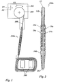
- a wire guide element 100a ( Fig. 1, Fig. 2 ) is arranged in a manner not shown in the drawing on a frame 200, which is part of a wire winding machine.
- a winch 300 is rotatably mounted, on which a wire 400 is wound.
- the wire 400 is passed through a passage 12 provided in an outer body 10a of the wire guide member 100a.
- teeth 500 for example, a stator of an electric machine. Characteristic of a distributed winding is that not a single tooth 500 is wrapped, but the wire leaves a groove between two teeth 500.
- the frame 200 is moved back and forth, wherein the arrows P1 and P2 in Fig. 1 show the movement possibilities.
- the wire 400 occurs as in Fig. 1 shown straight from the wire guide element 100a.
- the wire guide element is designed to be variable in shape, so that it is bent itself when acted upon with a certain Drahtzugkraft and thus reduces bending of the wire.
- the outer body 10a of the wire guide member 100a has a plurality of rigid sleeves 14a which are substantially in the form of a tube having two rings at both pipe ends.
- a further sleeve 14b is provided on the side of the frame 200 and comprises a somewhat longer shaft, and an outlet sleeve 14c serves to guide the wire securely out of the wire guide element 10a in the region of the wire outlet.
- the sleeves 14a are connected or coupled together by means of flexible connecting pieces 16a.
- the sleeve 14b is coupled via such a flexible connecting piece 16a with the next rigid sleeve 14a and in the region of the outlet sleeve 14c, a flexible further piece 16b is provided with a suitable fit.
- the arrangement, as in Fig. 2 is shown mimicking the vertebral column of a vertebrate, with the sleeves 14a corresponding to the vertebrae and the flexible connectors 16a to the discs.
- the rigid sleeves 14a contribute to the basic stability, but the flexible connectors 16a allow relative movement of the rigid sleeves 14a relative to one another such that the outer body 10a is flexible in itself.
- the adjusting elements according to the invention can be formed in this embodiment as flexible connecting pieces 16a and / or as sleeves 14a. These adjusting elements may be formed, for example, as a piezoelectric element, dielectric actuators, bimetal or shape memory material.
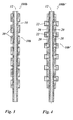
- a wire element 100b in a second embodiment of a wire element 100b, as shown in FIG Fig. 3 is shown in a flexible tube 18, the passage 12 is formed for the wire 400, and the outer body 10 b is formed by the flexible tube 18 and seated thereon outer metal sleeves 20, which are in particular annular and spaced apart so far that they on the one hand stabilize the flexible tube 18, but on the other hand allow a bending of the outer body 10b at least at the locations between the first metal sleeves.
- the adjusting elements according to the invention can be formed in this embodiment as a flexible hose 18 and / or as metal sleeves 20. These adjusting elements can be designed, for example, as a piezo element, dielectric actuators, bimetal or shape memory material, wherein the adjusting elements can also be arranged in the flexible tube 18.
- the outer body 10b' comprises, in addition to the flexible tube 18 and the first metal sleeves 20, second metal sleeves 22 whose inner diameter is more or less equal to the outer diameter of the first metal sleeves 20 and which rest exactly where Gaps are provided between the first part sleeves 20.
- This arrangement is particularly stable, yet retains nearly the same flexibility of the outer body 10b 'as the outer body 10b.
- the adjusting elements according to the invention can be formed in this embodiment as first metal sleeves 20 and / or as second metal sleeves 22. These adjusting elements may be formed, for example, as a piezoelectric element, dielectric actuators, bimetal or shape memory material.
- the outer body 10c comprises a tube made of a shape memory material, in particular a shape memory alloy such as Nitinol. Characteristics of a shape memory alloy is that it occupies a previously impressed shape at a certain temperature, for example after heating the material. The change in shape is based on a comparison of FIGS. 5 and 6 seen. Via electrical connections 24, by means of which the outer body 10c is directly energized, a current can be passed through the outer body 10c, the same for heating and thus taking the embossed shape Fig. 6 leads.
- the body 10c may be formed as a plurality of actuators.
- the outer body 10d comprises a plurality of adjusting elements or flat wires 26 formed as adjusting elements embedded in a flexible material 30 such as rubber.
- the Fig. 7 shows ten such flat wires, but conceivable arrangements with more (eleven, twelve, fourteen, fifteen, eighteen, twenty, etc.) or less (eight, six, three or two) flat wires conceivable.
- each actuator or each flat wire 26 is formed as an actuator, which consists for example of a shape memory alloy such as nitinol, provided with a plurality of heating coils 28 which can be controlled individually and so can cause a locally different heating of the flat wires 26 and cause a total change in shape of the outer body 10d of the wire guide member 100d.
- a shape memory alloy such as nitinol
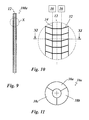
- the outer body 10 e includes a plurality of actuators 32, which change their volume under the action of a control variable such as an electrical voltage or a magnetic field.
- these actuators 32 are piezoelectric elements. In another embodiment, they are designed as dielectric actuators.
- the individual control elements 32 may be selectively acted upon under control by means 36 for controlling the control variable.
- a corresponding control voltage for effecting a change in volume of the respective piezoelectric element 32 is provided.
- actuating elements 32 or parts thereof are provided in individual sectors 38a, 38b, 38c, which can be selectively controlled. For example, if the sequence of actuators 32 in the sector 38a is driven, the volume of the actuators 32 may increase and cause the outer body 10e to flex toward the sectors 38b, 38c.
- the outer body 10 In one based on the Figures 12 and 13 illustrated sixth embodiment of the wire guide element 100 f, the outer body 10, a plurality of individual elements 40 which are movably disposed on support members 42. Through the individual elements 40 cables 44 are guided, which are wound on winches 46. The winches 46 are driven under control of an electric machine 48 to attract the cables 44. If one of the cables 44 is tightened in the outer body 10f and the other is not, bending of the outer body 10f will occur. The cables are attached to end pieces 50. In the area of the wire outlet 52, an in Fig. 13 shown sensor device 54 may be provided (as it is in Fig. 13 is shown).
- the sensor device 44 is provided, for example, as a piezoceramic sensor layer, which determines the extent of the force exerted by the wire 400 on the piezoceramic sensor layer. If the piezoceramic sensor layer 54 is subdivided into a plurality of ring sectors, the direction of the wire tensile force exerted by the wire 400 can also be determined. For example, two such sectors are each connected via lines 56 to a control device 58, which controls the electric machines 48, which move the winches 46, via control lines 60. The control device controls the wire tension and possibly their direction to a predetermined value.
- the adjusting elements according to the invention can be designed as supporting elements 42 and / or as individual elements 40 in this exemplary embodiment. These adjusting elements may be formed, for example, as a piezoelectric element, dielectric actuators, bimetal or shape memory material.
Landscapes
- Engineering & Computer Science (AREA)
- Chemical & Material Sciences (AREA)
- Power Engineering (AREA)
- Combustion & Propulsion (AREA)
- Mechanical Engineering (AREA)
- Manufacturing & Machinery (AREA)
- General Engineering & Computer Science (AREA)
- Physics & Mathematics (AREA)
- Plasma & Fusion (AREA)
- Manufacturing Cores, Coils, And Magnets (AREA)
- Resistance Heating (AREA)
- Manufacture Of Motors, Generators (AREA)
- Media Introduction/Drainage Providing Device (AREA)
Abstract
Description
- Die Erfindung betrifft ein Drahtführelement, insbesondere zum Führen eines zu wickelnden Drahtes in einer Drahtwickelmaschine oder zum Zuführen eines Lötdrahtes in einem Lötgerät oder eines Schweißzusatzes in Form eines Drahtes in einer Schweißmaschine. Die Erfindung betrifft auch eine Drahtwickelmaschine mit dem erfindungsgemäßen Drahtführelement. Sie betrifft auch ein Verfahren zum Einbringen von Draht zur Bildung einer Spule an oder in einem oder mehreren Bauteilen einer elektrischen Maschine, wobei der Draht durch ein erfindungsgemäßes Drahtführelement geführt wird. Die Erfindung betrifft ferner ein Verfahren zum Zuführen von Draht von einer Vorratseinrichtung zu einem Arbeitsbereich, wobei der Draht durch ein Drahtführelement geführt wird.
- Drahtführelemente weisen üblicherweise einen äußeren Körper auf, in welchem ein Durchlass für den Draht ausgebildet ist. Solche Drahtführelemente werden beispielsweise beim sogenannten Nadelwickelverfahren eingesetzt. Es handelt sich hierbei um ein Hub-Schwenk-Wickelverfahren zum Einbringen von Draht zur Bildung einer Spule an oder in einem oder mehreren Bauteilen einer elektrischen Maschine (an einem Stator, Rotor oder einem Transformator). Um hierbei den zu wickelnden Draht definiert auf dem einen oder mehreren Bauteilen (den sogenannten Wickelkörpern) abzulegen, muss das Drahtführelement bewegt werden, nämlich so geführt werden, dass der aus ihm herausgeführte (insbesondere herausgezogene) Draht die Zwischenräume passieren kann. Hierbei soll der herausgeführte Draht den bereits abgelegten Draht nicht berühren; denn dieser soll nicht beschädigt werden. Ein Hub-Schwenk-Wickelverfahren, insbesondere das Nadelwickelverfahren, wird insbesondere auch zur Herstellung von sogenannten verteilten Wicklungen eingesetzt, bei dem das Drahtführelement durch Nuten eines Statorblechpakets geführt wird. Es wird hierbei nicht ein einzelner Zahn des Statorblechpakets vollständig umwickelt, sondern in einer Folge von mindestens drei Nuten zwischen Zähnen wird die Wicklung von der ersten Nut in die dritte Nut und wieder zurück in die erste Nut geführt, so dass die zweite Nut frei bleibt.
- Beim Austreten des zu führenden Drahts aus dem Drahtführelement kann selbiger besonders stark an dessen Drahtauslass abgebogen werden, so dass es zu einer Beschädigung seiner Isolierung kommen kann. Um dem vorzubeugen, wird häufig eine sehr dicke Isolierung vorgesehen, insbesondere z.B. mit dem höchsten Grad gemäß IEC 60317.
- Insgesamt werden bei den bekannten Hub-Schwenk- Wickelverfahren nur geringe sogenannte Füllfaktoren erzielt, d.h. es bleiben viele Freiräume dort, wo an sich die Wicklung platziert sein sollte, wobei diese Freiräume später weitgehend mit Harz gefüllt werden.
- Zur Erhöhung der Dichte beim Wickeln und Verringerung der Belastung des Drahtes am Drahtauslass, bei welchem der Draht um einen Winkel von z.B. 90° gebogen wird, sieht die
DE 10 2011 008 662 A1 folgendes Nadelwickelsystem vor: Ein starres Drahtführelement wird so bewegt, dass seine Drahtaustrittsdrüse stets ins Zentrum eines virtuellen Kreises gerichtet ist und so einen virtuellen Schwerpunkt definiert. Dieses Nadelwickelsystem hat den Nachteil, dass eine aufwendige Mechanik vorgesehen ist, welche sehr viel Platz einnimmt, so dass sie insbesondere zur Wicklung sehr kleiner Wicklungen in kleinen Nuten schlecht geeignet ist. Außerdem ist die Mechanik störanfällig. - Es ist die Aufgabe der vorliegenden Erfindung, einen weniger aufwendigen Weg aufzuzeigen, wie Draht an einem Drahtauslass eines Drahtführelements geringer belastet werden kann.
- Die Aufgabe wird durch ein Drahtführelement mit den Merkmalen gemäß Patentanspruch 1, durch ein Verfahren mit den Merkmalen gemäß Patentanspruch 12 und durch ein Verfahren mit den Merkmalen gemäß Patentanspruch 15 gelöst.
- Das erfindungsgemäße Drahtführelement, insbesondere zum Führen eines zu wickelnden Drahtes in einer Drahtwickelmaschine oder zum Zuführen eines Lötdrahtes in einem Lötgerät oder eines Schweißzusatzes in Form eines Drahtes in einer Schweißmaschine, weist somit einen äußeren Körper auf, in welchem ein Durchlass für einen Draht ausgebildet ist, wobei der äußere Körper zumindest abschnittsweise derart formveränderlich ist, dass sich hierbei auch die Form des Durchlasses ändert. Das Drahtführelement weist einen äußere Körper mit einer Vielzahl von Stellelementen auf, welche unter der Wirkung einer elektrischen Spannung, eines elektrischen Stromes oder eines Magnetfeldes als physikalischer Stellgröße ihre Form verändern, insbesondere ihr Volumen ändern. Der Körper weist Mittel auf, die einzelnen Stellelemente selektiv mit der physikalischen Stellgröße elektrischer Spannung, elektrischem Strom oder Magnetfeld zu beaufschlagen. Solche Stellelemente wie z.B. Piezoelemente oder dielektrische Aktoren sind präzise ansteuerbar, um eine Formveränderung des äußeren Körpers definiert einzustellen.
- Eine Vielzahl von Stellelementen sind als zwei oder mehr Stellelemente zu verstehen.
- Auf diese Weise kann dafür gesorgt werden, dass sich das Drahtführelement bei starker Belastung des Drahtes am Auslass des Drahtführelements derart in seiner Form verändert, dass sich diese Belastung verringert.
- Insbesondere beim Einsatz in einer Drahtwickelmaschine können hohe Werte für einen Füllfaktor erzielt werden, d.h. der zu wickelnde Draht kann sehr dicht gewickelt werden. Der Draht kann hierbei auch eine dünnere Isolierung als bei bisherigen gleichartigen Wicklungen aufweisen.
- Es gibt mehrere Ausführungsformen von aktiven Drahtführelementen. Als aktiv ist ein solches Drahtführelement anzusehen, bei dem eine Änderung einer äußeren Bedingung (physikalische Größe wie z.B. Temperatur) oder eines Steuerparameters (Beaufschlagung mit einer elektrischen oder magnetischen Größe) die Formveränderung des äußeren Körpers bewirkt.
- Es kann vorgesehen sein, dass das Drahtführelement passiv ausgeführt ist, d.h. (unmittelbar) unter der Wirkung einer durch einen Draht in den Durchlass auf ihn ausgeübten Kraft seine Form verändern. Eine passive Ausführungsform hat den Vorteil, dass keine aufwendige Steuerung notwendig ist und daher komplexe und fehleranfällige Bauelemente entfallen.
- Es kann vorgesehen sein, dass am Drahtführelement eine Vielzahl von Stellelementen längs der Längserstreckung des äußeren Körpers angeordnet. Bevorzugt sind ferner zumindest zwei und besonders bevorzugt zumindest drei Stellelemente in unterschiedlichen Sektoren eines Ringes um den Durchlass angeordnet.
- Es kann vorgesehen sein, dass bei dem Drahtführelement der äußere Körper eine Mehrzahl von starren Hülsen aufweist, welche paarweise durch jeweils zumindest ein flexibles Verbindungsstück miteinander gekoppelt sind. Während die starren Hülsen für eine Grundstabilität sorgen, erlauben die flexiblen Verbindungsstücke die Formveränderung.
- Es kann vorgesehen sein, dass der äußere Körper einen flexiblen Schlauch und erste Metallhülsen aufweisen, welche auf dem Schlauch aufsitzen und voneinander beabstandet sind. Statt Metallhülsen können auch andere starre Hülsen, etwa aus Hartplastik, vorgesehen sein. Der flexible Schlauch selbst sorgt somit für die mögliche Formveränderung, allerdings lediglich dort, wo nicht die ersten Metallhülsen auf ihm aufsitzen, sondern in dem Zwischenbereich zwischen zwei benachbarten ersten Metallhülsen. Die ersten Metallhülsen sorgen für die notwendige Stabilität, die der flexible Schlauch als solche alleine nicht in dem gewünschten Maße bietet.
- Es kann vorgesehen sein, dass zu den ersten Metallhülsen, welche dann ringförmig ausgebildet sind und einen ersten Innendurchmesser aufweisen, dass ringförmige zweite Metallhülsen auf einem Abschnitt je zweier zueinander benachbarter erster Metallhülsen aufsitzen, wobei diese ringförmigen zweiten Metallhülsen einen zweiten Innendurchmesser aufweisen, welcher größer als der erste Innendurchmesser ist. Sie umgeben somit den flexiblen Schlauch dort, wo keine erste Metallhülse vorhanden ist und schützen diesen flexiblen Schlauch somit, ohne aber dessen Flexibilität wesentlich einzuschränken.
- Es kann vorgesehen sein, dass bei dem Drahtführelementes der äußere Körper rohrförmig ausgebildet ist und zumindest einen Teil aus einem Material umfasst, welches bei einer Temperaturänderung eine Formänderung dieses zumindest einen Teils bewirkt.
- Ein solches Material ist insbesondere ein Formgedächtnismaterial, typischerweise eine Formgedächtnislegierung (z.B. Nitinol). Der äußere Körper umfasst insbesondere ein Rohr aus einem solchen Formgedächtnismaterial, und an selbigem sind elektrische Anschlüsse zum Bestromen des Formgedächtnismaterials bereitgestellt, wobei durch das Beschicken des Formgedächtnismaterials selbst mit dem elektrischen Strom sich dieses erwärmt, und somit die gewünschte Temperaturänderung zur Formänderung des äußeren Körpers bewirkt wird.
- Alternativ kann aus einer Formgedächtnislegierung (oder alternativ einem Bimetall) eine Mehrzahl von Flachdrähten ausgebildet sein. Auf diesen Flachdrähten soll jeweils eine Mehrzahl von Heizspulen angeordnet sein. Die Flachdrähte sollen zusammen mit den Heizspulen in ein elastisches, elektrisch isolierendes Material eingebettet sein, welches insbesondere thermisch leitfähig ist. Durch Beaufschlagung der Heizspulen mit einem Heizstrom erwärmen sich diese und damit die Flachdrähte, wobei bei einer Formgedächtnislegierung oder einem Bimetall der Flachdraht sodann seine Form ändert und somit auch die Form des äußeren Körpers ändert.
- In einer Ausgestaltung kann vorgesehen sein, dass der äußere Körper mit einem oder mehreren Einzelelementen, in welchem zumindest ein Seilzug zur Formveränderung des Drahtführelementes geführt ist. Das Drahtführelement weist zu jedem Seilzug eine Winde oder Zugeinrichtung außerhalb des äußeren Körpers mit einem zugehörigen elektrischen Antrieb auf, mittels dessen der jeweilige Seilzug, insbesondere selektiv, zur Formveränderung einsetzbar ist. Bei dieser (elektro-) mechanischen Ausführungsform des Drahtführelementes besteht eine geringere Fehleranfälligkeit gegenüber Störungen in elektrischen Einrichtungen. Das Einzelelement und die mehreren Einzelelemente können vorzugsweise in Verbindung mit, d.h. zusätzlich zu den Stellelementen ausgebildet sein.
- Bei allen Drahtführelementen ist bevorzugt eine Sensoreinrichtung zur Ermittlung der von dem Draht auf das Drahtführelement ausgeübten Kraft angeordnet, insbesondere im Bereich eines Drahtauslasses. Mittels dieser Sensoreinrichtung, die insbesondere eine piezokeramische Sensorschicht aufweisen kann, können solche Messwerte ermittelt werden, die im Rahmen einer Steuerung oder Regelung eingesetzt werden, bei der entweder die Formveränderung durch die Stellgröße bewirkt wird (bei aktiven Drahtelementen), oder bei der eine zusätzliche Drahtbremse außerhalb des Drahtführelements die Drahtzugkraft einstellt.
- Zur Erfindung gehört auch eine Drahtwickelmaschine mit dem erfindungsgemäßen Drahtführelement.
- Bei dem erfindungsgemäßen Verfahren zum Einbringen von Draht zur Bildung einer Spule an oder in einem oder mehreren Bauteilen einer elektrischen Maschine wird der Draht durch ein Drahtführelement der erfindungsgemäßen Art geführt. Das Drahtführelement ändert entweder unter der Wirkung einer von dem Draht ausgeübten Kraft (bei passivem Drahtführelement) oder aufgrund einer aktiven Ansteuerung einer mechanischen oder elektrischen Stellgröße (bei aktivem Drahtführelement) die Form seines äußeren Körpers, insbesondere auch wiederholt. Das Drahtführelement weist einen äußere Körper mit einer Vielzahl von Stellelementen auf, welche unter der Wirkung einer elektrischen Spannung, eines elektrischen Stromes oder eines Magnetfeldes als physikalischer Stellgröße ihre Form verändern, insbesondere ihr Volumen ändern. Der Körper weist Mittel auf, die einzelnen Stellelemente selektiv mit der physikalischen Stellgröße elektrischer Spannung, elektrischem Strom oder Magnetfeld zu beaufschlagen. Solche Stellelemente wie z.B. Piezoelemente oder dielektrische Aktoren sind präzise ansteuerbar, um eine Formveränderung des äußeren Körpers definiert einzustellen.
- Dieses Verfahren ist vor allem auch dann vorteilhaft einsetzbar, wenn es ohne die Formänderung des äußeren Körpers zu einer Belastung des Drahts und insbesondere seiner Isolierung kommen könnte.
- Dieser Vorteil ist insbesondere dann gegeben, wenn die Spule als verteilte Wicklung bereitgestellt werden soll, aber auch z.B. beim Wickeln von Einzelzahnspulen oder konzentrierten Wicklungen.
- Im Falle der vorgesehenen Sensoreinrichtung gibt selbige Messsignale ab, und in Antwort auf diese erfolgt die Ansteuerung der mechanischen oder elektrischen Stellgröße.
- Das erfindungsgemäße Verfahren zum Zuführen von Draht von einer Vorratseinrichtung zu einem Arbeitsbereich beinhaltet, dass der Draht durch ein Drahtführelement geführt wird, wobei die von dem Draht auf das Drahtführelement ausgeübte Drahtzugkraft gemessen wird und in Abhängigkeit von dieser die Form von zumindest einem Teil des Drahtführelements derart geändert wird, dass die Drahtzugkraft verringert und/oder auf einen vorbestimmten Wert geregelt wird.
- Die Drahtzugkraft kann insbesondere im Hinblick auf ihren Betrag und ihre Richtung, vorzugsweise in mehrere Richtungen, gemessen werden, und ein oder mehrere Sollwerte bei einer Regelung kann bzw. können sich auf den Betrag und/oder die Richtung beziehen.
- Nachfolgend werden bevorzugte Ausführungsformen der Erfindung unter Bezug auf die Zeichnung näher beschrieben, in der:
- Fig. 1
- schematisch eine Drahtwickelmaschine mit einem Drahtführelement gemäß einer ersten Ausführungsform beim Vorsehen einer verteilten Wicklung veranschaulicht,
- Fig. 2
- das Drahtführelement gemäß der ersten Ausführungsform aus
Fig. 1 in vergrößerter Ansicht im Schnitt veranschaulicht, - Fig. 3
- eine zweite Ausführungsform des Drahtführelements im Schnitt veranschaulicht,
- Fig. 4
- eine Abwandlung der zweiten Ausführungsform des Drahtführelements im Schnitt veranschaulicht,
- Fig. 5
- eine dritte Ausführungsform des Drahtführelements im Schnitt in einem Grundzustand veranschaulicht,
- Fig. 6
- das Drahtführelement aus
Fig. 5 in einem verformten Zustand veranschaulicht, - Fig. 7
- eine vierte Ausführungsform des Drahtführelements im Schnitt veranschaulicht und
- Fig. 8
- schematisch die Besetzung eines bei dem Drahtführelement aus
Fig. 7 verwendeten Flachdrahtes mit Heizspulen veranschaulicht, - Fig. 9
- eine fünfte Ausführungsform des erfindungsgemäßen Drahtführelementes im Schnitt veranschaulicht,
- Fig. 10
- den Ausschnitt X aus
Fig. 9 in vergrößerter Darstellung zeigt, - Fig. 11
- den Schnitt XI-XI aus
Fig. 10 zeigt, - Fig. 12
- eine sechste Ausführungsform des Drahtführelementes im Schnitt veranschaulicht und
- Fig. 13
- die Einbindung des Drahtführelements aus
Fig. 12 in einen Regelkreis veranschaulicht. - Ein Drahtführelement 100a (
Fig. 1, Fig. 2 ) ist auf eine in der Zeichnung nicht gezeigte Weise an einem Gestell 200 angeordnet, welches Teil einer Drahtwickelmaschine ist. An dem Gestell 200 ist drehbar eine Winde 300 gelagert, auf der ein Draht 400 aufgewickelt ist. Der Draht 400 ist durch einen in einem äußeren Körper 10a des Drahtführelements 100a vorgesehenen Durchlass 12 geführt. In derFig. 1 ist dargestellt, wie der Draht zur Bildung einer verteilten Wicklung um hier nur symbolisch gezeigte Zähne 500 beispielsweise eines Stators einer elektrischen Maschine gewickelt wird. Kennzeichen einer verteilten Wicklung ist, dass nicht ein einzelner Zahn 500 umwickelt wird, sondern der Draht eine Nut zwischen zwei Zähnen 500 auslässt. - Damit der Draht an die jeweils richtige Stelle geführt ist, wird das Gestell 200 hin- und herbewegt, wobei die Pfeile P1 und P2 in
Fig. 1 die Bewegungsmöglichkeiten anzeigen. Nicht immer tritt der Draht 400 wie inFig. 1 gezeigt gerade aus dem Drahtführelement 100a aus. Um zu vermeiden, dass sich der Draht in zu starkem Maße biegt, ist vorliegend das Drahtführelement formveränderlich ausgebildet, so dass es bei Beaufschlagung mit einer bestimmten Drahtzugkraft selbst gebogen wird und so eine Biegung des Drahtes verringert. - Wie in
Fig. 2 zu sehen, weist der äußere Körper 10a des Drahtführelements 100a eine Mehrzahl von starren Hülsen 14a auf, die im Wesentlichen die Form eines Rohrs mit zwei Ringen an beiden Rohrenden haben. Eine weitere Hülse 14b ist auf der Seite des Gestells 200 vorgesehen und umfasst einen etwas längeren Schaft, und eine Auslasshülse 14c dient dazu, den Draht sicher im Bereich des Drahtauslasses aus dem Drahtführelement 10a zu führen. Die Hülsen 14a sind mittels flexibler Verbindungsstücke 16a miteinander verbunden bzw. gekoppelt. Die Hülse 14b ist über ein solches flexibles Verbindungsstück 16a mit der nächsten starren Hülse 14a gekoppelt und im Bereich der Auslasshülse 14c ist ein flexibles weiteres Stück 16b mit geeigneter Passform vorgesehen. Die Anordnung, wie sie inFig. 2 gezeigt ist, ahmt die Wirbelsäule eines Wirbeltieres nach, wobei die Hülsen 14a den Wirbeln und die flexiblen Verbindungsstücke 16a den Bandscheiben entsprechen. Wie bei einer Wirbelsäule tragen die starren Hülsen 14a zur Grundstabilität bei, die flexiblen Verbindungsstücke 16a ermöglichen aber eine Relativbewegung der starren Hülsen 14a zueinander, so dass der äußere Körper 10a in sich biegbar ist. Die erfindungsgemäßen Stellelemente können in diesen Ausführungsbeispiel als flexible Verbindungsstücke 16a und/oder als Hülsen 14a ausgebildet sein. Diese Stellelemente können zum Beispiel als Piezoelement, dielektrische Aktoren, Bimetall oder Formgedächtnismaterial ausgebildet sein. - Bei einer zweiten Ausführungsform eines Drahtelements 100b, wie es in
Fig. 3 gezeigt ist, ist in einem flexiblen Schlauch 18 der Durchlass 12 für den Draht 400 ausgebildet, und der äußere Körper 10b ist durch den flexiblen Schlauch 18 und darauf aufsitzende äußere Metallhülsen 20 gebildet, welche insbesondere ringförmig sind und soweit zueinander beabstandet sind, dass sie einerseits den flexiblen Schlauch 18 stabilisieren, andererseits aber ein Sich-Biegen des äußeren Körpers 10b zumindest an den Stellen zwischen den ersten Metallhülsen erlauben. Die erfindungsgemäßen Stellelemente können in diesen Ausführungsbeispiel als flexibler Schlauch 18 und/oder als Metallhülsen 20 ausgebildet sein. Diese Stellelemente können zum Beispiel als Piezoelement, dielektrische Aktoren, Bimetall oder Formgedächtnismaterial ausgebildet sein wobei die Stellelemente auch in dem flexiblen Schlauch 18 angeordnet sein können. - In einer in
Fig. 4 gezeigten Abwandlung dieser zweiten Ausführungsform des Drahtführelements 100b' umfasst der äußere Körper 10b' zusätzlich zu dem flexiblen Schlauch 18 und den ersten Metallhülsen 20 zweite Metallhülsen 22, deren Innendurchmesser mehr oder weniger dem Außendurchmesser der ersten Metallhülsen 20 entspricht, und die genau dort aufsitzen, wo Zwischenräume zwischen den ersten Teilhülsen 20 vorgesehen sind. Diese Anordnung ist besonders stabil, bewahrt aber dennoch nahezu dieselbe Flexibilität des äußeren Körpers 10b', wie sie der äußere Körper 10b hat. Die erfindungsgemäßen Stellelemente können in diesen Ausführungsbeispiel als erste Metallhülsen 20 und/oder als zweite Metallhülsen 22 ausgebildet sein. Diese Stellelemente können zum Beispiel als Piezoelement, dielektrische Aktoren, Bimetall oder Formgedächtnismaterial ausgebildet sein. - Bei einer dritten Ausführungsform eines Drahtführelements 100c gemäß
Fig. 5 und 6 umfasst der äußere Körper 10c ein Rohr aus einem Material mit Formgedächtnis, insbesondere einer Formgedächtnislegierung wie z.B. Nitinol. Kennzeichen einer Formgedächtnislegierung ist es, dass diese bei einer bestimmten Temperatur, z.B. nach einem Erwärmen des Materials, eine zuvor eingeprägte Form einnimmt. Die Formänderung ist anhand eines Vergleichs derFiguren 5 und 6 ersichtlich. Über elektrische Anschlüsse 24, mittels derer der äußere Körper 10c unmittelbar bestrombar ist, lässt sich ein Strom durch den äußeren Körper 10c leiten, der zur Erwärmung desselben und damit Einnahme der eingeprägten Form gemäßFig. 6 führt. Der Körper 10c kann als eine Vielzahl von Stellelementen ausgebildet sein. - Bei einer vierten Ausführungsform des Drahtführelements 100d gemäß
Fig. 7 und 8 umfasst der äußere Körper 10d eine Mehrzahl von Stellelemente oder Flachdrähten 26 die als Stellelemente ausgebildet sind, welche in ein flexibles Material 30 wie beispielsweise Gummi eingebettet sind. DieFig. 7 zeigt zehn solcher Flachdrähte, denkbar sind aber auch Anordnungen mit mehr (elf, zwölf, vierzehn, fünfzehn, achtzehn, zwanzig, etc.) oder weniger (acht, sechs, drei oder zwei) Flachdrähten denkbar. - Wie in
Fig. 8 zu sehen, ist jedes Stellelement bzw. jeder Flachdraht 26 ausgebildet als Stellelement, der beispielsweise aus einer Formgedächtnislegierung wie etwa Nitinol besteht, mit einer Mehrzahl von Heizspulen 28 versehen, die einzeln angesteuert werden können und so eine lokal verschiedene Erwärmung der Flachdrähte 26 bewirken können und insgesamt eine Formänderung des äußeren Körpers 10d des Drahtführelements 100d bewirken. - Bei einer fünften Ausführungsform des Drahtführelements 100e, wie sie anhand der
Figuren 9 bis 11 veranschaulicht ist, umfasst der äußere Körper 10e eine Mehrzahl von Stellelementen 32, welche unter Beaufschlagung mit einer Steuergröße wie beispielsweise einer elektrischen Spannung oder eines Magnetfeldes ihr Volumen ändern. In einer Ausführungsform sind diese Stellelemente 32 piezoelektrische Elemente. In einer anderen Ausführungsform sind sie als dielektrische Aktoren ausgebildet. Über inFig. 10 symbolisch gezeigte Zuführleitungen 34 können die einzelnen Stellelemente 32 selektiv unter Steuerung durch Mittel 36 zum Steuern mit der Steuergröße beaufschlagbar sein. Im Beispielsfalle eines Piezoelements als Stellelement 32 wird eine entsprechende Steuerspannung zur Bewirkung einer Volumenänderung des jeweiligen Piezoelements 32 bereitgestellt. - Damit der äußere Körper 10e des Drahtführelements 100e nicht nur seine Länge verändert, sondern sich auch biegt, sind in einzelnen Sektoren 38a, 38b, 38c jeweils unterschiedliche Stellelemente 32 bzw. Teile von solchen vorgesehen, die selektiv angesteuert werden können. Wird beispielsweise die Folge von Stellelementen 32 im Sektor 38a angesteuert, kann sich das Volumen der Stellelemente 32 vergrößern und ein Sich-Biegen des äußeren Körpers 10e zu den Sektoren 38b, 38c hin bewirken.
- Die in
Fig. 11 gezeigte Zahl von drei Sektoren ist lediglich beispielhaft, es können auch zwei oder mehr als drei Sektoren vorgesehen sein. - Bei einer anhand der
Figuren 12 und13 veranschaulichten sechsten Ausführungsform des Drahtführelements 100f umfasst der äußere Körper 10feine Mehrzahl von Einzelelementen 40, welche beweglich auf Stützelementen 42 angeordnet sind. Durch die Einzelelemente 40 sind Seilzüge 44 geführt, welche auf Winden 46 aufgewickelt sind. Die Winden 46 sind unter Ansteuerung einer elektrischen Maschine 48 antreibbar, um die Seilzüge 44 anzuziehen. Wird in dem äußeren Körper 10f einer der Seilzüge 44 angezogen und der andere nicht, kommt es zu einem Sich-Biegen des äußeren Körpers 10f. Die Seilzüge sind an Endstücken 50 befestigt. Im Bereich des Drahtauslasses 52 kann eine inFig. 13 gezeigte Sensoreinrichtung 54 vorgesehen sein (so wie es inFig. 13 gezeigt ist). Die Sensoreinrichtung 44 ist beispielsweise als piezokeramische Sensorschicht bereitgestellt, welche das Ausmaß der von dem Draht 400 auf die piezokeramische Sensorschicht ausgeübten Kraft ermittelt. Ist die piezokeramische Sensorschicht 54 in mehrere Ringsektoren unterteilt, lässt sich auch die Richtung der von dem Draht 400 ausgeübten Drahtzugkraft ermitteln. Beispielsweise sind zwei solche Sektoren jeweils über Leitungen 56 mit einer Regeleinrichtung 58 verbunden, die über Steuerleitungen 60 die elektrischen Maschinen 48 ansteuert, welche die Winden 46 bewegen. Die Regeleinrichtung regelt die Drahtzugkraft und ggf. deren Richtung auf einen vorbestimmten Wert. Die erfindungsgemäßen Stellelemente können in diesen Ausführungsbeispiel als Stützelemente 42 und/oder als Einzelelemente 40 ausgebildet sein. Diese Stellelemente können zum Beispiel als Piezoelement, dielektrische Aktoren, Bimetall oder Formgedächtnismaterial ausgebildet sein.
Claims (15)
- Drahtführelement (100a, 100b, 100b', 100c, 100d, 100e, 100f), insbesondere zum Führen eines zu wickelnden Drahtes (400) in einer Drahtwickelmaschine (200, 300) oder zum Zuführen eines Lötdrahtes in einem Lötgerät oder eines Schweißzusatzes in Form eines Drahtes in einer Schweißmaschine, mit einem äußeren Körper (10a, 10b, 10b', 10c, 10d, 10e, 10f) in dem ein Durchlass (12) für einen Draht ausgebildet ist, wobei der äußere Körper (10a, 10b, 10b', 10c, 10d, 10e, 10f) zumindest abschnittsweise derart formveränderlich ist, dass sich hierbei auch die Form des Durchlasses (12) ändert.
dadurch gekennzeichnet,
dass der äußere Körper eine Vielzahl von Stellelementen (32) aufweist, die unter der Wirkung einer elektrischen Spannung, eines elektrischen Stromes oder eines Magnetfeldes als physikalischer Stellgröße ihre Form verändern, insbesondere ihr Volumen ändern, und wobei der Körper Mittel (34, 36) aufweist, die einzelnen Stellelemente (32) selektiv mit der physikalischen Stellgröße elektrischer Spannung, elektrischem Strom oder Magnetfeld zu beaufschlagen. - Drahtführelement nach Anspruch 1,
dadurch gekennzeichnet,
dass eine Vielzahl von Stellelementen (32) längs der Längserstreckung des äußeren Körpers (10e) angeordnet sind. - Drahtführelement nach einem der vorangehenden Ansprüche,
dadurch gekennzeichnet,
dass bei dem Drahtführelement zumindest zwei und bevorzugt zumindest drei Stellelemente (32) in unterschiedlichen Sektoren (38a, 38b, 38c) eines Rings um den Durchlass (12) angeordnet sind. - Drahtführelement nach einem der vorangehenden Ansprüche,
dadurch gekennzeichnet,
dass bei dem Drahtführelement der äußere Körper (10a) eine Mehrzahl von starren Hülsen (14a, 14b) aufweist, die paarweise durch jeweils zumindest ein flexibles Verbindungsstück (16a) miteinander gekoppelt sind, vorzugsweise, dass bei dem Drahtführelement der äußere Körper (10b, 10b') einen flexiblen Schlauch (18) und erste Metallhülsen (20) aufweist, die auf dem Schlauch (18) aufsitzen und voneinander beabstandet sind. - Drahtführelement nach einem der vorangehenden Ansprüche,
dadurch gekennzeichnet,
dass bei dem Drahtführelement ringförmige erste Metallhülsen (20) mit erstem Innendurchmesser den flexiblen Schlauch (18) unmittelbar umgeben und ringförmige zweite Metallhülsen (22) mit zweitem Innendurchmesser, der größer als der erste Innendruchmesser ist, auf einem Abschnitt je zweier zueinander benachbarter erster Metallhülsen (20) aufsitzen und so den flexiblen Schlauch (18) dort umgeben, wo keine erste Metallhülse (20) vorhanden ist. - Drahtführelement nach einem der vorangehenden Ansprüche,
dadurch gekennzeichnet,
dass bei dem Drahtführelement der äußere Körper (10c) rohrförmig ausgebildet ist und zumindest einen Teil aus einem Material umfasst, das bei einer Temperaturänderung eine Formänderung dieses zumindest einen Teils bewirkt, vorzugsweise,dass das Drahtführelement ein Rohr (10c) aus einem Formgedächtnismaterial aufweist, insbesondere einer Formgedächtnislegierung aufweist, wobei an dem Rohr (10c) elektrische Anschlüsse (24) zum Bestromen des Formgedächtnismaterials bereitgestellt sind. - Drahtführelement nach Anspruch 6,
dadurch gekennzeichnet,
dass das Drahtführelement eine Mehrzahl von Flachdrähten (26) aus einer Formgedächtnislegierung oder einem Bimetall aufweist, auf dem jeweils eine Mehrzahl von Heizspulen (28) angeordnet sind und die zusammen mit diesen Heizspulen (28) in ein elastisches, elektrisch isolierendes Material (30) eingebettet sind, welches insbesondere thermisch leitfähig ist. - Drahtführelement nach einem der vorangehenden Ansprüche,
dadurch gekennzeichnet,
dass bei dem Drahtführelement der äußere Körper (10f) zumindest ein Einzelelement (40) umfasst, wobei in jedem Einzelelement (40) zumindest ein Seilzug (44) zur Formveränderung des Drahtführelements (100f) geführt ist, wobei das Drahtführelement (100f) zu jedem Seilzug (44) eine Winde (46) außerhalb des äußeren Körpers mit einem zugehörigen elektrischen Antrieb (48) umfasst, mittels dessen der jeweilige Seilzug (44), insbesondere selektiv, zur Formveränderung einsetzbar ist. - Drahtführelement nach einem der vorangehenden Ansprüche,
dadurch gekennzeichnet,
dass das Drahtführelement im Bereich eines Drahtauslasses (52) eine Sensoreinrichtung (54) aufweist zur Ermittlung der von dem Draht auf das Drahtführelement (100c, 100d, 100e, 100f) ausgeübten Kraft. - Drahtführelement nach Anspruch 9,
dadurch gekennzeichnet,
dass bei dem Drahtführelement die Sensoreinrichtung (54) eine piezokeramische Sensorschicht aufweist. - Drahtwickelmaschine (200, 300) mit einem Drahtführelement (100a, 100b, 100b', 100c, 100d, 100e, 100f) nach einem der Ansprüche 1 bis 10.
- Verfahren zum Einbringen von Draht zur Bildung einer Spule an oder in einem oder mehreren Bauteilen einer elektrischen Maschine, wobei der Draht (400) durch ein Drahtführelement (100a, 100b, 100b', 100c, 100d, 100e, 100f) nach einem Ansprüche 1 bis 12 geführt wird und das Drahtführelement (100a, 100b, 100b', 100c, 100d, 100e, 100f) entweder unter der Wirkung einer von dem Draht (400) ausgeübten Kraft oder aufgrund einer aktiven Ansteuerung einer mechanischen oder elektrischen Stellgröße die Form seines äußeren Körpers (10a, 10b, 10b', 10c, 10d, 10e, 10f) ändert, insbesondere wiederholt ändert.
dadurch gekennzeichnet,
dass der äußere Körper des Drahtführelements eine Vielzahl von Stellelementen (32) aufweist, deren Form oder Volumen unter der Wirkung einer elektrischen Spannung, eines elektrischen Stromes oder eines Magnetfeldes als physikalische Stellgröße verändert wird und wobei der Körper Mittel (34, 36) aufweist, mittels derer die einzelnen Stellelemente (32) selektiv mit der physikalischen Stellgröße elektrische Spannung, elektrischer Strom oder Magnetfeld beaufschlagt werden. - Verfahren nach Anspruch 12,
dadurch gekennzeichnet,
dass bei dem Verfahren die Spule als verteilte Wicklung bereitgestellt wird. - Verfahren nach Anspruch 12 oder 13,
dadurch gekennzeichnet,
dass bei dem Verfahren ein Drahtführelement (100c, 100d, 100e, 100f) nach Anspruch 9 oder 10 eingesetzt wird, und wobei die Ansteuerung in Reaktion auf von der Sensoreinrichtung (54) abgegebene Messsignale erfolgt. - Verfahren zum Zuführen von Draht von einer Vorratseinrichtung zu einem Arbeitsbereich, wobei bei dem Verfahren der Draht durch ein Drahtführelement (100c, 100d, 100e, 100f) geführt wird, wobei die von dem Draht auf das Drahtführelement (100c, 100d, 100e, 100f) ausgeübte Drahtzugkraft gemessen wird und in Abhängigkeit von dieser die Form von zumindest einem Teil des Drahtführelements (100c, 100d, 100e, 100f) derart geändert wird, dass die Drahtzugkraft verringert und/oder auf einen vorbestimmten Wert geregelt wird.
dadurch gekennzeichnet,
dass die Drahtzugkraft im Hinblick auf ihren Betrag und ihre Richtung gemessen wird.
Applications Claiming Priority (1)
| Application Number | Priority Date | Filing Date | Title |
|---|---|---|---|
| DE102014108208.7A DE102014108208A1 (de) | 2014-06-11 | 2014-06-11 | Drahtführelement, Drahtwickelmaschine mit einem solchen, Verfahren zum Einbringen von Draht und Verfahren zum Zuführen von Draht |
Publications (3)
| Publication Number | Publication Date |
|---|---|
| EP2963663A2 true EP2963663A2 (de) | 2016-01-06 |
| EP2963663A3 EP2963663A3 (de) | 2016-01-20 |
| EP2963663B1 EP2963663B1 (de) | 2019-12-25 |
Family
ID=53502426
Family Applications (1)
| Application Number | Title | Priority Date | Filing Date |
|---|---|---|---|
| EP15171635.4A Active EP2963663B1 (de) | 2014-06-11 | 2015-06-11 | Drahtführelement, drahtwickelmaschine mit einem solchen, verfahren zum einbringen von draht und verfahren zum zuführen von draht |
Country Status (2)
| Country | Link |
|---|---|
| EP (1) | EP2963663B1 (de) |
| DE (1) | DE102014108208A1 (de) |
Cited By (5)
| Publication number | Priority date | Publication date | Assignee | Title |
|---|---|---|---|---|
| WO2018187909A1 (zh) * | 2017-04-10 | 2018-10-18 | 深圳市立昌机电设备有限公司 | 一种电机定子绕线机单轴主轴箱及其调节方法 |
| CN109216014A (zh) * | 2018-09-20 | 2019-01-15 | 东莞市威元电子科技有限公司 | 变压器绞线绕线一体装置 |
| CN109378952A (zh) * | 2018-10-18 | 2019-02-22 | 金华市捷欣智能科技有限公司 | 一种扁铜线绕线成型机 |
| CN109546821A (zh) * | 2018-12-25 | 2019-03-29 | 嘉兴藤飞精工科技有限公司 | 定子铁芯绕线机用长短绝缘套管推送装置 |
| CN111684692A (zh) * | 2018-01-30 | 2020-09-18 | 劳斯莱斯德国有限两合公司 | 用于电机的包括具有预制的插上元件和连接元件的线圈的有源部件、电机以及制造方法 |
Families Citing this family (4)
| Publication number | Priority date | Publication date | Assignee | Title |
|---|---|---|---|---|
| CN110088861B (zh) * | 2016-11-18 | 2022-05-13 | 弗劳恩霍夫应用研究促进协会 | 用于生产绕组元件的方法和装置 |
| DE102020114398A1 (de) | 2020-05-28 | 2021-12-02 | Audi Aktiengesellschaft | Nadelwickelvorrichtung zum Bewickeln eines elektromagnetisch wirksamen Bauteils einer elektrischen Maschine sowie Verfahren zum Betreiben einer Nadelwickelvorrichtung |
| DE102020119497A1 (de) | 2020-07-23 | 2022-01-27 | Kuka Deutschland Gmbh | Verfahren und Vorrichtung zum Anbringen von Wicklungen |
| CN113572328A (zh) * | 2021-08-19 | 2021-10-29 | 哈尔滨工业大学 | 一种用于加固电机结构的形状记忆绝缘垫条及其制备方法和应用 |
Citations (1)
| Publication number | Priority date | Publication date | Assignee | Title |
|---|---|---|---|---|
| DE102011008662A1 (de) | 2011-01-14 | 2012-07-19 | Aumann Gmbh | Nadelwickelsystem für zu bewickelnde Wicklungsträger, Verfahren zum Bewickeln von Wicklungsträgern mit verteilter Wicklung, Innenläufer-Stator, Außenläufer-Rotor und Wicklungsträger für Elektromotorn mit verteilter Wicklung |
Family Cites Families (9)
| Publication number | Priority date | Publication date | Assignee | Title |
|---|---|---|---|---|
| DD255187A1 (de) * | 1986-12-19 | 1988-03-23 | Waelzlager Normteile Veb | Flexible drahtfuehrung fuer bindedraht |
| JPH01222421A (ja) * | 1988-03-01 | 1989-09-05 | Toko Inc | 巻線装置とその装置による巻線方法 |
| DE3837853A1 (de) * | 1988-11-08 | 1990-05-10 | Blume & Redecker Gmbh | Verfahren und vorrichtung zum wickeln von draht auf spulen |
| JP2975908B2 (ja) * | 1997-04-30 | 1999-11-10 | 田中精機株式会社 | 巻線機 |
| DE502005006200D1 (de) * | 2005-03-24 | 2009-01-22 | Ideal Werk C & E Jungeblodt Gm | Vorrichtung zum Zuführen von Drähten insbesondere zu Schweissautomaten |
| FR2888825B1 (fr) * | 2005-07-22 | 2007-10-19 | Neos Entpr Unipersonnelle A Re | Gaine pour le guidage d'un fil |
| US8007470B2 (en) * | 2007-07-10 | 2011-08-30 | Cook Medical Technologies Llc | Minimally invasive medical device and method for delivery of therapeutic or diagnostic agents into a vessel wall |
| JP4827892B2 (ja) * | 2008-06-27 | 2011-11-30 | 本田技研工業株式会社 | 巻線装置 |
| DE102011114262A1 (de) * | 2011-09-23 | 2013-03-28 | Doceram Gmbh | Drahtführung |
-
2014
- 2014-06-11 DE DE102014108208.7A patent/DE102014108208A1/de not_active Withdrawn
-
2015
- 2015-06-11 EP EP15171635.4A patent/EP2963663B1/de active Active
Patent Citations (1)
| Publication number | Priority date | Publication date | Assignee | Title |
|---|---|---|---|---|
| DE102011008662A1 (de) | 2011-01-14 | 2012-07-19 | Aumann Gmbh | Nadelwickelsystem für zu bewickelnde Wicklungsträger, Verfahren zum Bewickeln von Wicklungsträgern mit verteilter Wicklung, Innenläufer-Stator, Außenläufer-Rotor und Wicklungsträger für Elektromotorn mit verteilter Wicklung |
Cited By (6)
| Publication number | Priority date | Publication date | Assignee | Title |
|---|---|---|---|---|
| WO2018187909A1 (zh) * | 2017-04-10 | 2018-10-18 | 深圳市立昌机电设备有限公司 | 一种电机定子绕线机单轴主轴箱及其调节方法 |
| CN111684692A (zh) * | 2018-01-30 | 2020-09-18 | 劳斯莱斯德国有限两合公司 | 用于电机的包括具有预制的插上元件和连接元件的线圈的有源部件、电机以及制造方法 |
| CN109216014A (zh) * | 2018-09-20 | 2019-01-15 | 东莞市威元电子科技有限公司 | 变压器绞线绕线一体装置 |
| CN109216014B (zh) * | 2018-09-20 | 2023-11-14 | 东莞市威元电子科技有限公司 | 变压器绞线绕线一体装置 |
| CN109378952A (zh) * | 2018-10-18 | 2019-02-22 | 金华市捷欣智能科技有限公司 | 一种扁铜线绕线成型机 |
| CN109546821A (zh) * | 2018-12-25 | 2019-03-29 | 嘉兴藤飞精工科技有限公司 | 定子铁芯绕线机用长短绝缘套管推送装置 |
Also Published As
| Publication number | Publication date |
|---|---|
| DE102014108208A1 (de) | 2015-12-17 |
| EP2963663B1 (de) | 2019-12-25 |
| EP2963663A3 (de) | 2016-01-20 |
Similar Documents
| Publication | Publication Date | Title |
|---|---|---|
| EP2963663B1 (de) | Drahtführelement, drahtwickelmaschine mit einem solchen, verfahren zum einbringen von draht und verfahren zum zuführen von draht | |
| EP2860849B1 (de) | Komprimierbarer Motor, Implantieranordnung sowie Verfahren zum Positionieren des Motors | |
| EP1872377B1 (de) | Sattelförmige spulenwicklung unter verwendung von supraleitern und verfahren zu ihrer herstellung | |
| EP2324755B1 (de) | Endoskop mit flexiblem Endoskopschaft | |
| WO2012022505A2 (de) | Elektromotor mit einem segmentierten stator | |
| WO2020187363A1 (de) | Verfahren und vorrichtung zum mehrlagigen einfügen einer spulenmatte in ein bauteil einer elektrischen maschine | |
| EP4139572B1 (de) | Energiewandler mit einer thermoelastischen wandleranordnung sowie verfahren zur herstellung einer thermoelastischen wandleranordnung für einen engergiewandler | |
| DE102007005314A1 (de) | Fadenspannvorrichtung für eine Nähmaschine | |
| DE102017124859A1 (de) | Verfahren zum Herstellen einer elektrischen Spule und Wickelvorrichtung | |
| EP2089957B1 (de) | Dreh-hub-motor und bestückkopf | |
| WO2025125132A1 (de) | Aktor mit elementen aus formgedächtnislegierung | |
| DE19730383A1 (de) | Verfahren zum Trainieren eines Elementes aus Formgedächtnislegierung und Vorrichtung zur Durchführung des Verfahrens | |
| EP3593443B1 (de) | Endplatte für einen stator einer elektrischen maschine | |
| WO2010136052A1 (de) | Elektrotechnischer verbraucher und verwendung einer induktionsspule | |
| DE102021115862A1 (de) | Halteeinrichtung zum Ausrichten von Wellenwicklungsdrähten, Fügevorrichtung und Fügeverfahren | |
| EP1789978B1 (de) | Verfahren und vorrichtung zum herstellen einer spulenwicklung | |
| EP4391331B1 (de) | Verfahren und vorrichtung zum aufnehmen von spulenmatten beim herstellen eines bauteils einer elektrischen maschine | |
| DE102011005165A1 (de) | Spule mit einer Wicklung, die eine Durchmesserreduzierung aufweist, Stromsensor mit einer solchen Spule und Verfahren zur Herstellung einer solchen Spule und eines solchen Stromsensors | |
| DE102012103941A1 (de) | Wechselstromwicklung für eine rotierende elektrische Maschine und Verfahren zu ihrer Herstellung aus Runddrähten | |
| DE623764C (de) | ||
| DE102014002277A1 (de) | Spulenleger zum Aufbringen einer Spule auf einen Stator ohne Drahtverdrillung | |
| DE102006052455A1 (de) | Bestückkopf zum Bestücken von Substraten mit elektrischen Bauteilen mit einem Dreh-Hub-Motor | |
| DE913927C (de) | Verfahren und Vorrichtung zum Herstellen von aus Scheibenspulen aufgebauten Roehrenwicklungen in Einzelspulenschaltung | |
| DE1816517A1 (de) | Verfahren und Einrichtung zur Herstellung von ein- oder mehrdraehtigen elektrischen oder sonstigen Zwecken dienenden Wicklungen,hauptsaechlich von Widerstandswicklungen | |
| EP4311090A1 (de) | Anordnen einer drahtwicklung in einem magnetisierbaren flussleitkörper eines ständers einer als innenläufer ausgebildeten rotierenden elektrischen maschine |
Legal Events
| Date | Code | Title | Description |
|---|---|---|---|
| PUAL | Search report despatched |
Free format text: ORIGINAL CODE: 0009013 |
|
| PUAI | Public reference made under article 153(3) epc to a published international application that has entered the european phase |
Free format text: ORIGINAL CODE: 0009012 |
|
| AK | Designated contracting states |
Kind code of ref document: A2 Designated state(s): AL AT BE BG CH CY CZ DE DK EE ES FI FR GB GR HR HU IE IS IT LI LT LU LV MC MK MT NL NO PL PT RO RS SE SI SK SM TR |
|
| AX | Request for extension of the european patent |
Extension state: BA ME |
|
| AK | Designated contracting states |
Kind code of ref document: A3 Designated state(s): AL AT BE BG CH CY CZ DE DK EE ES FI FR GB GR HR HU IE IS IT LI LT LU LV MC MK MT NL NO PL PT RO RS SE SI SK SM TR |
|
| AX | Request for extension of the european patent |
Extension state: BA ME |
|
| RIC1 | Information provided on ipc code assigned before grant |
Ipc: B65H 57/00 20060101ALI20151214BHEP Ipc: H02K 15/08 20060101ALI20151214BHEP Ipc: H01F 41/06 20060101AFI20151214BHEP Ipc: B23K 3/06 20060101ALI20151214BHEP Ipc: B23K 9/12 20060101ALI20151214BHEP |
|
| 17P | Request for examination filed |
Effective date: 20160720 |
|
| RBV | Designated contracting states (corrected) |
Designated state(s): AL AT BE BG CH CY CZ DE DK EE ES FI FR GB GR HR HU IE IS IT LI LT LU LV MC MK MT NL NO PL PT RO RS SE SI SK SM TR |
|
| RIN1 | Information on inventor provided before grant (corrected) |
Inventor name: BICKEL, BENJAMIN Inventor name: FRANKE, JOERG Inventor name: GUENTHER, STEFAN Inventor name: SCHNEIDER, MICHAEL Inventor name: RISCH, FLORIAN |
|
| GRAP | Despatch of communication of intention to grant a patent |
Free format text: ORIGINAL CODE: EPIDOSNIGR1 |
|
| STAA | Information on the status of an ep patent application or granted ep patent |
Free format text: STATUS: GRANT OF PATENT IS INTENDED |
|
| INTG | Intention to grant announced |
Effective date: 20190730 |
|
| RIN1 | Information on inventor provided before grant (corrected) |
Inventor name: SCHNEIDER, MICHAEL Inventor name: BICKEL, BENJAMIN Inventor name: RISCH, FLORIAN Inventor name: GUENTHER, STEFAN Inventor name: FRANKE, JOERG |
|
| GRAS | Grant fee paid |
Free format text: ORIGINAL CODE: EPIDOSNIGR3 |
|
| GRAA | (expected) grant |
Free format text: ORIGINAL CODE: 0009210 |
|
| STAA | Information on the status of an ep patent application or granted ep patent |
Free format text: STATUS: THE PATENT HAS BEEN GRANTED |
|
| AK | Designated contracting states |
Kind code of ref document: B1 Designated state(s): AL AT BE BG CH CY CZ DE DK EE ES FI FR GB GR HR HU IE IS IT LI LT LU LV MC MK MT NL NO PL PT RO RS SE SI SK SM TR |
|
| REG | Reference to a national code |
Ref country code: GB Ref legal event code: FG4D Free format text: NOT ENGLISH |
|
| REG | Reference to a national code |
Ref country code: CH Ref legal event code: EP |
|
| REG | Reference to a national code |
Ref country code: DE Ref legal event code: R096 Ref document number: 502015011302 Country of ref document: DE |
|
| REG | Reference to a national code |
Ref country code: AT Ref legal event code: REF Ref document number: 1218038 Country of ref document: AT Kind code of ref document: T Effective date: 20200115 |
|
| REG | Reference to a national code |
Ref country code: IE Ref legal event code: FG4D Free format text: LANGUAGE OF EP DOCUMENT: GERMAN |
|
| REG | Reference to a national code |
Ref country code: CH Ref legal event code: NV Representative=s name: BRAUNPAT BRAUN EDER AG, CH |
|
| REG | Reference to a national code |
Ref country code: NL Ref legal event code: MP Effective date: 20191225 |
|
| PG25 | Lapsed in a contracting state [announced via postgrant information from national office to epo] |
Ref country code: LV Free format text: LAPSE BECAUSE OF FAILURE TO SUBMIT A TRANSLATION OF THE DESCRIPTION OR TO PAY THE FEE WITHIN THE PRESCRIBED TIME-LIMIT Effective date: 20191225 Ref country code: SE Free format text: LAPSE BECAUSE OF FAILURE TO SUBMIT A TRANSLATION OF THE DESCRIPTION OR TO PAY THE FEE WITHIN THE PRESCRIBED TIME-LIMIT Effective date: 20191225 Ref country code: BG Free format text: LAPSE BECAUSE OF FAILURE TO SUBMIT A TRANSLATION OF THE DESCRIPTION OR TO PAY THE FEE WITHIN THE PRESCRIBED TIME-LIMIT Effective date: 20200325 Ref country code: FI Free format text: LAPSE BECAUSE OF FAILURE TO SUBMIT A TRANSLATION OF THE DESCRIPTION OR TO PAY THE FEE WITHIN THE PRESCRIBED TIME-LIMIT Effective date: 20191225 Ref country code: GR Free format text: LAPSE BECAUSE OF FAILURE TO SUBMIT A TRANSLATION OF THE DESCRIPTION OR TO PAY THE FEE WITHIN THE PRESCRIBED TIME-LIMIT Effective date: 20200326 Ref country code: NO Free format text: LAPSE BECAUSE OF FAILURE TO SUBMIT A TRANSLATION OF THE DESCRIPTION OR TO PAY THE FEE WITHIN THE PRESCRIBED TIME-LIMIT Effective date: 20200325 Ref country code: LT Free format text: LAPSE BECAUSE OF FAILURE TO SUBMIT A TRANSLATION OF THE DESCRIPTION OR TO PAY THE FEE WITHIN THE PRESCRIBED TIME-LIMIT Effective date: 20191225 |
|
| REG | Reference to a national code |
Ref country code: LT Ref legal event code: MG4D |
|
| PG25 | Lapsed in a contracting state [announced via postgrant information from national office to epo] |
Ref country code: HR Free format text: LAPSE BECAUSE OF FAILURE TO SUBMIT A TRANSLATION OF THE DESCRIPTION OR TO PAY THE FEE WITHIN THE PRESCRIBED TIME-LIMIT Effective date: 20191225 Ref country code: RS Free format text: LAPSE BECAUSE OF FAILURE TO SUBMIT A TRANSLATION OF THE DESCRIPTION OR TO PAY THE FEE WITHIN THE PRESCRIBED TIME-LIMIT Effective date: 20191225 |
|
| PG25 | Lapsed in a contracting state [announced via postgrant information from national office to epo] |
Ref country code: AL Free format text: LAPSE BECAUSE OF FAILURE TO SUBMIT A TRANSLATION OF THE DESCRIPTION OR TO PAY THE FEE WITHIN THE PRESCRIBED TIME-LIMIT Effective date: 20191225 |
|
| PG25 | Lapsed in a contracting state [announced via postgrant information from national office to epo] |
Ref country code: EE Free format text: LAPSE BECAUSE OF FAILURE TO SUBMIT A TRANSLATION OF THE DESCRIPTION OR TO PAY THE FEE WITHIN THE PRESCRIBED TIME-LIMIT Effective date: 20191225 Ref country code: RO Free format text: LAPSE BECAUSE OF FAILURE TO SUBMIT A TRANSLATION OF THE DESCRIPTION OR TO PAY THE FEE WITHIN THE PRESCRIBED TIME-LIMIT Effective date: 20191225 Ref country code: CZ Free format text: LAPSE BECAUSE OF FAILURE TO SUBMIT A TRANSLATION OF THE DESCRIPTION OR TO PAY THE FEE WITHIN THE PRESCRIBED TIME-LIMIT Effective date: 20191225 Ref country code: NL Free format text: LAPSE BECAUSE OF FAILURE TO SUBMIT A TRANSLATION OF THE DESCRIPTION OR TO PAY THE FEE WITHIN THE PRESCRIBED TIME-LIMIT Effective date: 20191225 Ref country code: PT Free format text: LAPSE BECAUSE OF FAILURE TO SUBMIT A TRANSLATION OF THE DESCRIPTION OR TO PAY THE FEE WITHIN THE PRESCRIBED TIME-LIMIT Effective date: 20200520 |
|
| PGFP | Annual fee paid to national office [announced via postgrant information from national office to epo] |
Ref country code: FR Payment date: 20200623 Year of fee payment: 6 |
|
| PG25 | Lapsed in a contracting state [announced via postgrant information from national office to epo] |
Ref country code: IS Free format text: LAPSE BECAUSE OF FAILURE TO SUBMIT A TRANSLATION OF THE DESCRIPTION OR TO PAY THE FEE WITHIN THE PRESCRIBED TIME-LIMIT Effective date: 20200425 Ref country code: SM Free format text: LAPSE BECAUSE OF FAILURE TO SUBMIT A TRANSLATION OF THE DESCRIPTION OR TO PAY THE FEE WITHIN THE PRESCRIBED TIME-LIMIT Effective date: 20191225 Ref country code: SK Free format text: LAPSE BECAUSE OF FAILURE TO SUBMIT A TRANSLATION OF THE DESCRIPTION OR TO PAY THE FEE WITHIN THE PRESCRIBED TIME-LIMIT Effective date: 20191225 |
|
| PGFP | Annual fee paid to national office [announced via postgrant information from national office to epo] |
Ref country code: GB Payment date: 20200625 Year of fee payment: 6 |
|
| REG | Reference to a national code |
Ref country code: DE Ref legal event code: R097 Ref document number: 502015011302 Country of ref document: DE |
|
| PG25 | Lapsed in a contracting state [announced via postgrant information from national office to epo] |
Ref country code: ES Free format text: LAPSE BECAUSE OF FAILURE TO SUBMIT A TRANSLATION OF THE DESCRIPTION OR TO PAY THE FEE WITHIN THE PRESCRIBED TIME-LIMIT Effective date: 20191225 Ref country code: DK Free format text: LAPSE BECAUSE OF FAILURE TO SUBMIT A TRANSLATION OF THE DESCRIPTION OR TO PAY THE FEE WITHIN THE PRESCRIBED TIME-LIMIT Effective date: 20191225 |
|
| PGFP | Annual fee paid to national office [announced via postgrant information from national office to epo] |
Ref country code: DE Payment date: 20200630 Year of fee payment: 6 |
|
| PLBE | No opposition filed within time limit |
Free format text: ORIGINAL CODE: 0009261 |
|
| STAA | Information on the status of an ep patent application or granted ep patent |
Free format text: STATUS: NO OPPOSITION FILED WITHIN TIME LIMIT |
|
| PG25 | Lapsed in a contracting state [announced via postgrant information from national office to epo] |
Ref country code: SI Free format text: LAPSE BECAUSE OF FAILURE TO SUBMIT A TRANSLATION OF THE DESCRIPTION OR TO PAY THE FEE WITHIN THE PRESCRIBED TIME-LIMIT Effective date: 20191225 |
|
| PGFP | Annual fee paid to national office [announced via postgrant information from national office to epo] |
Ref country code: CH Payment date: 20200630 Year of fee payment: 6 Ref country code: IT Payment date: 20200630 Year of fee payment: 6 |
|
| 26N | No opposition filed |
Effective date: 20200928 |
|
| PG25 | Lapsed in a contracting state [announced via postgrant information from national office to epo] |
Ref country code: MC Free format text: LAPSE BECAUSE OF FAILURE TO SUBMIT A TRANSLATION OF THE DESCRIPTION OR TO PAY THE FEE WITHIN THE PRESCRIBED TIME-LIMIT Effective date: 20191225 |
|
| PG25 | Lapsed in a contracting state [announced via postgrant information from national office to epo] |
Ref country code: PL Free format text: LAPSE BECAUSE OF FAILURE TO SUBMIT A TRANSLATION OF THE DESCRIPTION OR TO PAY THE FEE WITHIN THE PRESCRIBED TIME-LIMIT Effective date: 20191225 |
|
| PG25 | Lapsed in a contracting state [announced via postgrant information from national office to epo] |
Ref country code: LU Free format text: LAPSE BECAUSE OF NON-PAYMENT OF DUE FEES Effective date: 20200611 |
|
| REG | Reference to a national code |
Ref country code: BE Ref legal event code: MM Effective date: 20200630 |
|
| PG25 | Lapsed in a contracting state [announced via postgrant information from national office to epo] |
Ref country code: IE Free format text: LAPSE BECAUSE OF NON-PAYMENT OF DUE FEES Effective date: 20200611 |
|
| PG25 | Lapsed in a contracting state [announced via postgrant information from national office to epo] |
Ref country code: BE Free format text: LAPSE BECAUSE OF NON-PAYMENT OF DUE FEES Effective date: 20200630 |
|
| REG | Reference to a national code |
Ref country code: AT Ref legal event code: MM01 Ref document number: 1218038 Country of ref document: AT Kind code of ref document: T Effective date: 20200611 |
|
| PG25 | Lapsed in a contracting state [announced via postgrant information from national office to epo] |
Ref country code: AT Free format text: LAPSE BECAUSE OF NON-PAYMENT OF DUE FEES Effective date: 20200611 |
|
| REG | Reference to a national code |
Ref country code: DE Ref legal event code: R119 Ref document number: 502015011302 Country of ref document: DE |
|
| REG | Reference to a national code |
Ref country code: CH Ref legal event code: PL |
|
| GBPC | Gb: european patent ceased through non-payment of renewal fee |
Effective date: 20210611 |
|
| PG25 | Lapsed in a contracting state [announced via postgrant information from national office to epo] |
Ref country code: LI Free format text: LAPSE BECAUSE OF NON-PAYMENT OF DUE FEES Effective date: 20210630 Ref country code: GB Free format text: LAPSE BECAUSE OF NON-PAYMENT OF DUE FEES Effective date: 20210611 Ref country code: DE Free format text: LAPSE BECAUSE OF NON-PAYMENT OF DUE FEES Effective date: 20220101 Ref country code: CH Free format text: LAPSE BECAUSE OF NON-PAYMENT OF DUE FEES Effective date: 20210630 |
|
| PG25 | Lapsed in a contracting state [announced via postgrant information from national office to epo] |
Ref country code: TR Free format text: LAPSE BECAUSE OF FAILURE TO SUBMIT A TRANSLATION OF THE DESCRIPTION OR TO PAY THE FEE WITHIN THE PRESCRIBED TIME-LIMIT Effective date: 20191225 Ref country code: MT Free format text: LAPSE BECAUSE OF FAILURE TO SUBMIT A TRANSLATION OF THE DESCRIPTION OR TO PAY THE FEE WITHIN THE PRESCRIBED TIME-LIMIT Effective date: 20191225 Ref country code: FR Free format text: LAPSE BECAUSE OF NON-PAYMENT OF DUE FEES Effective date: 20210630 Ref country code: CY Free format text: LAPSE BECAUSE OF FAILURE TO SUBMIT A TRANSLATION OF THE DESCRIPTION OR TO PAY THE FEE WITHIN THE PRESCRIBED TIME-LIMIT Effective date: 20191225 |
|
| PG25 | Lapsed in a contracting state [announced via postgrant information from national office to epo] |
Ref country code: MK Free format text: LAPSE BECAUSE OF FAILURE TO SUBMIT A TRANSLATION OF THE DESCRIPTION OR TO PAY THE FEE WITHIN THE PRESCRIBED TIME-LIMIT Effective date: 20191225 |
|
| PG25 | Lapsed in a contracting state [announced via postgrant information from national office to epo] |
Ref country code: IT Free format text: LAPSE BECAUSE OF NON-PAYMENT OF DUE FEES Effective date: 20210611 |