EP2961368B1 - Powered roll-in cots having wheel alignment mechanisms - Google Patents
Powered roll-in cots having wheel alignment mechanisms Download PDFInfo
- Publication number
- EP2961368B1 EP2961368B1 EP14712076.0A EP14712076A EP2961368B1 EP 2961368 B1 EP2961368 B1 EP 2961368B1 EP 14712076 A EP14712076 A EP 14712076A EP 2961368 B1 EP2961368 B1 EP 2961368B1
- Authority
- EP
- European Patent Office
- Prior art keywords
- legs
- cot
- roll
- pair
- hub
- Prior art date
- Legal status (The legal status is an assumption and is not a legal conclusion. Google has not performed a legal analysis and makes no representation as to the accuracy of the status listed.)
- Active
Links
Images








Classifications
-
- A—HUMAN NECESSITIES
- A61—MEDICAL OR VETERINARY SCIENCE; HYGIENE
- A61G—TRANSPORT, PERSONAL CONVEYANCES OR ACCOMMODATION SPECIALLY ADAPTED FOR PATIENTS OR DISABLED PERSONS; OPERATING TABLES OR CHAIRS; CHAIRS FOR DENTISTRY; FUNERAL DEVICES
- A61G1/00—Stretchers
- A61G1/013—Stretchers foldable or collapsible
-
- A—HUMAN NECESSITIES
- A61—MEDICAL OR VETERINARY SCIENCE; HYGIENE
- A61G—TRANSPORT, PERSONAL CONVEYANCES OR ACCOMMODATION SPECIALLY ADAPTED FOR PATIENTS OR DISABLED PERSONS; OPERATING TABLES OR CHAIRS; CHAIRS FOR DENTISTRY; FUNERAL DEVICES
- A61G1/00—Stretchers
- A61G1/02—Stretchers with wheels
- A61G1/0206—Stretchers with wheels characterised by the number of supporting wheels if stretcher is extended
- A61G1/0212—2 pairs having wheels within a pair on the same position in longitudinal direction, e.g. on the same axis
-
- A—HUMAN NECESSITIES
- A61—MEDICAL OR VETERINARY SCIENCE; HYGIENE
- A61G—TRANSPORT, PERSONAL CONVEYANCES OR ACCOMMODATION SPECIALLY ADAPTED FOR PATIENTS OR DISABLED PERSONS; OPERATING TABLES OR CHAIRS; CHAIRS FOR DENTISTRY; FUNERAL DEVICES
- A61G1/00—Stretchers
- A61G1/02—Stretchers with wheels
- A61G1/0237—Stretchers with wheels having at least one swivelling wheel, e.g. castors
- A61G1/0243—Stretchers with wheels having at least one swivelling wheel, e.g. castors with lockable swivel action, e.g. fixing castor in certain direction
-
- A—HUMAN NECESSITIES
- A61—MEDICAL OR VETERINARY SCIENCE; HYGIENE
- A61G—TRANSPORT, PERSONAL CONVEYANCES OR ACCOMMODATION SPECIALLY ADAPTED FOR PATIENTS OR DISABLED PERSONS; OPERATING TABLES OR CHAIRS; CHAIRS FOR DENTISTRY; FUNERAL DEVICES
- A61G1/00—Stretchers
- A61G1/02—Stretchers with wheels
- A61G1/025—Stretchers with wheels having auxiliary wheels, e.g. wheels not touching the ground in extended position
- A61G1/0256—Stretchers with wheels having auxiliary wheels, e.g. wheels not touching the ground in extended position having wheels which support exclusively if stretcher is in low position, e.g. on the folded legs
-
- A—HUMAN NECESSITIES
- A61—MEDICAL OR VETERINARY SCIENCE; HYGIENE
- A61G—TRANSPORT, PERSONAL CONVEYANCES OR ACCOMMODATION SPECIALLY ADAPTED FOR PATIENTS OR DISABLED PERSONS; OPERATING TABLES OR CHAIRS; CHAIRS FOR DENTISTRY; FUNERAL DEVICES
- A61G1/00—Stretchers
- A61G1/02—Stretchers with wheels
- A61G1/025—Stretchers with wheels having auxiliary wheels, e.g. wheels not touching the ground in extended position
- A61G1/0262—Stretchers with wheels having auxiliary wheels, e.g. wheels not touching the ground in extended position having loading wheels situated in the front during loading
-
- A—HUMAN NECESSITIES
- A61—MEDICAL OR VETERINARY SCIENCE; HYGIENE
- A61G—TRANSPORT, PERSONAL CONVEYANCES OR ACCOMMODATION SPECIALLY ADAPTED FOR PATIENTS OR DISABLED PERSONS; OPERATING TABLES OR CHAIRS; CHAIRS FOR DENTISTRY; FUNERAL DEVICES
- A61G1/00—Stretchers
- A61G1/02—Stretchers with wheels
- A61G1/0293—Stretchers with wheels stretcher supports with wheels, e.g. used for stretchers without wheels
-
- A—HUMAN NECESSITIES
- A61—MEDICAL OR VETERINARY SCIENCE; HYGIENE
- A61G—TRANSPORT, PERSONAL CONVEYANCES OR ACCOMMODATION SPECIALLY ADAPTED FOR PATIENTS OR DISABLED PERSONS; OPERATING TABLES OR CHAIRS; CHAIRS FOR DENTISTRY; FUNERAL DEVICES
- A61G1/00—Stretchers
- A61G1/04—Parts, details or accessories, e.g. head-, foot- or like rests specially adapted for stretchers
- A61G1/044—Straps, bands or belts
-
- A—HUMAN NECESSITIES
- A61—MEDICAL OR VETERINARY SCIENCE; HYGIENE
- A61G—TRANSPORT, PERSONAL CONVEYANCES OR ACCOMMODATION SPECIALLY ADAPTED FOR PATIENTS OR DISABLED PERSONS; OPERATING TABLES OR CHAIRS; CHAIRS FOR DENTISTRY; FUNERAL DEVICES
- A61G1/00—Stretchers
- A61G1/04—Parts, details or accessories, e.g. head-, foot- or like rests specially adapted for stretchers
- A61G1/052—Struts, spars or legs
- A61G1/056—Swivelling legs
- A61G1/0562—Swivelling legs independently foldable, i.e. at least part of the leg folding movement is not simultaneous
-
- A—HUMAN NECESSITIES
- A61—MEDICAL OR VETERINARY SCIENCE; HYGIENE
- A61G—TRANSPORT, PERSONAL CONVEYANCES OR ACCOMMODATION SPECIALLY ADAPTED FOR PATIENTS OR DISABLED PERSONS; OPERATING TABLES OR CHAIRS; CHAIRS FOR DENTISTRY; FUNERAL DEVICES
- A61G2203/00—General characteristics of devices
- A61G2203/30—General characteristics of devices characterised by sensor means
- A61G2203/40—General characteristics of devices characterised by sensor means for distance
-
- A—HUMAN NECESSITIES
- A61—MEDICAL OR VETERINARY SCIENCE; HYGIENE
- A61G—TRANSPORT, PERSONAL CONVEYANCES OR ACCOMMODATION SPECIALLY ADAPTED FOR PATIENTS OR DISABLED PERSONS; OPERATING TABLES OR CHAIRS; CHAIRS FOR DENTISTRY; FUNERAL DEVICES
- A61G2203/00—General characteristics of devices
- A61G2203/30—General characteristics of devices characterised by sensor means
- A61G2203/42—General characteristics of devices characterised by sensor means for inclination
Definitions
- the present disclosure is generally related to emergency cots, and is specifically directed to powered roll-in cots having wheel alignment mechanisms.
- Such emergency cots may be designed to transport and load patients into an ambulance.
- the PROFlexX® cot by Ferno-Washington, Inc. of Wilmington, Ohio U.S.A., is a manually actuated cot that may provide stability and support for loads of about 700 pounds (about 317.5 kg).
- the PROFlexX® cot includes a patient support portion that is attached to a wheeled undercarriage.
- the wheeled under carriage includes an X-frame geometry that can be transitioned between nine selectable positions.
- One recognized advantage of such a cot design is that the X-frame provides minimal flex and a low center of gravity at all of the selectable positions.
- Another recognized advantage of such a cot design is that the selectable positions may provide better leverage for manually lifting and loading bariatric patients.
- the POWERFlexx+ Powered Cot includes a battery powered actuator that may provide sufficient power to lift loads of about 700 pounds (about 317.5 kg).
- One recognized advantage of such a cot design is that the cot may lift a bariatric patient up from a low position to a higher position, i.e., an operator may have reduced situations that require lifting the patient.
- a further variety is a multipurpose roll-in emergency cot having a patient support stretcher that is removably attached to a wheeled undercarriage or transporter.
- the patient support stretcher when removed for separate use from the transporter may be shuttled around horizontally upon an included set of wheels.
- One recognized advantage of such a cot design is that the stretcher may be separately rolled into an emergency vehicle such as station wagons, vans, modular ambulances, aircrafts, or helicopters, where space and reducing weight is a premium.
- WO 2011/088169 discloses a roll-in cot comprising slidable legs and hinge members, pivotably coupled to its support frame and to one of its legs; wheel linkages pivotably coupled to its legs; a wheel alignment mechanism incorporated into at least one of its legs, the wheel alignment mechanism comprising a timing mechanism that is coupled to one of the hinge members and a wheel linkage, two hubs to which the timing mechanism is coupled, to communicate relative rotation of the hinge members to the wheel linkage, wherein: the legs and the hinge members pivot relative to one another in a relative angular rotation ratio; the wheel alignment mechanism rotates the wheel linkage relative to the legs at a reduction ratio; and the relative angular rotation ratio of the legs and the hinge members is approximately inverse to the reduction ratio of the wheel alignment mechanism.
- the embodiments described herein address are directed to a versatile multipurpose roll-in emergency cot which may provide improved management of the cot weight, improved balance, and/or easier loading at any cot height, while being rollable into various types of rescue vehicles, such as ambulances, vans, station wagons, aircrafts and helicopters.
- the invention relates to a roll-in cot, according to claim 1, including a support frame, a first pair of legs pivotably and slidably coupled to the support frame, and a first pair of hinge members. Each hinge member is pivotably coupled to the support frame and to one of the first pair of legs.
- the roll-in cot also includes a first wheel linkage pivotably coupled to the first pair of legs and a wheel alignment mechanism incorporated into at least one of the first pair of legs.
- the wheel alignment mechanism includes a timing chain that is coupled to one of the first pair of hinge members and the first wheel linkage.
- the first pair of legs and the first pair of hinge members pivot relative to one another in a relative angular rotation ratio and the wheel alignment mechanism rotates the first wheel linkage relative to the first pair of legs at a reduction ratio.
- the relative angular rotation ratio of the first pair of legs and the first pair of hinge members is approximately inverse to the reduction ratio of the wheel alignment mechanism.
- a roll-in cot in another embodiment, includes a support frame, a first pair of legs pivotably coupled to the support frame, and a first pair of hinge members, where each hinge member pivotably coupled to the support frame and to one of the first pair of legs.
- the roll-in cot includes a first wheel linkage pivotably coupled to the first pair of legs and a wheel alignment mechanism incorporated into at least one of the first pair of legs.
- the wheel alignment mechanism comprising a timing mechanism, a first hub that is coupled to one of the first pair of hinge members, and a second hub that is coupled to the first wheel linkage.
- One of the first pair of legs or the first pair of hinge members are slidably coupled to the support frame.
- the first pair of legs and the first pair of hinge members pivot relative to one another in a relative angular rotation ratio.
- the timing mechanism is coupled to the first hub and the second hub, and communicates relative rotation of the first pair of hinge members to the first wheel linkage.
- the wheel alignment mechanism rotates the wheel alignment mechanism relative to the first pair of hinge members at a reduction ratio.
- the relative angular rotation ratio of the first pair of legs and the first pair of hinge members is approximately inverse to the reduction ratio of the wheel alignment mechanism.
- a roll-in cot in yet another embodiment, includes a support frame having a front end and a back end, a front pair of legs pivotably coupled to the support frame, a front hinge member pivotably coupled to the support frame and to one of the front pair of legs, and a front wheel linkage pivotably coupled to the front pair of legs.
- the roll-in cot also includes a rear pair of legs pivotably coupled to the support frame, a rear hinge member pivotably coupled to the support frame and to one of the rear pair of legs, and a rear wheel linkage pivotably coupled to the rear pair of legs.
- the roll-in cot further includes a wheel alignment mechanism incorporated into at least one of the front or rear pairs of legs, the wheel alignment mechanism comprising a timing mechanism that is coupled to the respective hinge member and the respective wheel linkage.
- the front pair of legs and the rear pair of legs are pivotable relative to the support frame and independently of one another.
- the front pair of legs and the front pair of hinge members pivot relative to one another in a relative angular rotation ratio and the rear pair of legs and the rear pair of hinge members pivot relative to one another in a relative angular rotation ratio.
- the timing mechanism is coupled to the first hub and the second hub, and communicates relative rotation of the respective pair of hinge members to the respective wheel linkage.
- the wheel alignment mechanism rotates the wheel alignment mechanism relative to the respective pair of hinge members at a reduction ratio and the relative angular rotation ratio of the respective pair of legs and the respective hinge member is approximately inverse to the reduction ratio of the wheel alignment mechanism.
- the roll-in cot 10 comprises a support frame 12 comprising a front end 17, and a back end 19.
- the front end 17 is synonymous with the loading end, i.e., the end of the roll-in cot 10 which is loaded first onto a loading surface.
- the back end 19 is the end of the roll-in cot 10 which is loaded last onto a loading surface.
- the phrase “head end” may be used interchangeably with the phrase “front end,” and the phrase “foot end” may be used interchangeably with the phrase “back end.”
- the phrases “front end” and “back end” are interchangeable.
- the term “patient” refers to any living thing or formerly living thing such as, for example, a human, an animal, a corpse and the like.
- the front end 17 and/or the back end 19 may be telescoping.
- the front end 17 may be extended and/or retracted (generally indicated in FIG. 2 by arrow 217).
- the back end 19 may be extended and/or retracted (generally indicated in FIG. 2 by arrow 219).
- the total length between the front end 17 and the back end 19 may be increased and/or decreased to accommodate various sized patients.
- the back end 19 may comprise telescoping lift handles 150.
- the telescoping lift handles 150 may telescope away from the support frame 12 to provide lifting leverage and telescope towards the support frame 12 to be stored.
- the telescoping lift handles 150 are pivotingly coupled to the support frame 12 and are rotatable from a vertical handle orientation to a side handle orientation, and vice versa.
- the telescoping lift handles 150 may lock in the vertical handle orientation and the side handle orientation.
- the telescoping lifting handles 150 when the telescoping lift handles 150 are in the side handle orientation, the telescoping lifting handles 150 provide a gripping surface adjacent to the support frame 12 and are each configured to be gripped by a hand with the palm substantially facing up and/or down.
- the telescoping lifting handles 150 may each be configured to be gripped by a hand with the thumb substantially pointing up and/or down.
- the support frame 12 may comprise a pair of parallel lateral side members 15 extending between the front end 17 and the back end 19.
- lateral side members 15 may be a pair of spaced metal tracks.
- the lateral side members 15 comprise an undercut portion 115 that is engageable with an accessory clamp (not depicted).
- accessory clamps may be utilized to removably couple patient care accessories such as a support pole for an IV drip to the undercut portion 115.
- the undercut portion 115 may be provided along the entire length of the lateral side members to allow accessories to be removably clamped to many different locations on the roll-in cot 10.
- the roll-in cot 10 also comprises a pair of retractable and extendible front legs 20 coupled to the support frame 12, and a pair of retractable and extendible back legs 40 coupled to the support frame 12.
- the roll-in cot 10 may comprise any rigid material such as, for example, metal structures or composite structures.
- the support frame 12, the front legs 20, the back legs 40, or combinations thereof may comprise a carbon fiber and resin structure.
- the roll-in cot 10 may be raised to multiple heights by extending the front legs 20 and/or the back legs 40, or the roll-in cot 10 may be lowered to multiple heights by retracting the front legs 20 and/or the back legs 40.
- the front legs 20 and the back legs 40 may each be coupled to the lateral side members 15.
- the front legs 20 may comprise front carriage members 28 slidingly coupled to the tracks of lateral side members
- the back legs 40 may also comprise back carriage members 48 slidingly coupled to the tracks of lateral side members 15.
- FIGS. 5A-6E and 10 when the roll-in cot 10 is raised or lowered, the carriage members 28 and/or 48 slide inwardly or outwardly, respectively along the tracks of the lateral side members 15.
- the front legs 20 and the back legs 40 may cross each other, when viewing the cot from a side, specifically at respective locations where the front legs 20 and the back legs 40 are coupled to the support frame 12 (e.g., the lateral side members 15 as shown in FIGS. 1-4 ).
- the back legs 40 may be disposed inwardly of the front legs 20, i.e., the front legs 20 may be spaced further apart from one another than the back legs 40 are spaced from one another such that the back legs 40 are each located between the front legs 20.
- the front legs 20 and the back legs 40 may comprise front wheels 26 and back wheels 46 which enable the roll-in cot 10 to roll.
- the front wheels 26 and back wheels 46 may be swivel caster wheels or swivel locked wheels. As is described below, as the roll-in cot 10 is raised and/or lowered, the front wheels 26 and back wheels 46 may be synchronized to ensure that the plane of the roll-in cot 10 and the plane of the wheels 26, 46 are substantially parallel.
- the back wheels 46 may each be coupled to a back wheel linkage 47 and the front wheels 26 may each be coupled to a front wheel linkage 27.
- the front wheel linkages 27 and the back wheel linkages 47 may be rotated to control the plane of the wheels 26, 46.
- a locking mechanism may be disposed in one of the front wheel linkages 27 and the back wheel linkages 47 to allow an operator to selectively enable and/or disable wheel direction locking.
- a locking mechanism is coupled to one of the front wheels 26 and/or one of the back wheels 46.
- the locking mechanism transitions the wheels 26, 46 between a swiveling state and a directionally locked state. For example, in a swiveling state the wheels 26, 46 may be allowed to swivel freely which enables the roll-in cot 10 to be easily rotated.
- the wheels 26, 46 may be actuated by an actuator (e.g., a solenoid actuator, a remotely operated servomechanism and the like) into a straight orientation, i.e., the front wheels 26 are oriented and locked in a straight direction and the back wheels 46 swivel freely such that an operator pushing from the back end 19 would direct the roll-in cot 10 forward.
- an actuator e.g., a solenoid actuator, a remotely operated servomechanism and the like
- the roll-in cot 10 may also comprise a cot actuation system comprising a front actuator 16 configured to move the front legs 20 and a back actuator 18 configured to move the back legs 40.
- the cot actuation system may comprise one unit (e.g., a centralized motor and pump) configured to control both the front actuator 16 and the back actuator 18.
- the cot actuation system may comprise one housing with one motor capable to drive the front actuator 16, the back actuator 18, or both utilizing valves, control logic and the like.
- the cot actuation system may comprise separate units configured to control the front actuator 16 and the back actuator 18 individually.
- the front actuator 16 and the back actuator 18 may each include separate housings with individual motors to drive the actuators 16 or 18. While the actuators are shown as hydraulic actuators or chain lift actuators in the present embodiments, various other structures are contemplated as being suitable.
- the front actuator 16 is coupled to the support frame 12 and configured to actuate the front legs 20 and raise and/or lower the front end 17 of the roll-in cot 10.
- the back actuator 18 is coupled to the support frame 12 and configured to actuate the back legs 40 and raise and/or lower the back end 19 of the roll-in cot 10.
- the cot actuation system may be motorized, hydraulic, or combinations thereof.
- the roll-in cot 10 may be powered by any suitable power source.
- the roll-in cot 10 may comprise a battery capable of supplying a voltage of, such as, about 24 V nominal or about 32 V nominal for its power source.
- the front actuator 16 and the back actuator 18 are operable to actuate the front legs 20 and back legs 40, simultaneously or independently. As shown in FIGS. 5A-6E , simultaneous and/or independent actuation allows the roll-in cot 10 to be set to various heights.
- the front actuator 16 and/or the back actuator 18 may include chain lift actuators (e.g., chain lift actuators by Serapid, Inc. of Sterling Heights, Michigan U.S.A.).
- the front actuator 16 and/or the back actuator 18 may also include wheel and axle actuators, hydraulic jack actuators, hydraulic column actuators, telescopic hydraulic actuators electrical motors, pneumatic actuators, hydraulic actuators, linear actuators, screw actuators, and the like.
- the actuators described herein may be capable of providing a dynamic force of about 350 pounds (about 158.8 kg) and a static force of about 500 pounds (about 226.8 kg).
- the front actuator 16 and the back actuator 18 may be operated by a centralized motor system or multiple independent motor systems.
- the front actuator 16 and the back actuator 18 comprise hydraulic actuators for actuating the roll-in cot 10.
- the front actuator 16 and the back actuator 18 are dual piggy back hydraulic actuators.
- the dual piggy back hydraulic actuator comprises four hydraulic cylinders with four extending rods that are piggy backed (i.e., mechanically coupled) to one another in pairs.
- the dual piggy back actuator comprises a first hydraulic cylinder with a first rod, a second hydraulic cylinder with a second rod, a third hydraulic cylinder with a third rod and a fourth hydraulic cylinder with a fourth rod.
- Such hydraulic actuators are described in greater detail in commonly assigned U.S. Patent No. 7,996,939 .
- the cot actuation system may also comprise a manual release component (e.g., a button, tension member, switch, linkage or lever) configured to allow an operator to raise or lower the front and back actuators 16, 18 manually.
- the manual release component disconnects the drive units of the front and back actuators 16, 18 to facilitate manual operation.
- the wheels 26, 46 may remain in contact with the ground when the drive units are disconnected and the roll-in cot 10 is manually raised.
- the manual release component may be disposed at various positions on the roll-in cot 10, for example, on the back end 19 or on the side of the roll-in cot 10.
- sensors may be utilized to measure distance and/or angle.
- the front actuator 16 and the back actuator 18 may each comprise encoders which determine the length of each actuator.
- the encoders are real time encoders which are operable to detect movement of the total length of the actuator or the change in length of the actuator when the cot is powered or unpowered (i.e., manual control). While various encoders are contemplated, the encoder, in one commercial embodiment, may be the optical encoders produced by Midwest Motion Products, Inc. of Watertown, MN U.S.A.
- the cot comprises angular sensors that measure actual angle or change in angle such as, for example, potentiometer rotary sensors, hall effect rotary sensors and the like.
- the angular sensors can be operable to detect the angles of any of the pivotingly coupled portions of the front legs 20 and/or the back legs 40.
- angular sensors are operably coupled to the front legs 20 and the back legs 40 to detect the difference between the angle of the front leg 20 and the angle of the back leg 40 (angle delta).
- a loading state angle may be set to an angle such as about 20° or any other angle that generally indicates that the roll-in cot 10 is in a loading state (indicative of loading and/or unloading).
- the angle delta exceeds the loading state angle the roll-in cot 10 may detect that it is in a loading state and perform certain actions dependent upon being in the loading state.
- the term "sensor,” as used herein, means a device that measures a physical quantity and converts it into a signal which is correlated to the measured value of the physical quantity.
- signal means an electrical, magnetic or optical waveform, such as current, voltage, flux, DC, AC, sinusoidal-wave, triangular-wave, square-wave, and the like, capable of being transmitted from one location to another.
- the front legs 20 may further comprise a front cross beam 22 extending horizontally between and moveable with the pair of front legs 20.
- the front legs 20 also comprise a pair of front hinge members 24 pivotingly coupled to the support frame 12 at one end and pivotingly coupled to the front legs 20 at the opposite end.
- the pair of back legs 40 comprise a back cross beam 42 extending horizontally between and moveable with the pair of back legs 40.
- the back legs 40 also comprise a pair of back hinge members 44 pivotingly coupled to the support frame at one end and pivotingly coupled to one of the back legs 40 at the opposite end.
- the front hinge members 24 and the back hinge members 44 may be pivotingly coupled to the lateral side members 15 of the support frame 12.
- pivotally coupled means that two objects coupled together to resist linear motion and to facilitate rotation or oscillation between the objects.
- front and back hinge members 24, 44 do not slide with the front and back carriage members 28, 48, respectively, but they rotate or pivot as the front and back legs 20, 40 are raised, lowered, retracted, or released.
- the front actuator 16 may be coupled to the front cross beam 22, and the back actuator 18 may be coupled to the back cross beam 42.
- the front end 17 may also comprise a pair of front load wheels 70 configured to assist in loading the roll-in cot 10 onto a loading surface 500 (e.g., the floor of an ambulance).
- the roll-in cot 10 may comprise sensors operable to detect the location of the front load wheels 70 with respect to a loading surface 500 (e.g., distance above the surface or contact with the surface).
- the front load wheel sensors comprise touch sensors, proximity sensors, or other suitable sensors effective to detect when the front load wheels 70 are above a loading surface 500.
- the front load wheel sensors are ultrasonic sensors aligned to detect directly or indirectly the distance from the front load wheels to a surface beneath the load wheels.
- the ultrasonic sensors may be operable to provide an indication when a surface is within a definable range of distance from the ultrasonic sensor (e.g., when a surface is greater than a first distance but less than a second distance).
- the definable range may be set such that a positive indication is provided by the sensor when a portion of the roll-in cot 10 is in proximity to a loading surface 500.
- multiple front load wheel sensors may be in series, such that the front load wheel sensors are activated only when both front load wheels 70 are within a definable range of the loading surface 500 (i.e., distance may be set to indicate that the front load wheels 70 are in contact with a surface).
- activated means that the front load wheel sensors send a signal to the control box 50 that the front load wheels 70 are both above the loading surface 500. Ensuring that both front load wheels 70 are on the loading surface 500 may be important, especially in circumstances when the roll-in cot 10 is loaded into an ambulance at an incline.
- control box 50 comprises or is operably coupled to a processor and a memory.
- the processor may be an integrated circuit, a microchip, a computer, or any other computing device capable of executing machine readable instructions.
- the electronic memory may be RAM, ROM, a flash memory, a hard drive, or any device capable of storing machine readable instructions.
- distance sensors may be coupled to any portion of the roll-in cot 10 such that the distance between a lower surface and components such as, for example, the front end 17, the back end 19, the front load wheels 70, the front wheels 26, the intermediate load wheels 30, the back wheels 46, the front actuator 16 or the back actuator 18 may be determined.
- the roll-in cot 10 has the capability to communicate with other devices (e.g., an ambulance, a diagnostic system, a cot accessory, or other medical equipment).
- the control box 50 may comprise or may be operably coupled to a communication member operable to transmit and receive a communication signal.
- the communication signal may be a signal that complies with Controller Area Network (CAN) protocol, Bluetooth protocol, ZigBee protocol, or any other communication protocol.
- CAN Controller Area Network
- Bluetooth protocol Bluetooth protocol
- ZigBee protocol ZigBee protocol
- the front end 17 may also comprise a hook engagement bar 80, which is typically disposed between the front load wheels 70, and is operable to swivel forward and backward. While the hook engagement bar 80 of FIG. 3 is U-shaped, various other structures such as hooks, straight bars, arc shaped bars, etc may also be used. As shown in FIG. 4 , the hook engagement bar 80 is operable to engage with a loading surface hook 550 on a loading surface 500. Loading surface hooks 550 are commonplace on the floors of ambulances. The engagement of the hook engagement bar 80 and the loading surface hook 550 may prevent the roll-in cot 10 from sliding backwards from the loading surface 500.
- the hook engagement bar 80 may comprise a sensor (not shown) which detects the engagement of the hook engagement bar 80 and the loading surface hook 550.
- the sensor may be a touch sensor, a proximity sensor, or any other suitable sensor operable to detect the engagement of the loading surface hook 550.
- the engagement of the hook engagement bar 80 and the loading surface hook 550 may be configured to activate the front actuator 16 and thereby allow for retraction of the front legs 20 for loading onto the loading surface 500.
- the front legs 20 may comprise intermediate load wheels 30 attached to the front legs 20.
- the intermediate load wheels 30 may be disposed on the front legs 20 adjacent the front cross beam 22.
- the intermediate load wheels 30 may comprise a sensor (not shown) which are operable to measure the distance the intermediate load wheels 30 are from a loading surface 500.
- the sensor may be a touch sensor, a proximity sensor, or any other suitable sensor operable to detect when the intermediate load wheels 30 are above a loading surface 500.
- the load wheel sensor may detect that the wheels are over the floor of the vehicle, thereby allowing the back legs 40 to safely retract.
- the intermediate load wheel sensors may be in series, like the front load wheel sensors, such that both intermediate load wheels 30 must be above the loading surface 500 before the sensors indicate that the load wheels are above the loading surface 500 i.e., send a signal to the control box 50.
- the intermediate load wheel sensor may provide a signal which causes the control box 50 to activate the back actuator 18.
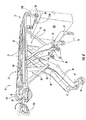
- the roll-in cot 10 comprises a wheel alignment mechanism 300.
- the wheel alignment mechanism 300 provides automatic vertical positioning of the front wheel linkage 27 as the front legs 20 are raised and lowered. By positioning the front wheel linkage 27 in the appropriate orientation, predictable rolling of the roll-in cot 10 can be achieved with the front legs 20 positioned in any of a variety of positions from fully raised to fully lowered, and intermediate positions therebetween. While specific discussion is made herein and describes positioning of the wheel alignment mechanism relative to the front legs 20 of the roll-in cot 10, it should be understood that a roll-in cot 10 according to the present disclosure may incorporate wheel alignment mechanisms 300 into any extendible leg assembly including, for example, back legs 40. Accordingly, “first” and “second” may be used interchangeably herein with “front” or “back” when describing the legs, hinge members, wheel linkages, and wheel alignment mechanisms of the roll-in cot 10 without regard to the positioning of a particular component.
- the front leg 20 and the front hinge member 24 are coupled to one another and pivot relative to one another during raising and lowering operations of the front leg 20.
- the front leg 20 is coupled to the support frame 12 through a carriage 28 ( FIG. 8 ), which allows the front leg 20 to slide in a longitudinal direction relative to the support frame 12 and rotate relative to the support frame 12.
- the front hinge member 24 is coupled to the support frame 12 and the front leg 20, and allowed to pivot relative to the support frame 12 and the front leg. Because the degrees of freedom of movement of the front leg 20 and the hinge member 24 are limited, the front leg 20 and the hinge member 24 move according to a pre-defined kinematic relationship relative to the support frame 12 and to each other when the front leg 20 undergoes a raising or lowering operation.
- This relative angular rotation between the front leg 20 and the hinge member 24 may be predictable and repeatable.
- the relative angular rotation between the front leg 20 and the hinge member 24 may be generally constant (for example, within about 10%) over the stroke of front leg 20 as the front leg moves from a fully-retracted position to a fully-extended position.
- the relative angular rotation between the front leg 20 and the hinge member 24 may vary over the stroke of the front leg 20.
- Wheel alignment mechanisms 300 maintain the angular inclination of the front wheel linkage 27 relative to the ground surface over the stroke of the front leg 20 as the front leg moves from a fully-retracted position to a fully-extended position.
- the relative positioning and coupling of the support frame 12, the front leg 20, and the front hinge member 24 defines a kinematic relationship between the front leg 20 and the front hinge member 24 that causes the front leg 20 and the front hinge member 24 to move with relative angular rotation between one another as the front leg 20 moves between a fully-extended position and a fully-retracted position.
- This relative angular rotation between the front leg 20 and the front hinge member 24 may be calculated based on the positioning of the front leg 20 and the front hinge member 24 relative to the support frame 12.
- the front hinge member 24 moves relative to the front leg 20 to a degree that is greater than the front leg 20 moves relative to the support frame 12. In the embodiment depicted in FIG.
- the front hinge 20 moves at an average relative angular rotation to the front leg 20 that is about twice the movement of the front leg 20 relative to the support frame 12, when evaluated over the stroke of the front leg from the fully-retracted position to the fully-extended position.
- roll-in cots 10 may incorporate a variety of relative angular rotation values.
- the wheel alignment mechanism 300 may include elements that account for the relative angular rotation of the front leg 20 and the front hinge member 24.
- the wheel alignment mechanism 300 includes a timing member 130 disposed within at least a portion of a front leg 20.
- the timing member 130 is a timing belt that is frictionally engaged with hub set members that are positioned within the front leg 20.
- the timing member 130 may have a variety of configurations.
- the timing belt is engaged with hubs 132 that are pivotingly coupled to components of the front leg 20.
- a first hub 132a is coupled to the front hinge member 24, such that as the front leg 20 is raised and lowered, the first hub 132a is held fixed in position relative to the front hinge member 24 and rotates relative to the front leg 20.
- the first hub 132a modifies the position of the timing belt relative to the front leg 20 as the front leg 20 moves between a fully-raised position and a fully-lowered position.
- a second hub 132b is coupled to the front wheel linkage 27.
- the second hub 132b is held fixed in position relative to the front wheel linkage 27 and rotates relative to the front leg 20.
- the timing belt rotates the position of the front wheel linkage 27.
- the first hub 132a and the second hub 132b therefore, modify the position of the timing belt to reposition the orientation of the front wheel linkage 27 as the front leg 20 moves between a fully-retracted position and a fully-lowered position.
- the timing belt and the first hub 132a and the second hub 132b may have a variety of mating interface configurations.
- the timing belt the first hub 132a, and the second hub 132b are grooved at their interface surfaces.
- alternative embodiments of the interface between the timing belt and the first hub 132a and the second hub 132b such as a flat interface or a "vee" interface, are contemplated.
- the timing belt may be constructed from a variety of materials including polymers and elastomers.
- the timing belt may also be reinforced with various materials that are conventionally known for increasing the strength and/or durability of belts, including nylon, polyester, aramids, and the like.
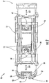
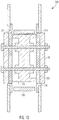
- a hub portion 230 of the front leg 20 is depicted.
- the hub portion 230 provides the interface between the components of the hubs 132 and the front leg 20.
- the hub portion 230 connects the first hub 132a to the front hinge member 24 through the front leg 20.
- a similar hub portion may connect the second hub 132b to the front wheel linkage 27 (see FIG. 9 ).
- the hub portion 230 includes the first hub 132a which is partially encapsulated outer races 234. In some embodiments, the outer races 234 may be integrated into the front leg 20.
- the hub portion 230 may include a plurality of cover plates 232 that are positioned inside the outer races 234, thereby allowing the first hub 132a to rotate within the outer races 234.
- the front hinge member 24 is coupled to the first hub 132a, for example, by fasteners 238 passing through the front hinge member 24, the cover plates 232, and the first hub 132a.
- the hub portion 230 maintains alignment of the first hub 132a relative to the front hinge member 24, such that as the front hinge member 24 pivots relative to the front leg 20, the first hub 132a pivots relative to the upper leg 20 at the same rate as the front hinge member 24.
- the front hinge member 24 pivots relative to the front leg 20, causing the first hub 132a to pivot with respect to the front leg 20.
- the timing belt is drawn by the first hub 132a in one of two directions and communicates the rotation of the first hub 132a relative to the front leg 24 to the second hub 132b, which is similarly engaged with the timing belt.
- the second hub 132b is coupled to the front wheel linkage 27, such that rotation of the second hub 132b changes the orientation of the front wheel linkage 27 relative to the front leg 20.
- the first hub 132a has a smaller diameter than the second hub 132b such that the rotation of the first hub 132a is reduced as compared to the second hub 132b.
- the wheel alignment mechanism therefore, has a reduction ratio that is equivalent to the ratio of the diameter of the first hub 132a to the second hub 132b.
- the ratio of the diameter of the first hub 132a to the second hub 132b is approximately inverse to the relative angular motion between the front leg 20 and the front hinge member 24.
- the angular inclination of the front wheel linkage 27 is controlled by the front leg 20 and the front hinge member 24, as well as by the first hub 132a and the second hub 132b of the wheel alignment mechanism 300, maintaining an inverse relationship between the ratio of diameters of the first hub 132a and the second hub 132b and the relative angular motion between the front leg 20 and the front hinge member 24 may maintain an orientation of the front wheel linkage 27 relative to a horizontal ground surface as the front legs 20 move between a full-retracted position and a fully-extended position.
- the first hub 132a is about half the diameter of the second hub 132b that is coupled to the front wheel linkage 27.
- This corresponds to a front leg 20 and a front hinge member 24 that have a relative angular motion of about 2:1.
- a rotation ⁇ 1 of the front hinge member 24 relative to the front leg 20 causes a rotation ⁇ 2 of the front wheel linkage 27 relative to the front leg 20, where rotation ⁇ 2 is half the magnitude of rotation ⁇ 1.
- the front hinge member 24 rotates 10° relative to the front leg 20
- the front wheel linkage 27 will rotate 5° relative to the front leg 20, which is due to the relative size of the diameters of the first hub 132a and the second hub 132b.
- first hubs 132a and second hubs 132b having a diameter ratio of 1:2
- any of a variety of diameter ratios of first hubs 132a and second hubs 132b may be selected to provide the desired ratio of rotation between the front hinge member 24 and the front wheel linkage 27.
- the diameter ratio of the first hubs 132a and the second hubs 132b may be inverse to the relative angular rotation provided by the front leg 20 and the front hinge member 24.
- the product of the diameter ratio of the first hubs 132a and the second hubs 132b and the relative angular rotation of the front leg 20 and the front hinge member 24 may be within about 30% of unity, including, for example, being within about 25% of unity, for example, being within about 20% of unity, for example, being within about 15% of unity, for example, being within about 10% of unity, for example, being within about 5% of unity.
- the lower the value of the product between the diameter ratio and the relative angular rotation may indicate that the relative angular inclination of the front wheel linkage 27 to a horizontal ground surface is more uniform through the stroke of the front leg 20 from the fully-retracted position to the fully-extended position.
- a roll-in cot 10 having the wheel alignment mechanisms 300 may have a front wheel linkage 27 that positions front wheels 26 in an angular inclination over a variety of orientations of the front legs 20.
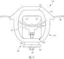
- the wheel alignment mechanism 300 may include at least one shock absorber 310.
- the shock absorber 310 is positioned relative to the timing belt and reduces impact loading applied to the timing belt, for example when the front wheels 26 contact an obstacle.
- the shock absorber 310 includes a housing 312 having an opening 314 to accommodate a tensioner 318, and a belt relief channel 316.
- the tensioner 318 includes a belt channel 319 and is positioned within the opening 314 of the housing 312.
- the shock absorber 310 also includes a damping assembly 320 that includes a tension member 322, a load dispersing element 324, and a compliant bushing 326.
- the tension member 322 is a threaded fastener that secures the damping assembly 320 to the follower 318.
- the shock absorber 310 may also include a plurality of cover plates 317 positioned along the outside of the housing 312 to enclose the shock absorber 310.
- the tensioner 318 is positioned within the opening 314 of the housing 312, and the tensioner 318 is secured to the housing 312 by the tensioner member 322.
- the timing belt is introduced along the belt relief 316 of the housing 312 and along the belt channel 319 of the tensioner 318.
- the path length of the timing belt through the shock absorber 310 is greater than the linear distance along the belt relief 316 of the housing 312, such that the effective length of the timing belt (i.e., the distance traveled by the timing belt evaluated around the first hub 132a and the second hub 132b, as depicted in FIG. 9 ) is decreased upon installation of the shock absorber 310.
- the damping assembly 320 of the shock absorber 310 includes a compliant bushing 326.
- the compliant bushing 326 may be made from a variety of materials including natural or synthetic elastomers.
- at least one mechanical spring (not shown) may be arranged within the shock absorber 310 and perform the same functions as the compliant bushing 326 discussed herein.
- the tension member 322 may be adjusted to provide a pre-determined deformation of the compliant bushing 326, such that variations in the size or material properties of the compliant bushing 326 can be accommodated without adversely affecting performance of the shock absorber 310.
- the front wheel linkage 27 of the roll-in cot 10 is configured to be repositionable in its vertical orientation, such that alignment of the front wheels 26 is maintained over a variety of positions of the front legs 20.
- the front wheels 26 contact an obstacle, for example, when the roll-in cot 10 is being moved, contact between the front wheels 26 and the obstacle may tend to shift the vertical orientation of the front wheel linkage 27 relative to the front legs 20.
- Rotational orientation of the front wheel linkage 27 is arrested by the interaction between the second hub 132b, the timing belt, the first hub 132a, and the front hinge member 24.
- impact between the front wheels 26 and an obstacle may induce a force into the timing belt. The magnitude of the force may tend to overload the timing belt, if the timing belt is not fitted with a shock absorber 310 as discussed hereinabove.
- the compliant bushing 326 deforms.
- the timing belt positioned within the shock absorber 310 tends to "straighten” such that the tensioner 318 draws the load dispersing element 324 in a direction towards the housing 312.
- the compliant bushing 326 deforms, thereby absorbing at least a portion of the impulse load.
- the material, cross-sectional area, and thickness of the compliant bushing 326 may be selected such that a pre-determined impulse load, for example, an impact load associated with one of the front wheels 26 contacting an obstacle such as a curb while the roll-in cot 10 is moving at a brisk walking pace with a patient weighing 249,48 kg (550 pounds) positioned in a supine position on the roll-in cot 10 will tend to deform the compliant bushing 326 without a tensile overload of the timing belt.
- timing belt may be designed to have a safety factor of approximately 50% over this load case such that in the event of the introduction of such an impact event as described hereinabove, the timing belt will maintain structural integrity.
- components of the shock absorber 310 deform to dissipate force in the timing belt associated with the front wheels 26 impacting an obstacle.
- Embodiments of the roll-in cot 10 may include a plurality of shock absorbers 310 positioned along opposite sides of the timing belt.
- the upper shock absorber 310a will absorb impact loads associated with the roll-in cot 10 moving in a forward direction (i.e., loads that tend to increase the length of the timing belt positioned relative to the upper shock absorber 310a), while the lower shock absorber 310b will absorb impact loads associated with the roll-in cot 10 moving in a rearwards direction (i.e., loads that tend to increase the length of the timing belt positioned relative to the lower shock absorber 310b).
- the wheel alignment mechanism 300 may also include at least one idler roller 330.
- the idler roller 330 contacts the timing belt and allows the timing belt to change planar orientations, such that the timing belt may continue to engage the first hub 132a and the second hub 132b in applications in which the first hub 132a and the second hub 132b do not have line-of-sight clearance.
- the idler roller 330 may include a roller mounted on a bearing that is secured to the front leg 20 and configured to rotate while imputing minimum friction to the wheel alignment mechanism 300.
- both of the front legs 20 comprise a wheel alignment mechanism 300 as discussed hereinabove.
- raising or lowering the front end 17 of the support frame 12 by the front legs 20 trigger the rotation of the front wheel linkage 27.
- the back legs 40 may comprise a wheel alignment mechanism 300 similar to that discussed in regard to the front legs 20, wherein the raising or lowering of the back end 19 of the support frame 12 by the back legs 40 triggers the rotation of the back wheel linkage 47.
- vertical orientation of the front wheels 26 and back wheels 46 can be maintained to ensure that the roll-in cot 10 can roll across surfaces of various cot heights.
- the roll-in cot 10 may be rolled in the fore/aft direction and/or side to side at any height when the support frame 12 is substantially parallel to the ground, i.e., the front legs 20 and the back legs 40 are actuated to substantially the same length. Further, by maintaining the vertical orientation of the front wheel linkage 27 and the back wheel linkage 47 relative to the ground, the roll-in cot 10 may be rolled in the fore/aft direction and/or side to side when the support frame 12 is substantially parallel to the ground, and the front legs 20 and the back legs 40 are actuated to different lengths.
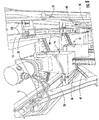
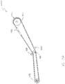
- other embodiments of the roll-in cot may include a wheel alignment mechanism 400 having a timing mechanism 130 that is a timing chain 410.
- the timing chain 410 is coupled to a first hub 414 positioned proximate to the support frame (shown in FIG. 1 ) and a second hub 412 positioned proximate to one of the front wheels or the rear wheels (shown in FIG. 1 ).
- the first hub 414 and the second hub 412 are positioned within one of the front legs or the rear legs (shown in FIG. 1 ) of the roll-in cot. Similar to the embodiment of the roll-in cot incorporating the timing belt described hereinabove in regard to FIGS.
- the timing chain 410 maintains the rotational orientation of the front wheels or the rear wheels relative to the support frame of the roll-in cot so that the rotational clocking orientation of the wheels relative to the ground surface upon which the roll-in cot traverses is maintained for all orientations of the front legs or the rear legs through their range of motion.
- the first hub 414 may be positioned at a variety of positions along the front or rear legs. Rotation of the first hub 414 may account for the positioning of the first hub 414 as to maintain the rotational clocking orientation of the wheels of the roll-in cot.
- Maintaining the radial orientation of the front wheels and the rear wheels may assist with mobility of the roll-in cot when the legs are positioned in a variety of orientations.
- steering of the roll-in cot may be adversely affected if the front wheels or the rear wheels are rotated out of alignment. Maintaining alignment of the front wheels and the rear wheels, therefore, may improve the handling characteristics of the roll-in cot.
- the alignment mechanism 400 includes the timing chain 410 coupled to both the first hub 414 and the second hub 412.
- the timing chain 410 includes a link coupler 416 that joins the timing chain 410 onto itself so that the timing chain 410 is continuous around its perimeter.
- the link coupler 416 may adjust the length of the timing chain 410 so that the timing chain 410 may be adjusted to accommodate variations in distance between the first hub 414 and the second hub 412.
- the alignment mechanism 410 may also include chain tensioners 418, 420 that modify the position of the timing chain 410 as to increase the path distance of the timing chain 410 evaluated around the first hub 414 and the second hub 412. By increasing the path distance of the timing chain 410 around the first hub 414 and the second hub 412, the effective length of the timing chain 410 may be reduced, thereby increasing tension on the timing chain 410.
- the chain tensioners 418, 420 may include a spring mechanism that automatically modifies the path length of the timing chain 410 to account for relative translational movement between the first hub 414 and the second hub 412.
- the chain tensioners 418, 410 may absorb shock loads imparted to the timing chain 410 by temporarily allowing the timing chain 410 to translate the chain tensioner 418,420, thereby temporarily decreasing the path length of the timing chain 410.
- other embodiments of the roll-in cot 10 may include an alignment mechanism 410 having idler rollers 480 (analogous to the idler rollers 330 described hereinabove) that modify the orientation of the timing chain 410 but do not actively modify the tension induced into the timing chain 410.
- the idler rollers 480 may position the timing chain 410 to avoid contact with elements of the cot legs to prevent inadvertent contact between the timing chain 410 and the cot legs.
- the timing chain 410 includes a plurality of links 430 adjoined to one another to form the timing chain 410.
- the timing chain 410 is a block chain, however other types of chains may be suitable for the instant design without departing from the scope of the present disclosure, including roller chains.
- the timing chain 410 is generally fixed in orientation to the first hub 414 and the second hub 412 (see FIG. 12 ) to maintain the rotational clocking orientations of the first hub 414 and the second hub 412.
- the orientation of the timing chain 410 relative to the first hub 414 and the second hub 412 is generally fixed so that the meshing of the timing chain 410 with the first hub 414 and the second hub 412 is not modified.
- other embodiments of the alignment mechanism 400 may incorporate first and second hubs 414, 412 and a timing chain 410 whose meshing is modified over in operation.
- the timing chain 410 includes a first hub mating portion 432 that is coupled to the first hub 414 (shown in FIG. 12 ).
- the first hub mating portion 432 includes a plurality of attachment plates 436, 438 that are pinned to one another to form the first hub mating portion 432.
- the attachment plates 436, 438 correspond in general thickness to the links 430 that make up remaining portions of the timing chain 410, so that the first hub mating portion 432 may be easily integrated into the timing chain 410.
- Each of the attachment plates 436, 438 include at least one through hole 440 that passes through the attachment plates 436, 428.
- the through holes 440 are aligned to allow insertion of a fastener, for example a bolt, screw, or pin.
- the first hub mating portion 432 may thereby be resiliently coupled to the first hub 414 through a fastened connection.
- the second hub 412 includes a first cover plate 452 and a second cover plate 454 that are positioned opposite one another along the ends of the second hub 412.
- the second hub 412 also includes a plurality of attachment plates 456 and bypass plates 458 that are arranged proximate to one another to form the center portion of the second hub 412.
- the first cover plate 452 of the second hub 412 is removed from the view of FIG. 15 to more clearly depict the attachment plates 456 and the bypass plates 458 of the second hub 412.
- the attachment plates 456 of the second hub 412 each include a securement tab 457 that extends from a clearance portion 459.
- the securement tabs 457 each include at least one through hole 460 through which a fastener, such as a screw, a bolt, or a pin, may be inserted.
- Coupling the timing chain 410 and the attachment plates 456 of the second hub 412 to one another provides a resilient attachment between the timing chain 410 and the second hub 412, thereby allowing the timing chain 410 to maintain the rotational clocking orientation of the first hub 414 and the second hub 412.
- the roll-in cot 10 may comprise a front actuator sensor 62 and a back actuator sensor 64 configured to detect whether the front and back actuators 16, 18 respectively are under tension or compression.
- tension means that a pulling force is being detected by the sensor.
- compression means that a pushing force is being detected by the sensor.
- the front actuator sensor 62 and the back actuator sensor 64 are coupled to the support frame 12; however, other locations or configurations are contemplated herein.
- the sensors may be proximity sensors, strain gauges, load cells, Hall-effect sensors, or any other suitable sensor operable to detect when the front actuator 16 and/or back actuator 18 are under tension or compression.
- the front actuator sensor 62 and the back actuator sensor 64 may be operable to detect the weight of a patient disposed on the roll-in cot 10 (e.g., when strain gauges are utilized).
- the movement of the roll-in cot 10 may be controlled via the operator controls.
- the back end 19 may comprise operator controls for the roll-in cot 10.
- the operator controls are the components used by the operator in the loading and unloading of the roll-in cot 10 by controlling the movement of the front legs 20, the back legs 40, and the support frame 12.
- the operator controls may comprise one or more hand controls 57 (for example, buttons on telescoping handles) disposed on the back end 19 of the roll-in cot 10.
- the operator controls may include a control box 50 disposed on the back end 19 of the roll-in cot 10, which is used by the cot to switch from the default independent mode and the synchronized or "sync" mode.
- the control box 50 may comprise one or more buttons 54, 56 which place in the cot in sync mode, such that both the front legs 20 and back legs 40 can be raised and lowered simultaneously.
- the sync mode may only be temporary and cot operation will return to the default mode after a period of time, for example, about 30 seconds.
- the sync mode may be utilized in loading and/or unloading the roll-in cot 10. While various positions are contemplated, the control box may be disposed between the handles on the back end 19.
- the control box 50 may also include a component which may be used to raise and lower the roll-in cot 10.
- the component is a toggle switch 52, which is able to raise (+) or lower (-) the cot.
- Other buttons, switches, or knobs are also suitable.
- the toggle switch 52 may be used to control the front legs 20 or back legs 40 which are operable to be raised, lowered, retracted or released depending on the position of the roll-in cot 10.
- the toggle switch is analog (i.e., the pressure and/or displacement of the analog switch is proportional to the speed of actuation).
- the operator controls may comprise a visual display component 58 configured to inform an operator whether the front and back actuators 16, 18 are activated or deactivated, and thereby may be raised, lowered, retracted or released. While the operator controls are disposed at the back end 19 of the roll-in cot 10 in the present embodiments, it is further contemplated that the operator controls be positioned at alternative positions on the support frame 12, for example, on the front end 17 or the sides of the support frame 12. In still further embodiments, the operator controls may be located in a removably attachable wireless remote control that may control the roll-in cot 10 without physical attachment to the roll-in cot 10.
- the roll-in cot 10 may further comprise a light strip 140 configured to illuminate the roll-in cot 10 in poor lighting or poor visibility environments.
- the light strip 140 may comprise LED's, light bulbs, phosphorescent materials, or combinations thereof.
- the light strip 140 may be triggered by a sensor which detects poor lighting or poor visibility environments.
- the cot may also comprise an on/off button or switch for the light strip 140. While the light strip 140 is positioned along the side of the support frame 12 in the embodiment of FIG. 4 , it is contemplated that the light strip 140 could be disposed on the front and/or back legs 20, 40, and various other locations on the roll-in cot 10.
- the light strip 140 may be utilized as an emergency beacon analogous to ambulance emergency lights.
- an emergency beacon is configured to sequence the warning lights in a manner that draws attention to the emergency beacon and that mitigates hazards such as, for example photosensitive epilepsy, glare and phototaxis.
- front actuator sensor 62 and back actuator sensor 64 detect that the front actuator 16 and the back actuator 18 are under compression, i.e., the front legs 20 and the back legs 40 are in contact with a lower surface and are loaded.
- the front and back actuators 16 and 18 are both active when the front and back actuator sensors 62, 64 detect both the front and back actuators 16, 18, respectively, are under compression and can be raised or lowered by the operator using the operator controls as shown in FIG. 2 (e.g., "-" to lower and "+” to raise).
- the roll-in cot 10 comprises a support frame 12 slidingly engaged with a pair of front legs 20 and a pair of back legs 40.
- Each of the front legs 20 are rotatably coupled to a front hinge member 24 that is rotatably coupled to the support frame 12 (e.g., via carriage members 28, 48 ( FIG. 8 )).
- Each of the back legs 40 are rotatably coupled to a back hinge member 44 that is rotatably coupled to the support frame 12.
- the front hinge members 24 are rotatably coupled towards the front end 17 of the support frame 12 and the back hinge members 44 that are rotatably coupled to the support frame 12 towards the back end 19.
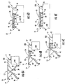
- FIG. 5A depicts the roll-in cot 10 in a lowest transport position (e.g., the back wheels 46 and the front wheels 26 are in contact with a surface, the front leg 20 is slidingly engaged with the support frame 12 such that the front leg 20 contacts a portion of the support frame 12 towards the back end 19 and the back leg 40 is slidingly engaged with the support frame 12 such that the back leg 40 contacts a portion of the support frame 12 towards the front end 17).
- FIG. 5B depicts the roll-in cot 10 in an intermediate transport position, i.e., the front legs 20 and the back legs 40 are in intermediate transport positions along the support frame 12.
- 5C depicts the roll-in cot 10 in a highest transport position, i.e., the front legs 20 and the back legs 40 positioned along the support frame 12 such that the front load wheels 70 are at a maximum desired height which can be set to height sufficient to load the cot, as is described in greater detail herein.
- the embodiments described herein may be utilized to lift a patient from a position below a vehicle in preparation for loading a patient into the vehicle (e.g., from the ground to above a loading surface of an ambulance).
- the roll-in cot 10 may be raised from the lowest transport position ( FIG. 5A ) to an intermediate transport position ( FIG. 5B ) or the highest transport position ( FIG. 5C ) by simultaneously actuating the front legs 20 and back legs 40 and causing them to slide along the support frame 12.
- the actuation causes the front legs to slide towards the front end 17 and to rotate about the front hinge members 24, and the back legs 40 to slide towards the back end 19 and to rotate about the back hinge members 44.
- a user may interact with a control box 50 ( FIG.
- the roll-in cot 10 is raised from its current position (e.g., lowest transport position or an intermediate transport position) until it reaches the highest transport position. Upon reaching the highest transport position, the actuation may cease automatically, i.e., to raise the roll-in cot 10 higher additional input is required. Input may be provided to the roll-in cot 10 and/or control box 50 in any manner such as electronically, audibly or manually.
- the roll-in cot 10 may be lowered from an intermediate transport position ( FIG. 5B ) or the highest transport position ( FIG. 5C ) to the lowest transport position ( FIG. 5A ) by simultaneously actuating the front legs 20 and back legs 40 and causing them to slide along the support frame 12. Specifically, when being lowered, the actuation causes the front legs to slide towards the back end 19 and to rotate about the front hinge members 24, and the back legs 40 to slide towards the front end 17 and to rotate about the back hinge members 44.
- a user may provide input indicative of a desire to lower the roll-in cot 10 (e.g., by pressing a "-"on toggle switch 52).
- the roll-in cot 10 Upon receiving the input, the roll-in cot 10 lowers from its current position (e.g., highest transport position or an intermediate transport position) until it reaches the lowest transport position. Once the roll-in cot 10 reaches its lowest height (e.g., the lowest transport position) the actuation may cease automatically.
- the control box 50 FIG. 1 ) provides a visual indication that the front legs 20 and back legs 40 are active during movement.
- the front legs 20 are in contact with the support frame 12 at a front-loading index 221 and the back legs 40 are in contact with the support frame 12 a back-loading index 241. While the front-loading index 221 and the back-loading index 241 are depicted in FIG. 5C as being located near the middle of the support frame 12, additional embodiments are contemplated with the front-loading index 221 and the back-loading index 241 located at any position along the support frame 12.
- the highest transport position may be set by actuating the roll-in cot 10 to the desired height and providing input indicative of a desire to set the highest transport position (e.g., pressing and holding the "+” and "-” on toggle switch 52 simultaneously for 10 seconds).
- any time the roll-in cot 10 is raised over the highest transport position for a set period of time e.g., 30 seconds
- the control box 50 provides an indication that the roll-in cot 10 has exceeded the highest transport position and the roll-in cot 10 needs to be lowered.
- the indication may be visual, audible, electronic or combinations thereof.
- the front legs 20 When the roll-in cot 10 is in the lowest transport position ( FIG. 5A ), the front legs 20 may be in contact with the support frame 12 at a front-flat index 220 located near the back end 19 of the support frame 12 and the back legs 40 may be in contact with the support frame 12 a back-flat index 240 located near the front end 17 of the support frame 12.
- index means a position along the support frame 12 that corresponds to a mechanical stop or an electrical stop such as, for example, an obstruction in a channel formed in a lateral side member 15, a locking mechanism, or a stop controlled by a servomechanism.
- the front actuator 16 is operable to raise or lower a front end 17 of the support frame 12 independently of the back actuator 18.
- the back actuator 18 is operable to raise or lower a back end 19 of the support frame 12 independently of the front actuator 16.
- the roll-in cot 10 is able to maintain the support frame 12 level or substantially level when the roll-in cot 10 is moved over uneven surfaces, for example, a staircase or hill.
- the set of legs not in contact with a surface i.e., the set of legs that is in tension
- the roll-in cot 10 e.g., moving the roll-in cot 10 off of a curb.
- roll-in cot 10 are operable to be automatically leveled. For example, if back end 19 is lower than the front end 17, pressing the "+" on toggle switch 52 raises the back end 19 to level prior to raising the roll-in cot 10, and pressing the "-" on toggle switch 52 lowers the front end 17 to level prior to lowering the roll-in cot 10.
- the roll-in cot 10 receives a first load signal from the front actuator sensor 62 indicative of a first force acting upon the front actuator 16 and a second load signal from the front actuator sensor 62 indicative of a second force acting upon a back actuator 18.
- the first load signal and second load signal may be processed by logic executed by the control box 50 to determine the response of the roll-in cot 10 to input received by the roll-in cot 10.
- user input may be entered into the control box 50.
- the user input is received as control signal indicative of a command to change a height of the roll-in cot 10 by the control box 50.
- the front actuator actuates the front legs 20 and the back actuator 18 remains substantially static (e.g., is not actuated). Therefore, when only the first load signal indicates a tensile state, the front legs 20 may be raised by pressing the "-" on toggle switch 52 and/or lowered by pressing the "+" on toggle switch 52.
- the back actuator 18 actuates the back legs 40 and the front actuator 16 remains substantially static (e.g., is not actuated).
- the back legs 40 may be raised by pressing the "-" on toggle switch 52 and/or lowered by pressing the "+” on toggle switch 52.
- the actuators may actuate relatively slowly upon initial movement (i.e., slow start) to mitigate rapid jostling of the support frame 12 prior to actuating relatively quickly.
- independent actuation may be utilized by the embodiments described herein for loading a patient into a vehicle (note that for clarity the front actuator 16 and the back actuator 18 are not depicted in FIGS. 5C-6E ).
- the roll-in cot 10 can be loaded onto a loading surface 500 according the process described below. First, the roll-in cot 10 may be placed into the highest transport position ( FIG. 5C ) or any position where the front load wheels 70 are located at a height greater than the loading surface 500. When the roll-in cot 10 is loaded onto a loading surface 500, the roll-in cot 10 may be raised via front and back actuators 16 and 18 to ensure the front load wheels 70 are disposed over a loading surface 500.
- the front load wheels 70 are over the loading surface 500.
- the front pair of legs 20 can be actuated with the front actuator 16 because the front end 17 is above the loading surface 500.
- the middle portion of the roll-in cot 10 is away from the loading surface 500 (i.e., a large enough portion of the roll-in cot 10 has not been loaded beyond the loading edge 502 such that most of the weight of the roll-in cot 10 can be cantilevered and supported by the wheels 70, 26, and/or 30).
- the roll-in cot 10 may be held level with a reduced amount of force.
- the front actuator 16 is in tension and the back actuator 18 is in compression.
- the front legs 20 are raised ( FIG. 6B ).
- the operation of the front actuator 16 and the back actuator 18 is dependent upon the location of the roll-in cot.
- a visual indication is provided on the visual display component 58 of the control box 50 ( FIG. 2 ).
- the visual indication may be color-coded (e.g., activated legs in green and non-activated legs in red).
- This front actuator 16 may automatically cease to operate when the front legs 20 have been fully retracted.
- the front actuator sensor 62 may detect tension, at which point, front actuator 16 may raise the front legs 20 at a higher rate, for example, fully retract within about 2 seconds.
- the roll-in cot 10 may be urged forward until the intermediate load wheels 30 have been loaded onto the loading surface 500 ( FIG. 6C ).
- the front end 17 and the middle portion of the roll-in cot 10 are above the loading surface 500.
- the pair of back legs 40 can be retracted with the back actuator 18.
- an ultrasonic sensor may be positioned to detect when the middle portion is above the loading surface 500.
- the back actuator may be actuated.
- an indication may be provided by the control box 50 ( FIG. 2 ) when the intermediate load wheels 30 are sufficiently beyond the loading edge 502 to allow for back leg 40 actuation (e.g., an audible beep may be provided).
- the middle portion of the roll-in cot 10 is above the loading surface 500 when any portion of the roll-in cot 10 that may act as a fulcrum is sufficiently beyond the loading edge 502 such that the back legs 40 may be retracted a reduced amount of force is required to lift the back end 19 (e.g., less than half of the weight of the roll-in cot 10, which may be loaded, needs to be supported at the back end 19).
- the detection of the location of the roll-in cot 10 may be accomplished by sensors located on the roll-in cot 10 and/or sensors on or adjacent to the loading surface 500. For example, an ambulance may have sensors that detect the positioning of the roll-in cot 10 with respect to the loading surface 500 and/or loading edge 502 and communications means to transmit the information to the roll-in cot 10.
- the back actuator sensor 64 may detect that the back legs 40 are unloaded, at which point, the back actuator 18 may raise the back legs 40 at higher speed.
- the back actuator 18 may automatically cease to operate.
- an indication may be provided by the control box 50 ( FIG. 2 ) when the roll-in cot 10 is sufficiently beyond the loading edge 502 (e.g., fully loaded or loaded such that the back actuator is beyond the loading edge 502).
- the front and back actuators 16, 18 may be deactivated by being lockingly coupled to an ambulance.
- the ambulance and the roll-in cot 10 may each be fitted with components suitable for coupling, for example, male-female connectors.
- the roll-in cot 10 may comprise a sensor which registers when the cot is fully disposed in the ambulance, and sends a signal which results in the locking of the actuators 16, 18.
- the roll-in cot 10 may be connected to a cot fastener, which locks the actuators 16, 18, and is further coupled to the ambulance's power system, which charges the roll-in cot 10.
- ICS Integrated Charging System
- independent actuation may be utilized by the embodiments described herein for unloading the roll-in cot 10 from a loading surface 500.
- the roll-in cot 10 may be unlocked from the fastener and urged towards the loading edge 502 ( FIG. 6E to FIG. 6D ).
- the back actuator sensor 64 detects that the back legs 40 are unloaded and allows the back legs 40 to be lowered.
- the back legs 40 may be prevented from lowering, for example if sensors detect that the cot is not in the correct location (e.g., the back wheels 46 are above the loading surface 500 or the intermediate load wheels 30 are away from the loading edge 502).
- an indication may be provided by the control box 50 ( FIG. 2 ) when the back actuator 18 is activated (e.g., the intermediate load wheels 30 are near the loading edge 502 and/or the back actuator sensor 64 detects tension).
- the back legs 40 can be extended ( FIG. 6C ).
- the back legs 40 may be extended by pressing the "+" on toggle switch 52.
- a visual indication is provided on the visual display component 58 of the control box 50 ( FIG. 2 ).
- a visual indication may be provided when the roll-in cot 10 is in a loading state and the back legs 40 and/or front legs 20 are actuated. Such a visual indication may signal that the roll-in cot should not be moved (e.g., pulled, pushed, or rolled) during the actuation.
- the back legs 40 contact the floor ( FIG. 6C )
- the back legs 40 become loaded and the back actuator sensor 64 deactivates the back actuator 18.
- the front actuator 16 When a sensor detects that the front legs 20 are clear of the loading surface 500 ( FIG. 6B ), the front actuator 16 is activated. In one embodiment, when the intermediate load wheels 30 are at the loading edge 502 an indication may be provided by the control box 50 ( FIG. 2 ). The front legs 20 are extended until the front legs 20 contact the floor ( FIG. 6A ). For example, the front legs 20 may be extended by pressing the "+" on toggle switch 52. In one embodiment, upon the front legs 20 lowering, a visual indication is provided on the visual display component 58 of the control box 50 ( FIG. 2 ).
- the hook engagement bar 80 is operable to engage with a loading surface hook 550 on a loading surface 500
- the hook engagement bar 80 is disengaged prior to unloading the roll-in cot 10.
- hook engagement bar 80 may be rotated to avoid the loading surface hook 550.
- the roll-in cot 10 may be raised from the position depicted in FIG. 4 such that the hook engagement bar 80 avoids the loading surface hook 550.
- the roll-in cot includes a wheel alignment mechanism incorporated into the front legs, the wheel alignment mechanism controlling the vertical orientation of the at least one front wheel.
- the wheel alignment mechanism includes at least one shock absorber that absorbs an impact load applied to the at least one front wheel
- the term “substantially” is utilized herein to represent the inherent degree of uncertainty that may be attributed to any quantitative comparison, value, measurement, or other representation.
- the term “substantially” is also utilized herein to represent the degree by which a quantitative representation may vary from a stated reference without resulting in a change in the basic function of the subject matter at issue.
Landscapes
- Health & Medical Sciences (AREA)
- Life Sciences & Earth Sciences (AREA)
- Animal Behavior & Ethology (AREA)
- General Health & Medical Sciences (AREA)
- Public Health (AREA)
- Veterinary Medicine (AREA)
- Invalid Beds And Related Equipment (AREA)
- Handcart (AREA)
- Devices For Conveying Motion By Means Of Endless Flexible Members (AREA)
- Rehabilitation Tools (AREA)
Priority Applications (1)
| Application Number | Priority Date | Filing Date | Title |
|---|---|---|---|
| PL14712076T PL2961368T3 (pl) | 2013-02-27 | 2014-02-27 | Nosze składane na kółkach z napędem i mechanizmem wyrównywania kółek |
Applications Claiming Priority (3)
| Application Number | Priority Date | Filing Date | Title |
|---|---|---|---|
| US201361769918P | 2013-02-27 | 2013-02-27 | |
| US201361835042P | 2013-06-14 | 2013-06-14 | |
| PCT/US2014/019056 WO2014134321A1 (en) | 2013-02-27 | 2014-02-27 | Powered roll-in cots having wheel alignment mechanisms |
Publications (2)
| Publication Number | Publication Date |
|---|---|
| EP2961368A1 EP2961368A1 (en) | 2016-01-06 |
| EP2961368B1 true EP2961368B1 (en) | 2018-06-06 |
Family
ID=50346100
Family Applications (1)
| Application Number | Title | Priority Date | Filing Date |
|---|---|---|---|
| EP14712076.0A Active EP2961368B1 (en) | 2013-02-27 | 2014-02-27 | Powered roll-in cots having wheel alignment mechanisms |
Country Status (12)
| Country | Link |
|---|---|
| US (2) | US9999555B2 (pl) |
| EP (1) | EP2961368B1 (pl) |
| JP (3) | JP6636333B2 (pl) |
| KR (2) | KR20190124328A (pl) |
| CN (2) | CN107349057B (pl) |
| AU (2) | AU2014223409B9 (pl) |
| BR (1) | BR112015020498A2 (pl) |
| CA (1) | CA2902478C (pl) |
| DK (1) | DK2961368T3 (pl) |
| ES (1) | ES2681600T3 (pl) |
| PL (1) | PL2961368T3 (pl) |
| WO (1) | WO2014134321A1 (pl) |
Families Citing this family (24)
| Publication number | Priority date | Publication date | Assignee | Title |
|---|---|---|---|---|
| KR20190129144A (ko) | 2010-01-13 | 2019-11-19 | 페르노-와싱턴, 인코포레이티드. | 전동식 롤인 간이침대 |
| US9510982B2 (en) | 2010-01-13 | 2016-12-06 | Ferno-Washington, Inc. | Powered roll-in cots |
| DK2874589T3 (en) | 2012-07-20 | 2017-12-04 | Ferno Washington Inc | AUTOMATED SYSTEMS FOR MOTORIZED CARRIERS |
| JP2017509441A (ja) * | 2014-04-04 | 2017-04-06 | ファーノ−ワシントン・インコーポレーテッド | 自動的な連結式簡易ベッドのための方法及びシステム |
| CA2945163C (en) | 2014-04-24 | 2020-08-18 | Ferno-Washington, Inc. | Loading platform alignment system and loading/unloading method thereof |
| US20170035628A1 (en) * | 2014-07-07 | 2017-02-09 | Stryker Corporation | Patient support |
| US9456938B2 (en) | 2014-11-11 | 2016-10-04 | Ferno-Washington, Inc. | Powered ambulance cot with an automated cot control system |
| WO2018009587A1 (en) * | 2016-07-05 | 2018-01-11 | Orbis Wheels, Inc. | Multi-wheel transmission |
| US11202729B2 (en) | 2017-06-27 | 2021-12-21 | Stryker Corporation | Patient support apparatus user interfaces |
| US11382812B2 (en) | 2017-06-27 | 2022-07-12 | Stryker Corporation | Patient support systems and methods for assisting caregivers with patient care |
| US11337872B2 (en) | 2017-06-27 | 2022-05-24 | Stryker Corporation | Patient support systems and methods for assisting caregivers with patient care |
| US11304865B2 (en) | 2017-06-27 | 2022-04-19 | Stryker Corporation | Patient support apparatus with adaptive user interface |
| US11484451B1 (en) | 2017-06-27 | 2022-11-01 | Stryker Corporation | Patient support apparatus user interfaces |
| US10811136B2 (en) | 2017-06-27 | 2020-10-20 | Stryker Corporation | Access systems for use with patient support apparatuses |
| US11810667B2 (en) | 2017-06-27 | 2023-11-07 | Stryker Corporation | Patient support systems and methods for assisting caregivers with patient care |
| US11096850B2 (en) | 2017-06-27 | 2021-08-24 | Stryker Corporation | Patient support apparatus control systems |
| CA3188575A1 (en) * | 2018-04-06 | 2019-10-10 | Rite-Hite Holding Corporation | Maneuverable ergonomic trailer stands |
| DE102018109352A1 (de) | 2018-04-19 | 2019-10-24 | HAWE Altenstadt Holding GmbH | Fahrbare Rettungsliege |
| IT201800006240A1 (it) * | 2018-06-12 | 2019-12-12 | Telaio da trasporto e sistema di caricamento per una barella. | |
| US11929157B2 (en) * | 2018-11-02 | 2024-03-12 | Stryker Corporation | Techniques for transporting autonomous patient support apparatuses and medical equipment to an incident scene |
| CN110189888A (zh) * | 2019-05-23 | 2019-08-30 | 洪文敬 | 一种牵引变压器 |
| US11760430B2 (en) * | 2019-11-08 | 2023-09-19 | Jesse James Hahn | Lift assembly for a vehicle |
| CN112274333B (zh) * | 2020-10-14 | 2021-07-30 | 青岛柒有医疗科技有限公司 | 一种新型的医用电动移位车 |
| CN115892730A (zh) * | 2022-12-14 | 2023-04-04 | 上海品兴医疗设备有限公司 | 转运装置 |
Family Cites Families (135)
| Publication number | Priority date | Publication date | Assignee | Title |
|---|---|---|---|---|
| US446666A (en) | 1891-02-17 | Thomas a | ||
| US2204205A (en) | 1937-08-04 | 1940-06-11 | Heywood Wakefield Co | Armrest support |
| US2278749A (en) | 1939-02-09 | 1942-04-07 | American Seating Co | Chair arm |
| US2203204A (en) | 1939-08-19 | 1940-06-04 | Charles O Nicolai | Invalid elevator |
| US2642250A (en) | 1950-03-06 | 1953-06-16 | Anthony M Kasnowich | Arm support for operating beds |
| GB1063614A (en) | 1964-06-03 | 1967-03-30 | Robin Beaufort Bush | Flexible coupling |
| US3544163A (en) | 1968-11-08 | 1970-12-01 | Stitchcraft Corp | Articulated connector |
| SE329467B (pl) | 1969-03-13 | 1970-10-12 | Hydraul Verken Ab | |
| US3612606A (en) | 1970-09-03 | 1971-10-12 | Swenson Corp | Seat having foldable armrests |
| CH582376B5 (pl) | 1973-05-11 | 1976-11-30 | Ebauches Bettlach Sa | |
| JPS51151878U (pl) * | 1975-05-29 | 1976-12-04 | ||
| US4186905A (en) | 1975-06-09 | 1980-02-05 | Dominion Auto Accessories Limited | Retractable truck mirror |
| US3951452A (en) | 1975-08-04 | 1976-04-20 | Coach & Car Equipment Corporation | Breakaway armrest for seat |
| US4037871A (en) | 1976-04-23 | 1977-07-26 | Ferno-Washington, Inc. | Multiple purpose ambulance cot with removable stretcher top |
| US4155588A (en) | 1976-05-03 | 1979-05-22 | Reuven Danziger | Wheelchair |
| US4073538A (en) | 1977-01-03 | 1978-02-14 | Hunter George Taylor | Arm structure for reclining seat |
| US4225183A (en) | 1979-01-11 | 1980-09-30 | Corbin-Gentry, Inc. | Motorcycle seat with pivotable armrests for the passenger |
| US4270798A (en) | 1979-07-10 | 1981-06-02 | Coach & Car Equipment Corporation | Breakaway arm for seat |
| JPS57160415A (en) | 1981-03-26 | 1982-10-02 | Nissan Motor | Seat |
| USD289992S (en) | 1984-07-27 | 1987-05-26 | Colson Equipment, Inc. | Stretcher |
| FR2571958B1 (fr) | 1984-10-18 | 1987-02-20 | Contact Securite Ste Expl | Chariot-brancard a plan de couche adaptable en hauteur |
| US4745647A (en) | 1985-12-30 | 1988-05-24 | Ssi Medical Services, Inc. | Patient support structure |
| DE8627459U1 (de) | 1986-10-15 | 1987-11-19 | Lunke & Sohn Gmbh, 5810 Witten | Türscharnier für eine Fahrzeugtür |
| US4761841A (en) | 1987-05-11 | 1988-08-09 | Larsen Ralph E | Hospital gurney having a patient transfer device |
| DE3734902C1 (de) | 1987-10-15 | 1989-04-13 | Stollenwerk Fabrik Fuer Sanita | Fahrgeraet fuer eine Krankentrage |
| US4767148A (en) | 1987-10-28 | 1988-08-30 | Ferno-Washington, Inc. | Multiple level roll-in cot |
| FR2631548B1 (fr) | 1988-05-19 | 1991-02-22 | Louit Sa | Module autonome de soins intensifs et de reanimation |
| JPH0211955A (ja) * | 1988-06-28 | 1990-01-17 | Koyo Seiko Co Ltd | オートテンショナ |
| JPH02200262A (ja) | 1989-01-31 | 1990-08-08 | Paramaunto Bed Kk | 仰臥台に於ける床部支持フレームの昇降機構及びその昇降機構を備えた仰臥台 |
| NL8901747A (nl) | 1989-07-07 | 1991-02-01 | Ferdinand Willemsen | Wagen met inklapbare poten. |
| US5023968A (en) | 1989-07-11 | 1991-06-18 | Diehl Phillip C | Removable litter chair insert |
| DE3927484C1 (pl) | 1989-08-19 | 1990-10-04 | Stollenwerk Fabrik Fuer Sanitaetsausruestungen Hans Stollenwerk & Cie Gmbh & Co, 5000 Koeln, De | |
| US5088136A (en) | 1990-01-26 | 1992-02-18 | Stryker Corporation | Patient transfer mattress surface |
| US5069465A (en) | 1990-01-26 | 1991-12-03 | Stryker Corporation | Dual position push handles for hospital stretcher |
| US5056805A (en) | 1990-06-05 | 1991-10-15 | Wang Chia Ho | Stroller |
| US5039118A (en) | 1990-08-22 | 1991-08-13 | Huang Ming Tai | Stroller with an improved connector |
| US5062179A (en) | 1991-03-11 | 1991-11-05 | Huang Ming Tai | Handle assembly for doll carriages |
| US5168601A (en) | 1992-07-21 | 1992-12-08 | Liu Kun Hei | Adjustable baby cart handrail positioning device |
| US5265969A (en) | 1992-12-16 | 1993-11-30 | Chuang Ching Pao | Angle-adjustable joint |
| JP3614432B2 (ja) | 1993-01-04 | 2005-01-26 | フェルノ・ワシントン・インコーポレイテッド | アンダーキャリッジ |
| US5971091A (en) | 1993-02-24 | 1999-10-26 | Deka Products Limited Partnership | Transportation vehicles and methods |
| US5586346A (en) | 1994-02-15 | 1996-12-24 | Support Systems, International | Method and apparatus for supporting and for supplying therapy to a patient |
| US5537700A (en) | 1994-04-19 | 1996-07-23 | Stryker Corporation | Emergency stretcher with X-frame support |
| US5431087A (en) | 1994-06-15 | 1995-07-11 | Kambara; Goro | Extended stroke linear actuator assembly |
| US7017208B2 (en) | 1995-08-04 | 2006-03-28 | Hill-Rom Services, Inc. | Hospital bed |
| DE29517605U1 (de) * | 1995-11-07 | 1997-03-13 | Tente-Rollen GmbH & Co, 42929 Wermelskirchen | Laufrolle, insbesondere Lenkrolle |
| US5774914A (en) | 1996-01-05 | 1998-07-07 | Stryker Corporation | Maternity bed |
| US5630428A (en) | 1996-02-02 | 1997-05-20 | Wallace; Ted T. | Spine board limb supporting extension |
| US5720057A (en) | 1996-03-28 | 1998-02-24 | Duncan; James B. | Disaster relief bed |
| US5839136A (en) | 1997-05-23 | 1998-11-24 | Ferno-Washington, Inc. | Cot mountable arm rest and cot incorporating same |
| US5867911A (en) | 1997-07-23 | 1999-02-09 | Mcculloch Corporation | Apparatus for adjusting relative positions of first and second members |
| US5996954A (en) | 1997-10-14 | 1999-12-07 | Rosen Products Llc | Stowable support apparatus |
| FR2783482B1 (fr) | 1998-09-23 | 2000-12-01 | Ampafrance | Poussette pliante, a poignee inclinable et equipee d'une commande de pliage deportee |
| US6299137B1 (en) | 1999-04-28 | 2001-10-09 | Wesley Allen Bainter | Hydraulic grain storage bin lifting system |
| US6352240B1 (en) | 1999-05-13 | 2002-03-05 | Hill-Rom Services, Inc. | Hydraulic control apparatus for a hospital bed |
| GB9915257D0 (en) | 1999-07-01 | 1999-09-01 | Ferno Uk Limited | Improvements in or relating to stretcher trolleys |
| US6330926B1 (en) | 1999-09-15 | 2001-12-18 | Hill-Rom Services, Inc. | Stretcher having a motorized wheel |
| USD454319S1 (en) | 1999-10-12 | 2002-03-12 | Takano Co., Ltd. | Stretcher wheelchair |
| AU2744701A (en) | 1999-12-29 | 2001-07-09 | Hill-Rom Services, Inc. | Hospital bed |
| JP2001197962A (ja) | 2000-01-19 | 2001-07-24 | Yoshinobu Kitada | 寝台を水平に昇降させる油圧装置 |
| EP1698314B1 (en) | 2000-03-17 | 2010-04-21 | Stryker Corporation | Stretcher |
| US6389623B1 (en) | 2000-03-23 | 2002-05-21 | Ferno-Washington, Inc. | Ambulance stretcher with improved height adjustment feature |
| US6405393B2 (en) | 2000-05-01 | 2002-06-18 | Michael W. Megown | Height and angle adjustable bed having a rolling base |
| EP1320348A2 (en) | 2000-09-29 | 2003-06-25 | Carroll Intelli Corp | Height adjustable bed and automatic leg stabilizer system therefor |
| EP1346714A4 (en) | 2000-12-26 | 2006-05-24 | Matunaga Manufactory Co Ltd | stretcher |
| FR2820375B1 (fr) | 2001-02-06 | 2003-04-18 | Faurecia Sieges Automobile | Dispositif de fixation pour accoudoir amovible et dispositif d'assise comportant un tel dispositif de fixation |
| US6503018B2 (en) | 2001-03-15 | 2003-01-07 | Link Treasure Limited | Structure of handlebar joint |
| JP4014814B2 (ja) | 2001-03-30 | 2007-11-28 | スガツネ工業株式会社 | ヒンジ装置 |
| US6654973B2 (en) | 2001-05-24 | 2003-12-02 | Tech Lift, Inc. | Mobile lift-assisted patient transport device |
| US20030025378A1 (en) | 2001-06-21 | 2003-02-06 | Chin-Tao Lin | Turnable armrest for an office chair |
| US6550801B1 (en) | 2001-10-03 | 2003-04-22 | Graco Children's Products Inc. | Adjustable cable compensating knuckle for a stroller |
| CN2524726Y (zh) * | 2001-12-25 | 2002-12-11 | 江阴市万事兴汽车研究所有限公司 | 折叠式推车 |
| CA2438906A1 (en) | 2002-08-30 | 2004-02-29 | Neomedtek, Llc | Transportable medical apparatus |
| AU2003248014B2 (en) | 2002-09-26 | 2008-11-06 | Ferno Australia Pty Ltd | Roll-in Cot |
| JP2005021628A (ja) * | 2003-07-04 | 2005-01-27 | Shin Meiwa Ind Co Ltd | ストレッチャー及びストレッチャーシステム |
| JP2004313737A (ja) * | 2003-03-31 | 2004-11-11 | Shin Meiwa Ind Co Ltd | ストレッチャー及びその使用方法 |
| WO2004087029A1 (ja) | 2003-03-31 | 2004-10-14 | Shinmaywa Industries, Ltd. | ストレッチャー、ストレッチャーシステム、及びその使用方法 |
| US6752462B1 (en) | 2003-04-04 | 2004-06-22 | Cosco Management, Inc. | Juvenile seat with pivotable armrest |
| EP1477358B1 (en) | 2003-05-14 | 2007-08-29 | Jane S.A. | An infant seat with armrest for motorcars |
| US7191854B2 (en) | 2003-12-16 | 2007-03-20 | Lenkman Thomas E | Self propelled gurney and related structure confidential and proprietary document |
| US7013510B1 (en) | 2004-04-14 | 2006-03-21 | Raye's, Inc. | Low profile hospital bed |
| JP4653161B2 (ja) | 2004-04-15 | 2011-03-16 | ファーノ−ワシントン・インコーポレーテッド | ロールイン型簡易ベッド用の自己係止式キャスタ車輪 |
| CN2722750Y (zh) | 2004-05-21 | 2005-09-07 | 明门实业股份有限公司 | 尿布台 |
| US7521891B2 (en) | 2004-06-14 | 2009-04-21 | Fernon-Washington, Inc. | Charging system for recharging a battery of powered lift ambulance cot with an electrical system of an emergency vehicle |
| JP4885133B2 (ja) | 2004-06-14 | 2012-02-29 | ファーノ−ワシントン・インコーポレーテッド | 電気液圧作動型リフト救急車の簡易ベッド |
| US7003828B2 (en) | 2004-06-25 | 2006-02-28 | Carroll Hospital, Inc. | Leveling system for a height adjustment patient bed |
| US7052023B2 (en) | 2004-07-26 | 2006-05-30 | Aerospace Industrial Development Corporation | Modularized wheel chairs |
| US7003829B2 (en) | 2004-07-26 | 2006-02-28 | Byung Ki Choi | Stretcher with gear mechanism for adjustable height |
| US7398571B2 (en) | 2004-09-24 | 2008-07-15 | Stryker Corporation | Ambulance cot and hydraulic elevating mechanism therefor |
| CA2580351C (en) * | 2004-09-24 | 2012-11-20 | Stryker Corporation | Ambulance cot and hydraulic elevating mechanism therefor |
| JP2006095152A (ja) * | 2004-09-30 | 2006-04-13 | Shin Meiwa Ind Co Ltd | ストレッチャ |
| US7861334B2 (en) | 2005-12-19 | 2011-01-04 | Stryker Corporation | Hospital bed |
| TW200621434A (en) | 2004-12-28 | 2006-07-01 | Tai-Tzuo Chen | A ratchet wrench with rotatable driving head |
| JP2006218022A (ja) * | 2005-02-09 | 2006-08-24 | Shin Meiwa Ind Co Ltd | ストレッチャ |
| US7631575B2 (en) | 2005-05-17 | 2009-12-15 | Gard Paul D | Adjustable rotary locking and unlocking device |
| GB0523171D0 (en) | 2005-11-14 | 2005-12-21 | Huntleigh Technology Plc | Bed control procedure |
| CN2863548Y (zh) | 2005-12-29 | 2007-01-31 | 明门实业股份有限公司 | 扶手装置 |
| WO2007079346A2 (en) | 2005-12-30 | 2007-07-12 | Olsen Christopher J | Articulated wheel assemblies and vehicles therewith |
| US8049762B2 (en) | 2006-01-13 | 2011-11-01 | Chief Architect, Inc. | Architectural structure design methods, architectural structure design apparatuses, and articles of manufacture |
| WO2007109267A2 (en) | 2006-03-20 | 2007-09-27 | Ferno-Washington, Inc. | Oxygen bottle carrier for use with x-frame ambulance cots |
| CN100463665C (zh) * | 2006-03-23 | 2009-02-25 | 李全兴 | 变位担架车 |
| US7685660B2 (en) | 2006-04-24 | 2010-03-30 | Ferno-Washington, Inc. | Cot height indicator |
| US7694368B2 (en) | 2006-08-04 | 2010-04-13 | Ferno-Washington, Inc. | Positive lock for height adjustable ambulance cot |
| CA2566551C (en) | 2006-10-31 | 2009-04-07 | Volodymyr Ivanchenko | Apparatus for transporting an invalid |
| US7617569B2 (en) | 2006-11-09 | 2009-11-17 | Unique Product & Design Co., Ltd. | Articulation having angle adjustable function |
| US8020825B2 (en) | 2006-11-16 | 2011-09-20 | Stryker Corporation | Utility clip |
| US7857393B2 (en) | 2007-07-03 | 2010-12-28 | E & E Manufacturing Company Inc. | Adjustable armrest for a road vehicle |
| WO2009085332A1 (en) | 2007-12-31 | 2009-07-09 | Monster Medic, Inc. | Ambulance cot system |
| US8155918B2 (en) * | 2007-12-31 | 2012-04-10 | Rauch & Romanshek Industries, Llc | Ambulance cot system |
| US7389552B1 (en) | 2007-12-31 | 2008-06-24 | Monster Medic, Inc. | Ambulance cot system |
| US8156586B2 (en) | 2008-03-03 | 2012-04-17 | Rauch & Romanshek Industries, Llc | Ambulance cot system |
| ITRE20080040A1 (it) | 2008-05-08 | 2009-11-09 | Stem Srl | '' barella e sistema per il trasporto di pazienti '' |
| USD606910S1 (en) | 2008-06-05 | 2009-12-29 | The United States Of America As Represented By The United States Department Of Veterans Affairs | Prone cart |
| WO2010044890A1 (en) | 2008-10-18 | 2010-04-22 | Ferno-Washington, Inc. | Multi-purpose roll-in emergency cot |
| WO2010053025A1 (ja) | 2008-11-07 | 2010-05-14 | 株式会社松永製作所 | 六輪型ストレッチャー |
| US8459679B2 (en) | 2009-07-21 | 2013-06-11 | Huffy Corporation | Pivot mechanism for scooters, tricycles and the like |
| JP5552167B2 (ja) | 2009-10-02 | 2014-07-16 | ストライカー コーポレイション | 救急簡易ベッドおよび積み降ろしシステム |
| US8442738B2 (en) | 2009-10-12 | 2013-05-14 | Stryker Corporation | Speed control for patient handling device |
| AU2010319360B2 (en) | 2009-11-13 | 2015-01-22 | Ferno-Washington, Inc. | Roll- in push cot |
| US9510982B2 (en) * | 2010-01-13 | 2016-12-06 | Ferno-Washington, Inc. | Powered roll-in cots |
| KR20190129144A (ko) | 2010-01-13 | 2019-11-19 | 페르노-와싱턴, 인코포레이티드. | 전동식 롤인 간이침대 |
| DE102010037729B4 (de) | 2010-04-27 | 2021-10-14 | Alber Gmbh | Treppensteigvorrichtung |
| US20110265262A1 (en) | 2010-04-30 | 2011-11-03 | Di Lauro Michael C | Extremity support apparatus |
| US8425443B2 (en) | 2010-05-11 | 2013-04-23 | Arthrex, Inc. | Electromagnetic locking mechanism for supporting limbs |
| US8901747B2 (en) | 2010-07-29 | 2014-12-02 | Mosys, Inc. | Semiconductor chip layout |
| EP2412355A1 (en) | 2010-07-30 | 2012-02-01 | Kartsana S.L. | Health service stretcher |
| CN201879922U (zh) * | 2010-12-15 | 2011-06-29 | 周建平 | 救护车用担架车 |
| DK2874589T3 (en) | 2012-07-20 | 2017-12-04 | Ferno Washington Inc | AUTOMATED SYSTEMS FOR MOTORIZED CARRIERS |
| KR102027754B1 (ko) * | 2012-12-04 | 2019-10-04 | 페르노-와싱턴, 인코포레이티드. | 구급차 간이 침대용 수동 해제 시스템들 |
| US9504626B2 (en) | 2013-03-14 | 2016-11-29 | Zoll Circulation, Inc. | CPR gurney |
| USD729702S1 (en) | 2013-06-17 | 2015-05-19 | Ferno-Washington, Inc. | Legs of a patient transport device having surface ornamentation |
| USD729132S1 (en) | 2013-06-17 | 2015-05-12 | Ferno-Washington, Inc. | Legs and frame of a patient transport device |
| JP6530749B2 (ja) * | 2013-11-15 | 2019-06-12 | ファーノ−ワシントン・インコーポレーテッド | 自己作動型簡易ベッド |
| US8898862B1 (en) | 2014-04-29 | 2014-12-02 | Andrew H. McGrath | Push-button, locking hinge assembly |
| US9456938B2 (en) | 2014-11-11 | 2016-10-04 | Ferno-Washington, Inc. | Powered ambulance cot with an automated cot control system |
-
2014
- 2014-02-27 PL PL14712076T patent/PL2961368T3/pl unknown
- 2014-02-27 BR BR112015020498A patent/BR112015020498A2/pt not_active Application Discontinuation
- 2014-02-27 WO PCT/US2014/019056 patent/WO2014134321A1/en not_active Ceased
- 2014-02-27 CA CA2902478A patent/CA2902478C/en active Active
- 2014-02-27 KR KR1020197031383A patent/KR20190124328A/ko not_active Withdrawn
- 2014-02-27 EP EP14712076.0A patent/EP2961368B1/en active Active
- 2014-02-27 CN CN201710752935.9A patent/CN107349057B/zh not_active Expired - Fee Related
- 2014-02-27 ES ES14712076.0T patent/ES2681600T3/es active Active
- 2014-02-27 DK DK14712076.0T patent/DK2961368T3/en active
- 2014-02-27 KR KR1020157026402A patent/KR102039867B1/ko not_active Expired - Fee Related
- 2014-02-27 AU AU2014223409A patent/AU2014223409B9/en active Active
- 2014-02-27 CN CN201480023076.4A patent/CN105142590B/zh not_active Expired - Fee Related
- 2014-02-27 JP JP2015560317A patent/JP6636333B2/ja active Active
- 2014-02-27 US US14/770,126 patent/US9999555B2/en active Active
-
2018
- 2018-05-07 US US15/972,998 patent/US10391006B2/en active Active
-
2019
- 2019-03-05 AU AU2019201508A patent/AU2019201508B2/en active Active
- 2019-12-17 JP JP2019227015A patent/JP2020058824A/ja not_active Withdrawn
-
2022
- 2022-02-28 JP JP2022029248A patent/JP2022065199A/ja active Pending
Non-Patent Citations (1)
| Title |
|---|
| None * |
Also Published As
| Publication number | Publication date |
|---|---|
| JP2020058824A (ja) | 2020-04-16 |
| WO2014134321A4 (en) | 2014-10-16 |
| AU2019201508A1 (en) | 2019-03-28 |
| US9999555B2 (en) | 2018-06-19 |
| KR102039867B1 (ko) | 2019-11-05 |
| HK1214496A1 (zh) | 2016-07-29 |
| ES2681600T3 (es) | 2018-09-14 |
| CN107349057B (zh) | 2019-03-08 |
| EP2961368A1 (en) | 2016-01-06 |
| BR112015020498A2 (pt) | 2017-07-18 |
| CN105142590B (zh) | 2017-09-29 |
| AU2014223409B9 (en) | 2019-09-19 |
| CA2902478A1 (en) | 2014-09-04 |
| JP2016512991A (ja) | 2016-05-12 |
| AU2014223409A1 (en) | 2015-09-17 |
| CA2902478C (en) | 2020-08-18 |
| CN107349057A (zh) | 2017-11-17 |
| DK2961368T3 (en) | 2018-08-06 |
| WO2014134321A1 (en) | 2014-09-04 |
| JP2022065199A (ja) | 2022-04-26 |
| KR20150121181A (ko) | 2015-10-28 |
| CN105142590A (zh) | 2015-12-09 |
| US10391006B2 (en) | 2019-08-27 |
| JP6636333B2 (ja) | 2020-01-29 |
| PL2961368T3 (pl) | 2018-12-31 |
| US20160000617A1 (en) | 2016-01-07 |
| US20180250177A1 (en) | 2018-09-06 |
| AU2019201508B2 (en) | 2020-04-30 |
| KR20190124328A (ko) | 2019-11-04 |
| AU2014223409B2 (en) | 2018-12-06 |
Similar Documents
| Publication | Publication Date | Title |
|---|---|---|
| AU2019201508B2 (en) | Powered roll-in cots having wheel alignment mechanisms | |
| US11464685B2 (en) | Powered cots | |
| HK1214496B (en) | Powered roll-in cots having wheel alignment mechanisms |
Legal Events
| Date | Code | Title | Description |
|---|---|---|---|
| PUAI | Public reference made under article 153(3) epc to a published international application that has entered the european phase |
Free format text: ORIGINAL CODE: 0009012 |
|
| 17P | Request for examination filed |
Effective date: 20150925 |
|
| AK | Designated contracting states |
Kind code of ref document: A1 Designated state(s): AL AT BE BG CH CY CZ DE DK EE ES FI FR GB GR HR HU IE IS IT LI LT LU LV MC MK MT NL NO PL PT RO RS SE SI SK SM TR |
|
| AX | Request for extension of the european patent |
Extension state: BA ME |
|
| DAX | Request for extension of the european patent (deleted) | ||
| GRAP | Despatch of communication of intention to grant a patent |
Free format text: ORIGINAL CODE: EPIDOSNIGR1 |
|
| STAA | Information on the status of an ep patent application or granted ep patent |
Free format text: STATUS: GRANT OF PATENT IS INTENDED |
|
| INTG | Intention to grant announced |
Effective date: 20171218 |
|
| GRAS | Grant fee paid |
Free format text: ORIGINAL CODE: EPIDOSNIGR3 |
|
| GRAA | (expected) grant |
Free format text: ORIGINAL CODE: 0009210 |
|
| STAA | Information on the status of an ep patent application or granted ep patent |
Free format text: STATUS: THE PATENT HAS BEEN GRANTED |
|
| AK | Designated contracting states |
Kind code of ref document: B1 Designated state(s): AL AT BE BG CH CY CZ DE DK EE ES FI FR GB GR HR HU IE IS IT LI LT LU LV MC MK MT NL NO PL PT RO RS SE SI SK SM TR |
|
| REG | Reference to a national code |
Ref country code: GB Ref legal event code: FG4D |
|
| REG | Reference to a national code |
Ref country code: AT Ref legal event code: REF Ref document number: 1005244 Country of ref document: AT Kind code of ref document: T Effective date: 20180615 Ref country code: CH Ref legal event code: EP |
|
| REG | Reference to a national code |
Ref country code: IE Ref legal event code: FG4D |
|
| REG | Reference to a national code |
Ref country code: DE Ref legal event code: R096 Ref document number: 602014026613 Country of ref document: DE |
|
| REG | Reference to a national code |
Ref country code: DK Ref legal event code: T3 Effective date: 20180731 |
|
| REG | Reference to a national code |
Ref country code: NL Ref legal event code: FP |
|
| REG | Reference to a national code |
Ref country code: SE Ref legal event code: TRGR |
|
| REG | Reference to a national code |
Ref country code: CH Ref legal event code: NV Representative=s name: TR-IP CONSULTING LLC, CH |
|
| REG | Reference to a national code |
Ref country code: ES Ref legal event code: FG2A Ref document number: 2681600 Country of ref document: ES Kind code of ref document: T3 Effective date: 20180914 |
|
| REG | Reference to a national code |
Ref country code: NO Ref legal event code: T2 Effective date: 20180606 |
|
| REG | Reference to a national code |
Ref country code: LT Ref legal event code: MG4D |
|
| PG25 | Lapsed in a contracting state [announced via postgrant information from national office to epo] |
Ref country code: LT Free format text: LAPSE BECAUSE OF FAILURE TO SUBMIT A TRANSLATION OF THE DESCRIPTION OR TO PAY THE FEE WITHIN THE PRESCRIBED TIME-LIMIT Effective date: 20180606 Ref country code: CY Free format text: LAPSE BECAUSE OF FAILURE TO SUBMIT A TRANSLATION OF THE DESCRIPTION OR TO PAY THE FEE WITHIN THE PRESCRIBED TIME-LIMIT Effective date: 20180606 Ref country code: BG Free format text: LAPSE BECAUSE OF FAILURE TO SUBMIT A TRANSLATION OF THE DESCRIPTION OR TO PAY THE FEE WITHIN THE PRESCRIBED TIME-LIMIT Effective date: 20180906 |
|
| REG | Reference to a national code |
Ref country code: SK Ref legal event code: T3 Ref document number: E 27912 Country of ref document: SK |
|
| PG25 | Lapsed in a contracting state [announced via postgrant information from national office to epo] |
Ref country code: GR Free format text: LAPSE BECAUSE OF FAILURE TO SUBMIT A TRANSLATION OF THE DESCRIPTION OR TO PAY THE FEE WITHIN THE PRESCRIBED TIME-LIMIT Effective date: 20180907 Ref country code: HR Free format text: LAPSE BECAUSE OF FAILURE TO SUBMIT A TRANSLATION OF THE DESCRIPTION OR TO PAY THE FEE WITHIN THE PRESCRIBED TIME-LIMIT Effective date: 20180606 Ref country code: LV Free format text: LAPSE BECAUSE OF FAILURE TO SUBMIT A TRANSLATION OF THE DESCRIPTION OR TO PAY THE FEE WITHIN THE PRESCRIBED TIME-LIMIT Effective date: 20180606 Ref country code: RS Free format text: LAPSE BECAUSE OF FAILURE TO SUBMIT A TRANSLATION OF THE DESCRIPTION OR TO PAY THE FEE WITHIN THE PRESCRIBED TIME-LIMIT Effective date: 20180606 |
|
| REG | Reference to a national code |
Ref country code: AT Ref legal event code: MK05 Ref document number: 1005244 Country of ref document: AT Kind code of ref document: T Effective date: 20180606 |
|
| PG25 | Lapsed in a contracting state [announced via postgrant information from national office to epo] |
Ref country code: EE Free format text: LAPSE BECAUSE OF FAILURE TO SUBMIT A TRANSLATION OF THE DESCRIPTION OR TO PAY THE FEE WITHIN THE PRESCRIBED TIME-LIMIT Effective date: 20180606 Ref country code: RO Free format text: LAPSE BECAUSE OF FAILURE TO SUBMIT A TRANSLATION OF THE DESCRIPTION OR TO PAY THE FEE WITHIN THE PRESCRIBED TIME-LIMIT Effective date: 20180606 Ref country code: IS Free format text: LAPSE BECAUSE OF FAILURE TO SUBMIT A TRANSLATION OF THE DESCRIPTION OR TO PAY THE FEE WITHIN THE PRESCRIBED TIME-LIMIT Effective date: 20181006 Ref country code: AT Free format text: LAPSE BECAUSE OF FAILURE TO SUBMIT A TRANSLATION OF THE DESCRIPTION OR TO PAY THE FEE WITHIN THE PRESCRIBED TIME-LIMIT Effective date: 20180606 |
|
| PG25 | Lapsed in a contracting state [announced via postgrant information from national office to epo] |
Ref country code: SM Free format text: LAPSE BECAUSE OF FAILURE TO SUBMIT A TRANSLATION OF THE DESCRIPTION OR TO PAY THE FEE WITHIN THE PRESCRIBED TIME-LIMIT Effective date: 20180606 |
|
| REG | Reference to a national code |
Ref country code: DE Ref legal event code: R097 Ref document number: 602014026613 Country of ref document: DE |
|
| PLBE | No opposition filed within time limit |
Free format text: ORIGINAL CODE: 0009261 |
|
| STAA | Information on the status of an ep patent application or granted ep patent |
Free format text: STATUS: NO OPPOSITION FILED WITHIN TIME LIMIT |
|
| 26N | No opposition filed |
Effective date: 20190307 |
|
| PG25 | Lapsed in a contracting state [announced via postgrant information from national office to epo] |
Ref country code: SI Free format text: LAPSE BECAUSE OF FAILURE TO SUBMIT A TRANSLATION OF THE DESCRIPTION OR TO PAY THE FEE WITHIN THE PRESCRIBED TIME-LIMIT Effective date: 20180606 |
|
| PG25 | Lapsed in a contracting state [announced via postgrant information from national office to epo] |
Ref country code: MC Free format text: LAPSE BECAUSE OF FAILURE TO SUBMIT A TRANSLATION OF THE DESCRIPTION OR TO PAY THE FEE WITHIN THE PRESCRIBED TIME-LIMIT Effective date: 20180606 Ref country code: LU Free format text: LAPSE BECAUSE OF NON-PAYMENT OF DUE FEES Effective date: 20190227 |
|
| REG | Reference to a national code |
Ref country code: BE Ref legal event code: MM Effective date: 20190228 |
|
| PG25 | Lapsed in a contracting state [announced via postgrant information from national office to epo] |
Ref country code: AL Free format text: LAPSE BECAUSE OF FAILURE TO SUBMIT A TRANSLATION OF THE DESCRIPTION OR TO PAY THE FEE WITHIN THE PRESCRIBED TIME-LIMIT Effective date: 20180606 |
|
| REG | Reference to a national code |
Ref country code: CH Ref legal event code: PCAR Free format text: NEW ADDRESS: ROUTE DU COUTSET 18, 1485 NUVILLY (CH) |
|
| PG25 | Lapsed in a contracting state [announced via postgrant information from national office to epo] |
Ref country code: BE Free format text: LAPSE BECAUSE OF NON-PAYMENT OF DUE FEES Effective date: 20190228 |
|
| PG25 | Lapsed in a contracting state [announced via postgrant information from national office to epo] |
Ref country code: TR Free format text: LAPSE BECAUSE OF FAILURE TO SUBMIT A TRANSLATION OF THE DESCRIPTION OR TO PAY THE FEE WITHIN THE PRESCRIBED TIME-LIMIT Effective date: 20180606 |
|
| PGFP | Annual fee paid to national office [announced via postgrant information from national office to epo] |
Ref country code: SE Payment date: 20200227 Year of fee payment: 7 Ref country code: FI Payment date: 20200227 Year of fee payment: 7 Ref country code: DK Payment date: 20200227 Year of fee payment: 7 Ref country code: NO Payment date: 20200227 Year of fee payment: 7 Ref country code: IE Payment date: 20200227 Year of fee payment: 7 Ref country code: NL Payment date: 20200226 Year of fee payment: 7 Ref country code: PL Payment date: 20200130 Year of fee payment: 7 |
|
| PGFP | Annual fee paid to national office [announced via postgrant information from national office to epo] |
Ref country code: CH Payment date: 20200304 Year of fee payment: 7 Ref country code: SK Payment date: 20200131 Year of fee payment: 7 Ref country code: CZ Payment date: 20200212 Year of fee payment: 7 |
|
| PG25 | Lapsed in a contracting state [announced via postgrant information from national office to epo] |
Ref country code: PT Free format text: LAPSE BECAUSE OF FAILURE TO SUBMIT A TRANSLATION OF THE DESCRIPTION OR TO PAY THE FEE WITHIN THE PRESCRIBED TIME-LIMIT Effective date: 20181008 Ref country code: MT Free format text: LAPSE BECAUSE OF NON-PAYMENT OF DUE FEES Effective date: 20190227 |
|
| PG25 | Lapsed in a contracting state [announced via postgrant information from national office to epo] |
Ref country code: HU Free format text: LAPSE BECAUSE OF FAILURE TO SUBMIT A TRANSLATION OF THE DESCRIPTION OR TO PAY THE FEE WITHIN THE PRESCRIBED TIME-LIMIT; INVALID AB INITIO Effective date: 20140227 |
|
| REG | Reference to a national code |
Ref country code: DK Ref legal event code: EBP Effective date: 20210228 |
|
| REG | Reference to a national code |
Ref country code: NO Ref legal event code: MMEP |
|
| REG | Reference to a national code |
Ref country code: SE Ref legal event code: EUG |
|
| REG | Reference to a national code |
Ref country code: FI Ref legal event code: MAE |
|
| REG | Reference to a national code |
Ref country code: SK Ref legal event code: MM4A Ref document number: E 27912 Country of ref document: SK Effective date: 20210227 |
|
| PG25 | Lapsed in a contracting state [announced via postgrant information from national office to epo] |
Ref country code: CH Free format text: LAPSE BECAUSE OF NON-PAYMENT OF DUE FEES Effective date: 20210228 Ref country code: FI Free format text: LAPSE BECAUSE OF NON-PAYMENT OF DUE FEES Effective date: 20210227 Ref country code: CZ Free format text: LAPSE BECAUSE OF NON-PAYMENT OF DUE FEES Effective date: 20210227 Ref country code: LI Free format text: LAPSE BECAUSE OF NON-PAYMENT OF DUE FEES Effective date: 20210228 |
|
| PG25 | Lapsed in a contracting state [announced via postgrant information from national office to epo] |
Ref country code: NO Free format text: LAPSE BECAUSE OF NON-PAYMENT OF DUE FEES Effective date: 20210228 Ref country code: SK Free format text: LAPSE BECAUSE OF NON-PAYMENT OF DUE FEES Effective date: 20210227 Ref country code: SE Free format text: LAPSE BECAUSE OF NON-PAYMENT OF DUE FEES Effective date: 20210228 |
|
| REG | Reference to a national code |
Ref country code: NL Ref legal event code: MM Effective date: 20210301 |
|
| PG25 | Lapsed in a contracting state [announced via postgrant information from national office to epo] |
Ref country code: NL Free format text: LAPSE BECAUSE OF NON-PAYMENT OF DUE FEES Effective date: 20210301 |
|
| PG25 | Lapsed in a contracting state [announced via postgrant information from national office to epo] |
Ref country code: DK Free format text: LAPSE BECAUSE OF NON-PAYMENT OF DUE FEES Effective date: 20210228 Ref country code: IE Free format text: LAPSE BECAUSE OF NON-PAYMENT OF DUE FEES Effective date: 20210227 |
|
| PG25 | Lapsed in a contracting state [announced via postgrant information from national office to epo] |
Ref country code: MK Free format text: LAPSE BECAUSE OF FAILURE TO SUBMIT A TRANSLATION OF THE DESCRIPTION OR TO PAY THE FEE WITHIN THE PRESCRIBED TIME-LIMIT Effective date: 20180606 |
|
| PG25 | Lapsed in a contracting state [announced via postgrant information from national office to epo] |
Ref country code: PL Free format text: LAPSE BECAUSE OF NON-PAYMENT OF DUE FEES Effective date: 20210227 |
|
| P01 | Opt-out of the competence of the unified patent court (upc) registered |
Effective date: 20230524 |
|
| PGFP | Annual fee paid to national office [announced via postgrant information from national office to epo] |
Ref country code: ES Payment date: 20260601 Year of fee payment: 13 |
|
| PGFP | Annual fee paid to national office [announced via postgrant information from national office to epo] |
Ref country code: GB Payment date: 20260527 Year of fee payment: 13 |
|
| PGFP | Annual fee paid to national office [announced via postgrant information from national office to epo] |
Ref country code: IT Payment date: 20260622 Year of fee payment: 13 |
|
| PGFP | Annual fee paid to national office [announced via postgrant information from national office to epo] |
Ref country code: DE Payment date: 20260528 Year of fee payment: 13 |
|
| PGFP | Annual fee paid to national office [announced via postgrant information from national office to epo] |
Ref country code: FR Payment date: 20260525 Year of fee payment: 13 |