EP2960137A1 - Erfassung einer veränderung der oberflächenreibung mittels elektrischer servolenkungssignale - Google Patents
Erfassung einer veränderung der oberflächenreibung mittels elektrischer servolenkungssignale Download PDFInfo
- Publication number
- EP2960137A1 EP2960137A1 EP15173204.7A EP15173204A EP2960137A1 EP 2960137 A1 EP2960137 A1 EP 2960137A1 EP 15173204 A EP15173204 A EP 15173204A EP 2960137 A1 EP2960137 A1 EP 2960137A1
- Authority
- EP
- European Patent Office
- Prior art keywords
- handwheel
- center
- angle
- value
- gradient
- Prior art date
- Legal status (The legal status is an assumption and is not a legal conclusion. Google has not performed a legal analysis and makes no representation as to the accuracy of the status listed.)
- Granted
Links
Images


Classifications
-
- B—PERFORMING OPERATIONS; TRANSPORTING
- B62—LAND VEHICLES FOR TRAVELLING OTHERWISE THAN ON RAILS
- B62D—MOTOR VEHICLES; TRAILERS
- B62D6/00—Arrangements for automatically controlling steering depending on driving conditions sensed and responded to, e.g. control circuits
- B62D6/002—Arrangements for automatically controlling steering depending on driving conditions sensed and responded to, e.g. control circuits computing target steering angles for front or rear wheels
- B62D6/006—Arrangements for automatically controlling steering depending on driving conditions sensed and responded to, e.g. control circuits computing target steering angles for front or rear wheels using a measured or estimated road friction coefficient
-
- B—PERFORMING OPERATIONS; TRANSPORTING
- B60—VEHICLES IN GENERAL
- B60W—CONJOINT CONTROL OF VEHICLE SUB-UNITS OF DIFFERENT TYPE OR DIFFERENT FUNCTION; CONTROL SYSTEMS SPECIALLY ADAPTED FOR HYBRID VEHICLES; ROAD VEHICLE DRIVE CONTROL SYSTEMS FOR PURPOSES NOT RELATED TO THE CONTROL OF A PARTICULAR SUB-UNIT
- B60W10/00—Conjoint control of vehicle sub-units of different type or different function
- B60W10/18—Conjoint control of vehicle sub-units of different type or different function including control of braking systems
-
- B—PERFORMING OPERATIONS; TRANSPORTING
- B60—VEHICLES IN GENERAL
- B60W—CONJOINT CONTROL OF VEHICLE SUB-UNITS OF DIFFERENT TYPE OR DIFFERENT FUNCTION; CONTROL SYSTEMS SPECIALLY ADAPTED FOR HYBRID VEHICLES; ROAD VEHICLE DRIVE CONTROL SYSTEMS FOR PURPOSES NOT RELATED TO THE CONTROL OF A PARTICULAR SUB-UNIT
- B60W10/00—Conjoint control of vehicle sub-units of different type or different function
- B60W10/20—Conjoint control of vehicle sub-units of different type or different function including control of steering systems
-
- B—PERFORMING OPERATIONS; TRANSPORTING
- B60—VEHICLES IN GENERAL
- B60W—CONJOINT CONTROL OF VEHICLE SUB-UNITS OF DIFFERENT TYPE OR DIFFERENT FUNCTION; CONTROL SYSTEMS SPECIALLY ADAPTED FOR HYBRID VEHICLES; ROAD VEHICLE DRIVE CONTROL SYSTEMS FOR PURPOSES NOT RELATED TO THE CONTROL OF A PARTICULAR SUB-UNIT
- B60W30/00—Purposes of road vehicle drive control systems not related to the control of a particular sub-unit, e.g. of systems using conjoint control of vehicle sub-units, or advanced driver assistance systems for ensuring comfort, stability and safety or drive control systems for propelling or retarding the vehicle
- B60W30/02—Control of vehicle driving stability
-
- B—PERFORMING OPERATIONS; TRANSPORTING
- B60—VEHICLES IN GENERAL
- B60W—CONJOINT CONTROL OF VEHICLE SUB-UNITS OF DIFFERENT TYPE OR DIFFERENT FUNCTION; CONTROL SYSTEMS SPECIALLY ADAPTED FOR HYBRID VEHICLES; ROAD VEHICLE DRIVE CONTROL SYSTEMS FOR PURPOSES NOT RELATED TO THE CONTROL OF A PARTICULAR SUB-UNIT
- B60W40/00—Estimation or calculation of non-directly measurable driving parameters for road vehicle drive control systems not related to the control of a particular sub unit, e.g. by using mathematical models
- B60W40/02—Estimation or calculation of non-directly measurable driving parameters for road vehicle drive control systems not related to the control of a particular sub unit, e.g. by using mathematical models related to ambient conditions
- B60W40/06—Road conditions
- B60W40/068—Road friction coefficient
-
- B—PERFORMING OPERATIONS; TRANSPORTING
- B62—LAND VEHICLES FOR TRAVELLING OTHERWISE THAN ON RAILS
- B62D—MOTOR VEHICLES; TRAILERS
- B62D6/00—Arrangements for automatically controlling steering depending on driving conditions sensed and responded to, e.g. control circuits
- B62D6/008—Control of feed-back to the steering input member, e.g. simulating road feel in steer-by-wire applications
-
- B—PERFORMING OPERATIONS; TRANSPORTING
- B62—LAND VEHICLES FOR TRAVELLING OTHERWISE THAN ON RAILS
- B62D—MOTOR VEHICLES; TRAILERS
- B62D6/00—Arrangements for automatically controlling steering depending on driving conditions sensed and responded to, e.g. control circuits
- B62D6/04—Arrangements for automatically controlling steering depending on driving conditions sensed and responded to, e.g. control circuits responsive only to forces disturbing the intended course of the vehicle, e.g. forces acting transversely to the direction of vehicle travel
-
- B—PERFORMING OPERATIONS; TRANSPORTING
- B62—LAND VEHICLES FOR TRAVELLING OTHERWISE THAN ON RAILS
- B62D—MOTOR VEHICLES; TRAILERS
- B62D6/00—Arrangements for automatically controlling steering depending on driving conditions sensed and responded to, e.g. control circuits
- B62D6/08—Arrangements for automatically controlling steering depending on driving conditions sensed and responded to, e.g. control circuits responsive only to driver input torque
- B62D6/10—Arrangements for automatically controlling steering depending on driving conditions sensed and responded to, e.g. control circuits responsive only to driver input torque characterised by means for sensing or determining torque
-
- B—PERFORMING OPERATIONS; TRANSPORTING
- B60—VEHICLES IN GENERAL
- B60W—CONJOINT CONTROL OF VEHICLE SUB-UNITS OF DIFFERENT TYPE OR DIFFERENT FUNCTION; CONTROL SYSTEMS SPECIALLY ADAPTED FOR HYBRID VEHICLES; ROAD VEHICLE DRIVE CONTROL SYSTEMS FOR PURPOSES NOT RELATED TO THE CONTROL OF A PARTICULAR SUB-UNIT
- B60W2400/00—Indexing codes relating to detected, measured or calculated conditions or factors
-
- B—PERFORMING OPERATIONS; TRANSPORTING
- B60—VEHICLES IN GENERAL
- B60W—CONJOINT CONTROL OF VEHICLE SUB-UNITS OF DIFFERENT TYPE OR DIFFERENT FUNCTION; CONTROL SYSTEMS SPECIALLY ADAPTED FOR HYBRID VEHICLES; ROAD VEHICLE DRIVE CONTROL SYSTEMS FOR PURPOSES NOT RELATED TO THE CONTROL OF A PARTICULAR SUB-UNIT
- B60W2422/00—Indexing codes relating to the special location or mounting of sensors
- B60W2422/50—Indexing codes relating to the special location or mounting of sensors on a steering column
-
- B—PERFORMING OPERATIONS; TRANSPORTING
- B60—VEHICLES IN GENERAL
- B60W—CONJOINT CONTROL OF VEHICLE SUB-UNITS OF DIFFERENT TYPE OR DIFFERENT FUNCTION; CONTROL SYSTEMS SPECIALLY ADAPTED FOR HYBRID VEHICLES; ROAD VEHICLE DRIVE CONTROL SYSTEMS FOR PURPOSES NOT RELATED TO THE CONTROL OF A PARTICULAR SUB-UNIT
- B60W2510/00—Input parameters relating to a particular sub-units
- B60W2510/06—Combustion engines, Gas turbines
- B60W2510/0657—Engine torque
-
- B—PERFORMING OPERATIONS; TRANSPORTING
- B60—VEHICLES IN GENERAL
- B60W—CONJOINT CONTROL OF VEHICLE SUB-UNITS OF DIFFERENT TYPE OR DIFFERENT FUNCTION; CONTROL SYSTEMS SPECIALLY ADAPTED FOR HYBRID VEHICLES; ROAD VEHICLE DRIVE CONTROL SYSTEMS FOR PURPOSES NOT RELATED TO THE CONTROL OF A PARTICULAR SUB-UNIT
- B60W2510/00—Input parameters relating to a particular sub-units
- B60W2510/18—Braking system
-
- B—PERFORMING OPERATIONS; TRANSPORTING
- B60—VEHICLES IN GENERAL
- B60W—CONJOINT CONTROL OF VEHICLE SUB-UNITS OF DIFFERENT TYPE OR DIFFERENT FUNCTION; CONTROL SYSTEMS SPECIALLY ADAPTED FOR HYBRID VEHICLES; ROAD VEHICLE DRIVE CONTROL SYSTEMS FOR PURPOSES NOT RELATED TO THE CONTROL OF A PARTICULAR SUB-UNIT
- B60W2510/00—Input parameters relating to a particular sub-units
- B60W2510/20—Steering systems
- B60W2510/202—Steering torque
-
- B—PERFORMING OPERATIONS; TRANSPORTING
- B60—VEHICLES IN GENERAL
- B60W—CONJOINT CONTROL OF VEHICLE SUB-UNITS OF DIFFERENT TYPE OR DIFFERENT FUNCTION; CONTROL SYSTEMS SPECIALLY ADAPTED FOR HYBRID VEHICLES; ROAD VEHICLE DRIVE CONTROL SYSTEMS FOR PURPOSES NOT RELATED TO THE CONTROL OF A PARTICULAR SUB-UNIT
- B60W2520/00—Input parameters relating to overall vehicle dynamics
- B60W2520/10—Longitudinal speed
- B60W2520/105—Longitudinal acceleration
-
- B—PERFORMING OPERATIONS; TRANSPORTING
- B60—VEHICLES IN GENERAL
- B60W—CONJOINT CONTROL OF VEHICLE SUB-UNITS OF DIFFERENT TYPE OR DIFFERENT FUNCTION; CONTROL SYSTEMS SPECIALLY ADAPTED FOR HYBRID VEHICLES; ROAD VEHICLE DRIVE CONTROL SYSTEMS FOR PURPOSES NOT RELATED TO THE CONTROL OF A PARTICULAR SUB-UNIT
- B60W2520/00—Input parameters relating to overall vehicle dynamics
- B60W2520/26—Wheel slip
-
- B—PERFORMING OPERATIONS; TRANSPORTING
- B60—VEHICLES IN GENERAL
- B60W—CONJOINT CONTROL OF VEHICLE SUB-UNITS OF DIFFERENT TYPE OR DIFFERENT FUNCTION; CONTROL SYSTEMS SPECIALLY ADAPTED FOR HYBRID VEHICLES; ROAD VEHICLE DRIVE CONTROL SYSTEMS FOR PURPOSES NOT RELATED TO THE CONTROL OF A PARTICULAR SUB-UNIT
- B60W2520/00—Input parameters relating to overall vehicle dynamics
- B60W2520/30—Wheel torque
-
- B—PERFORMING OPERATIONS; TRANSPORTING
- B60—VEHICLES IN GENERAL
- B60W—CONJOINT CONTROL OF VEHICLE SUB-UNITS OF DIFFERENT TYPE OR DIFFERENT FUNCTION; CONTROL SYSTEMS SPECIALLY ADAPTED FOR HYBRID VEHICLES; ROAD VEHICLE DRIVE CONTROL SYSTEMS FOR PURPOSES NOT RELATED TO THE CONTROL OF A PARTICULAR SUB-UNIT
- B60W2540/00—Input parameters relating to occupants
- B60W2540/18—Steering angle
-
- B—PERFORMING OPERATIONS; TRANSPORTING
- B60—VEHICLES IN GENERAL
- B60W—CONJOINT CONTROL OF VEHICLE SUB-UNITS OF DIFFERENT TYPE OR DIFFERENT FUNCTION; CONTROL SYSTEMS SPECIALLY ADAPTED FOR HYBRID VEHICLES; ROAD VEHICLE DRIVE CONTROL SYSTEMS FOR PURPOSES NOT RELATED TO THE CONTROL OF A PARTICULAR SUB-UNIT
- B60W2552/00—Input parameters relating to infrastructure
- B60W2552/40—Coefficient of friction
-
- B—PERFORMING OPERATIONS; TRANSPORTING
- B60—VEHICLES IN GENERAL
- B60W—CONJOINT CONTROL OF VEHICLE SUB-UNITS OF DIFFERENT TYPE OR DIFFERENT FUNCTION; CONTROL SYSTEMS SPECIALLY ADAPTED FOR HYBRID VEHICLES; ROAD VEHICLE DRIVE CONTROL SYSTEMS FOR PURPOSES NOT RELATED TO THE CONTROL OF A PARTICULAR SUB-UNIT
- B60W2710/00—Output or target parameters relating to a particular sub-units
- B60W2710/18—Braking system
-
- B—PERFORMING OPERATIONS; TRANSPORTING
- B60—VEHICLES IN GENERAL
- B60W—CONJOINT CONTROL OF VEHICLE SUB-UNITS OF DIFFERENT TYPE OR DIFFERENT FUNCTION; CONTROL SYSTEMS SPECIALLY ADAPTED FOR HYBRID VEHICLES; ROAD VEHICLE DRIVE CONTROL SYSTEMS FOR PURPOSES NOT RELATED TO THE CONTROL OF A PARTICULAR SUB-UNIT
- B60W2710/00—Output or target parameters relating to a particular sub-units
- B60W2710/20—Steering systems
Definitions
- EPS non-electric power steering
- Different approaches for estimating a change in the road surface friction include (1) use of differences in the wheel velocities and the wheel slip, (2) use of vehicle yaw and lateral acceleration sensors, (3) use of optical sensors at the front of a vehicle which use reflection from the road surface to estimate the road friction, (4) use of acoustic sensors to detect tire noise which gives information about the surface, and (5) use of sensors at the tire threads to measure stress and strain which may be referred back to a surface friction.
- a control system for a power steering system of a vehicle includes a control module operable to receive sensor data and control the power steering system.
- the control module is configured to determine whether the vehicle is operating in a low surface friction condition based on a handwheel angle and one of a handwheel torque and a pinion torque.
- the control module generates a control signal based on the determination and sends the control signal to the power steering system.
- a method of controlling a power steering system of a vehicle includes determining whether the vehicle is operating in a low surface friction condition based on a handwheel angle and one of a handwheel torque or a pinion torque.
- a control signal is generated based on the determination of whether the vehicle is operating in a low surface friction condition.
- the control signal is sent to the power steering system.
- a method and a system use electric power steering (EPS) signals such as a handwheel angle (HWA) signal, a pinion torque (PT) signal, and a handwheel torque (HWT) signal to determine the tire-road friction (i.e., surface friction).
- EPS electric power steering
- HWA handwheel angle
- PT pinion torque
- HWT handwheel torque
- the system and the method of various embodiments of the invention may be used to detect conditions where the vehicle might lose traction, and take appropriate preventive measures through an EPS system, an anti-lock braking system (ABS), and/or an electronic stability control (ESC) system.
- ABS anti-lock braking system
- ESC electronic stability control
- Detecting a slip caused by handhweel induced manuvuers using the EPS signals may be faster than detecting a slip using a yaw rate and a lateral acceleration because the yaw rate and the lateral acceleration signals follow the EPS signals. Detecting a slip using the EPS signals therefore provides an inexpensive early warning to the system.
- module and sub-module refer to one or more processing circuits such as an application specific integrated circuit (ASIC), an electronic circuit, a processor (shared, dedicated, or group) and memory that executes one or more software or firmware programs, a combinational logic circuit, and/or other suitable components that provide the described functionality.
- ASIC application specific integrated circuit
- processor shared, dedicated, or group
- memory that executes one or more software or firmware programs
- combinational logic circuit and/or other suitable components that provide the described functionality.
- sub-modules described below can be combined and/or further partitioned.
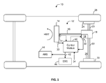
- the steering system 12 includes a handwheel 14 coupled to a steering shaft system 16 which includes steering column, intermediate shaft, & the necessary joints.
- the steering system 12 is an electric power steering (EPS) system that further includes a steering assist unit 18 that couples to the steering shaft system 16 of the steering system 12 and to tie rods 20, 22 of the vehicle 10.
- EPS electric power steering
- steering assist unit 18 may be coupling the upper portion of the steering shaft system 16 with the lower portion of that system.
- the steering assist unit 18 includes, for example, a rack and pinion steering mechanism (not shown) that may be coupled through the steering shaft system 16 to a steering actuator motor 19 and gearing.
- a rack and pinion steering mechanism (not shown) that may be coupled through the steering shaft system 16 to a steering actuator motor 19 and gearing.
- the steering actuator motor 19 provides the assistance to move the tie rods 20, 22 which in turn moves steering knuckles 24, 26, respectively, coupled to roadway wheels 28, 30, respectively of the vehicle 10.
- the vehicle 10 further includes various sensors 31, 32, 33 that detect and measure observable conditions of the steering system 12 and/or of the vehicle 10.
- the sensors 31, 32, 33 generate sensor signals based on the observable conditions.
- the sensor 31 is a torque sensor that senses an input driver handwheel torque (HWT) applied to the handwheel 14 by the operator of the vehicle 10.
- the torque sensor generates a driver torque signal based thereon.
- the sensor 32 is a motor speed sensor that senses a rotational speed of the steering actuator motor 19.
- the sensor 32 generates a motor speed or velocity signal based thereon.
- the sensor 33 is a handwheel position sensor that senses a position of the handwheel 14.
- the sensor 33 generates a handwheel position signal based thereon.
- a control module 40 receives the one or more sensor signals input from sensors 31, 32, 33, and may receive other inputs, such as a vehicle speed signal 34.
- the control module 40 generates a command signal to control the steering actuator motor 19 of the steering system 12 based on one or more of the inputs and further based on the steering control systems and methods of the present disclosure.
- the steering control systems and methods of the present disclosure apply signal conditioning and perform friction classification to determine a surface friction level 42 as a control signal that can be used to control aspects of the steering system 12 through the steering assist unit 18.
- the surface friction level 42 can also be sent as an alert to an ABS 44 and/or ESC system 46 indicating a change in surface friction, which may be further classified as an on-center slip (i.e., at lower handwheel angle) or an off-center slip (i.e., at higher handwheel angle) as further described herein.
- Communication with the ABS 44, ESC system 46, and other systems can be performed using, for example, a controller area network (CAN) bus or other vehicle network known in the art to exchange signals such as the vehicle speed signal 34.
- CAN controller area network
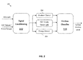
- FIG. 2 illustrates a schematic diagram of a control module 100 that represents a portion of the control logic within the control module 40 of FIG. 1 that detects a surface friction level using several EPS signals.
- the control module 100 includes a Signal Conditioning module 102, a Gradient Detect module 104, a Handwheel (HW) Steady Detect module 106, an Energy Detect module 108, and a Friction Classifier module 110.
- the Signal Conditioning module 102 can perform pre-processing of sensor data, such as a HW angle from sensor 33 and HW torque sensor data from sensor 31 to produce HWA, HWT and/or Pinion Torque, as well as derivative/delta values, and/or handwheel and vehicle speed.
- pinion torque can be derived by combining HWT and other internal EPS signals.
- Each of the modules 102-110 can be implemented as non-transitory executable instructions in memory of the control module 100 or formed in hardware and may be executed by one or more processing circuits of the control module 100.
- the outputs of the Gradient Detect module 104, the HW Steady Detect module 106, and the Energy Detect module 108 are used to estimate surface friction levels as will be described in more details further below by reference to FIGS. 7-10 .
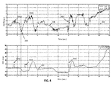
- FIG. 3 shows HWA data 202 (handwheel angle in degrees) and HWT data 204 (handwheel torque in Newton-meters) on a dry surface over a period of time. It is observed from FIG. 3 that for a linear increase in HWA, there is a corresponding increase in HWT on a dry surface. However, as shown in FIG. 4 , on a lower ⁇ (Mu) surface (i.e., a surface with a low coefficient of friction - e.g., an icy road), an increase in HWA does not correspond to a change in HWT because the friction is reduced. More specifically, FIG.
- HWA data 302 handwheel angle in degrees
- HWT data 304 handwheel torque in Newton-meters
- HWT The relationship between HWT and HWA when plotted for various road surface friction levels is shown by a graph illustrated in FIG. 5 . It is seen from this graph that the initial slope of HWT vs. HWA may be used to distinguish the road surfaces at lower handwheel angles.
- an initial slope value 406 may be calculated for a low mu value 402, e.g., an icy surface
- an initial slope value 408 may be calculated for a high mu value 404, e.g., dry pavement, at a HWA that is slightly above a minimum discernable angle 410.
- the minimum discernable angle 410 is the angle above which any surface friction may be estimated. That is, only beyond this angle the gradient values for various friction surfaces are different.
- the minimum discernable angle 410 is about 10 degrees and the initial slope values 406 and 408 are computed with respect to a change between the minimum discernable angle 410 and an offset 412 of about five degrees.
- the torque magnitude levels can also be used to distinguish the surfaces above a torque magnitude threshold 414, which is at about 50 degrees in the example of FIG. 5 .
- Torque (Tq) means either PT or HWT.
- the graph illustrated in FIG. 6 shows that multiple surface levels of friction may be differentiated based on varying T q level with HWA. For example, a surface with a low mu value, such as ice, has a lower slope than a mid-range mu value 504 of a snowy surface, and a higher mu value 506, such as dry pavement, has a higher slope.
- the mid-range mu value 504 can still be considered as a low surface friction condition relative to the higher mu value 506.
- a minimum discernable angle 510 can be defined as the angle above which any surface friction may be estimated for a PT vs. HWA relationship.
- FIG. 7 illustrates a schematic diagram of the Gradient Detect module 104 of FIG. 2 .
- the Gradient Detect module 104 may operate in two modes including one mode for lower handwheel angles (e.g., ⁇ 50 degrees) and another mode for higher handwheel angles (e.g., > 50 degrees).
- a region check 602 determines whether the handwheel position (i.e., handwheel angle) is on-center (ONC) for lower angles or off-center (OFC) for higher angles. If the region check 602 indicates that the absolute value of the handwheel angle (Abs_HWA) is OFC for higher angles, decision block 604 sets a gradient detect OFC indicator (GD_OFC).
- ONC on-center
- OFC off-center
- region check 602 indicates that the absolute value of the handwheel angle (Abs_HWA) is ONC for lower angles
- the decision block 604 sets an ONC indicator that is compared with gradient logic output 606 at an AND gate 608 to determine whether to set a gradient detect ONC indicator (GD_ONC).
- HWA-based Gradient table HWA(Degrees) Gradient (Newton Meter/Radian) 0 6 6 4.5 12 3.5 24 2 36 1 48 0 60 0 90 0 360 0
- This calibratable interpolated table Table 1
- the HWA-based gradient table can be a multi-variate table that interpolates based on multiple variables, such as HWA, vehicle speed, and handwheel speed.
- the Gradient Detect module 104 in the on-center (lower HWA) mode computes an HWA-dependent gradient value which is used as a reference to differentiate between friction levels.
- an instantaneous gradient value 610 is calculated and compared with the output from the interpolated table (Table 1) at gradient check condition 612. If the instantaneous gradient value 610 is less than the upper limit table values generated by gradient calculation 615 and more than lower limit table values generated by gradient calcutation 615 in gradient check condition 612, then decision block 614 sets the gradient logic output 606 and the on-center gradient detect signal (GD_ONC) is triggered.
- the return check 618 checks if the handwheel 14 is moving toward or away from the center based on the absolute value of HWA (Abs_HWA). This check ensures that Gradient Detect module 104 is active only when the driver is taking a turn or the handwheel 14 is moving away from the center.
- the threshold check 616 checks ⁇ HWT and ⁇ HWA signals (i.e., absolute value of a change in HWT (Abs_dHWT) and absolute value of a change in HWA (Abs_dHWA), respectively) to see if they are above a certain threshold.
- the Gradient Detect module 104 of an embodiment is active only if both ⁇ HWT and ⁇ HWA signals are above a certain threshold (i.e., a threshold value).
- a threshold value i.e., a threshold value.
- the threshold for ⁇ HWT is used to eliminate noise while the threshold for ⁇ HWA is used to ignore negligible deviations in steering maneuvers.
- the output of the threshold check 616 and return check 618 are passed to an AND gate 620 followed by a decision block 622 leading to the region check 602 when both the threshold check 616 and the return check 618 are satisfied.
- on-center gradient detection conditions ⁇ Tq ⁇ HWA slippery ⁇ ⁇ Tq ⁇ HWA dry
- ⁇ ⁇ Tq ⁇ HWA dry Ideal G d ⁇ Tq ⁇ HWA slippery ⁇ G d ⁇ Tq slippery ⁇ G d * ⁇ HWA slippery This is lower-limited by a noise threshold.
- the on-center gradient detect is triggered when both conditions (1) and (2) are satisfied and the steering is moving away from center.
- the off-center gradient detect of an embodiment just checks for ⁇ HWT and ⁇ HWA thresholds and whether the steering is returning to the center or not according to the following conditions: Noise Threshold ⁇ ⁇ Tq slippery Small Deviation ⁇ ⁇ HWA slippery The off-center gradient detect is triggered when both conditions (3) and (4) are satisfied and the steering is moving away from center.
- FIG. 8 illustrates a schematic diagram of the Energy Detect module 108 shown in FIG. 2 .
- the amount of energy that the Electric Power Steering (EPS) system expends while steering the handwheel 14 is used as an estimate of the surface friction.
- the graphs illustrated in FIGS. 5 and 6 show that, at higher handwheel angles, gradient values may not be used as a measure to detect changes in friction levels as T q saturates with T q and the gradient values become very small.
- the absolute value of T q is used to differentiate between friction levels at higher handwheel angles.
- an energy value is an absolute measure and may be used for this purpose.
- an energy value as well as a gradient value may be used for detection purposes. Using both values adds robustness to the embodiments of the invention by reducing false detects.
- HWA-based energy table HWA(Degrees) Energy (Joules) 10 0.4 18 0.9 24 1.2 36 1.8 40 2.3 50 2.5 60 3 70 3.8 80 4.4 90 4.7 100 5.23 360 18.8496
- This calibratable interpolated table (Table 2) has the lowest possible energy at a particular HWA obtained by testing on a high friction surface.
- the HWA-based energy table can be a multi-variate table that interpolates based on multiple variables, such as HWA, vehicle speed, and handwheel speed.
- the Energy Detect module 108 computes a HWA-dependent energy, which is used as a reference to differentiate between friction levels. The instantaneous energy is calculated and compared with the output from the interpolated table (Table 2) at energy check 702 vs. an energy limit computed by an energy limit calculation 704 based on a sign of the change in HWA (Sgn_dHWA) and an absolute value of the HWA (Abs_HWA). If the instantaneous energy is lesser than the table values, then the energy detect on-center signal (ED_ONC) is triggered. Hence, energy detect is triggered when the condition (5) below is satisfied: Tq * HWA slippery ⁇ Tq * HWA dry nominal
- the region check 712 shown in FIG. 8 is used to determine whether the handwheel position is on-center (e.g., Abs_HWA ⁇ 50 degrees) or off-center (e.g., Abs_HWA > 50 degrees). Based on the determination, the corresponding detect is triggered through decision block 714. If the decision block 714 determines that HWA is OFC based on region check 712 and the instantaneous energy is below the energy limit as determined by energy check 702 and decision block 706, as gated by AND-gate 710, the energy detect off-center signal (ED_OFC) is set. Similarly, if the decision block 714 determines that HWA is ONC in combination with determining that the energy limit as determined by energy check 702 and decision block 706 is below the limit, then AND-gate 708 delivers the energy detect ONC signal.
- ED_OFC energy detect off-center signal
- FIG. 9 illustrates a schematic diagram of the HW Steady Detect module 106 shown in FIG. 2 .
- the HW Steady Detect module 106 detects the steadiness of handwheel 14 of FIG. 1 using HW steady determination 802 that monitors the absolute value of the change in HWA (Abs_dHWA), vehicle speed, a feedback from HW_Steady_Global. Most of the steering maneuvers start by going straight and then taking a turn. In some cases, when the handwheel 14 is at an angle, the driver further turns it away from the center.
- the control module 100 detects a change of friction for such steering maneuvers.
- control module 100 would not detect the lower friction levels when the driver is turning the handwheel 14 back towards the center or in a back-and-forth motion.
- the HW Steady Detect module 106 is focused on capturing these maneuvering conditions in order to determine when the control module 100 is to detect a change of friction.
- the global handwheel steady signal (HW_Steady_Global) is triggered when the vehicle 10 moves for a certain distance (i.e., an enough distance to perform calibration) such that the HWA varies less than a certain amount at each sampling instance in time.
- the HW Steady Detect module 106 shown in FIG. 9 generates the global handwheel steady signal (HW_Steady_Global).
- the HW Steady Detect 106 module is also configured to detect repeated back-and-forth maneuvers on the handwheel 14 to avoid false detection.
- the HW Steady Detect module 106 makes the detection algorithm more robust.
- HW Steady Detect module 106 shown in FIG. 9 records the angle at which the handwheel 14 becomes steady.
- HW steady angle 804 determines a handwheel steady angle (HW_Steady_angle) based on a sign of the change in HWA (Sgn_dHWA), a sign of HWA (Sgn_HWA), and the global handwheel steady signal (HW_Steady_Global).
- This angle is then used to classify the steering position as on-center 808 or off-center 810 with respect to the global handwheel steady signal (HW_Steady_Global), and the corresponding HW Steady signal (HW_Steady_ONC or HW_Steady_OFC) is set based on the classification by region check 806.
- FIG. 10 illustrates a schematic diagram of the Friction Classifier module 110 shown in FIG. 2 .
- a slip i.e., a reduction in the surface friction detect is triggered when all the three signals, namely, Gradient Detect, Energy Detect and handwheel Steady, are high simultaneously. If the three signals are on-center (GD_ONC, HW_Steady_ONC, and ED ONC) at AND-gate 902, the slip is classified as an on-center slip (Slip ONC). If the three signals are off-center (GD_OFC, HW_Steady_OFC, and ED OFC) at AND-gate 902, then the slip is classified as an off-center slip (Slip OFC).
Applications Claiming Priority (1)
| Application Number | Priority Date | Filing Date | Title |
|---|---|---|---|
| US201462016393P | 2014-06-24 | 2014-06-24 |
Publications (2)
| Publication Number | Publication Date |
|---|---|
| EP2960137A1 true EP2960137A1 (de) | 2015-12-30 |
| EP2960137B1 EP2960137B1 (de) | 2017-08-30 |
Family
ID=53489854
Family Applications (1)
| Application Number | Title | Priority Date | Filing Date |
|---|---|---|---|
| EP15173204.7A Active EP2960137B1 (de) | 2014-06-24 | 2015-06-22 | Erfassung einer veränderung der oberflächenreibung mittels elektrischer servolenkungssignale |
Country Status (3)
| Country | Link |
|---|---|
| US (1) | US9550523B2 (de) |
| EP (1) | EP2960137B1 (de) |
| CN (1) | CN105197015B (de) |
Cited By (3)
| Publication number | Priority date | Publication date | Assignee | Title |
|---|---|---|---|---|
| WO2020056403A1 (en) * | 2018-09-14 | 2020-03-19 | Uatc, Llc | Driving surface friction estimations for vehicles |
| US11427223B2 (en) | 2018-09-14 | 2022-08-30 | Uatc, Llc | Driving surface friction estimations for autonomous vehicles |
| US11465630B2 (en) | 2018-09-14 | 2022-10-11 | Uatc, Llc | Driving surface friction estimations using vehicle steering |
Families Citing this family (9)
| Publication number | Priority date | Publication date | Assignee | Title |
|---|---|---|---|---|
| US10399597B2 (en) | 2015-10-09 | 2019-09-03 | Steering Solutions Ip Holding Corporation | Payload estimation using electric power steering signals |
| DE102017103034B4 (de) | 2016-02-16 | 2022-02-10 | Steering Solutions Ip Holding Corporation | Lenkungssystem zum Detektieren von Bewegungszuständen eines Fahrzeugs |
| US10800443B2 (en) | 2017-09-21 | 2020-10-13 | Steering Solutions Ip Holding Corporation | Catch motor torque generation in steer by wire system |
| US11377140B2 (en) | 2017-12-07 | 2022-07-05 | Steering Solutions Ip Holding Corporation | Notification for rack limiting conditions for steer by wire steering systems |
| US10906581B2 (en) | 2017-12-07 | 2021-02-02 | Steering Solutions Ip Holding Corporation | Rack-limiting condition detection and the corresponding steering wheel torque feedback for steer by wire steering systems |
| US11110956B2 (en) | 2018-02-22 | 2021-09-07 | Steering Solutions Ip Holding Corporation | Quadrant based friction compensation for tire load estimation in steering systems |
| US11498613B2 (en) * | 2019-02-14 | 2022-11-15 | Steering Solutions Ip Holding Corporation | Road friction coefficient estimation using steering system signals |
| US11511790B2 (en) * | 2019-02-14 | 2022-11-29 | Steering Solutions Ip Holding Corporation | Road friction coefficient estimation using steering system signals |
| US11834108B2 (en) | 2020-11-30 | 2023-12-05 | Steering Solutions Ip Holding Corporation | Dynamic vehicle model based assist without torque sensor |
Citations (3)
| Publication number | Priority date | Publication date | Assignee | Title |
|---|---|---|---|---|
| EP1275937A2 (de) * | 2001-07-12 | 2003-01-15 | Kabushiki Kaisha Toyota Chuo Kenkyusho | Schätzvorrichtung für eine physikalische Grösse; Schätzvorrichtung für den Strassenoberflächenreibwert, für den Lenkwinkelneutralwert und die Luftdruckverminderung |
| EP1640246A2 (de) * | 2004-09-27 | 2006-03-29 | Nissan Motor Company, Limited | Lenkungs-Steuerungseinrichtung für Fahrzeug |
| EP2177421A2 (de) * | 2008-10-20 | 2010-04-21 | GM Global Technology Operations, Inc. | Servolenkung |
Family Cites Families (21)
| Publication number | Priority date | Publication date | Assignee | Title |
|---|---|---|---|---|
| US5828973A (en) * | 1995-03-17 | 1998-10-27 | Nippondenso Co., Ltd. | Electric power steering apparatus |
| JP3951205B2 (ja) * | 1998-05-19 | 2007-08-01 | 株式会社デンソー | パワーステアリング方法およびパワーステアリング装置 |
| GB9919277D0 (en) * | 1999-08-17 | 1999-10-20 | Trw Lucas Varity Electric | Method and apparatus for controlling an electric power assisted steering system using an adaptive blending torque filter |
| EP1357007B1 (de) * | 2002-04-23 | 2006-05-17 | Aisin Seiki Kabushiki Kaisha | Vorrichtung zur Schätzung des Haftungsfaktors eines Fahrzeugrades |
| JP4353058B2 (ja) * | 2004-10-12 | 2009-10-28 | トヨタ自動車株式会社 | 電動式パワーステアリング装置用制御装置 |
| EP1837266B1 (de) * | 2005-01-14 | 2012-03-14 | Nsk Ltd. | Kontrollgerät für eine elektrische servolenkung |
| JP4314489B2 (ja) * | 2005-09-16 | 2009-08-19 | トヨタ自動車株式会社 | 車両の操舵装置 |
| JP4872298B2 (ja) * | 2005-10-04 | 2012-02-08 | 日本精工株式会社 | 電動パワーステアリング装置の制御装置 |
| JP5109342B2 (ja) * | 2006-11-15 | 2012-12-26 | 日本精工株式会社 | 電動パワーステアリング装置 |
| US20080294313A1 (en) * | 2007-05-25 | 2008-11-27 | Nsk Ltd. | Electric power steering apparatus |
| EP2275323B1 (de) * | 2008-05-16 | 2013-04-17 | Honda Motor Co., Ltd. | Elektrische servolenkvorrichtung |
| JP5035419B2 (ja) * | 2008-06-30 | 2012-09-26 | 日産自動車株式会社 | 路面摩擦係数推定装置及び路面摩擦係数推定方法 |
| KR100963967B1 (ko) * | 2008-11-19 | 2010-06-15 | 현대모비스 주식회사 | 전동식 파워스티어링 시스템의 조향 보상방법 |
| DE102009048092A1 (de) * | 2009-10-02 | 2011-04-07 | Thyssenkrupp Presta Ag | Sicherheitseinrichtung für elektrische Servolenkung |
| GB201006290D0 (en) * | 2010-04-15 | 2010-06-02 | Trw Ltd | Electric power steering system |
| JP5093295B2 (ja) * | 2010-05-24 | 2012-12-12 | トヨタ自動車株式会社 | 操舵装置及び操舵制御装置 |
| JP5429142B2 (ja) * | 2010-11-18 | 2014-02-26 | 日本精工株式会社 | 電動パワーステアリング装置 |
| CN103237707B (zh) * | 2010-12-01 | 2015-05-06 | 丰田自动车株式会社 | 车辆的运动控制装置 |
| JP5827059B2 (ja) * | 2011-08-01 | 2015-12-02 | 株式会社ジェイテクト | 路面摩擦係数推定装置、駆動力配分制御装置、及び四輪駆動車 |
| CN102529976B (zh) * | 2011-12-15 | 2014-04-16 | 东南大学 | 一种基于滑模观测器的车辆运行状态非线性鲁棒估计方法 |
| KR20140145528A (ko) * | 2012-04-18 | 2014-12-23 | 이턴 코포레이션 | 도로면 마찰계수의 실시간 추정 방법 및 장치 |
-
2015
- 2015-06-22 US US14/746,041 patent/US9550523B2/en active Active
- 2015-06-22 EP EP15173204.7A patent/EP2960137B1/de active Active
- 2015-06-24 CN CN201510470299.1A patent/CN105197015B/zh active Active
Patent Citations (3)
| Publication number | Priority date | Publication date | Assignee | Title |
|---|---|---|---|---|
| EP1275937A2 (de) * | 2001-07-12 | 2003-01-15 | Kabushiki Kaisha Toyota Chuo Kenkyusho | Schätzvorrichtung für eine physikalische Grösse; Schätzvorrichtung für den Strassenoberflächenreibwert, für den Lenkwinkelneutralwert und die Luftdruckverminderung |
| EP1640246A2 (de) * | 2004-09-27 | 2006-03-29 | Nissan Motor Company, Limited | Lenkungs-Steuerungseinrichtung für Fahrzeug |
| EP2177421A2 (de) * | 2008-10-20 | 2010-04-21 | GM Global Technology Operations, Inc. | Servolenkung |
Cited By (4)
| Publication number | Priority date | Publication date | Assignee | Title |
|---|---|---|---|---|
| WO2020056403A1 (en) * | 2018-09-14 | 2020-03-19 | Uatc, Llc | Driving surface friction estimations for vehicles |
| US11427223B2 (en) | 2018-09-14 | 2022-08-30 | Uatc, Llc | Driving surface friction estimations for autonomous vehicles |
| US11465630B2 (en) | 2018-09-14 | 2022-10-11 | Uatc, Llc | Driving surface friction estimations using vehicle steering |
| US11919499B2 (en) | 2018-09-14 | 2024-03-05 | Uatc, Llc | Driving surface friction estimations using vehicle steering |
Also Published As
| Publication number | Publication date |
|---|---|
| EP2960137B1 (de) | 2017-08-30 |
| CN105197015B (zh) | 2018-11-02 |
| US9550523B2 (en) | 2017-01-24 |
| US20150367884A1 (en) | 2015-12-24 |
| CN105197015A (zh) | 2015-12-30 |
Similar Documents
| Publication | Publication Date | Title |
|---|---|---|
| EP2960137B1 (de) | Erfassung einer veränderung der oberflächenreibung mittels elektrischer servolenkungssignale | |
| US10155534B2 (en) | Driver intent estimation without using torque sensor signal | |
| US9845109B2 (en) | Continuous estimation of surface friction coefficient based on EPS and vehicle models | |
| EP3006306B1 (de) | Bereitstellung von unterstützungsdrehmoment ohne handraddrehmomentsensor für null- bis niedrige fahrzeugdrehzahlen | |
| US10378890B2 (en) | Apparatus and method for determining wheel alignment change of vehicle | |
| US9168921B2 (en) | Method for warning a driver of a motor vehicle of an obstacle present in a side area next to a side flank of the vehicle and motor vehicle with a driver assistance system | |
| EP2799310B1 (de) | Bereitstellung von Unterstützungsdrehmoment ohne Handraddrehmomentsensor | |
| EP2999614B1 (de) | Steuerung einer hinterradlenkung | |
| US9469343B2 (en) | System, method, and computer-readable recording medium for lane keeping control | |
| US9150244B2 (en) | Friction estimation and detection for an electric power steering system | |
| US11511790B2 (en) | Road friction coefficient estimation using steering system signals | |
| EP2778020A2 (de) | Störungsunterdrückung basierend auf Lenkradbeschleunigung | |
| US9037351B2 (en) | Steering control device | |
| EP1760451A1 (de) | Vorrichtung und Verfahren zur Bestimmung des Reibwerts einer Strassenoberfläche | |
| US10538269B2 (en) | Steering system handwheel angle determination | |
| WO2003099635A1 (fr) | Dispositif de direction | |
| EP2873590B1 (de) | Handradwinkel aus dynamischen Sensoren oder Raddrehzahlen eines Fahrzeugs | |
| US20170072996A1 (en) | Apparatus and method for controlling electric power steering system | |
| JP5331074B2 (ja) | ステアリング装置 | |
| CN111572548B (zh) | 使用转向系统信号的道路摩擦系数估计 | |
| KR20230023080A (ko) | 자율 주행을 위한 전동식 조향장치 및 그 방법 | |
| RU2702878C1 (ru) | Способ предотвращения сноса и заноса колес автомобиля | |
| JP5025686B2 (ja) | 車両挙動制御装置 | |
| JP2010064682A (ja) | 車両用操舵制御装置 | |
| WO2009157473A1 (ja) | 運転者状態推定装置 |
Legal Events
| Date | Code | Title | Description |
|---|---|---|---|
| PUAI | Public reference made under article 153(3) epc to a published international application that has entered the european phase |
Free format text: ORIGINAL CODE: 0009012 |
|
| AK | Designated contracting states |
Kind code of ref document: A1 Designated state(s): AL AT BE BG CH CY CZ DE DK EE ES FI FR GB GR HR HU IE IS IT LI LT LU LV MC MK MT NL NO PL PT RO RS SE SI SK SM TR |
|
| AX | Request for extension of the european patent |
Extension state: BA ME |
|
| 17P | Request for examination filed |
Effective date: 20160628 |
|
| RBV | Designated contracting states (corrected) |
Designated state(s): AL AT BE BG CH CY CZ DE DK EE ES FI FR GB GR HR HU IE IS IT LI LT LU LV MC MK MT NL NO PL PT RO RS SE SI SK SM TR |
|
| GRAP | Despatch of communication of intention to grant a patent |
Free format text: ORIGINAL CODE: EPIDOSNIGR1 |
|
| RIC1 | Information provided on ipc code assigned before grant |
Ipc: B60W 10/18 20120101ALI20170216BHEP Ipc: B62D 6/00 20060101ALI20170216BHEP Ipc: B62D 5/04 20060101AFI20170216BHEP Ipc: B62D 6/04 20060101ALI20170216BHEP Ipc: B60W 10/20 20060101ALI20170216BHEP Ipc: B62D 6/10 20060101ALI20170216BHEP Ipc: B60W 40/068 20120101ALI20170216BHEP Ipc: B60W 30/02 20120101ALI20170216BHEP |
|
| INTG | Intention to grant announced |
Effective date: 20170309 |
|
| GRAS | Grant fee paid |
Free format text: ORIGINAL CODE: EPIDOSNIGR3 |
|
| GRAA | (expected) grant |
Free format text: ORIGINAL CODE: 0009210 |
|
| AK | Designated contracting states |
Kind code of ref document: B1 Designated state(s): AL AT BE BG CH CY CZ DE DK EE ES FI FR GB GR HR HU IE IS IT LI LT LU LV MC MK MT NL NO PL PT RO RS SE SI SK SM TR |
|
| REG | Reference to a national code |
Ref country code: GB Ref legal event code: FG4D |
|
| REG | Reference to a national code |
Ref country code: CH Ref legal event code: EP |
|
| REG | Reference to a national code |
Ref country code: AT Ref legal event code: REF Ref document number: 923232 Country of ref document: AT Kind code of ref document: T Effective date: 20170915 |
|
| REG | Reference to a national code |
Ref country code: IE Ref legal event code: FG4D |
|
| REG | Reference to a national code |
Ref country code: DE Ref legal event code: R096 Ref document number: 602015004394 Country of ref document: DE |
|
| REG | Reference to a national code |
Ref country code: NL Ref legal event code: MP Effective date: 20170830 |
|
| REG | Reference to a national code |
Ref country code: LT Ref legal event code: MG4D |
|
| REG | Reference to a national code |
Ref country code: AT Ref legal event code: MK05 Ref document number: 923232 Country of ref document: AT Kind code of ref document: T Effective date: 20170830 |
|
| PG25 | Lapsed in a contracting state [announced via postgrant information from national office to epo] |
Ref country code: AT Free format text: LAPSE BECAUSE OF FAILURE TO SUBMIT A TRANSLATION OF THE DESCRIPTION OR TO PAY THE FEE WITHIN THE PRESCRIBED TIME-LIMIT Effective date: 20170830 Ref country code: SE Free format text: LAPSE BECAUSE OF FAILURE TO SUBMIT A TRANSLATION OF THE DESCRIPTION OR TO PAY THE FEE WITHIN THE PRESCRIBED TIME-LIMIT Effective date: 20170830 Ref country code: NO Free format text: LAPSE BECAUSE OF FAILURE TO SUBMIT A TRANSLATION OF THE DESCRIPTION OR TO PAY THE FEE WITHIN THE PRESCRIBED TIME-LIMIT Effective date: 20171130 Ref country code: HR Free format text: LAPSE BECAUSE OF FAILURE TO SUBMIT A TRANSLATION OF THE DESCRIPTION OR TO PAY THE FEE WITHIN THE PRESCRIBED TIME-LIMIT Effective date: 20170830 Ref country code: LT Free format text: LAPSE BECAUSE OF FAILURE TO SUBMIT A TRANSLATION OF THE DESCRIPTION OR TO PAY THE FEE WITHIN THE PRESCRIBED TIME-LIMIT Effective date: 20170830 Ref country code: FI Free format text: LAPSE BECAUSE OF FAILURE TO SUBMIT A TRANSLATION OF THE DESCRIPTION OR TO PAY THE FEE WITHIN THE PRESCRIBED TIME-LIMIT Effective date: 20170830 |
|
| PG25 | Lapsed in a contracting state [announced via postgrant information from national office to epo] |
Ref country code: GR Free format text: LAPSE BECAUSE OF FAILURE TO SUBMIT A TRANSLATION OF THE DESCRIPTION OR TO PAY THE FEE WITHIN THE PRESCRIBED TIME-LIMIT Effective date: 20171201 Ref country code: ES Free format text: LAPSE BECAUSE OF FAILURE TO SUBMIT A TRANSLATION OF THE DESCRIPTION OR TO PAY THE FEE WITHIN THE PRESCRIBED TIME-LIMIT Effective date: 20170830 Ref country code: BG Free format text: LAPSE BECAUSE OF FAILURE TO SUBMIT A TRANSLATION OF THE DESCRIPTION OR TO PAY THE FEE WITHIN THE PRESCRIBED TIME-LIMIT Effective date: 20171130 Ref country code: RS Free format text: LAPSE BECAUSE OF FAILURE TO SUBMIT A TRANSLATION OF THE DESCRIPTION OR TO PAY THE FEE WITHIN THE PRESCRIBED TIME-LIMIT Effective date: 20170830 Ref country code: IS Free format text: LAPSE BECAUSE OF FAILURE TO SUBMIT A TRANSLATION OF THE DESCRIPTION OR TO PAY THE FEE WITHIN THE PRESCRIBED TIME-LIMIT Effective date: 20171230 Ref country code: LV Free format text: LAPSE BECAUSE OF FAILURE TO SUBMIT A TRANSLATION OF THE DESCRIPTION OR TO PAY THE FEE WITHIN THE PRESCRIBED TIME-LIMIT Effective date: 20170830 |
|
| PG25 | Lapsed in a contracting state [announced via postgrant information from national office to epo] |
Ref country code: NL Free format text: LAPSE BECAUSE OF FAILURE TO SUBMIT A TRANSLATION OF THE DESCRIPTION OR TO PAY THE FEE WITHIN THE PRESCRIBED TIME-LIMIT Effective date: 20170830 |
|
| PG25 | Lapsed in a contracting state [announced via postgrant information from national office to epo] |
Ref country code: PL Free format text: LAPSE BECAUSE OF FAILURE TO SUBMIT A TRANSLATION OF THE DESCRIPTION OR TO PAY THE FEE WITHIN THE PRESCRIBED TIME-LIMIT Effective date: 20170830 Ref country code: DK Free format text: LAPSE BECAUSE OF FAILURE TO SUBMIT A TRANSLATION OF THE DESCRIPTION OR TO PAY THE FEE WITHIN THE PRESCRIBED TIME-LIMIT Effective date: 20170830 Ref country code: RO Free format text: LAPSE BECAUSE OF FAILURE TO SUBMIT A TRANSLATION OF THE DESCRIPTION OR TO PAY THE FEE WITHIN THE PRESCRIBED TIME-LIMIT Effective date: 20170830 Ref country code: CZ Free format text: LAPSE BECAUSE OF FAILURE TO SUBMIT A TRANSLATION OF THE DESCRIPTION OR TO PAY THE FEE WITHIN THE PRESCRIBED TIME-LIMIT Effective date: 20170830 |
|
| PG25 | Lapsed in a contracting state [announced via postgrant information from national office to epo] |
Ref country code: SM Free format text: LAPSE BECAUSE OF FAILURE TO SUBMIT A TRANSLATION OF THE DESCRIPTION OR TO PAY THE FEE WITHIN THE PRESCRIBED TIME-LIMIT Effective date: 20170830 Ref country code: IT Free format text: LAPSE BECAUSE OF FAILURE TO SUBMIT A TRANSLATION OF THE DESCRIPTION OR TO PAY THE FEE WITHIN THE PRESCRIBED TIME-LIMIT Effective date: 20170830 Ref country code: SK Free format text: LAPSE BECAUSE OF FAILURE TO SUBMIT A TRANSLATION OF THE DESCRIPTION OR TO PAY THE FEE WITHIN THE PRESCRIBED TIME-LIMIT Effective date: 20170830 Ref country code: EE Free format text: LAPSE BECAUSE OF FAILURE TO SUBMIT A TRANSLATION OF THE DESCRIPTION OR TO PAY THE FEE WITHIN THE PRESCRIBED TIME-LIMIT Effective date: 20170830 |
|
| REG | Reference to a national code |
Ref country code: DE Ref legal event code: R097 Ref document number: 602015004394 Country of ref document: DE |
|
| PLBE | No opposition filed within time limit |
Free format text: ORIGINAL CODE: 0009261 |
|
| STAA | Information on the status of an ep patent application or granted ep patent |
Free format text: STATUS: NO OPPOSITION FILED WITHIN TIME LIMIT |
|
| 26N | No opposition filed |
Effective date: 20180531 |
|
| PG25 | Lapsed in a contracting state [announced via postgrant information from national office to epo] |
Ref country code: SI Free format text: LAPSE BECAUSE OF FAILURE TO SUBMIT A TRANSLATION OF THE DESCRIPTION OR TO PAY THE FEE WITHIN THE PRESCRIBED TIME-LIMIT Effective date: 20170830 |
|
| REG | Reference to a national code |
Ref country code: CH Ref legal event code: PL |
|
| REG | Reference to a national code |
Ref country code: BE Ref legal event code: MM Effective date: 20180630 |
|
| REG | Reference to a national code |
Ref country code: IE Ref legal event code: MM4A |
|
| PG25 | Lapsed in a contracting state [announced via postgrant information from national office to epo] |
Ref country code: LU Free format text: LAPSE BECAUSE OF NON-PAYMENT OF DUE FEES Effective date: 20180622 Ref country code: MC Free format text: LAPSE BECAUSE OF FAILURE TO SUBMIT A TRANSLATION OF THE DESCRIPTION OR TO PAY THE FEE WITHIN THE PRESCRIBED TIME-LIMIT Effective date: 20170830 |
|
| PG25 | Lapsed in a contracting state [announced via postgrant information from national office to epo] |
Ref country code: FR Free format text: LAPSE BECAUSE OF NON-PAYMENT OF DUE FEES Effective date: 20180630 Ref country code: CH Free format text: LAPSE BECAUSE OF NON-PAYMENT OF DUE FEES Effective date: 20180630 Ref country code: LI Free format text: LAPSE BECAUSE OF NON-PAYMENT OF DUE FEES Effective date: 20180630 Ref country code: IE Free format text: LAPSE BECAUSE OF NON-PAYMENT OF DUE FEES Effective date: 20180622 |
|
| PG25 | Lapsed in a contracting state [announced via postgrant information from national office to epo] |
Ref country code: BE Free format text: LAPSE BECAUSE OF NON-PAYMENT OF DUE FEES Effective date: 20180630 |
|
| PG25 | Lapsed in a contracting state [announced via postgrant information from national office to epo] |
Ref country code: MT Free format text: LAPSE BECAUSE OF NON-PAYMENT OF DUE FEES Effective date: 20180622 |
|
| GBPC | Gb: european patent ceased through non-payment of renewal fee |
Effective date: 20190622 |
|
| PG25 | Lapsed in a contracting state [announced via postgrant information from national office to epo] |
Ref country code: TR Free format text: LAPSE BECAUSE OF FAILURE TO SUBMIT A TRANSLATION OF THE DESCRIPTION OR TO PAY THE FEE WITHIN THE PRESCRIBED TIME-LIMIT Effective date: 20170830 |
|
| PG25 | Lapsed in a contracting state [announced via postgrant information from national office to epo] |
Ref country code: GB Free format text: LAPSE BECAUSE OF NON-PAYMENT OF DUE FEES Effective date: 20190622 |
|
| PG25 | Lapsed in a contracting state [announced via postgrant information from national office to epo] |
Ref country code: PT Free format text: LAPSE BECAUSE OF FAILURE TO SUBMIT A TRANSLATION OF THE DESCRIPTION OR TO PAY THE FEE WITHIN THE PRESCRIBED TIME-LIMIT Effective date: 20170830 |
|
| PG25 | Lapsed in a contracting state [announced via postgrant information from national office to epo] |
Ref country code: HU Free format text: LAPSE BECAUSE OF FAILURE TO SUBMIT A TRANSLATION OF THE DESCRIPTION OR TO PAY THE FEE WITHIN THE PRESCRIBED TIME-LIMIT; INVALID AB INITIO Effective date: 20150622 Ref country code: MK Free format text: LAPSE BECAUSE OF NON-PAYMENT OF DUE FEES Effective date: 20170830 Ref country code: CY Free format text: LAPSE BECAUSE OF FAILURE TO SUBMIT A TRANSLATION OF THE DESCRIPTION OR TO PAY THE FEE WITHIN THE PRESCRIBED TIME-LIMIT Effective date: 20170830 |
|
| PG25 | Lapsed in a contracting state [announced via postgrant information from national office to epo] |
Ref country code: AL Free format text: LAPSE BECAUSE OF FAILURE TO SUBMIT A TRANSLATION OF THE DESCRIPTION OR TO PAY THE FEE WITHIN THE PRESCRIBED TIME-LIMIT Effective date: 20170830 |
|
| PGFP | Annual fee paid to national office [announced via postgrant information from national office to epo] |
Ref country code: DE Payment date: 20230626 Year of fee payment: 9 |