EP2959964A1 - Verfahren zum betreiben einer umkehrosmose-membranvorrichtung - Google Patents
Verfahren zum betreiben einer umkehrosmose-membranvorrichtung Download PDFInfo
- Publication number
- EP2959964A1 EP2959964A1 EP14754337.5A EP14754337A EP2959964A1 EP 2959964 A1 EP2959964 A1 EP 2959964A1 EP 14754337 A EP14754337 A EP 14754337A EP 2959964 A1 EP2959964 A1 EP 2959964A1
- Authority
- EP
- European Patent Office
- Prior art keywords
- reverse osmosis
- osmosis membrane
- water
- flow rate
- permeate water
- Prior art date
- Legal status (The legal status is an assumption and is not a legal conclusion. Google has not performed a legal analysis and makes no representation as to the accuracy of the status listed.)
- Withdrawn
Links
Images


Classifications
-
- C—CHEMISTRY; METALLURGY
- C02—TREATMENT OF WATER, WASTE WATER, SEWAGE, OR SLUDGE
- C02F—TREATMENT OF WATER, WASTE WATER, SEWAGE, OR SLUDGE
- C02F1/00—Treatment of water, waste water, or sewage
- C02F1/44—Treatment of water, waste water, or sewage by dialysis, osmosis or reverse osmosis
- C02F1/441—Treatment of water, waste water, or sewage by dialysis, osmosis or reverse osmosis by reverse osmosis
-
- B—PERFORMING OPERATIONS; TRANSPORTING
- B01—PHYSICAL OR CHEMICAL PROCESSES OR APPARATUS IN GENERAL
- B01D—SEPARATION
- B01D61/00—Processes of separation using semi-permeable membranes, e.g. dialysis, osmosis or ultrafiltration; Apparatus, accessories or auxiliary operations specially adapted therefor
- B01D61/02—Reverse osmosis; Hyperfiltration ; Nanofiltration
- B01D61/025—Reverse osmosis; Hyperfiltration
-
- B—PERFORMING OPERATIONS; TRANSPORTING
- B01—PHYSICAL OR CHEMICAL PROCESSES OR APPARATUS IN GENERAL
- B01D—SEPARATION
- B01D61/00—Processes of separation using semi-permeable membranes, e.g. dialysis, osmosis or ultrafiltration; Apparatus, accessories or auxiliary operations specially adapted therefor
- B01D61/02—Reverse osmosis; Hyperfiltration ; Nanofiltration
- B01D61/12—Controlling or regulating
-
- B—PERFORMING OPERATIONS; TRANSPORTING
- B01—PHYSICAL OR CHEMICAL PROCESSES OR APPARATUS IN GENERAL
- B01D—SEPARATION
- B01D2311/00—Details relating to membrane separation process operations and control
- B01D2311/10—Temperature control
-
- B—PERFORMING OPERATIONS; TRANSPORTING
- B01—PHYSICAL OR CHEMICAL PROCESSES OR APPARATUS IN GENERAL
- B01D—SEPARATION
- B01D2311/00—Details relating to membrane separation process operations and control
- B01D2311/16—Flow or flux control
-
- B—PERFORMING OPERATIONS; TRANSPORTING
- B01—PHYSICAL OR CHEMICAL PROCESSES OR APPARATUS IN GENERAL
- B01D—SEPARATION
- B01D2311/00—Details relating to membrane separation process operations and control
- B01D2311/24—Quality control
- B01D2311/246—Concentration control
-
- B—PERFORMING OPERATIONS; TRANSPORTING
- B01—PHYSICAL OR CHEMICAL PROCESSES OR APPARATUS IN GENERAL
- B01D—SEPARATION
- B01D2313/00—Details relating to membrane modules or apparatus
- B01D2313/24—Specific pressurizing or depressurizing means
- B01D2313/243—Pumps
-
- C—CHEMISTRY; METALLURGY
- C02—TREATMENT OF WATER, WASTE WATER, SEWAGE, OR SLUDGE
- C02F—TREATMENT OF WATER, WASTE WATER, SEWAGE, OR SLUDGE
- C02F2103/00—Nature of the water, waste water, sewage or sludge to be treated
- C02F2103/08—Seawater, e.g. for desalination
-
- Y—GENERAL TAGGING OF NEW TECHNOLOGICAL DEVELOPMENTS; GENERAL TAGGING OF CROSS-SECTIONAL TECHNOLOGIES SPANNING OVER SEVERAL SECTIONS OF THE IPC; TECHNICAL SUBJECTS COVERED BY FORMER USPC CROSS-REFERENCE ART COLLECTIONS [XRACs] AND DIGESTS
- Y02—TECHNOLOGIES OR APPLICATIONS FOR MITIGATION OR ADAPTATION AGAINST CLIMATE CHANGE
- Y02A—TECHNOLOGIES FOR ADAPTATION TO CLIMATE CHANGE
- Y02A20/00—Water conservation; Efficient water supply; Efficient water use
- Y02A20/124—Water desalination
- Y02A20/131—Reverse-osmosis
Definitions
- the present invention relates to a method of operating a reverse osmosis membrane apparatus to be applied to e.g. seawater desalination plants or pure water production apparatuses, which enables stable supply of manufactured water with good quality, energy-saving operation and prolonged life of membranes.
- reverse osmosis membrane apparatuses having a reverse osmosis membrane module, for example, are used.
- a reverse osmosis membrane apparatus a to-be-treated water (clarified water) produced by subjecting e.g. sea, river or lake water as raw water to pretreatment such as sterilization treatment of adding a fungicide into the sea, river or lake water or a treatment of removing impurities by using e.g.
- a sand filter is pressurized to have a pressure of about 6.0 MPa by a high pressure pump, for example, and is supplied to a reverse osmosis membrane module, and the to-be-treated water is separated by using a reverse osmosis membrane provided in the reverse osmosis membrane module to obtain permeate water to be production water.
- a reverse osmosis membrane module is composed of a high pressure vessel and a plurality of reverse osmosis membrane elements arranged in series in the high pressure vessel.
- Patent Documents 1 and 2 disclose spiral-type reverse osmosis membrane elements.
- a spiral-type reverse osmosis membrane element has a cylinder shape and has a structure where a sac-like reverse osmosis membrane having a flow path material therein is spirally wound via a mesh spacer around a center pipe in which permeate water is collected, and a brine seas is provided at an end of the outer peripheral surface.
- to-be-treated water is separated with reverse osmosis membrane elements sequentially from one of the first stage into permeate water and concentrated water containing saline matters and impurities to obtain permeate water by each of the reverse osmosis membrane elements, and the concentrated water separated from the permeate water is further separated into permeate water and concentrated water by the reverse osmosis membrane element of a later stage. Therefore, the salinity and concentration of impurities of concentrated water are higher at relatively downstream side.
- Fig. 6 shows an example of a construction of a reverse osmosis membrane module having a high pressure vessel and spiral-type reverse osmosis membrane elements arranged in series therein, which is disclosed in Patent Document 1.
- the reverse osmosis membrane module 100 comprises a high pressure vessel 102 and four to eight reverse osmosis membrane elements 104 arranged in series in the high pressure vessel 102.
- To-be-treated water tw is supplied at a high pressure to an inlet opening 102a of the high pressure vessel 102 by a high pressure pump (not shown) provided in a to-be-treated water supply passage 114.
- the to-be-treated water enters into the reverse osmosis membrane element of the first stage from the inlet, and it is separated into permeate water pw and concentrated water cw in the reverse osmosis membrane element 104.
- the permeate water pw is flown into the center pipe 106, and the concentrated water cw is flown out from the outlet of the reverse osmosis membrane element 104.
- the inlet of the center pipe 106 is obstructed with an end cap 108.
- the center pipe 106 of each of the reverse osmosis membrane elements 104 is connected with a connector 110. Accordingly, the permeate water pw from each of the reverse osmosis membrane elements 104 joins together and is discharged from an outlet opening 102b of the high pressure vessel 102 to a permeate water discharging passage 116.
- the concentrated water cw flown out of each of the reverse osmosis membrane elements 104 is flown into the reverse osmosis membrane element of a later stage as to-be-treated water without going past the reverse osmosis membrane element of the later stage.
- the concentrated water cw is thereby permeated sequentially with the reverse osmosis membrane elements.
- the concentrated water cw discharged from the reverse osmosis membrane element 104 in the last stage is discharged from an outlet opening 102c formed at the outlet end of the high pressure vessel 102 to a concentrated water discharging passage 118.
- control valve In general, in reverse osmosis membrane apparatuses applied to seawater desalination plants, in case of change in temperature of seawater or change in water quality, the amount of the permeate water is controlled via a control valve provided in the to-be-treated water supply passage at the outlet side of the high pressure pump or via rotation speed of the high pressure pump.
- the control valve needs to be manufactured from a seawater-resistant material such as super duplex stainless steel and needs to have resistance against high pressure, and thus it is required to have a large thickness, which may result in high cost.
- the water quality of the permeate water may be declined along with aging deterioration of the reverse osmosis membranes or increase in the seawater temperature, thereby not to satisfy a target value.
- the water quality of the permeate water varies depending upon the water quality of the raw seawater which is source of the clarified seawater subjected to pretreatment. In order to obtain a targeted water quality, it is effective to change the recovery rate (amount of permeate water/supply amount of clarified seawater) of the reverse osmosis membrane. However, in this case, the amount of permeate water may change, and the permeate water may not be supplied stably.
- Patent Documents 1 and 2 disclose, as a measure for improving water quality of the permeate water, a method of returning a part of the permeate water to the to-be-treated water, mixing the returned permeate water with the clarified seawater, and supplying the returned permeate water again with the clarified water to the reverse osmosis membrane module. That is, in a plurality of reverse osmosis membrane elements arrange in series, as the to-be-treated water is passed through the reverse osmosis membrane elements sequentially from ones of an earlier stage to ones of a later stage, the concentration of the concentrated water becomes higher as the stage of the reverse osmosis membrane element is later.
- the water quality of the permeate water separated by the reverse osmosis membrane element of a later stage is worth than that of the permeate water separated by the reverse osmosis membrane element of an earlier stage. Therefore, in order to improve the water quality, the permeate water passed through the reverse osmosis membrane element of the later stage is returned to the to-be-treated water to reduce the salinity of the to-be-treated water to be supplied to the reverse osmosis membrane elements, or a permeate water from the reverse osmosis membrane element of the earlier stage, which has a relatively good water quality, is obtained.
- the water quality of the permeate water may change depending upon e.g. the aging deterioration of the reverse osmosis membranes, or the temperature or the salinity of the seawater.
- the quality of the permeate water may excessively satisfy the required value, and in such a case, power for the pump, for example, may be wasteful.
- the water quality of the permeate water may not satisfy the required value. Such excessive or deficient satisfaction of the water quality may occur due to the change in temperature of the seawater.
- Patent Documents 1 and 2 only discloses just an idea of a method of circulating a part of permeate water as a means for improving water quality of the permeate water, which does not satisfy the above necessity.
- an object of the present invention is to enable energy-saving operation and stable supply of permeate water, satisfying the water quality level the permeate water during operation, under the above change factors.
- the method of operating a reverse osmosis membrane apparatus according to the present invention which may be applied to a reverse osmosis membrane apparatus employing a reverse osmosis membrane module having a plurality of reverse osmosis membrane elements arranged in series inside a high pressure vessel, and being configured to separate to-be-treated water obtained by pretreatment of raw water into concentrated water and permeate water with the reverse osmosis membrane elements sequentially from a first stage element of the reverse osmosis membrane elements, to mix the permeate water separated by a later stage element of the reverse osmosis membrane elements with the to-be-treated water, and to circulate the mixture to the first stage element of the reverse osmosis membrane elements, comprises the following steps.
- the method comprises:
- the present invention by controlling the flow rate of the permeate water flowing in a permeate water circulating passage and the flow rate of the to-be-treated water flowing into the high pressure vessel, the required value of salinity of the permeate water to be sent to the subsequent process is satisfied, and the production amount of the permeate water is maintained at a constant level, and a stable supply of the permeate water is thereby possible.
- the required value of the water quality of the permeate water is less likely to be excessively satisfied, and energy-saving operation is thereby possible.
- Such control may be manually carried out by an operator, or it may be automated by using a controller.
- the temperature of the to-be-treated water, the salinity of the to-be-treated water and the deterioration degree of the reverse osmosis membrane are three of the influencing factors on the water quality of the permeate water.
- the temperature of the to-be-treated water is increased, for example, the circulation flow rate of the permeate water is increased, and the flow rate of the to-be-treated water supplied to the reverse osmosis membrane module is increased.
- the temperature of the to-be-treated water is decreased, the circulation flow rate of the permeate water is decreased, and the flow rate of the to-be-treated water supplied to the reverse osmosis membrane module is decreased.
- a power recovery device for pressure exchanging may be provided in the discharging passage of the concentrated water discharged from a last stage element of the reverse osmosis membrane elements to increase the pressure of a part of the to-be-treated water with a high-pressure concentrated water discharged from the last stage element of the reverse osmosis membrane elements and to permit the split flow of the to-be-treated water to flow into the high pressure vessel with a booster pump.
- a power recovery device utilizing dynamic pressure of the concentrated water, it is possible to increase the pressure of the to-be-treated water to be supplied to the reverse osmosis membrane element. It is thereby possible to reduce power needed for the reverse osmosis membrane apparatus and to realize energy-saving operation.
- a pump having an inverter device capable of controlling a rotational speed of the pump may be provided in a to-be-treatment water supply passage through which the to-be-treated water is supplied to the reverse osmosis membrane module from the to-be-treated water tank, and in the permeate water flow rate control step, the rotational speed of the high-pressure pump may be controlled to control the flow rate of the to-be-treated water flowing into the reverse osmosis membrane module.
- the flow rate of the to-be-treated water may be controlled by a flow regulating valve provided in the to-be-treated water supply passage.
- a controlling device employing a flow regulating valve may reduce the facility cost.
- a required value of the quality of the permeate water can be obtained, and the required value is not excessively satisfied, whereby energy-saving operation and stable supply of the permeate water become possible. According to the present invention, it is possible to reduce cost of a facility for returning a part of the permeate water to the to-be-treated water.
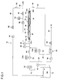
- Fig. 1 is a flow diagram of a reverse osmosis membrane apparatus 10 applied to a seawater desalination plant.
- a to-be-treated water tank 12 in a to-be-treated water tank 12, stored is clarified seawater sw obtained by subjecting raw seawater to pretreatment of sterilization and removal of relatively large foreign substances such as dusts and microbes.
- a clarified seawater supply passage 16 for supplying clarified seawater sw to a reverse osmosis membrane module 14, is connected.
- the clarified seawater sw stored in the to-be-treated water tank 12 is flown into the clarified seawater supply passage 16 by a water supply pump 18 provided in the clarified seawater supply passage 16.
- Impurities in the clarified seawater sw flown into the clarified water supply passage 16 are removed by a safety filter device 20.
- a high-pressure pump 22 is provided on a downstream side of the safety filter device 20, a high-pressure pump 22 is provided.
- the high-pressure pump 22 having an inverter device 22a is a variable flow rate pump of which rotational speed is controllable, and the flow rate of the clarified seawater sw is controlled by the high-pressure pump 22.
- a branched passage 24 is branched from the clarified seawater supply passage 16.
- a power recovery device 26 is provided.
- the power recovery device 26 is a pressure-exchange-type power recovery device to increase a pressure of the clarified seawater sw flown from the branched passage 24 and to send it to a booster pump 54, utilizing a pressure of concentrated seawater cs flown from a concentrated seawater discharging passage 50 which will be described later.
- the power recovery device 26 has, for example, a known structure (for example, see JP 2011-56439 A ).
- the branched passage 24 is connected to the inlet of the power recovery device 26, and a branched passage 28 is connected to the outlet of the power recovery device 26.
- the other end of the branched passage 28 is connected to the clarified seawater supply passage 16 on the upstream side of the reverse osmosis membrane module 14.
- a pressure sensor 30 and a temperature sensor 32 are provided between the joint portion of the branched passage 28 and reverse osmosis membrane module 14.
- the reverse osmosis membrane module 14 has a high pressure vessel 34 and a plurality of reverse osmosis membrane elements 36 arranged in series inside the high pressure vessel 34. At an inlet end of the high pressure vessel 34, an inlet opening 34a to which the clarified seawater supply passage 16 is connected, is formed, and from the inlet opening 34a, the clarified seawater sw is flown into the high pressure vessel 34.
- the reverse osmosis membrane module 14 has a cylindrical shape and has the same configuration as the spiral-type reverse osmosis membrane module 100 as shown in Fig. 6 .
- a center pipe 38 to which permeate water is collected.
- the center pipe 38 of each of the reverse osmosis membrane elements 36 is connected with a connector 40, and permeate water from each of the reverse osmosis membrane elements 36 is joined together in the center pipes 38.
- the intermediate portion is blocked by an end cap 42 so that permeate water from an earlier stage element of the reverse osmosis membrane elements 36 and permeate water from a later stage element of the reverse osmosis membrane elements 36 are not mixed together.
- the internal space of the high pressure vessel 34 is separated with a brine seal 44 provided on an outer peripheral surface of each of the reverse osmosis membrane elements 36.
- the clarified water sw flown from the inlet opening 34a into the high pressure vessel 34 is separated into permeate water pw and concentrated seawater cs with a reverse osmosis membrane provided in the first stage element of the reverse osmosis membrane elements 14.
- An inlet opening 34b is formed at an inlet end of the high pressure vessel 34, and a permeate water sending passage 46 is connected to the inlet opening 34b.
- the permeate water pw from the earlier stage element of the reverse osmosis membrane elements 36 is joined to the center pipe 38, and is flown out to the permeate water sending passage 46 on the earlier stage side via the connector 40 and the inlet opening 34b.
- the permeate water pw flown out to the permeate water sending passage 46 on the earlier stage side is sent to a downstream subsequent process.
- an outlet openings 34c and 34d are formed at the outlet end of the high pressure vessel.
- a permeate water circulation passage 48 is connected to the outlet opening 34c, and a concentrated seawater discharging passage 50 is connected to the outlet opening 34d.
- the permeate water separated with the reverse osmosis membrane provided in the later stage element of the reverse osmosis membrane elements 36 is joined to the center pipe 38, and is flown out to the permeate water circulation passage 48 on the later stage side via the connector 40 and the outlet opening 34c.
- the concentrated seawater cs separated from the permeate water pw by the first stage element of the reverse osmosis membrane elements 36 is flown out from the outlet end of the first stage element of the reverse osmosis membrane elements 36, and flown into the second stage element of the reverse osmosis membrane elements 36 to be separated into permeate water pw and concentrated seawater cs.
- Concentrated seawater cs is thereby separated into permeate water pw and concentrated seawater cs by the reverse osmosis membrane elements 36 sequentially to be concentrated gradually.
- the concentrated seawater cs flown from the last stage element of the reverse osmosis membrane elements 36 is discharged from the outlet opening 34d to the concentrated seawater discharging passage50.
- the concentrated seawater discharging passage 50 is connected to the power recovery device 26.
- the high-pressure concentrated seawater cs flown out to the concentrated seawater discharging passage 50 is flown into the power recovery device 26 to increase the pressure of the clarified seawater sw entered from the branched passage 24 and send out the seawater sw to the branched passage 28.
- the pressure of the clarified seawater sw at the inlet of the high pressure vessel 34 is thereby increased, a part of the power for the high-pressure pump 22 can be provided by the power recovery device 26.
- a concentrated seawater discharging passage 52 is provided, and the concentrated seawater cs having a low pressure and flown out from the power recovery device 26 is discharged from the concentrated seawater discharging passage 52.
- a booster pump 54 is provided, and the pressure of the clarified seawater sw can be increased by the booster pump 54 to increase the flow rate of the clarified seawater.
- the booster pump 54 has provided an inverter device 54a capable of controlling the rotational speed of the pump.
- a flowmeter 56 is provided in the branched passage 24, and a flow regulating valve 58 is provided in the concentrated seawater discharging passage 52.
- a flowmeter 60 In the permeate water sending passage 46, a flowmeter 60, a salinity meter 62 to detect an electric conductivity of the permeate water pw and to obtain the salinity from the detected value, and a flow regulating valve 64 are provided. In the permeate water circulation passage 48, a flowmeter 66 and a flow regulating valve 68 are provided.
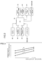
- Fig. 2 is a block diagram illustrating a control system for the reverse osmosis membrane apparatus 10.
- detected values of the pressure sensor 30, the temperature sensor 32, flowmeters 56, 60 and 66, and the salinity meter 62 are input to the controller 70.
- the controller 70 controls the behavior of the water supply pump 18, the high pressure pump 22 and the booster pump 54, and controls the opening degree of the flow regulating valves 58, 64 and 68.
- the permeate water pw having a better water quality from the earlier stage element of the reverse osmosis membrane elements 36 is sent to the downstream subsequent process, and the permeate water pw having a worse water quality from the later stage element of the reverse osmosis membrane elements 36 is returned to the to-be-treated water tank 12.
- the flow rate of the permeate water from the earlier stage element of the reverse osmosis membrane elements 36 is controlled so as to be constant.
- the flow rate of the permeate water from the later stage element of the reverse osmosis membrane elements 36 flowing in the permeate water circulation passage 48 is controlled so that the salinity becomes the reference value.
- Fig. 3 is a chart where the horizontal axis represents the temperature of the clarified seawater sw, and the vertical axis represents the circulation flow rate of the permeate water from the later stage element of the reverse osmosis membrane elements 36.
- each of the three lines represents the circulation flow rate of the permeate water required to satisfy the required value of the water quality of the permeate water: the line A is for a case where the deterioration degree of a reverse osmosis membrane of the reverse osmosis membrane elements 36 is large, the line B is for a case where the deterioration degree of the reverse osmosis membrane is small, and the line C is for a case where the reverse osmosis membrane is not deteriorated.
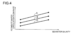
- Fig. 4 is a chart where the horizontal axis represents the salinity of the clarified seawater sw, and the vertical axis represents the circulation flow rate of the permeate water from the later stage element of the reverse osmosis membrane elements 36.
- the circulation flow rate of the permeate water is increased so that the water quality of the permeate water pw satisfies the required value.
- the reverse osmosis membrane is deteriorated, as the water quality of the permeate water pw is declined, the circulation flow rate of the permeate water is increased so that the water quality of the permeate water pw satisfies the required value.
- the control as described above can be automated by using the controller 70.
- the total amount of the permeate water pw from the later stage element of the reverse osmosis membrane elements 14 is returned to the to-be-treated water tank 12.
- a branched passage branched from the permeate water circulation passage 48 and connected to the permeate water sending passage 46 only a part of the permeate water pw may be circulated to the to-be-treated water tank 12. It is thereby possible to facilitate the control of the circulation flow rate of the permeate water.
- a constant flow rate high-pressure pump 72 which is not of a variable flow rate type, is provided in the clarified seawater supply passage 16, and a flow regulating valve 74 is provided on the outlet side of the high-pressure pump 72.
- a booster pump 76 which is not of a variable flow rate type, is provided in the branched passage 28, and a flow regulating valve 78 is provided on the outlet side of the booster pump 76.
- the opening degrees of the flow regulating valves 74 and 78 are controlled by the controller 70. Except for what is specified in the above description, this example has the same configuration as the above embodiment.
- the controller 70 is provided and control of the high-pressure pump 22 and the booster pump 54, and regulation of the flow regulating valves 58, 64, 68, 74 and 78 are automated. However, alternatively, such control may be carried out manually by an operator without providing a controller 70.
- a spiral-type reverse osmosis membrane element 14 is used as the reverse osmosis membrane module.
- a flat membrane-type reverse osmosis membrane element may be employed.
- the present invention may also be applied to, for example, pure water production apparatuses.
- a reverse osmosis membrane apparatus which enables energy-saving operation and stable supply of permeate water while satisfying a required value of the permeate water during operation, is provided.
Landscapes
- Engineering & Computer Science (AREA)
- Water Supply & Treatment (AREA)
- Chemical & Material Sciences (AREA)
- Nanotechnology (AREA)
- Chemical Kinetics & Catalysis (AREA)
- Life Sciences & Earth Sciences (AREA)
- Hydrology & Water Resources (AREA)
- Environmental & Geological Engineering (AREA)
- Organic Chemistry (AREA)
- Separation Using Semi-Permeable Membranes (AREA)
Applications Claiming Priority (2)
| Application Number | Priority Date | Filing Date | Title |
|---|---|---|---|
| JP2013030682A JP6057770B2 (ja) | 2013-02-20 | 2013-02-20 | 逆浸透膜装置の運転方法 |
| PCT/JP2014/053009 WO2014129341A1 (ja) | 2013-02-20 | 2014-02-10 | 逆浸透膜装置の運転方法 |
Publications (2)
| Publication Number | Publication Date |
|---|---|
| EP2959964A1 true EP2959964A1 (de) | 2015-12-30 |
| EP2959964A4 EP2959964A4 (de) | 2016-10-19 |
Family
ID=51391136
Family Applications (1)
| Application Number | Title | Priority Date | Filing Date |
|---|---|---|---|
| EP14754337.5A Withdrawn EP2959964A4 (de) | 2013-02-20 | 2014-02-10 | Verfahren zum betreiben einer umkehrosmose-membranvorrichtung |
Country Status (5)
| Country | Link |
|---|---|
| US (1) | US10294127B2 (de) |
| EP (1) | EP2959964A4 (de) |
| JP (1) | JP6057770B2 (de) |
| SA (1) | SA515360908B1 (de) |
| WO (1) | WO2014129341A1 (de) |
Cited By (1)
| Publication number | Priority date | Publication date | Assignee | Title |
|---|---|---|---|---|
| EP3260424A1 (de) * | 2016-06-24 | 2017-12-27 | Siemens Aktiengesellschaft | Flüssigkeitsbehandlungssystem und -verfahren |
Families Citing this family (8)
| Publication number | Priority date | Publication date | Assignee | Title |
|---|---|---|---|---|
| JP6041798B2 (ja) | 2013-12-20 | 2016-12-14 | 三菱重工業株式会社 | 逆浸透膜濾過装置 |
| US11072551B2 (en) * | 2016-12-12 | 2021-07-27 | A. O. Smith Corporation | Water filtration system with recirculation to reduce total dissolved solids creep effect |
| KR101853214B1 (ko) * | 2016-12-29 | 2018-04-27 | 고려대학교 산학협력단 | 역삼투를 이용한 수처리 장치 |
| CN110382088B (zh) * | 2017-01-09 | 2022-04-19 | 威立雅水务技术支持公司 | 通过反渗透或纳米过滤处理水的系统和方法 |
| WO2018136848A1 (en) * | 2017-01-20 | 2018-07-26 | The Trustees Of Columbia University In The City Of New York | Renewable-powered reverse osmosis desalination with active feedwater salinity control for maximum water production efficiency with variable energy input |
| JPWO2018182033A1 (ja) * | 2017-03-31 | 2020-02-06 | 東レ株式会社 | 造水方法及び造水装置 |
| JP6994376B2 (ja) * | 2017-12-13 | 2022-01-14 | オルガノ株式会社 | 純水製造装置およびその運転方法 |
| JP7196731B2 (ja) * | 2019-03-28 | 2022-12-27 | 栗田工業株式会社 | 純水製造装置及び純水製造方法 |
Family Cites Families (16)
| Publication number | Priority date | Publication date | Assignee | Title |
|---|---|---|---|---|
| US4341629A (en) * | 1978-08-28 | 1982-07-27 | Sand And Sea Industries, Inc. | Means for desalination of water through reverse osmosis |
| JPH04145928A (ja) * | 1990-10-04 | 1992-05-19 | Japan Organo Co Ltd | 逆浸透膜装置およびそれを用いた水処理装置 |
| DE19748997C2 (de) | 1997-11-06 | 2001-05-23 | Schilling Chemie Gmbh U Produk | Verfahren zum Betrieb einer Umkehrosmoseanlage |
| DE19818692C1 (de) * | 1998-04-25 | 1999-07-08 | Schael Wilfried | Verfahren zur meßtechnischen Überwachung einer Umkehrosmoseanlage |
| US6190556B1 (en) * | 1998-10-12 | 2001-02-20 | Robert A. Uhlinger | Desalination method and apparatus utilizing nanofiltration and reverse osmosis membranes |
| JP2001300264A (ja) | 2000-04-28 | 2001-10-30 | Toray Ind Inc | 逆浸透膜造水装置 |
| JP4794235B2 (ja) * | 2005-08-02 | 2011-10-19 | シャープ株式会社 | 発光装置 |
| JP4831480B2 (ja) * | 2006-06-21 | 2011-12-07 | 三浦工業株式会社 | 膜濾過システム |
| JP2008307487A (ja) * | 2007-06-15 | 2008-12-25 | Mitsubishi Heavy Ind Ltd | 脱塩装置 |
| JP5050996B2 (ja) * | 2008-05-19 | 2012-10-17 | 三浦工業株式会社 | 逆浸透膜装置 |
| FR2940140B1 (fr) * | 2008-12-23 | 2011-11-11 | Degremont | Procede et installation pour la gestion du colmatage de modules membranaires et de membranes de filtration |
| JP5535491B2 (ja) * | 2009-02-06 | 2014-07-02 | 三菱重工業株式会社 | スパイラル型海水淡水化装置 |
| FR2946334B1 (fr) | 2009-06-04 | 2011-08-26 | Otv Sa | Procede de traitement d'eau en vue de son dessalement, incluant un traitement des concentrats |
| JP2011056439A (ja) | 2009-09-11 | 2011-03-24 | Toshiba Corp | 動力回収装置 |
| US9616388B2 (en) * | 2013-03-15 | 2017-04-11 | Culligan International Company | Reverse osmosis system with an automated modulated bypass |
| JP2015042385A (ja) * | 2013-08-26 | 2015-03-05 | 株式会社日立製作所 | 淡水化システム |
-
2013
- 2013-02-20 JP JP2013030682A patent/JP6057770B2/ja not_active Expired - Fee Related
-
2014
- 2014-02-10 US US14/768,548 patent/US10294127B2/en not_active Expired - Fee Related
- 2014-02-10 WO PCT/JP2014/053009 patent/WO2014129341A1/ja active Application Filing
- 2014-02-10 EP EP14754337.5A patent/EP2959964A4/de not_active Withdrawn
-
2015
- 2015-08-18 SA SA515360908A patent/SA515360908B1/ar unknown
Cited By (1)
| Publication number | Priority date | Publication date | Assignee | Title |
|---|---|---|---|---|
| EP3260424A1 (de) * | 2016-06-24 | 2017-12-27 | Siemens Aktiengesellschaft | Flüssigkeitsbehandlungssystem und -verfahren |
Also Published As
| Publication number | Publication date |
|---|---|
| SA515360908B1 (ar) | 2017-05-11 |
| US10294127B2 (en) | 2019-05-21 |
| WO2014129341A1 (ja) | 2014-08-28 |
| JP6057770B2 (ja) | 2017-01-11 |
| EP2959964A4 (de) | 2016-10-19 |
| US20160002071A1 (en) | 2016-01-07 |
| JP2014159006A (ja) | 2014-09-04 |
Similar Documents
| Publication | Publication Date | Title |
|---|---|---|
| US10294127B2 (en) | Method of operating reverse osmosis membrane apparatus | |
| US9725339B2 (en) | Reverse osmosis treatment apparatus | |
| US20150158744A1 (en) | Fresh water producing apparatus and method for operating same | |
| US9126853B2 (en) | Fresh water generator | |
| US20130118978A1 (en) | Combined microfiltration or ultrafiltration and reverse osmosis processes | |
| US10322361B2 (en) | Water purifying system and backwash module control method thereof | |
| JP2008307487A (ja) | 脱塩装置 | |
| JP2001239134A (ja) | 逆浸透処理装置の運転方法とその制御装置および造水方法 | |
| JP2012130840A (ja) | 逆浸透処理装置 | |
| KR20170140920A (ko) | 에너지 절약을 위한 역삼투 멤브레인 장치 및 이를 이용한 수처리 방법 | |
| JP5791767B2 (ja) | 逆浸透処理装置 | |
| EP2723477A1 (de) | Hocheffiziente membranfiltration | |
| JP6344457B2 (ja) | 造水方法 | |
| JP6033118B2 (ja) | 逆浸透膜装置 | |
| JP5966639B2 (ja) | 塩水淡水化装置および造水方法 | |
| CN115103820B (zh) | 造水装置的控制方法和运转方法、造水装置的故障判定方法、造水装置和记录介质 | |
| JPWO2018182033A1 (ja) | 造水方法及び造水装置 | |
| JP6506102B2 (ja) | 水処理システム | |
| JP2014034005A (ja) | 塩水淡水化装置および造水方法 | |
| KR101594226B1 (ko) | 담수화장치 | |
| JP6216847B2 (ja) | 逆浸透処理装置 | |
| JP2015033673A (ja) | 膜分離装置および膜分離装置の運転方法 | |
| KR102037008B1 (ko) | 유로 전환 밸브를 이용한 swro 막오염 분산 시스템 및 이를 이용한 swro 막오염 분산 유지관리 방법 | |
| Jang et al. | Effects of the filtration flux and pre-treatments on the performance of a microfiltration drinking water treatment system | |
| JP2015221440A (ja) | 逆浸透処理装置 |
Legal Events
| Date | Code | Title | Description |
|---|---|---|---|
| PUAI | Public reference made under article 153(3) epc to a published international application that has entered the european phase |
Free format text: ORIGINAL CODE: 0009012 |
|
| 17P | Request for examination filed |
Effective date: 20150818 |
|
| AK | Designated contracting states |
Kind code of ref document: A1 Designated state(s): AL AT BE BG CH CY CZ DE DK EE ES FI FR GB GR HR HU IE IS IT LI LT LU LV MC MK MT NL NO PL PT RO RS SE SI SK SM TR |
|
| AX | Request for extension of the european patent |
Extension state: BA ME |
|
| DAX | Request for extension of the european patent (deleted) | ||
| A4 | Supplementary search report drawn up and despatched |
Effective date: 20160916 |
|
| RIC1 | Information provided on ipc code assigned before grant |
Ipc: B01D 61/12 20060101AFI20160912BHEP Ipc: C02F 1/44 20060101ALI20160912BHEP Ipc: B01D 61/58 20060101ALI20160912BHEP |
|
| RAP1 | Party data changed (applicant data changed or rights of an application transferred) |
Owner name: MITSUBISHI HEAVY INDUSTRIES ENGINEERING, LTD. |
|
| STAA | Information on the status of an ep patent application or granted ep patent |
Free format text: STATUS: EXAMINATION IS IN PROGRESS |
|
| 17Q | First examination report despatched |
Effective date: 20180924 |
|
| STAA | Information on the status of an ep patent application or granted ep patent |
Free format text: STATUS: EXAMINATION IS IN PROGRESS |
|
| STAA | Information on the status of an ep patent application or granted ep patent |
Free format text: STATUS: THE APPLICATION IS DEEMED TO BE WITHDRAWN |
|
| 18D | Application deemed to be withdrawn |
Effective date: 20220803 |