EP2959800A1 - Vorrichtung zur lösbaren kopplung einer aussenlade mit einer innenlade sowie ein möbel - Google Patents
Vorrichtung zur lösbaren kopplung einer aussenlade mit einer innenlade sowie ein möbel Download PDFInfo
- Publication number
- EP2959800A1 EP2959800A1 EP15172727.8A EP15172727A EP2959800A1 EP 2959800 A1 EP2959800 A1 EP 2959800A1 EP 15172727 A EP15172727 A EP 15172727A EP 2959800 A1 EP2959800 A1 EP 2959800A1
- Authority
- EP
- European Patent Office
- Prior art keywords
- drawer
- lever
- front panel
- driving lever
- driving
- Prior art date
- Legal status (The legal status is an assumption and is not a legal conclusion. Google has not performed a legal analysis and makes no representation as to the accuracy of the status listed.)
- Granted
Links
- 230000004913 activation Effects 0.000 claims abstract description 59
- 238000010168 coupling process Methods 0.000 claims abstract description 40
- 230000008878 coupling Effects 0.000 claims abstract description 37
- 238000005859 coupling reaction Methods 0.000 claims abstract description 37
- 238000006073 displacement reaction Methods 0.000 claims description 2
- 238000013459 approach Methods 0.000 description 2
- 230000008859 change Effects 0.000 description 2
- 230000009471 action Effects 0.000 description 1
- 230000003213 activating effect Effects 0.000 description 1
- 230000006978 adaptation Effects 0.000 description 1
- 230000008901 benefit Effects 0.000 description 1
- 230000005540 biological transmission Effects 0.000 description 1
- 230000006835 compression Effects 0.000 description 1
- 238000007906 compression Methods 0.000 description 1
- 238000010276 construction Methods 0.000 description 1
- 230000001419 dependent effect Effects 0.000 description 1
- 238000004519 manufacturing process Methods 0.000 description 1
Images

Classifications
-
- A—HUMAN NECESSITIES
- A47—FURNITURE; DOMESTIC ARTICLES OR APPLIANCES; COFFEE MILLS; SPICE MILLS; SUCTION CLEANERS IN GENERAL
- A47B—TABLES; DESKS; OFFICE FURNITURE; CABINETS; DRAWERS; GENERAL DETAILS OF FURNITURE
- A47B88/00—Drawers for tables, cabinets or like furniture; Guides for drawers
- A47B88/70—Coupled drawers
- A47B88/75—Coupled drawers the secondary drawer being in or above the primary drawer
- A47B2088/76—Coupling means therefor
Definitions
- the invention relates to a device for releasably coupling an external drawer with an inner drawer according to the preamble of claim 1 and a piece of furniture with such a device.
- An interior of a drawer furniture can be known to be additionally divided by an inner drawer, hereinafter called inner drawer.
- inner drawer usually a front side of the inner drawer, in particular the front panel of a front panel of a surrounding drawer, hereinafter called outer drawer, covered.
- a front side of the drawer unit can thereby have a relatively closed front side.
- the invention has for its object to provide a device for releasably coupling an outdoor drawer with an inner drawer, which is relatively easy to manufacture and assemble.
- the invention is based on a device for detachable coupling of an external drawer with an inner drawer, wherein the outer drawer and the inner drawer are movably mounted in a piece of furniture.
- the device comprises a pivotally mounted driving lever with a hook element for hooking on the inner drawer.
- the essence of the invention is that the driving lever is pivotally mounted with a pivot about an axis of rotation, which is arranged in the assembled state parallel to a main plane of the front panel of the outer drawer, and that an activation lever is provided, with the driving lever with the hook element in a hooked position on the front panel of the inner drawer can be brought into a driving position when the front panel of the inner drawer meets the activation lever.
- the activation lever advantageous another means for controlling a coupling operation of the outer load on the inner drawer available. In this case, it can be ensured with the activation lever nesting of outer drawer and inner drawer, if, for example, when approaching the front panels of the inner drawer and the outer drawer a predetermined distance between the front panels is below.
- the activation lever in particular by reducing the size of a gap between the front panels be movable so that the hook member on the inner tray is engageable by a movement coupling between the activation lever and the driving lever.
- An entrainment of the inner drawer can be achieved regardless of a weight and shape of the driving lever and the hook element.
- entrainment is also particularly independent of an additionally applied to the driving lever, for example, elastically yielding force, so that the driving lever can hold out in a decoupled arrangement with an example elastic force from a gap between the front panels.
- the force direction is preferably adapted to the coupling process, for example, a pivoting movement of the driving lever.
- a pivoting movement of the driving lever can be provided in a coupling process, for example, to bring the hook element in a the front panel of the inner load engaging behind entrainment position.
- the activation lever is preferably long, in particular designed to be longer than the driving lever.
- the activation lever is provided with a smooth contact surface for contact with the front panel of the inner drawer.
- the contact surface may be e.g. be shaped, in particular curved, that the activation lever touches the front panel of the inner drawer with an at least approximately flat surface area. This can protect an outer surface of the front panel of the inner drawer and protect it from damage.
- At one end point of a coupling movement of the activation lever can be arranged between the front panels of the outer drawer and the inner drawer, characterized in that a direct contact of the two front panels is advantageously avoided. Furthermore, can be provided by the device according to the invention advantageously an automatic coupling of the inner drawer to the outer drawer.
- the activation lever can be attached, for example, with one end preferably on an inner side of the front panel movable, in particular pivotally mounted.
- the activation lever is preferably movable into a projecting from the inside and in particular in the direction of a front panel of the inner drawer projecting position.
- the activation lever may be pivotable, for example, from the protruding position into a position in which the activation lever, for example, on an inwardly facing surface of the front panel of the outer tray rests.
- a range of movement of the activation lever is preferably matched to the driving lever and in particular to the hook element such that a decoupling of the device from the inner drawer, for example an upper edge of the front panel of the inner drawer is ensured by a movement of the activation lever in the above position.
- An approximation of the front panels of the outer drawer and the inner drawer for example, be limited by the fact that the activation lever is arranged in an activated end position, for example on both front panels in particular parallel adjacent.
- a movement coupling between the activation lever and the driving lever is provided, through which a driving position of the driving lever and the hook element can be reached in the activated end position of the activation lever.
- the device according to the invention has a comparatively simple construction, which can be composed of few parts.
- the invention can advantageously be carried out in such a way that a special adaptation or processing of the front panel of the inner drawer for a coupling hooking the hook element is avoidable.
- a movement coupling of the driving lever with the activation lever e.g. a transmission - for example with levers or e.g. toothed elements - be provided.
- the activation lever and the driving lever can be directly connected or in contact.
- the driving lever and the activation lever are preferably fixedly connected to each other, wherein the driving lever and the activation lever can be formed in particular as a single body of a continuous contiguous material.
- a longitudinal axis of the driving lever and a longitudinal axis of the activation lever are preferably to each other angled, in particular arranged at a right angle.
- the activation lever may be movable together with the drive lever, in particular pivotally mounted preferably on the pivot bearing.
- the axis of rotation of the pivot bearing can be arranged at right angles to the two longitudinal axes.
- the driving lever and in particular the hook element can be provided and designed for hooking or engaging behind the front panel of the inner drawer.
- a coupled state of the inner drawer on the outer drawer for a user can be seen relatively quickly when the pivotally mounted driving lever and in particular the hook element are provided for hooking on an upper side, in particular on an upper edge of the front panel of the inner drawer.
- a preferred embodiment of the invention may comprise an actuating element which is designed for a displaceable attachment to the front panel of the outer drawer, wherein the driving lever is rotatably mounted on the actuating element.
- the pivot bearing of the driving lever can be formed on the actuating element.
- the entrainment coupling can be released by pushing the actuating element away from the front panel of the inner drawer, in particular from the narrow side. Together with the displaceable actuating element while the pivot bearing of the driving lever is removable from the inner drawer. An entanglement of the driving lever on the inner drawer can be avoided, for example, by the movement coupling with the activation lever.
- mutually associated, mutually movable stop sections may be present on the pivot bearing, with which a pivoting movement for hooking the driving lever is limited.
- a first stop section of a corresponding stop pair may be fixedly connected to the actuating element, while a second stop section of the stop pair may be fixed in place, e.g. can be arranged on the driving lever.
- a displacement spring is provided on the actuating element, which can move away the actuating element from a decoupling position, wherein the hook element of the driving lever is removed from a engaging engagement on the inner drawer.
- spring means may be provided with which the driving lever in a standby position for hooking the front panel of the inner drawer is durable.
- the driving lever in the standby position e.g. pointing obliquely upward from an inner side of the front panel of the outer tray, e.g. pointing in the direction of the furniture body.
- the activation lever is then provided to overcome the lifting action of the spring means and to lower the driving lever for engagement of the hook member.
- the activation lever can be, for example, also by the spring means in a position on the front panel of the outer drawer projecting inward position.
- a part of the spring means may be anchored to the actuating element, wherein a second anchorage for the spring means may be provided on the driving lever and / or on the activation lever.
- the spring means may be adapted to frictional forces of a guide of the inner drawer, that in a coupled position, the spring forces of the spring means not to sufficient to overcome frictional forces to move the inner drawer away from the outer drawer. As a result, decoupling of the device remains substantially under the control of the user.
- the driving lever and the activation lever are held in a standby position on the actuating element such that, during a hooking operation, the driving lever is displaced upward with the activation lever on the actuating element.
- an automatic coupling through the device is also achievable when the inner drawer has taken a different altitude depending on the load condition.
- the driving lever can engage in a driving position via latching means.
- latching means By means of the latching means it can additionally be avoided that the driving lever and in particular the hook element detach themselves from a coupling position automatically.
- the latching means are, for example, such that the detent is released in the driving position by displacing the driving lever with the actuating element upwards.
- the driving lever can pivot with the activation lever in a hitting the front panel of the inner slide upwards and moves into the ready position.
- the latching means unintentional release of the driving lever by a pivoting movement in e.g. the standby position is difficult or blocked.
- FIGS. 1 to 3 an exemplary example of a coupling device 6 according to the invention is shown on a piece of furniture 1, with which an inner drawer 3 can be coupled to an outer drawer 2 for entrainment, in particular when the outer drawer is pulled out. From the furniture 1 are in FIG. 1 only the inner drawer 3 and partially a front panel 2a of the outer drawer 2 shown.
- an actuating element 7 of the coupling device 6 is slidably mounted on an area portion 2b of the inside of the front panel 2a.
- the actuator 7 is mounted vertically displaceable on the inside of the front panel 2a.
- a pivot bearing 11 is formed, on which a driving lever 8 is pivotally connected to the actuating element 7.
- the driving lever 8 is mounted about a horizontal axis of rotation up and down pivotally mounted on the pivot bearing 11.
- Fig.1 the take-off lever 8 is shown in an upwardly pivoted standby position, wherein the same driving lever is represented by the reference numeral 8 'in a position coupling the inner load 3 to the outer load 2.
- a hook member 9 At a free-standing end portion of the driving lever 8, a hook member 9. In the coupling position of the driving lever 8 ', the same hook element 9' is provided to engage behind a front panel 4 of the inner tray 3. By concerns on an inner surface portion 4c of the front panel 4, the hook member 9 'in the coupling position, the inner tray 3 move along when the outer tray 2 is pulled out of the furniture 1.
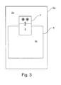
- a coupled state is from a perspective looking at the furniture 1 from inside to outside FIG. 3 shown.
- the driving lever 8 is in particular fixedly connected to an activation lever 10, wherein the activation lever 10 and the driving lever 8 are preferably formed as a one-piece component.
- the activation lever 10 By the connection of the activation lever 10 with the driving lever 8 an immediate movement coupling of the two levers 8 and 10 is provided.
- the activating lever 10 When the driving lever 8 is in the standby position, the activating lever 10 is disposed with a free-standing end portion protruding from the inward facing area 2b of the front panel 2a of the outside tray 2.
- the front panel 4 of the inner drawer and the front panel 2a of the outer drawer 2 are approximated to one another such that the same activation lever 10 'rests in parallel on both front panels 2 and 4.
- Fig.2 is a section of Fig.l shown with further details.
- the actuator 7 is pressed by means of a spring 13 down and can be to release a coupling of the inner tray 3 to the outer drawer 2 pull against the force of the spring 13 upwards, at the same time the driving lever 8 and the activation lever 10 are moved upward.
- the activation lever 10 engages as a spring means, for example, a compression spring 12 which holds the activation lever 10 yielding in a protruding from the inner surface portion 2b position. Due to the connection of the activation lever 10 with the driving lever 8 thereby the driving lever 8 is held in the standby position for coupling the inner tray 3. In the course of coupling the inner drawer 3, the front panel 4 approaches the front panel 2a, thereby pivoting the activation lever 10 down into a position parallel between two front panels 2a and 4. Due to the movement coupling with the activation lever 10 of the driving lever 8 is moved down and the hook member 9 behind the front panel 4 of the inner tray 3.
- a spring means for example, a compression spring 12 which holds the activation lever 10 yielding in a protruding from the inner surface portion 2b position. Due to the connection of the activation lever 10 with the driving lever 8 thereby the driving lever 8 is held in the standby position for coupling the inner tray 3. In the course of coupling the inner drawer 3, the front panel 4 approaches the front panel 2a
- Fig.2 are an upper altitude B and lower altitude C a top 4b of the front panel 4 of the inner tray 3 with respect to a position A of the pivot bearing 11 shown.
- the altitude B may correspond to a less heavily loaded state of the inner tray 3 than the altitude C.
- the actuating element 7 is located in a downwardly pressed position on the front panel 2a of the outer drawer 2, which is required in particular for the ready position of the driving lever 8.
- the coupling device 6 is mounted on the front panel 2 a such that a coupling of the inner tray 3 at both altitudes B and C is possible.
- the activation lever 10 When the inner tray 3 is in the high position C, only the activation lever 10 and the outer surface area 4 a of the front panel 4 of the inner tray 3 are in contact with a coupling.
- the front panel 4 When the inner tray 3 is in the high position B, the front panel 4 may be simultaneously in contact with the driving lever 8 and the activation lever 10.
- the activation lever 10 is formed so long in particular in the longitudinal direction that with the contact point of the activation lever 10, a greater lever moment is achievable, as with a contact point of the driving lever 8, which is struck by an upper edge 4d of the front panel. As a result, the driving lever 8 can be supported on the upper edge 4d.
- the coupling device 6 offers the advantage that the coupling device 6 makes it possible to couple the inner load 3 to the outer load 2 in, for example, different loading states of the inner load 3 and outer load 2.
Abstract
Description
- Die Erfindung betrifft eine Vorrichtung zur lösbaren Kopplung einer Außenlade mit einer Innenlade nach dem Oberbegriff des Anspruchs 1 sowie ein Möbel mit einer solchen Vorrichtung.
- Ein Innenraum eines Schubladenmöbels kann bekanntlich durch eine innere Schublade, nachfolgend Innenlade genannt, zusätzlich aufgeteilt sein. Dabei ist üblicherweise eine Vorderseite der Innenlade, insbesondere deren Frontblende von einer Frontblende einer umgebenden Schublade, nachfolgend Außenlade genannt, verdeckt. Eine Frontseite des Schubladenmöbels kann dadurch eine relativ geschlossene Frontseite aufweisen. Zum Bewegen der Innenlade sind auf dem Gebiet des Möbelbaus eine Vielzahl von Vorrichtungen zur lösbaren Kopplung einer Außenlade mit einer Innenlade in verschiedensten Ausführungen bekannt.
- Der Erfindung liegt die Aufgabe zugrunde, eine Vorrichtung zur lösbaren Kopplung einer Außenlade mit einer Innenlade bereitzustellen, die vergleichsweise einfach herstellbar und montierbar ist.
- Die Aufgabe wird durch eine Vorrichtung mit den Merkmalen des Anspruchs 1 gelöst.
- Bevorzugte und vorteilhafte Ausführungen der Erfindung sind in den abhängigen Ansprüchen genannt.
- Die Erfindung geht von einer Vorrichtung zur lösbaren Kopplung einer Außenlade mit einer Innenlade aus, wobei die Außenlade und die Innenlade in einem Möbel bewegbar angebracht sind. Die Vorrichtung umfasst einen schwenkbar gelagerten Mitnahmehebel mit einem Hakenelement für ein Einhaken an der Innenlade.
- Der Kern der Erfindung besteht darin, dass der Mitnahmehebel mit einem Drehlager um eine Drehachse schwenkbar gelagert ist, die im montierten Zustand parallel zu einer Hauptebene der Frontblende der Außenlade angeordnet ist, und dass ein Aktivierungshebel vorgesehen ist, mit dem der Mitnahmehebel mit dessen Hakenelement in eine eingehakte Position an der Frontblende der Innenlade in eine Mitnahmeposition bringbar ist, wenn die Frontblende der Innenlade auf den Aktivierungshebel trifft. Zusätzlich zum Mitnahmehebel steht mit dem Aktivierungshebel vorteilhaft ein weiteres Mittel zur Kontrolle eines Kopplungsvorgangs der Außenlade an der Innenlade zur Verfügung. Dabei lässt sich mit dem Aktivierungshebel ein Aneinanderkoppeln von Außenlade und Innenlade sichergestellen, wenn beispielsweise bei einer Annäherung der Frontblenden der Innenlade und der Außenlade ein vorgegebener Abstand zwischen den Frontblenden unterschritten ist. Dabei kann der Aktivierungshebel insbesondere durch ein Verkleinern eines Zwischenraums zwischen den Frontblenden derart bewegbar sein, dass durch eine Bewegungskopplung zwischen dem Aktivierungshebel und dem Mitnahmehebel das Hakenelement an der Innenlade in Eingriff versetzbar ist. Eine Mitnahme der Innenlade kann dabei unabhängig von eine Gewichtskraft und Form des Mitnahmehebels und des Hakenelements erreichbar sein. Des Weiteren ist eine Mitnahme auch insbesondere unabhängig von einer zusätzlich auf den Mitnahmehebel aufgebrachten z.B. elastisch nachgiebigen Kraft, so dass der Mitnahmehebel bei einer entkoppelten Anordnung mit einer z.B. elastischen Kraft aus einem Zwischenraum zwischen den Frontblenden heraushalten lässt. Mit Hilfe des Aktivierungshebels lässt sich des Weiteren vorteilhaft einfach eine zusätzliche Kraft für einen zumindest teilweise selbsttätigen Koppelvorgang bereitstellen, deren Kraftrichtung von Bewegungsrichtungen der Außen- und der Innenlade unabhängig ist. Die Kraftrichtung ist vorzugsweise an den Koppelvorgang, z.B. eine Schwenkbewegung des Mitnahmehebels, angepasst. Eine Schwenkbewegung des Mitnahmehebels kann bei einem Koppelvorgang beispielsweise dazu vorgesehen sein, das Hakenelement in eine die Frontblende der Innenlade hintergreifende Mitnahmeposition zu bringen.
- Der Aktivierungshebel ist dabei vorzugsweise lang, insbesondere länger als der Mitnahmehebel ausgebildet. Dadurch können bei einem Auftreffen und bei einer z.B. gleitenden Berührung des Aktivierungshebels an der Frontblende der Innenlade vorteilhaft relativ kleine Kräfte wirksam sein, wenn sich die Frontblenden von Innenlade und Außenlade einander annähern. Vorzugsweise ist der Aktivierungshebel mit einer glatten Kontaktfläche für Berührungen mit der Frontblende der Innenlade versehen. Dabei kann die Kontaktfläche z.B. derart geformt, insbesondere gewölbt sein, dass der Aktivierungshebel mit einem zumindest näherungsweise ebenen Flächenbereich die Frontblende der Innenlade berührt. Hierdurch lässt sich eine äußere Oberfläche der Frontblende der Innenlade schonen und vor Beschädigung schützen.
- An einem Endpunkt einer koppelnden Bewegung kann der Aktivierungshebel so zwischen den Frontblenden der Außenlade und der Innenlade angeordnet sein, dass dadurch ein unmittelbarer Kontakt der beiden Frontblenden vorteilhaft vermeidbar ist. Des Weiteren lässt sich durch die erfindungsgemäße Vorrichtung vorteilhaft eine selbsttätige Ankopplung der Innenlade an die Außenlade bereitstellen.
- Der Aktivierungshebel kann z.B. mit einem Ende vorzugsweise an einer Innenseite der Frontblende beweglich, insbesondere schwenkbar angebracht sein. Dabei ist der Aktivierungshebel vorzugsweise in eine von der Innenseite abstehende und insbesondere in Richtung einer Frontblende der Innenlade vorstehende Position bewegbar. Für eine Aktivierung kann der Aktivierungshebel aus z.B. der vorstehenden Position in eine Position schwenkbar sein, in der der Aktivierungshebel z.B. an einer nach innen gerichteten Oberfläche der Frontblende der Außenlade anliegt. Ein Bewegungsbereich des Aktivierungshebels ist dabei vorzugsweise auf den Mitnahmehebel und insbesondere auf das Hakenelement derart abgestimmt, dass durch eine Bewegung des Aktivierungshebels in die vorstehende Position ein Entkoppeln der Vorrichtung von der Innenlade, z.B. eine Oberkante der Frontblende der Innenlade, sichergestellt ist. Eine Annäherung der Frontblenden der Außenlade und der Innenlade kann z.B. dadurch begrenzt sein, dass der Aktivierungshebel in einer aktivierten Endstellung z.B. an beiden Frontblenden insbesondere parallel anliegend angeordnet ist.
- Dabei ist eine Bewegungskopplung zwischen dem Aktivierungshebel und dem Mitnahmehebel vorgesehen, durch die in der aktivierten Endstellung des Aktivierungshebels eine Mitnahmeposition des Mitnahmehebels und des Hakenelements erreichbar ist.
- Die erfindungsgemäße Vorrichtung weist einen vergleichsweise einfachen Aufbau auf, der aus wenigen Teilen zusammengesetzt sein kann. Dabei lässt sich die Erfindung vorteilhaft in einer Weise ausführen, dass eine besondere Anpassung oder Bearbeitung der Frontblende der Innenlade für ein koppelndes Einhaken des Hakenelements vermeidbar ist.
- Für eine Bewegungskopplung des Mitnahmehebels mit dem Aktivierungshebel kann z.B. ein Getriebe - beispielsweise mit Hebeln oder z.B. verzahnten Elementen - vorgesehen sein. Außerdem können der Aktivierungshebel und der Mitnahmehebel unmittelbar miteinander verbunden bzw. in Berührung sein.
- Für eine vergleichsweise einfache Ausführung der Erfindung sind der Mitnahmehebel und der Aktivierungshebel vorzugsweise fest miteinander verbunden, wobei der Mitnahmehebel und der Aktivierungshebel insbesondere als ein einziger Körper eines durchgehend zusammenhängenden Materials ausgebildet sein können. Eine Längsachse des Mitnahmehebels und eine Längsachse des Aktivierungshebels sind dabei vorzugsweise zueinander angewinkelt, insbesondere in einem rechten Winkel angeordnet. Der Aktivierungshebel kann dabei gemeinsam mit dem Mitnahmehebel beweglich, insbesondere schwenkbar vorzugsweise am Drehlager gelagert sein. Die Drehachse des Drehlagers kann dabei rechtwinklig zu den beiden Längsachsen angeordnet sein.
- Der Mitnahmehebel und insbesondere das Hakenelement können für ein Einhaken bzw. Hintergreifen der Frontblende der Innenlade vorgesehen und ausgebildet sein. Bei einem Einhaken an der Frontblende kann ein gekoppelter Zustand der Innenlade an der Außenlade für einen Benutzer relativ schnell erkennbar sein, wenn der schwenkbar gelagerte Mitnahmehebel und insbesondere das Hakenelement für ein Einhaken an einer Oberseite, insbesondere an einer Oberkante der Frontblende der Innenlade vorgesehen sind.
- Eine bevorzugte Ausführung der Erfindung kann ein Betätigungselement umfassen, das für eine verschiebbare Anbringung an der Frontblende der Außenlade ausgestaltet ist, wobei am Betätigungselement der Mitnahmehebel drehbar gelagert ist. Dabei kann das Drehlager des Mitnahmehebels am Betätigungselement ausgebildet sein. Durch Verschieben des Betätigungselements können z.B. veränderte Positionen der Außenlade und der Innenlade zueinander ausgeglichen werden, wobei eine Positionsveränderung z.B. eine Veränderung der Beladung der Außenlade bzw. der Innenlade hervorgerufen sein kann. Des Weiteren erlaubt ein verschiebbares Betätigungselement, ohne eine Schwenkbewegung des Mitnahmehebels das Hakenelement von der Innenlade und insbesondere von deren Frontblende zu lösen. Wenn beispielsweise der Mitnahmehebel mit dem Hakenelement an z.B. einer Schmalseite der Frontblende der Innenlade eingehakt ist, lässt sich die Mitnahmekopplung durch ein Wegschieben des Betätigungselements von der Frontblende der Innenlade, insbesondere von der Schmalseite lösen. Gemeinsam mit dem verschiebbaren Betätigungselement ist dabei das Drehlager des Mitnahmehebels von der Innenlade entfernbar. Ein Verhaken des Mitnahmehebels an der Innenlade lässt sich dabei z.B. durch die Bewegungskopplung mit dem Aktivierungshebel vermeiden.
- Um ein Verhaken des Mitnahmehebels an der Innenlade zu vermeiden, können des Weiteren am Drehlager paarweise einander zugeordnete, zueinander bewegliche Anschlagabschnitte vorhanden sein, mit denen eine Schwenkbewegung zum Einhaken des Mitnahmehebels begrenzt ist. Ein erster Anschlagabschnitt eines entsprechenden Anschlagpaares kann dabei mit dem Betätigungselement ortsfest verbunden sein, während ein zweiter Anschlagabschnitt des Anschlagpaares ortfest z.B. am Mitnahmehebel angeordnet sein kann.
- Vorzugsweise ist am Betätigungselement eine Verschiebefeder vorgesehen, die das Betätigungselement von einer Entkopplungsposition wegbewegen kann, bei der das Hakenelement des Mitnahmehebels aus einem mitnehmenden Eingriff an der Innenlade entfernt ist. Dadurch kann im Regelfall, z.B. ohne besondere Maßnahme von einem Benutzer ein gekoppelter Zustand der Außenlade an der Innenlade begünstigt sein.
- Für eine bevorzugte Ausführung der Erfindung können Federmittel vorgesehen sein, mit denen der Mitnahmehebel in einer Bereitschaftsposition für ein Einhaken der Frontblende der Innenlade haltbar ist. In einem montierten Zustand der Vorrichtung kann der Mitnahmehebel in der Bereitschaftsposition z.B. schräg nach oben zeigend von einer Innenseite der Frontblende der Außenlade z.B. in Richtung des Möbelkorpus weisen. Der Aktivierungshebel ist dann dazu vorgesehen, die Hebewirkung der Federmittel zu überwinden und den Mitnahmehebel für ein Eingreifen des Hakenelements abzusenken. Dabei der Aktivierungshebel lässt sich dabei z.B. ebenfalls durch die Federmittel in einer an der Frontblende der Außenlade nach innen abstehenden Stellung halten. Ein Teil der Federmittel kann dabei am Betätigungselement verankert sein, wobei eine zweite Verankerung für die Federmittel am Mitnahmehebel und/oder am Aktivierungshebel bereitgestellt sein kann.
- Die Federmittel können derart auf Reibungskräfte einer Führung der Innenlade abgestimmt sein, dass in einer gekoppelten Stellung die Federkräfte des Federmittels nicht dazu ausreichen, Reibungskräfte zu überwinden, um die Innenlade von der Außenlade weg zu bewegen. Dadurch bleibt ein Entkoppeln der Vorrichtung im Wesentlichen unter der Kontrolle des Benutzers.
- Vorzugsweise sind der Mitnahmehebel und der Aktivierungshebel derart in einer Bereitschaftsposition an dem Betätigungselement gehalten, dass während eines Einhakens der Mitnahmehebel mit dem Aktivierungshebel am Betätigungselement nach oben verschoben wird. Dadurch ist eine selbsttätige Kopplung durch die Vorrichtung auch dann erreichbar, wenn die Innenlade je nach Beladungszustand eine unterschiedliche Höhenlage eingenommen hat.
- Der Mitnahmehebel kann in einer Mitnahmeposition über Einrastmittel einrasten. Durch die Einrastmittel kann zusätzlich vermieden werden, dass sich der Mitnahmehebel und insbesondere das Hakenelement selbsttätig aus einer koppelnden Stellung lösen. Die Einrastmittel sind beispielsweise dergestalt, dass durch ein Verschieben des Mitnahmehebels mit dem Betätigungselement nach oben die Rastung in der Mitnahmeposition gelöst wird. Damit kann der Mitnahmehebel mit dem Aktivierungshebel bei einem Anschlagen der Frontblende des Innenschubs nach oben schwenken und verfährt in die Bereitschaftsstellung. Durch die Einrastmittel kann ein unbeabsichtigtes Lösen des Mitnahmehebels durch eine Schwenkbewegung in z.B. die Bereitsschaftsposition erschwert oder blockiert sein.
- Nachfolgend wird die Erfindung an einem Ausführungsbeispiel erläutert und anhand von Zeichnungen, die nicht maßstäblich sind, beschrieben. Es zeigen:
- Figur 1
- eine schematische Seitenansicht eines Ausschnitts eines Möbels mit einer erfindungsgemäßen Koppelvorrichtung,
- Figur 2
- einen vergrößerten Ausschnitt aus der
Figur 1 , - Figur 3
- eine schematische Frontalansicht der Innenseiten von Frontblenden einer Innenlade und einer Außenlade in gekoppeltem Zustand.
- In den
Figuren 1 bis 3 ist ein Ausführungsbespiel einer erfindungsgemäßen Koppelvorrichtung 6 an einem Möbel 1 gezeigt, mit der sich eine Innenlade 3 an eine Außenlade 2 für eine Mitnahme insbesondere bei einem Herausziehen der Außenlade koppeln lässt. Von dem Möbel 1 sind inFigur 1 nur die Innenlade 3 und ausschnittsweise eine Frontblende 2a der Außenlade 2 dargestellt. - An einem Flächenabschnitt 2b der Innenseite der Frontblende 2a ist ein Betätigungselement 7 der Koppelvorrichtung 6 verschiebbar angebracht. Das Betätigungselement 7 ist dabei an der Innenseite der Frontblende 2a vertikal verschiebbar gelagert.
- An einem unteren Endabschnitt des Betätigungselements 7 ist ein Drehlager 11 ausgebildet, an dem ein Mitnahmehebel 8 schwenkbar mit dem Betätigungselement 7 verbunden ist. Der Mitnahmehebel 8 ist dabei um eine horizontale Drehachse nach oben und nach unten schwenkbar am Drehlager 11 gelagert. In
Fig.1 ist der Mitnahmehebel 8 in einer nach oben geschwenkten Bereitschaftsposition gezeigt, wobei derselbe Mitnahmehebel mit dem Bezugszeichen 8' in einer die Innenlade 3 an die Außenlade 2 koppelnden Stellung dargestellt ist. - An einem freistehenden Endabschnitt weist der Mitnahmehebel 8 ein Hakenelement 9 auf. In der koppelnden Stellung des Mitnahmehebels 8' ist dasselbe Hakenelement 9' dafür vorgesehen, eine Frontblende 4 der Innenlade 3 zu hintergreifen. Durch Anliegen an einem innenliegenden Flächenabschnitt 4c der Frontblende 4 kann das Hakenelement 9' in der koppelnden Stellung die Innenlade 3 mitbewegen, wenn die Außenlade 2 aus dem Möbel 1 herausgezogen wird.
- Ein gekoppelter Zustand ist aus einer am Möbel 1 von Innen nach Außen blickenden Perspektive in
Figur 3 gezeigt. - Im Bereich des Drehlagers 11 ist der Mitnahmehebel 8 insbesondere fest mit einem Aktivierungshebel 10 verbunden, wobei der Aktivierungshebel 10 und der Mitnahmehebel 8 vorzugsweise als ein einstückiges Bauteil ausgebildet sind. Durch die Verbindung des Aktivierungshebels 10 mit dem Mitnahmehebel 8 ist eine unmittelbare Bewegungskopplung der beiden Hebel 8 und 10 bereitgestellt. Wenn sich der Mitnahmehebel 8 in der Bereitschaftsposition befindet, ist der Aktivierungshebel 10 mit einem freistehenden Endabschnitt von dem nach Innen weisenden Flächenbereich 2b der Frontblende 2a der Außenlade 2 abstehend angeordnet. In einem gekoppelten Zustand der Innenlade 3 mit der Außenlade 2 sind die Frontblende 4 der Innenlade und die Frontblende 2a der Außenlade 2 derart einander angenähert, dass derselbe Aktivierungshebel 10' parallel an beiden Frontblenden 2 und 4 anliegt.
- In
Fig.2 ist ein Ausschnitt der Fig.l mit weiteren Einzelheiten dargestellt. Das Betätigungselement 7 ist mittels einer Feder 13 nach unten gedrückt und lässt sich zum Lösen eine Kopplung der Innenlade 3 an die Außenlade 2 gegen die Kraft der Feder 13 nach oben ziehen, wobei gleichzeitig auch der Mitnahmehebel 8 und der Aktivierungshebel 10 nach oben bewegt werden. - Am Aktivierungshebel 10 greift als Federmittel eine z.B. Druckfeder 12 an, die den Aktivierungshebel 10 nachgiebig in einer vom inneren Flächenabschnitt 2b abstehenden Stellung gedrückt hält. Aufgrund der Verbindung des Aktivierungshebels 10 mit dem Mitnahmehebel 8 wird dadurch der Mitnahmehebel 8 in der Bereitschaftsposition für ein Ankoppeln der Innenlade 3 gehalten. Im Zuge eines Ankoppelns der Innenlade 3 nähert sich die Frontblende 4 an die Frontblende 2a an und schwenkt dabei den Aktivierungshebel 10 nach unten in eine zwischen beiden Frontblenden 2a und 4 parallel anliegende Stellung. Aufgrund der Bewegungskopplung mit dem Aktivierungshebel 10 wird der Mitnahmehebel 8 nach unten und das Hakenelement 9 hinter die Frontblende 4 der Innenlade 3 bewegt.
- In
Fig.2 sind dabei eine obere Höhenlage B und untere Höhenlage C einer Oberseite 4b der Frontblende 4 der Innenlade 3 bezüglich einer Position A des Drehlagers 11 dargestellt. Hierbei kann die Höhenlage B einem weniger stark beladenen Zustand der Innenlade 3 als dem der Höhenlage C entsprechen. Das Betätigungselement 7 befindet sich in einer nach unten gedrückten Stellung an der Frontblende 2a der Außenlade 2, die insbesondere für die Bereitschaftsposition des Mitnahmehebels 8 erforderlich ist. Die Koppelvorrichtung 6 ist dabei derart an der Frontblende 2a angebracht, dass ein Ankoppeln der Innenlade 3 bei beiden Höhenlagen B und C möglich ist. Wenn sich die Innenlade 3 in der Höhenlage C befindet, sind bei einem Ankoppeln nur der Aktivierungshebel 10 und der äußere Flächenbereich 4a der Frontblende 4 der Innenlade 3 in Kontakt. Wenn sich die Innenlade 3 in der Höhenlage B befindet, kann die Frontblende 4 gleichzeitig mit dem Mitnahmehebel 8 und dem Aktivierungshebel 10 in Kontakt stehen. Vorzugsweise ist der Aktivierungshebel 10 derart insbesondere in Längsrichtung lang ausgebildet, dass mit der Kontaktstelle des Aktivierungshebels 10 ein größeres Hebelmoment erreichbar ist, als mit einer Kontaktstelle des Mitnahmehebels 8, die von einer Oberkante 4d der Frontblende getroffen wird. Dadurch lässt sich der Mitnahmehebel 8 an der Oberkante 4d abstützen. Wenn die Frontblenden 2 und 4 weiter einander angenähert werden, ist vom Aktivierungshebel 10 auf den Mitnahmehebel 8 ein Hebelmoment übertragbar, mit welchem der Mitnahmehebel 8 - an der Oberkante 4d abgestützt - das Drehlager 11 und damit auch das Betätigungselement 7 vertikal nach oben schieben kann. Die Koppelvorrichtung 6 bietet dementsprechend den Vorteil, dass die Koppelvorrichtung 6 ein Ankoppeln der Innenlade 3 an die Außenlade 2 bei z.B. unterschiedlichen Beladungszuständen der Innenlade 3 und Außenlade 2 ermöglicht. -
- 1
- Möbel
- 2
- Außenlade
- 2a
- Frontblende
- 2b
- Flächenabschnitt (Rückseite)
- 3
- Innenlade
- 4
- Frontblende
- 4a
- Flächenabschnitt (Frontseite)
- 4b
- Flächenabschnitt (Oberseite)
- 4c
- Flächenabschnitt (Innenseite)
- 4d
- Vorderkante
- 5
- Seitenzarge
- 6
- Koppelvorrichtung
- 7
- Betätigungselement
- 8
- Mitnahmehebel
- 8'
- Mitnahmehebel (Koppelstellung)
- 9
- Hakenelement
- 9'
- Hakenelement (Koppelstellung)
- 10
- Aktivierungshebel
- 10'
- Aktivierungshebel (Koppelstellung)
- 11
- Drehlager
- 12
- Federelement
- 13
- Federelement
Claims (8)
- Vorrichtung (6) zur lösbaren Kopplung einer Außenlade (2) mit einer Innenlade (3), wobei die Außenlade (2) und die Innenlade (3) in einem Möbel (1) bewegbar angebracht sind, und wobei die Vorrichtung (6) einen schwenkbar gelagerten Mitnahmehebel (8) mit einem Hakenelement (9) für ein Einhaken an einer Frontblende (4) der Innenlade (3) umfasst,
dadurch gekennzeichnet,
dass der Mitnahmehebel (8) mit einem Drehlager (11) um eine Drehachse schwenkbar gelagert ist,
die im montierten Zustand parallel zu einer Hauptebene der Frontblende (2a) der Außenlade (2) angeordnet ist, und
dass ein Aktivierungshebel (10) vorgesehen ist,
mit dem der Mitnahmehebel (8) mit dessen Hakenelement (9) in eine eingehakte Position an der Frontblende (4) der Innenlade (3) in eine Mitnahmeposition bringbar ist, wenn die Frontblende (4) der Innenlade (3) auf den Aktivierungshebel (10) trifft. - Vorrichtung (6) nach Anspruch 1, dadurch gekennzeichnet, dass der Mitnahmehebel (8) und der Aktivierungshebel (10) fest miteinander verbunden sind.
- Vorrichtung (6) nach einem der vorgenannten Ansprüche, dadurch gekennzeichnet, dass ein Betätigungselement (7) vorgesehen ist, das für eine verschiebbare Anbringung an der Frontblende (2a) der Außenlade (2) ausgestaltet ist, wobei am Betätigungselement (7) der Mitnahmehebel (8) drehbar gelagert ist.
- Vorrichtung (6) nach einem der vorgenannten Ansprüche, dadurch gekennzeichnet, dass Federmittel (12, 13) vorgesehen sind, mit denen der Mitnahmehebel (8) in einer Bereitschaftsposition für ein Einhaken der Frontblende (4) der Innenlade (3) haltbar ist.
- Vorrichtung (6) nach einem der vorgenannten Ansprüche, dadurch gekennzeichnet, dass der Mitnahmehebel (8) und der Aktivierungshebel (10) derart in einer Bereitschaftsposition an dem Betätigungselement (7) gehalten sind, dass während eines Einhakens der Mitnahmehebel (8) mit dem Aktivierungshebel (10) am Betätigungselement (7) nach oben verschoben werden.
- Vorrichtung (6) nach einem der vorgenannten Ansprüche, dadurch gekennzeichnet, dass der Mitnahmehebel (8) in einer Mitnahmeposition über Einrastmittel einrastet.
- Vorrichtung (6) nach einem der vorgenannten Ansprüche, dadurch gekennzeichnet, dass die Einrastmittel dergestalt sind, dass durch ein Verschieben des Mitnahmehebels mit dem Betätigungselement nach oben die Rastung in der Mitnahmeposition gelöst wird.
- Möbel (1) mit einer Vorrichtung (6) nach einem der vorgenannten Ansprüche.
Applications Claiming Priority (1)
| Application Number | Priority Date | Filing Date | Title |
|---|---|---|---|
| DE202014102934.6U DE202014102934U1 (de) | 2014-06-27 | 2014-06-27 | Vorrichtung zur lösbaren Kopplung einer Außenlade mit einer Innenlade sowie ein Möbel |
Publications (2)
| Publication Number | Publication Date |
|---|---|
| EP2959800A1 true EP2959800A1 (de) | 2015-12-30 |
| EP2959800B1 EP2959800B1 (de) | 2017-08-30 |
Family
ID=53442619
Family Applications (1)
| Application Number | Title | Priority Date | Filing Date |
|---|---|---|---|
| EP15172727.8A Active EP2959800B1 (de) | 2014-06-27 | 2015-06-18 | Möbel mit einer vorrichtung zur lösbaren kopplung einer aussenlade mit einer innenlade |
Country Status (3)
| Country | Link |
|---|---|
| EP (1) | EP2959800B1 (de) |
| DE (1) | DE202014102934U1 (de) |
| ES (1) | ES2650248T3 (de) |
Families Citing this family (2)
| Publication number | Priority date | Publication date | Assignee | Title |
|---|---|---|---|---|
| DE102019117736A1 (de) * | 2019-07-01 | 2021-01-07 | Paul Hettich Gmbh & Co. Kg | Innenschubkasten und Möbel oder Haushaltsgerät |
| DE102019124130B4 (de) * | 2019-09-09 | 2022-12-15 | Vauth-Sagel Holding Gmbh & Co. Kg | Deaktivierbarer Auszugmitnehmer zur Montage an einer mehrere Auszüge abdeckenden Frontblende |
Citations (2)
| Publication number | Priority date | Publication date | Assignee | Title |
|---|---|---|---|---|
| JP2002320527A (ja) * | 2001-04-25 | 2002-11-05 | Kurogane Kosakusho Ltd | キャビネット |
| DE202012012266U1 (de) * | 2012-12-21 | 2014-03-24 | Grass Gmbh | Vorrichtung zur lösbaren Kopplung einer Innenlade an einer Außenlade eines Möbels sowie Möbel |
Family Cites Families (8)
| Publication number | Priority date | Publication date | Assignee | Title |
|---|---|---|---|---|
| CH203652A (de) * | 1938-07-04 | 1939-03-31 | Bezzola Werner | Selbsttätig einklinkende Klaue zum Festhalten offener Fensterläden beliebiger Dicke. |
| DE8802343U1 (de) * | 1988-02-23 | 1988-03-31 | Siematic Moebelwerke Gmbh & Co, 4972 Loehne, De | |
| FR2790030B1 (fr) * | 1999-02-19 | 2001-05-18 | Tordo Belgrano Sa | Dispositif de maintien en position ouverte notamment d'un vantail |
| EP1950370A1 (de) * | 2007-01-26 | 2008-07-30 | Santino Brunetto | Verschlussvorrichtung für Tür- und Fensterläden und Ähnliches |
| EP2172609B8 (de) * | 2008-10-06 | 2012-03-28 | Defence System S.R.L. | Automatische Vorrichtung zum Sperren von Türblättern oder Fenstern und dergleichen |
| KR20110010405A (ko) * | 2009-07-24 | 2011-02-01 | 엘지전자 주식회사 | 냉장고 |
| FR2955136B1 (fr) * | 2010-01-14 | 2012-01-20 | Tordo Belgrano Sa | Arret de vantail |
| JP5912063B2 (ja) * | 2012-05-28 | 2016-04-27 | 株式会社ノーリツ | 引出しキャビネット |
-
2014
- 2014-06-27 DE DE202014102934.6U patent/DE202014102934U1/de not_active Expired - Lifetime
-
2015
- 2015-06-18 ES ES15172727.8T patent/ES2650248T3/es active Active
- 2015-06-18 EP EP15172727.8A patent/EP2959800B1/de active Active
Patent Citations (2)
| Publication number | Priority date | Publication date | Assignee | Title |
|---|---|---|---|---|
| JP2002320527A (ja) * | 2001-04-25 | 2002-11-05 | Kurogane Kosakusho Ltd | キャビネット |
| DE202012012266U1 (de) * | 2012-12-21 | 2014-03-24 | Grass Gmbh | Vorrichtung zur lösbaren Kopplung einer Innenlade an einer Außenlade eines Möbels sowie Möbel |
Also Published As
| Publication number | Publication date |
|---|---|
| EP2959800B1 (de) | 2017-08-30 |
| DE202014102934U1 (de) | 2015-10-02 |
| ES2650248T3 (es) | 2018-01-17 |
Similar Documents
| Publication | Publication Date | Title |
|---|---|---|
| EP2642891B1 (de) | Zargenadapter mit verbindungsbeschlag | |
| EP3153064B1 (de) | Vorrichtung zur lösbaren verbindung eines in einem möbelkorpus eines möbelteils über eine führungseinheit beweglich geführten möbelauszugs mit der führungseinheit | |
| DE202010017933U1 (de) | Beschlag für Eckschränke | |
| DE202010008630U1 (de) | Liftschachttür-Entriegelung | |
| AT517810A1 (de) | Überkopf-Gepäckfach | |
| EP3684223B1 (de) | Kupplungsvorrichtung für schubkasten mit nachverrastung | |
| AT506436B1 (de) | Vorrichtung zur regelung der öffnungsfolge von zweiflügeligen schwenktüren | |
| EP3341545A1 (de) | Vorrichtung zum positionieren von zwei schiebetüren und möbel | |
| DE202010016904U1 (de) | Thekeneinsatz | |
| EP2959800B1 (de) | Möbel mit einer vorrichtung zur lösbaren kopplung einer aussenlade mit einer innenlade | |
| EP3354321A1 (de) | Handfeuerlöscher | |
| DE102011006011A1 (de) | Fahrzeug | |
| EP2353439A1 (de) | Beschlag für Eckschränke | |
| DE102014009465B4 (de) | Aufnahmevorrichtung mit Deckel für den Innenraum eines Fahrzeugs | |
| AT504314A1 (de) | Verfahren zur regelung der öffnungsfolge von zweiflügeligen schwenktüren | |
| EP2468146B1 (de) | Kühlthekeneinsatz | |
| WO2014090736A1 (de) | Verschwenkbare armlehne, insbesondere mittelarmlehne für ein kraftfahrzeug | |
| EP3675691B1 (de) | Einzugsvorrichtung zum einziehen eines bewegbaren teils eines möbels oder haushaltsgeräts in eine endlage | |
| EP2794453A1 (de) | Kabinentür-schachttür-kupplung | |
| EP2884188B1 (de) | Haushaltsgerät mit einer in einem Stauraum versenkbaren Tür und verschiebbarer Drehachse einer Lagereinheit sowie Verfahren zum Öffnen und Schließen einer derartigen Tür | |
| EP2741015B1 (de) | Tür für ein Haushaltsgerät mit einem plattenartigen Greifteil und einem Greifteilöffner, Haushaltsgerät mit einer derartigen Tür sowie Verfahren zum Öffnen einer Tür eines Haushaltsgeräts | |
| EP3447222A1 (de) | Türfeststeller | |
| EP1068797A2 (de) | Vorrichtung zum Mischen und Austragen von Schüttgut | |
| EP1852368B1 (de) | Absicherungsvorrichtung | |
| EP2930436B1 (de) | Haushaltsgerät mit einer in einem Verstauraum versenkbaren Tür sowie Verfahren zum Öffnen und Schließen einer Tür eines Haushaltsgeräts |
Legal Events
| Date | Code | Title | Description |
|---|---|---|---|
| PUAI | Public reference made under article 153(3) epc to a published international application that has entered the european phase |
Free format text: ORIGINAL CODE: 0009012 |
|
| AK | Designated contracting states |
Kind code of ref document: A1 Designated state(s): AL AT BE BG CH CY CZ DE DK EE ES FI FR GB GR HR HU IE IS IT LI LT LU LV MC MK MT NL NO PL PT RO RS SE SI SK SM TR |
|
| AX | Request for extension of the european patent |
Extension state: BA ME |
|
| 17P | Request for examination filed |
Effective date: 20160622 |
|
| RBV | Designated contracting states (corrected) |
Designated state(s): AL AT BE BG CH CY CZ DE DK EE ES FI FR GB GR HR HU IE IS IT LI LT LU LV MC MK MT NL NO PL PT RO RS SE SI SK SM TR |
|
| 17Q | First examination report despatched |
Effective date: 20160831 |
|
| GRAP | Despatch of communication of intention to grant a patent |
Free format text: ORIGINAL CODE: EPIDOSNIGR1 |
|
| GRAJ | Information related to disapproval of communication of intention to grant by the applicant or resumption of examination proceedings by the epo deleted |
Free format text: ORIGINAL CODE: EPIDOSDIGR1 |
|
| REG | Reference to a national code |
Ref country code: DE Ref legal event code: R079 Ref document number: 502015001777 Country of ref document: DE Free format text: PREVIOUS MAIN CLASS: A47B0088020000 Ipc: A47B0088750000 |
|
| INTG | Intention to grant announced |
Effective date: 20170209 |
|
| RIC1 | Information provided on ipc code assigned before grant |
Ipc: A47B 88/75 20170101AFI20170208BHEP |
|
| GRAP | Despatch of communication of intention to grant a patent |
Free format text: ORIGINAL CODE: EPIDOSNIGR1 |
|
| INTC | Intention to grant announced (deleted) | ||
| RIC1 | Information provided on ipc code assigned before grant |
Ipc: A47B 88/75 20170101AFI20170302BHEP |
|
| INTG | Intention to grant announced |
Effective date: 20170404 |
|
| GRAS | Grant fee paid |
Free format text: ORIGINAL CODE: EPIDOSNIGR3 |
|
| GRAA | (expected) grant |
Free format text: ORIGINAL CODE: 0009210 |
|
| AK | Designated contracting states |
Kind code of ref document: B1 Designated state(s): AL AT BE BG CH CY CZ DE DK EE ES FI FR GB GR HR HU IE IS IT LI LT LU LV MC MK MT NL NO PL PT RO RS SE SI SK SM TR |
|
| REG | Reference to a national code |
Ref country code: GB Ref legal event code: FG4D Free format text: NOT ENGLISH |
|
| REG | Reference to a national code |
Ref country code: CH Ref legal event code: EP |
|
| REG | Reference to a national code |
Ref country code: AT Ref legal event code: REF Ref document number: 922676 Country of ref document: AT Kind code of ref document: T Effective date: 20170915 |
|
| REG | Reference to a national code |
Ref country code: IE Ref legal event code: FG4D Free format text: LANGUAGE OF EP DOCUMENT: GERMAN |
|
| REG | Reference to a national code |
Ref country code: DE Ref legal event code: R096 Ref document number: 502015001777 Country of ref document: DE |
|
| REG | Reference to a national code |
Ref country code: NL Ref legal event code: MP Effective date: 20170830 |
|
| REG | Reference to a national code |
Ref country code: LT Ref legal event code: MG4D |
|
| REG | Reference to a national code |
Ref country code: ES Ref legal event code: FG2A Ref document number: 2650248 Country of ref document: ES Kind code of ref document: T3 Effective date: 20180117 |
|
| PG25 | Lapsed in a contracting state [announced via postgrant information from national office to epo] |
Ref country code: LT Free format text: LAPSE BECAUSE OF FAILURE TO SUBMIT A TRANSLATION OF THE DESCRIPTION OR TO PAY THE FEE WITHIN THE PRESCRIBED TIME-LIMIT Effective date: 20170830 Ref country code: FI Free format text: LAPSE BECAUSE OF FAILURE TO SUBMIT A TRANSLATION OF THE DESCRIPTION OR TO PAY THE FEE WITHIN THE PRESCRIBED TIME-LIMIT Effective date: 20170830 Ref country code: HR Free format text: LAPSE BECAUSE OF FAILURE TO SUBMIT A TRANSLATION OF THE DESCRIPTION OR TO PAY THE FEE WITHIN THE PRESCRIBED TIME-LIMIT Effective date: 20170830 Ref country code: SE Free format text: LAPSE BECAUSE OF FAILURE TO SUBMIT A TRANSLATION OF THE DESCRIPTION OR TO PAY THE FEE WITHIN THE PRESCRIBED TIME-LIMIT Effective date: 20170830 Ref country code: NO Free format text: LAPSE BECAUSE OF FAILURE TO SUBMIT A TRANSLATION OF THE DESCRIPTION OR TO PAY THE FEE WITHIN THE PRESCRIBED TIME-LIMIT Effective date: 20171130 |
|
| PG25 | Lapsed in a contracting state [announced via postgrant information from national office to epo] |
Ref country code: GR Free format text: LAPSE BECAUSE OF FAILURE TO SUBMIT A TRANSLATION OF THE DESCRIPTION OR TO PAY THE FEE WITHIN THE PRESCRIBED TIME-LIMIT Effective date: 20171201 Ref country code: RS Free format text: LAPSE BECAUSE OF FAILURE TO SUBMIT A TRANSLATION OF THE DESCRIPTION OR TO PAY THE FEE WITHIN THE PRESCRIBED TIME-LIMIT Effective date: 20170830 Ref country code: IS Free format text: LAPSE BECAUSE OF FAILURE TO SUBMIT A TRANSLATION OF THE DESCRIPTION OR TO PAY THE FEE WITHIN THE PRESCRIBED TIME-LIMIT Effective date: 20171230 Ref country code: LV Free format text: LAPSE BECAUSE OF FAILURE TO SUBMIT A TRANSLATION OF THE DESCRIPTION OR TO PAY THE FEE WITHIN THE PRESCRIBED TIME-LIMIT Effective date: 20170830 Ref country code: BG Free format text: LAPSE BECAUSE OF FAILURE TO SUBMIT A TRANSLATION OF THE DESCRIPTION OR TO PAY THE FEE WITHIN THE PRESCRIBED TIME-LIMIT Effective date: 20171130 |
|
| PG25 | Lapsed in a contracting state [announced via postgrant information from national office to epo] |
Ref country code: NL Free format text: LAPSE BECAUSE OF FAILURE TO SUBMIT A TRANSLATION OF THE DESCRIPTION OR TO PAY THE FEE WITHIN THE PRESCRIBED TIME-LIMIT Effective date: 20170830 |
|
| PG25 | Lapsed in a contracting state [announced via postgrant information from national office to epo] |
Ref country code: CZ Free format text: LAPSE BECAUSE OF FAILURE TO SUBMIT A TRANSLATION OF THE DESCRIPTION OR TO PAY THE FEE WITHIN THE PRESCRIBED TIME-LIMIT Effective date: 20170830 Ref country code: RO Free format text: LAPSE BECAUSE OF FAILURE TO SUBMIT A TRANSLATION OF THE DESCRIPTION OR TO PAY THE FEE WITHIN THE PRESCRIBED TIME-LIMIT Effective date: 20170830 Ref country code: PL Free format text: LAPSE BECAUSE OF FAILURE TO SUBMIT A TRANSLATION OF THE DESCRIPTION OR TO PAY THE FEE WITHIN THE PRESCRIBED TIME-LIMIT Effective date: 20170830 Ref country code: DK Free format text: LAPSE BECAUSE OF FAILURE TO SUBMIT A TRANSLATION OF THE DESCRIPTION OR TO PAY THE FEE WITHIN THE PRESCRIBED TIME-LIMIT Effective date: 20170830 |
|
| PG25 | Lapsed in a contracting state [announced via postgrant information from national office to epo] |
Ref country code: SK Free format text: LAPSE BECAUSE OF FAILURE TO SUBMIT A TRANSLATION OF THE DESCRIPTION OR TO PAY THE FEE WITHIN THE PRESCRIBED TIME-LIMIT Effective date: 20170830 Ref country code: IT Free format text: LAPSE BECAUSE OF FAILURE TO SUBMIT A TRANSLATION OF THE DESCRIPTION OR TO PAY THE FEE WITHIN THE PRESCRIBED TIME-LIMIT Effective date: 20170830 Ref country code: EE Free format text: LAPSE BECAUSE OF FAILURE TO SUBMIT A TRANSLATION OF THE DESCRIPTION OR TO PAY THE FEE WITHIN THE PRESCRIBED TIME-LIMIT Effective date: 20170830 Ref country code: SM Free format text: LAPSE BECAUSE OF FAILURE TO SUBMIT A TRANSLATION OF THE DESCRIPTION OR TO PAY THE FEE WITHIN THE PRESCRIBED TIME-LIMIT Effective date: 20170830 |
|
| REG | Reference to a national code |
Ref country code: DE Ref legal event code: R097 Ref document number: 502015001777 Country of ref document: DE |
|
| PLBE | No opposition filed within time limit |
Free format text: ORIGINAL CODE: 0009261 |
|
| STAA | Information on the status of an ep patent application or granted ep patent |
Free format text: STATUS: NO OPPOSITION FILED WITHIN TIME LIMIT |
|
| 26N | No opposition filed |
Effective date: 20180531 |
|
| PG25 | Lapsed in a contracting state [announced via postgrant information from national office to epo] |
Ref country code: SI Free format text: LAPSE BECAUSE OF FAILURE TO SUBMIT A TRANSLATION OF THE DESCRIPTION OR TO PAY THE FEE WITHIN THE PRESCRIBED TIME-LIMIT Effective date: 20170830 |
|
| PG25 | Lapsed in a contracting state [announced via postgrant information from national office to epo] |
Ref country code: MT Free format text: LAPSE BECAUSE OF FAILURE TO SUBMIT A TRANSLATION OF THE DESCRIPTION OR TO PAY THE FEE WITHIN THE PRESCRIBED TIME-LIMIT Effective date: 20170830 |
|
| REG | Reference to a national code |
Ref country code: CH Ref legal event code: PL |
|
| REG | Reference to a national code |
Ref country code: BE Ref legal event code: MM Effective date: 20180630 |
|
| REG | Reference to a national code |
Ref country code: IE Ref legal event code: MM4A |
|
| PG25 | Lapsed in a contracting state [announced via postgrant information from national office to epo] |
Ref country code: MC Free format text: LAPSE BECAUSE OF FAILURE TO SUBMIT A TRANSLATION OF THE DESCRIPTION OR TO PAY THE FEE WITHIN THE PRESCRIBED TIME-LIMIT Effective date: 20170830 Ref country code: LU Free format text: LAPSE BECAUSE OF NON-PAYMENT OF DUE FEES Effective date: 20180618 |
|
| PG25 | Lapsed in a contracting state [announced via postgrant information from national office to epo] |
Ref country code: IE Free format text: LAPSE BECAUSE OF NON-PAYMENT OF DUE FEES Effective date: 20180618 Ref country code: FR Free format text: LAPSE BECAUSE OF NON-PAYMENT OF DUE FEES Effective date: 20180630 Ref country code: LI Free format text: LAPSE BECAUSE OF NON-PAYMENT OF DUE FEES Effective date: 20180630 Ref country code: CH Free format text: LAPSE BECAUSE OF NON-PAYMENT OF DUE FEES Effective date: 20180630 |
|
| PG25 | Lapsed in a contracting state [announced via postgrant information from national office to epo] |
Ref country code: BE Free format text: LAPSE BECAUSE OF NON-PAYMENT OF DUE FEES Effective date: 20180630 |
|
| REG | Reference to a national code |
Ref country code: ES Ref legal event code: FD2A Effective date: 20190916 |
|
| PG25 | Lapsed in a contracting state [announced via postgrant information from national office to epo] |
Ref country code: ES Free format text: LAPSE BECAUSE OF NON-PAYMENT OF DUE FEES Effective date: 20180619 |
|
| GBPC | Gb: european patent ceased through non-payment of renewal fee |
Effective date: 20190618 |
|
| PG25 | Lapsed in a contracting state [announced via postgrant information from national office to epo] |
Ref country code: GB Free format text: LAPSE BECAUSE OF NON-PAYMENT OF DUE FEES Effective date: 20190618 |
|
| PG25 | Lapsed in a contracting state [announced via postgrant information from national office to epo] |
Ref country code: PT Free format text: LAPSE BECAUSE OF FAILURE TO SUBMIT A TRANSLATION OF THE DESCRIPTION OR TO PAY THE FEE WITHIN THE PRESCRIBED TIME-LIMIT Effective date: 20170830 |
|
| PG25 | Lapsed in a contracting state [announced via postgrant information from national office to epo] |
Ref country code: MK Free format text: LAPSE BECAUSE OF NON-PAYMENT OF DUE FEES Effective date: 20170830 Ref country code: CY Free format text: LAPSE BECAUSE OF FAILURE TO SUBMIT A TRANSLATION OF THE DESCRIPTION OR TO PAY THE FEE WITHIN THE PRESCRIBED TIME-LIMIT Effective date: 20170830 Ref country code: HU Free format text: LAPSE BECAUSE OF FAILURE TO SUBMIT A TRANSLATION OF THE DESCRIPTION OR TO PAY THE FEE WITHIN THE PRESCRIBED TIME-LIMIT; INVALID AB INITIO Effective date: 20150618 |
|
| PG25 | Lapsed in a contracting state [announced via postgrant information from national office to epo] |
Ref country code: AL Free format text: LAPSE BECAUSE OF FAILURE TO SUBMIT A TRANSLATION OF THE DESCRIPTION OR TO PAY THE FEE WITHIN THE PRESCRIBED TIME-LIMIT Effective date: 20170830 |
|
| PGFP | Annual fee paid to national office [announced via postgrant information from national office to epo] |
Ref country code: TR Payment date: 20200417 Year of fee payment: 6 |
|
| PGFP | Annual fee paid to national office [announced via postgrant information from national office to epo] |
Ref country code: DE Payment date: 20220426 Year of fee payment: 8 |
|
| PGFP | Annual fee paid to national office [announced via postgrant information from national office to epo] |
Ref country code: AT Payment date: 20220428 Year of fee payment: 8 |
|
| REG | Reference to a national code |
Ref country code: DE Ref legal event code: R119 Ref document number: 502015001777 Country of ref document: DE |
|
| REG | Reference to a national code |
Ref country code: AT Ref legal event code: MM01 Ref document number: 922676 Country of ref document: AT Kind code of ref document: T Effective date: 20230618 |