EP2959209B1 - Lighting device with improved thermal properties - Google Patents
Lighting device with improved thermal properties Download PDFInfo
- Publication number
- EP2959209B1 EP2959209B1 EP14710984.7A EP14710984A EP2959209B1 EP 2959209 B1 EP2959209 B1 EP 2959209B1 EP 14710984 A EP14710984 A EP 14710984A EP 2959209 B1 EP2959209 B1 EP 2959209B1
- Authority
- EP
- European Patent Office
- Prior art keywords
- light source
- exit window
- lighting device
- substrate
- funnel
- Prior art date
- Legal status (The legal status is an assumption and is not a legal conclusion. Google has not performed a legal analysis and makes no representation as to the accuracy of the status listed.)
- Active
Links
Images
Classifications
-
- F—MECHANICAL ENGINEERING; LIGHTING; HEATING; WEAPONS; BLASTING
- F21—LIGHTING
- F21K—NON-ELECTRIC LIGHT SOURCES USING LUMINESCENCE; LIGHT SOURCES USING ELECTROCHEMILUMINESCENCE; LIGHT SOURCES USING CHARGES OF COMBUSTIBLE MATERIAL; LIGHT SOURCES USING SEMICONDUCTOR DEVICES AS LIGHT-GENERATING ELEMENTS; LIGHT SOURCES NOT OTHERWISE PROVIDED FOR
- F21K99/00—Subject matter not provided for in other groups of this subclass
-
- F—MECHANICAL ENGINEERING; LIGHTING; HEATING; WEAPONS; BLASTING
- F21—LIGHTING
- F21V—FUNCTIONAL FEATURES OR DETAILS OF LIGHTING DEVICES OR SYSTEMS THEREOF; STRUCTURAL COMBINATIONS OF LIGHTING DEVICES WITH OTHER ARTICLES, NOT OTHERWISE PROVIDED FOR
- F21V29/00—Protecting lighting devices from thermal damage; Cooling or heating arrangements specially adapted for lighting devices or systems
- F21V29/50—Cooling arrangements
-
- F—MECHANICAL ENGINEERING; LIGHTING; HEATING; WEAPONS; BLASTING
- F21—LIGHTING
- F21K—NON-ELECTRIC LIGHT SOURCES USING LUMINESCENCE; LIGHT SOURCES USING ELECTROCHEMILUMINESCENCE; LIGHT SOURCES USING CHARGES OF COMBUSTIBLE MATERIAL; LIGHT SOURCES USING SEMICONDUCTOR DEVICES AS LIGHT-GENERATING ELEMENTS; LIGHT SOURCES NOT OTHERWISE PROVIDED FOR
- F21K9/00—Light sources using semiconductor devices as light-generating elements, e.g. using light-emitting diodes [LED] or lasers
- F21K9/20—Light sources comprising attachment means
- F21K9/23—Retrofit light sources for lighting devices with a single fitting for each light source, e.g. for substitution of incandescent lamps with bayonet or threaded fittings
- F21K9/238—Arrangement or mounting of circuit elements integrated in the light source
-
- F—MECHANICAL ENGINEERING; LIGHTING; HEATING; WEAPONS; BLASTING
- F21—LIGHTING
- F21V—FUNCTIONAL FEATURES OR DETAILS OF LIGHTING DEVICES OR SYSTEMS THEREOF; STRUCTURAL COMBINATIONS OF LIGHTING DEVICES WITH OTHER ARTICLES, NOT OTHERWISE PROVIDED FOR
- F21V23/00—Arrangement of electric circuit elements in or on lighting devices
- F21V23/003—Arrangement of electric circuit elements in or on lighting devices the elements being electronics drivers or controllers for operating the light source, e.g. for a LED array
- F21V23/004—Arrangement of electric circuit elements in or on lighting devices the elements being electronics drivers or controllers for operating the light source, e.g. for a LED array arranged on a substrate, e.g. a printed circuit board
- F21V23/006—Arrangement of electric circuit elements in or on lighting devices the elements being electronics drivers or controllers for operating the light source, e.g. for a LED array arranged on a substrate, e.g. a printed circuit board the substrate being distinct from the light source holder
-
- F—MECHANICAL ENGINEERING; LIGHTING; HEATING; WEAPONS; BLASTING
- F21—LIGHTING
- F21V—FUNCTIONAL FEATURES OR DETAILS OF LIGHTING DEVICES OR SYSTEMS THEREOF; STRUCTURAL COMBINATIONS OF LIGHTING DEVICES WITH OTHER ARTICLES, NOT OTHERWISE PROVIDED FOR
- F21V29/00—Protecting lighting devices from thermal damage; Cooling or heating arrangements specially adapted for lighting devices or systems
- F21V29/50—Cooling arrangements
- F21V29/502—Cooling arrangements characterised by the adaptation for cooling of specific components
- F21V29/504—Cooling arrangements characterised by the adaptation for cooling of specific components of refractors
-
- F—MECHANICAL ENGINEERING; LIGHTING; HEATING; WEAPONS; BLASTING
- F21—LIGHTING
- F21Y—INDEXING SCHEME ASSOCIATED WITH SUBCLASSES F21K, F21L, F21S and F21V, RELATING TO THE FORM OR THE KIND OF THE LIGHT SOURCES OR OF THE COLOUR OF THE LIGHT EMITTED
- F21Y2115/00—Light-generating elements of semiconductor light sources
- F21Y2115/10—Light-emitting diodes [LED]
Definitions
- the present invention relates to the field of lighting devices, more particularly to a lighting device comprising an exit window and a light source substrate arranged to carry at least one solid-state light source.
- retrofit LED MR 16 lamps One of the most widely used halogen lamps, the standard halogen MR 16 spots, are today to a large extent replaced by "retrofit" LED based lamps, often referred to as retrofit LED MR 16 lamps. Since there is a maximum tolerated temperature within the lamp, thermal constraints will limit the available light output. That is to say, the more heat generated within the lamp, the better heat spreading from the lamp will be required.
- the MR 16 spot is encapsulated by glass, and the only contact with the ambient is via the front exit window.
- Glass is often chosen in these types of LED lamps as it is a cheap and sustainable basic material.
- advantageous properties of glass such as low cost, sustainability, suitable optical properties, and electrical insulation function.
- a drawback of glass is its thermal properties.
- the thermal conductivity of glass is about 1 W/(m ⁇ K).
- the thermal conductivity of glass encasing is better than plastics but worse than e.g. metal casing like aluminum. As a result, the heat dissipation from a glass encapsulated MR 16 lamp is relatively poor, and will negatively impact the performance of the LEDs.
- EP 2489930 discloses a lighting module with light sources disposed on a substrate, covered by an optical structure.
- the lighting module is closed by a case that includes a plurality of heat radiating fins. This construction is leaves a space in between the lens of the optical structure and the substrate. The heat is transferred to the metal layer which acts as heat spreader, and then transferred to the heat radiating fins.
- US2006/0227558 A1 discloses another prior art lighting device.
- a lighting device according to claim 1.
- the at least one light source is arranged to emit light through the exit window.
- the lighting device is characterized in that the exit window is shaped to allow a front surface of the light source substrate to be brought into physical contact with a surface of the exit window facing the substrate, and in that the light source substrate is held in physical contact with the exit window, thereby enabling thermal contact between the light source substrate and the exit window.
- the exit window may comprise at least one recess in the surface facing the light source substrate, which recess is arranged to receive said light source to allow physical contact between the exit window and the light source substrate.
- the lighting device further comprises a biasing element arranged to press the light source substrate into thermal contact with the exit window.
- the biasing element secures the physical contact between the exit window and the light source substrate and thereby the thermal contact between these two elements.
- the lighting device further comprises a funnel-shaped body arranged to surround the at least one light source and to reflect light emitted from the light source towards the exit window.
- a funnel-shaped body arranged to surround the at least one light source and to reflect light emitted from the light source towards the exit window.
- the funnel-shaped body may comprise an inner and an outer part, wherein a thermal filler is arranged between the inner and outer part.
- the thermal filler will improve the thermal conductivity of said inner and an outer part and thus the heat transfer from the light source towards and through the funnel-shaped body to the environment.
- the thermal filler is a liquid, paste, solid or two-phased.
- carbo filler which is a material with good thermal properties.
- Carbo filler has a thermal conductivity of about 200 W/(m K).
- the lighting device further comprises a driver substrate arranged to carry a light source driver circuitry, wherein the biasing element is sandwiched between the light source substrate and the driver substrate, thereby pressing the driver substrate into thermal contact with the funnel-shaped body. Accordingly, the biasing element will also improve the heat transfer between the driver substrate and the funnel-shaped body. An efficient heat transfer from the light source towards and through the funnel-shaped body to the ambient will thus be provided.
- the lighting device may further comprise a thermal glue arranged to thermally attach said light source substrate with the exit window, and/or to thermally attach driver substrate with the funnel-shaped body.
- the thermal glue will improve the heat transfer between the light source substrate and the exit window, and/or the heat transfer between the driver substrate and the funnel-shaped body and thus facilitate the heat transfer from the light source towards and through the front exit window and/or the funnel-shaped body to the ambient.
- the biasing element may be constituted by a resilient member in a compressed state, so as to apply a force on the substrate(s).
- the resilient member may apply force to both the light source substrate and the driver substrate simultaneously. This is advantageous in that the thermal contact between the substrates and the exit window and the funnel-shaped body, respectively, is secured, and the number of part used in the lighting device is kept at a minimum.
- the biasing element may be made of a material chosen from the group consisting of natural polyisoprene, synthetic polyisoprene, polybutadiene, chloroprene rubber, butyl rubber, halogenated butyl rubber, styrene-butadiene rubber, nitrile rubber, hydrogenated nitrile rubber, EPM rubber, EPDM rubber, epichlorohydrin, polyacrylic rubber, silicone rubber, fluorosilicone rubber, fluoroelastomer, chlorosulfonated polyethylene, ethylene-vinyl acetate, and glass wool. These are preferred embodiments of the present invention.
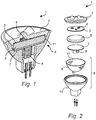
- Fig. 1 illustrates a lighting device 1 according to a first exemplary embodiment of the present invention.
- the lighting device 1 comprises an exit window 2 and a light source substrate 3 arranged to carry at least one solid-state light source 4.
- the solid-state light source 4 is arranged to emit light through the exit window 2.
- the lighting device 1 has a biasing element 5 which is pressing the light source substrate 3 into thermal contact with the exit window 2, and a funnel-shaped body 6 surrounding the light source 4 and reflecting light emitted from the light source 4 towards the exit window 2.
- the exit window 2 has a recess 12 in the surface facing the light source substrate 3 which recess is shaped to receive the light source 4 when the light source substrate 3 and the exit window 2 bear against each other.
- the substrate 3 and the exit window 2 make contact across a larger area, i.e. most of the area surrounding the light sources 3.
- the lighting device 1 is equipped with a plurality of light sources 4, it may be equipped with a recess 12 for every light source 4. It could naturally also be possible to provide a recess 12 which can receive a plurality of light sources 4.
- Some of the light emitted by the light source 4 is reflected towards the exit window 2 by means of a reflective surface 11 provided on the inside surface of the funnel-shaped body 6.
- the biasing element 5 will improve the heat transfer between the light source substrate 3 and the exit window 2 and thus facilitate the heat transfer from the light source 4 towards and through the front exit window 2 to the ambient.
- the lighting device 1 further comprises a driver substrate 7 which carries a light source driver circuitry 8.
- the biasing element 5 is sandwiched between the light source substrate 3 and the driver substrate 7, thereby pressing the light source substrate 3 into thermal contact with the exit window 2, as described above, and simultaneously pressing the driver substrate 7 into thermal contact with the funnel-shaped body 6. That is to say, when mounted in the lighting device 1, the biasing element 5 is in a compressed state, so as to apply a force on the two substrates 3, 7.
- the thermal contact between the driver substrate 7 and the funnel-shaped body 6 is thereby also secured and an efficient heat transfer from the light source towards and through the funnel-shaped body 6 to the ambient will thus be provided.
- the light source substrate 3 is constituted by a printed circuit board on which the light source 4 or light sources 4 are attached
- the driver substrate 7 is constituted by a printed circuit board on which the light source driver circuitry 8 (electronics) are attached.
- the funnel-shaped body 6 has at least two shoulders provided on its inner surface against which the driver substrate 7 will abut when mounted in the lighting device 1.
- the funnel-shaped body 6 is preferably made of glass. Glass is a preferred material because it is a cheap and sustainable basic material. The good properties of glass are low cost, sustainable, good optical properties, nice aesthetics, and electrical insulation function.
- the funnel-shaped body 6 has an inner and an outer glass part 9, 10.
- the glass parts 9, 10 of the funnel-shaped body 6 are preferably 0,5 mm thick and the distance between them which is preferably 1 mm.
- a drawback of glass is its thermal conductivity which is about 1 W/(m.K).
- that problem could be solved by using a thermal filler provided between the glass parts 9, 10 of the funnel-shaped body 6. This way, the thermal conductivity of the glass will be significantly improved. The result is achieved due to an improved heat transfer from the light source 2 towards and through the parts 9, 10 of the funnel-shaped body 6 to the ambient.
- the reflective surface 11 is provided on the inner surface of the inner part 9 of the funnel-shaped body 6. Further, the inner part 9 has at least two shoulders provided on its inner surface against which the driver substrate 7 will abut when mounted in the lighting device 1 according to the second exemplary embodiment.
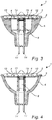
- Fig. 3 illustrates a lighting device 1 according to a third exemplary embodiment of the present invention.
- the lighting device 1 comprises a light source substrate 3 which is clamped between the exit window 2 and the funnel-shaped body 6. Thermal glue can also be used in order to additionally secure the light source substrate 3 between the exit window 2 and the funnel-shaped body 6.
- the light sources 4 are attached to the surface of the light source substrate 3 facing the exit window 2, and the light source driver circuitry 8 is attached to the opposite surface of the light source substrate 3.
- the recesses 12 of the exit window 2 are adapted to receive the light sources 4.
- the lighting device 1 further comprises two electrically conductive sleeves 13 which are attached to the light source substrate 3. In turn, a pin 14 is introduced in each one of the sleeves 13. The pins 14 extend outside of the funnel-shaped body 6 and will provide the light source substrate 3 with power via the sleeves 13 when the lighting device 1 is in use.
- the lighting device 1 comprises a light source substrate 3 which is attached to the exit window 2 by means of thermal glue.
- the light sources 4 are attached to the surface of the light source substrate 3 facing the exit window 2, and the light source driver circuitry 8 is attached to the opposite surface of the light source substrate 3.
- the recesses 12 of the exit window 2 are adapted to receive the light sources 4.
- the lighting device 1 further comprises two electrically conductive sleeves 13 which are attached to the light source substrate 3.
- a pin 14 is introduced in each one of the sleeves 13. The pins 14 extend outside of the funnel-shaped body 6 and will provide the light source substrate 3 with power via the sleeves 13 when the lighting device 1 is in use.
- the funnel-shaped body 6 is provided as a first element and constitutes the bottom section of the lighting device 1.
- Two electrically conductive connectors, e.g. pins as illustrated in figure 4 , for supplying electricity to the lighting device 1 are attached to the bottom part of the funnel-shaped body 6.
- the driver substrate 7 is placed within the funnel-shaped body 6 in contact with the connectors, e.g. by means of sleeves as illustrated in figure 4 .
- the biasing element 5 is placed on top of the driver substrate 7, and on top of the biasing element 5, the light source substrate 3 is provided.
- the exit window 2 is attached to the funnel-shaped body 6 as a top section of the lighting device 1.
- the exit window 2 When the exit window 2 is attached to the funnel-shaped body 6, it will press down on the parts placed within the funnel-shaped body 6, thus placing the biasing element 5 in a compressed state.
- the result of the biasing element 5 being in a compressed state is that the light source substrate 3 is being pressed into thermal contact with the exit window 2 simultaneously as the driver substrate 7 is being pressed into thermal contact with the funnel-shaped body 6. Thereby, the heat transfer between the main elements of the lighting device 1 is secured and the temperature of the same can be kept to a minimum.
- the exit window 2 can be attached to the funnel-shaped body 6 by, for example, a thermal glue. Another possibility is to provide the exit window 2 with an outer threading and the funnel-shaped body 6 with an inner threading and thereafter attach the exit window 2 to the funnel-shaped body 6 by screwing.
- the biasing element can be made of a number of different materials.
- the biasing element is constituted by a thermal glue arranged to thermally attach the light source substrate with the exit window, and to thermally attach driver substrate with the funnel-shaped body.
- the exit window and the funnel-shaped body are integrally formed.
- the biasing element is a resilient member which is in a compressed state, so as to apply a force on the substrate(s).
Landscapes
- Engineering & Computer Science (AREA)
- General Engineering & Computer Science (AREA)
- Microelectronics & Electronic Packaging (AREA)
- Physics & Mathematics (AREA)
- Optics & Photonics (AREA)
- Arrangement Of Elements, Cooling, Sealing, Or The Like Of Lighting Devices (AREA)
- Non-Portable Lighting Devices Or Systems Thereof (AREA)
- Fastening Of Light Sources Or Lamp Holders (AREA)
Applications Claiming Priority (2)
| Application Number | Priority Date | Filing Date | Title |
|---|---|---|---|
| US201361766265P | 2013-02-19 | 2013-02-19 | |
| PCT/IB2014/059032 WO2014128605A1 (en) | 2013-02-19 | 2014-02-17 | Lighting device with improved thermal properties |
Publications (2)
| Publication Number | Publication Date |
|---|---|
| EP2959209A1 EP2959209A1 (en) | 2015-12-30 |
| EP2959209B1 true EP2959209B1 (en) | 2018-09-12 |
Family
ID=50290217
Family Applications (1)
| Application Number | Title | Priority Date | Filing Date |
|---|---|---|---|
| EP14710984.7A Active EP2959209B1 (en) | 2013-02-19 | 2014-02-17 | Lighting device with improved thermal properties |
Country Status (8)
| Country | Link |
|---|---|
| US (1) | US10208938B2 (enExample) |
| EP (1) | EP2959209B1 (enExample) |
| JP (1) | JP6387971B2 (enExample) |
| CN (1) | CN105008788B (enExample) |
| BR (1) | BR112015019549A2 (enExample) |
| MX (1) | MX2015010534A (enExample) |
| RU (1) | RU2681952C2 (enExample) |
| WO (1) | WO2014128605A1 (enExample) |
Families Citing this family (3)
| Publication number | Priority date | Publication date | Assignee | Title |
|---|---|---|---|---|
| CN104676513A (zh) * | 2015-03-27 | 2015-06-03 | 立达信绿色照明股份有限公司 | 灯头电连接结构 |
| US10820428B2 (en) * | 2017-06-28 | 2020-10-27 | The Boeing Company | Attachment apparatus and methods for use |
| EP4187145A1 (en) | 2021-11-25 | 2023-05-31 | Yuri Borisovich Sokolov | Led cluster |
Family Cites Families (40)
| Publication number | Priority date | Publication date | Assignee | Title |
|---|---|---|---|---|
| US7144140B2 (en) * | 2005-02-25 | 2006-12-05 | Tsung-Ting Sun | Heat dissipating apparatus for lighting utility |
| US7758223B2 (en) * | 2005-04-08 | 2010-07-20 | Toshiba Lighting & Technology Corporation | Lamp having outer shell to radiate heat of light source |
| TWI281363B (en) * | 2005-12-14 | 2007-05-11 | Jarrer Co Ltd | Light-emitting diode work lamp |
| US7976182B2 (en) | 2007-03-21 | 2011-07-12 | International Rectifier Corporation | LED lamp assembly with temperature control and method of making the same |
| US8337048B2 (en) | 2007-10-31 | 2012-12-25 | Yu-Nung Shen | Light source package having a six sided light emitting die supported by electrodes |
| TWM336390U (en) * | 2008-01-28 | 2008-07-11 | Neng Tyi Prec Ind Co Ltd | LED lamp |
| TW200940881A (en) * | 2008-03-18 | 2009-10-01 | Pan Jit Internat Inc | LED lamp with thermal convection and thermal conduction heat dissipating effect, and heat dissipation module thereof |
| CN102077011B (zh) | 2008-06-26 | 2014-12-10 | 奥斯兰姆施尔凡尼亚公司 | 具有远程磷光体涂层的led灯和制造该灯的方法 |
| JP4447644B2 (ja) * | 2008-07-15 | 2010-04-07 | シーシーエス株式会社 | 光照射装置 |
| CN101672432B (zh) * | 2008-09-11 | 2012-11-21 | 富准精密工业(深圳)有限公司 | 发光二极管灯具 |
| JP5701768B2 (ja) | 2008-11-18 | 2015-04-15 | リングデール インコーポレーテッド | ヒートシンクと熱伝導性ガラス製カバーを備えたled光源アセンブリ |
| US8684563B2 (en) * | 2008-12-30 | 2014-04-01 | Kitagawa Holdings, Llc | Heat dissipating structure of LED lamp cup made of porous material |
| CN102282412B (zh) * | 2009-01-20 | 2014-05-14 | 松下电器产业株式会社 | 照明装置 |
| DE102009035370A1 (de) | 2009-07-30 | 2011-02-03 | Osram Gesellschaft mit beschränkter Haftung | Lampe |
| JP2013506251A (ja) * | 2009-09-25 | 2013-02-21 | オスラム オプト セミコンダクターズ ゲゼルシャフト ミット ベシュレンクテル ハフツング | 半導体照明装置 |
| TWI391609B (zh) * | 2009-09-28 | 2013-04-01 | Yu Nung Shen | Light emitting diode lighting device |
| WO2011050256A1 (en) * | 2009-10-22 | 2011-04-28 | Thermal Solution Resources, Llc | Overmolded led light assembly and method of manufacture |
| CN101706049B (zh) | 2009-10-30 | 2012-12-26 | 王景慧 | 一种改进散热结构的led灯 |
| CN102072476A (zh) * | 2009-11-20 | 2011-05-25 | 富准精密工业(深圳)有限公司 | 发光二极管灯具 |
| CN102109103B (zh) * | 2009-12-28 | 2013-02-27 | 旭丽电子(广州)有限公司 | 灯具及其灯座模块 |
| EP2578921A1 (en) * | 2010-06-02 | 2013-04-10 | Panasonic Corporation | Lamp and lighting device |
| KR101285889B1 (ko) * | 2010-06-23 | 2013-07-11 | 엘지전자 주식회사 | Led 조명기구 |
| KR101349841B1 (ko) * | 2010-06-24 | 2014-01-09 | 엘지전자 주식회사 | Led 조명기구 |
| KR101057064B1 (ko) * | 2010-06-30 | 2011-08-16 | 엘지전자 주식회사 | 엘이디 조명장치 및 그 제조방법 |
| CN101963295A (zh) * | 2010-07-07 | 2011-02-02 | 杨东佐 | Led集成结构及制造方法、灯、显示屏、背光装置、投影装置、成型塑胶件的注塑模 |
| JP5523228B2 (ja) * | 2010-07-08 | 2014-06-18 | キヤノン株式会社 | 表示装置及びその製造方法 |
| CN102410447A (zh) * | 2010-09-23 | 2012-04-11 | 展晶科技(深圳)有限公司 | 灯具结构 |
| US9648673B2 (en) | 2010-11-05 | 2017-05-09 | Cree, Inc. | Lighting device with spatially segregated primary and secondary emitters |
| DE102011008474B4 (de) * | 2011-01-13 | 2012-08-09 | Dräger Medical GmbH | Operationsleuchte mit LED-Ausrichtung mittels Formschluss |
| EP2497995A1 (en) * | 2011-01-18 | 2012-09-12 | Panasonic Corporation | Light source device |
| EP3133340B1 (en) * | 2011-02-21 | 2019-05-22 | LG Innotek Co., Ltd. | Lighting module and lighting device |
| RU108693U1 (ru) * | 2011-05-03 | 2011-09-20 | Закрытое Акционерное Общество "Кб "Света-Лед" | Светодиодная лампа |
| TW201251148A (en) * | 2011-06-10 | 2012-12-16 | Pan Jit Internat Inc | Manufacturing method of LED heat conduction device |
| JP2013025935A (ja) * | 2011-07-19 | 2013-02-04 | Ichikoh Ind Ltd | 車両用灯具の半導体型光源の光源ユニット、車両用灯具 |
| KR101824038B1 (ko) * | 2011-07-22 | 2018-01-31 | 엘지이노텍 주식회사 | 디스플레이 장치 |
| JP2013093158A (ja) * | 2011-10-25 | 2013-05-16 | Toshiba Lighting & Technology Corp | 電球及び照明器具 |
| TWI435026B (zh) * | 2011-11-07 | 2014-04-21 | 訊凱國際股份有限公司 | 發光裝置及其燈具之製作方法 |
| US8801233B2 (en) * | 2011-11-30 | 2014-08-12 | Cree, Inc. | Optical arrangement for a solid-state lighting system |
| CN103174950A (zh) * | 2011-12-20 | 2013-06-26 | 富准精密工业(深圳)有限公司 | 发光二极管灯泡 |
| US9097393B2 (en) * | 2012-08-31 | 2015-08-04 | Cree, Inc. | LED based lamp assembly |
-
2014
- 2014-02-17 US US14/767,736 patent/US10208938B2/en active Active
- 2014-02-17 JP JP2015557556A patent/JP6387971B2/ja active Active
- 2014-02-17 WO PCT/IB2014/059032 patent/WO2014128605A1/en not_active Ceased
- 2014-02-17 CN CN201480009325.4A patent/CN105008788B/zh active Active
- 2014-02-17 RU RU2015139891A patent/RU2681952C2/ru active
- 2014-02-17 EP EP14710984.7A patent/EP2959209B1/en active Active
- 2014-02-17 BR BR112015019549A patent/BR112015019549A2/pt not_active Application Discontinuation
- 2014-02-17 MX MX2015010534A patent/MX2015010534A/es unknown
Non-Patent Citations (1)
| Title |
|---|
| None * |
Also Published As
| Publication number | Publication date |
|---|---|
| CN105008788B (zh) | 2019-02-19 |
| JP2016507154A (ja) | 2016-03-07 |
| RU2681952C2 (ru) | 2019-03-14 |
| EP2959209A1 (en) | 2015-12-30 |
| RU2015139891A3 (enExample) | 2018-03-01 |
| RU2015139891A (ru) | 2017-03-24 |
| BR112015019549A2 (pt) | 2017-07-18 |
| US10208938B2 (en) | 2019-02-19 |
| US20150377469A1 (en) | 2015-12-31 |
| WO2014128605A1 (en) | 2014-08-28 |
| MX2015010534A (es) | 2015-11-16 |
| JP6387971B2 (ja) | 2018-09-12 |
| CN105008788A (zh) | 2015-10-28 |
Similar Documents
| Publication | Publication Date | Title |
|---|---|---|
| US9989195B2 (en) | Illumination device with folded light source carrier and method of assembly | |
| US9989194B2 (en) | Lighting device | |
| CN102906495B (zh) | 照明模块 | |
| CN104968992A (zh) | 平面照明设备 | |
| US8803409B1 (en) | Lamp device, light-emitting device and luminaire | |
| EP2959209B1 (en) | Lighting device with improved thermal properties | |
| JP2011258771A (ja) | Led素子の放熱構造 | |
| JP4812828B2 (ja) | Led照明装置 | |
| TWI519735B (zh) | 具散熱結構之led燈具 | |
| WO2012127923A1 (ja) | 照明装置、およびそれを備えた照明機器 | |
| JP6304946B2 (ja) | 照明ランプ、照明装置及び照明ランプの製造方法 | |
| JP6173790B2 (ja) | 電球型照明装置 | |
| JP6141060B2 (ja) | 照明ランプ及び照明器具 | |
| CN204611393U (zh) | 灯装置及照明装置 | |
| JP5620595B2 (ja) | 電球型の照明装置 | |
| JP5468662B2 (ja) | 電球型の照明装置 | |
| JP6469402B2 (ja) | ライト部材 | |
| CN105849462A (zh) | 散热装置和照明设备 | |
| CN111713183A (zh) | 包括用于发光元件的衬底的照明装置 | |
| JP2015109253A (ja) | 光源ユニット及び光源装置 |
Legal Events
| Date | Code | Title | Description |
|---|---|---|---|
| PUAI | Public reference made under article 153(3) epc to a published international application that has entered the european phase |
Free format text: ORIGINAL CODE: 0009012 |
|
| 17P | Request for examination filed |
Effective date: 20150921 |
|
| AK | Designated contracting states |
Kind code of ref document: A1 Designated state(s): AL AT BE BG CH CY CZ DE DK EE ES FI FR GB GR HR HU IE IS IT LI LT LU LV MC MK MT NL NO PL PT RO RS SE SI SK SM TR |
|
| AX | Request for extension of the european patent |
Extension state: BA ME |
|
| DAX | Request for extension of the european patent (deleted) | ||
| RAP1 | Party data changed (applicant data changed or rights of an application transferred) |
Owner name: PHILIPS LIGHTING HOLDING B.V. |
|
| STAA | Information on the status of an ep patent application or granted ep patent |
Free format text: STATUS: EXAMINATION IS IN PROGRESS |
|
| RIN1 | Information on inventor provided before grant (corrected) |
Inventor name: GIELEN, VINCENT, STEFAN, DAVID Inventor name: EGGINK, HENDRIK, JAN Inventor name: MARINUS, ANTONIUS, ADRIANUS, MARIA Inventor name: VAN DER LUBBE, MARCELLUS, JACOBUS, JOHANNES |
|
| 17Q | First examination report despatched |
Effective date: 20170719 |
|
| REG | Reference to a national code |
Ref country code: DE Ref legal event code: R079 Ref document number: 602014032220 Country of ref document: DE Free format text: PREVIOUS MAIN CLASS: F21K0099000000 Ipc: F21K0009233000 |
|
| GRAP | Despatch of communication of intention to grant a patent |
Free format text: ORIGINAL CODE: EPIDOSNIGR1 |
|
| STAA | Information on the status of an ep patent application or granted ep patent |
Free format text: STATUS: GRANT OF PATENT IS INTENDED |
|
| RIC1 | Information provided on ipc code assigned before grant |
Ipc: F21V 29/70 20150101ALN20180316BHEP Ipc: F21K 9/238 20160101ALI20180316BHEP Ipc: F21V 29/502 20150101ALI20180316BHEP Ipc: F21V 23/00 20150101ALN20180316BHEP Ipc: F21V 5/04 20060101ALN20180316BHEP Ipc: F21K 9/233 20160101AFI20180316BHEP Ipc: F21Y 115/10 20160101ALN20180316BHEP |
|
| INTG | Intention to grant announced |
Effective date: 20180420 |
|
| GRAS | Grant fee paid |
Free format text: ORIGINAL CODE: EPIDOSNIGR3 |
|
| GRAA | (expected) grant |
Free format text: ORIGINAL CODE: 0009210 |
|
| STAA | Information on the status of an ep patent application or granted ep patent |
Free format text: STATUS: THE PATENT HAS BEEN GRANTED |
|
| AK | Designated contracting states |
Kind code of ref document: B1 Designated state(s): AL AT BE BG CH CY CZ DE DK EE ES FI FR GB GR HR HU IE IS IT LI LT LU LV MC MK MT NL NO PL PT RO RS SE SI SK SM TR |
|
| REG | Reference to a national code |
Ref country code: GB Ref legal event code: FG4D |
|
| REG | Reference to a national code |
Ref country code: CH Ref legal event code: EP |
|
| REG | Reference to a national code |
Ref country code: IE Ref legal event code: FG4D |
|
| REG | Reference to a national code |
Ref country code: DE Ref legal event code: R096 Ref document number: 602014032220 Country of ref document: DE |
|
| REG | Reference to a national code |
Ref country code: AT Ref legal event code: REF Ref document number: 1041015 Country of ref document: AT Kind code of ref document: T Effective date: 20181015 |
|
| RAP2 | Party data changed (patent owner data changed or rights of a patent transferred) |
Owner name: PHILIPS LIGHTING HOLDING B.V. |
|
| REG | Reference to a national code |
Ref country code: NL Ref legal event code: MP Effective date: 20180912 |
|
| REG | Reference to a national code |
Ref country code: LT Ref legal event code: MG4D |
|
| PG25 | Lapsed in a contracting state [announced via postgrant information from national office to epo] |
Ref country code: BG Free format text: LAPSE BECAUSE OF FAILURE TO SUBMIT A TRANSLATION OF THE DESCRIPTION OR TO PAY THE FEE WITHIN THE PRESCRIBED TIME-LIMIT Effective date: 20181212 Ref country code: RS Free format text: LAPSE BECAUSE OF FAILURE TO SUBMIT A TRANSLATION OF THE DESCRIPTION OR TO PAY THE FEE WITHIN THE PRESCRIBED TIME-LIMIT Effective date: 20180912 Ref country code: GR Free format text: LAPSE BECAUSE OF FAILURE TO SUBMIT A TRANSLATION OF THE DESCRIPTION OR TO PAY THE FEE WITHIN THE PRESCRIBED TIME-LIMIT Effective date: 20181213 Ref country code: NO Free format text: LAPSE BECAUSE OF FAILURE TO SUBMIT A TRANSLATION OF THE DESCRIPTION OR TO PAY THE FEE WITHIN THE PRESCRIBED TIME-LIMIT Effective date: 20181212 Ref country code: SE Free format text: LAPSE BECAUSE OF FAILURE TO SUBMIT A TRANSLATION OF THE DESCRIPTION OR TO PAY THE FEE WITHIN THE PRESCRIBED TIME-LIMIT Effective date: 20180912 Ref country code: FI Free format text: LAPSE BECAUSE OF FAILURE TO SUBMIT A TRANSLATION OF THE DESCRIPTION OR TO PAY THE FEE WITHIN THE PRESCRIBED TIME-LIMIT Effective date: 20180912 Ref country code: LT Free format text: LAPSE BECAUSE OF FAILURE TO SUBMIT A TRANSLATION OF THE DESCRIPTION OR TO PAY THE FEE WITHIN THE PRESCRIBED TIME-LIMIT Effective date: 20180912 |
|
| PG25 | Lapsed in a contracting state [announced via postgrant information from national office to epo] |
Ref country code: LV Free format text: LAPSE BECAUSE OF FAILURE TO SUBMIT A TRANSLATION OF THE DESCRIPTION OR TO PAY THE FEE WITHIN THE PRESCRIBED TIME-LIMIT Effective date: 20180912 Ref country code: AL Free format text: LAPSE BECAUSE OF FAILURE TO SUBMIT A TRANSLATION OF THE DESCRIPTION OR TO PAY THE FEE WITHIN THE PRESCRIBED TIME-LIMIT Effective date: 20180912 Ref country code: HR Free format text: LAPSE BECAUSE OF FAILURE TO SUBMIT A TRANSLATION OF THE DESCRIPTION OR TO PAY THE FEE WITHIN THE PRESCRIBED TIME-LIMIT Effective date: 20180912 |
|
| RAP2 | Party data changed (patent owner data changed or rights of a patent transferred) |
Owner name: SIGNIFY HOLDING B.V. |
|
| REG | Reference to a national code |
Ref country code: AT Ref legal event code: MK05 Ref document number: 1041015 Country of ref document: AT Kind code of ref document: T Effective date: 20180912 |
|
| PG25 | Lapsed in a contracting state [announced via postgrant information from national office to epo] |
Ref country code: EE Free format text: LAPSE BECAUSE OF FAILURE TO SUBMIT A TRANSLATION OF THE DESCRIPTION OR TO PAY THE FEE WITHIN THE PRESCRIBED TIME-LIMIT Effective date: 20180912 Ref country code: PL Free format text: LAPSE BECAUSE OF FAILURE TO SUBMIT A TRANSLATION OF THE DESCRIPTION OR TO PAY THE FEE WITHIN THE PRESCRIBED TIME-LIMIT Effective date: 20180912 Ref country code: IT Free format text: LAPSE BECAUSE OF FAILURE TO SUBMIT A TRANSLATION OF THE DESCRIPTION OR TO PAY THE FEE WITHIN THE PRESCRIBED TIME-LIMIT Effective date: 20180912 Ref country code: RO Free format text: LAPSE BECAUSE OF FAILURE TO SUBMIT A TRANSLATION OF THE DESCRIPTION OR TO PAY THE FEE WITHIN THE PRESCRIBED TIME-LIMIT Effective date: 20180912 Ref country code: NL Free format text: LAPSE BECAUSE OF FAILURE TO SUBMIT A TRANSLATION OF THE DESCRIPTION OR TO PAY THE FEE WITHIN THE PRESCRIBED TIME-LIMIT Effective date: 20180912 Ref country code: CZ Free format text: LAPSE BECAUSE OF FAILURE TO SUBMIT A TRANSLATION OF THE DESCRIPTION OR TO PAY THE FEE WITHIN THE PRESCRIBED TIME-LIMIT Effective date: 20180912 Ref country code: ES Free format text: LAPSE BECAUSE OF FAILURE TO SUBMIT A TRANSLATION OF THE DESCRIPTION OR TO PAY THE FEE WITHIN THE PRESCRIBED TIME-LIMIT Effective date: 20180912 Ref country code: IS Free format text: LAPSE BECAUSE OF FAILURE TO SUBMIT A TRANSLATION OF THE DESCRIPTION OR TO PAY THE FEE WITHIN THE PRESCRIBED TIME-LIMIT Effective date: 20190112 Ref country code: AT Free format text: LAPSE BECAUSE OF FAILURE TO SUBMIT A TRANSLATION OF THE DESCRIPTION OR TO PAY THE FEE WITHIN THE PRESCRIBED TIME-LIMIT Effective date: 20180912 |
|
| PG25 | Lapsed in a contracting state [announced via postgrant information from national office to epo] |
Ref country code: SK Free format text: LAPSE BECAUSE OF FAILURE TO SUBMIT A TRANSLATION OF THE DESCRIPTION OR TO PAY THE FEE WITHIN THE PRESCRIBED TIME-LIMIT Effective date: 20180912 Ref country code: SM Free format text: LAPSE BECAUSE OF FAILURE TO SUBMIT A TRANSLATION OF THE DESCRIPTION OR TO PAY THE FEE WITHIN THE PRESCRIBED TIME-LIMIT Effective date: 20180912 Ref country code: PT Free format text: LAPSE BECAUSE OF FAILURE TO SUBMIT A TRANSLATION OF THE DESCRIPTION OR TO PAY THE FEE WITHIN THE PRESCRIBED TIME-LIMIT Effective date: 20190112 |
|
| REG | Reference to a national code |
Ref country code: DE Ref legal event code: R097 Ref document number: 602014032220 Country of ref document: DE |
|
| PLBE | No opposition filed within time limit |
Free format text: ORIGINAL CODE: 0009261 |
|
| STAA | Information on the status of an ep patent application or granted ep patent |
Free format text: STATUS: NO OPPOSITION FILED WITHIN TIME LIMIT |
|
| PG25 | Lapsed in a contracting state [announced via postgrant information from national office to epo] |
Ref country code: DK Free format text: LAPSE BECAUSE OF FAILURE TO SUBMIT A TRANSLATION OF THE DESCRIPTION OR TO PAY THE FEE WITHIN THE PRESCRIBED TIME-LIMIT Effective date: 20180912 |
|
| 26N | No opposition filed |
Effective date: 20190613 |
|
| PG25 | Lapsed in a contracting state [announced via postgrant information from national office to epo] |
Ref country code: SI Free format text: LAPSE BECAUSE OF FAILURE TO SUBMIT A TRANSLATION OF THE DESCRIPTION OR TO PAY THE FEE WITHIN THE PRESCRIBED TIME-LIMIT Effective date: 20180912 |
|
| REG | Reference to a national code |
Ref country code: CH Ref legal event code: PL |
|
| PG25 | Lapsed in a contracting state [announced via postgrant information from national office to epo] |
Ref country code: LU Free format text: LAPSE BECAUSE OF NON-PAYMENT OF DUE FEES Effective date: 20190217 Ref country code: MC Free format text: LAPSE BECAUSE OF FAILURE TO SUBMIT A TRANSLATION OF THE DESCRIPTION OR TO PAY THE FEE WITHIN THE PRESCRIBED TIME-LIMIT Effective date: 20180912 |
|
| REG | Reference to a national code |
Ref country code: BE Ref legal event code: MM Effective date: 20190228 |
|
| REG | Reference to a national code |
Ref country code: IE Ref legal event code: MM4A |
|
| PG25 | Lapsed in a contracting state [announced via postgrant information from national office to epo] |
Ref country code: LI Free format text: LAPSE BECAUSE OF NON-PAYMENT OF DUE FEES Effective date: 20190228 Ref country code: CH Free format text: LAPSE BECAUSE OF NON-PAYMENT OF DUE FEES Effective date: 20190228 |
|
| PG25 | Lapsed in a contracting state [announced via postgrant information from national office to epo] |
Ref country code: IE Free format text: LAPSE BECAUSE OF NON-PAYMENT OF DUE FEES Effective date: 20190217 |
|
| PG25 | Lapsed in a contracting state [announced via postgrant information from national office to epo] |
Ref country code: BE Free format text: LAPSE BECAUSE OF NON-PAYMENT OF DUE FEES Effective date: 20190228 |
|
| PG25 | Lapsed in a contracting state [announced via postgrant information from national office to epo] |
Ref country code: TR Free format text: LAPSE BECAUSE OF FAILURE TO SUBMIT A TRANSLATION OF THE DESCRIPTION OR TO PAY THE FEE WITHIN THE PRESCRIBED TIME-LIMIT Effective date: 20180912 |
|
| PG25 | Lapsed in a contracting state [announced via postgrant information from national office to epo] |
Ref country code: MT Free format text: LAPSE BECAUSE OF NON-PAYMENT OF DUE FEES Effective date: 20190217 |
|
| REG | Reference to a national code |
Ref country code: DE Ref legal event code: R081 Ref document number: 602014032220 Country of ref document: DE Owner name: SIGNIFY HOLDING B.V., NL Free format text: FORMER OWNER: PHILIPS LIGHTING HOLDING B.V., EINDHOVEN, NL |
|
| PG25 | Lapsed in a contracting state [announced via postgrant information from national office to epo] |
Ref country code: CY Free format text: LAPSE BECAUSE OF FAILURE TO SUBMIT A TRANSLATION OF THE DESCRIPTION OR TO PAY THE FEE WITHIN THE PRESCRIBED TIME-LIMIT Effective date: 20180912 |
|
| PG25 | Lapsed in a contracting state [announced via postgrant information from national office to epo] |
Ref country code: HU Free format text: LAPSE BECAUSE OF FAILURE TO SUBMIT A TRANSLATION OF THE DESCRIPTION OR TO PAY THE FEE WITHIN THE PRESCRIBED TIME-LIMIT; INVALID AB INITIO Effective date: 20140217 |
|
| PG25 | Lapsed in a contracting state [announced via postgrant information from national office to epo] |
Ref country code: MK Free format text: LAPSE BECAUSE OF FAILURE TO SUBMIT A TRANSLATION OF THE DESCRIPTION OR TO PAY THE FEE WITHIN THE PRESCRIBED TIME-LIMIT Effective date: 20180912 |
|
| P01 | Opt-out of the competence of the unified patent court (upc) registered |
Effective date: 20230421 |
|
| PGFP | Annual fee paid to national office [announced via postgrant information from national office to epo] |
Ref country code: FR Payment date: 20250224 Year of fee payment: 12 |
|
| PGFP | Annual fee paid to national office [announced via postgrant information from national office to epo] |
Ref country code: GB Payment date: 20250218 Year of fee payment: 12 |
|
| PGFP | Annual fee paid to national office [announced via postgrant information from national office to epo] |
Ref country code: DE Payment date: 20250428 Year of fee payment: 12 |