EP2957680A1 - Vorrichtung und verfahren zur steuerung einer arbeitsmaschine für nutzfahrzeuge - Google Patents
Vorrichtung und verfahren zur steuerung einer arbeitsmaschine für nutzfahrzeuge Download PDFInfo
- Publication number
- EP2957680A1 EP2957680A1 EP14752054.8A EP14752054A EP2957680A1 EP 2957680 A1 EP2957680 A1 EP 2957680A1 EP 14752054 A EP14752054 A EP 14752054A EP 2957680 A1 EP2957680 A1 EP 2957680A1
- Authority
- EP
- European Patent Office
- Prior art keywords
- work machine
- speed
- work
- time point
- work vehicle
- Prior art date
- Legal status (The legal status is an assumption and is not a legal conclusion. Google has not performed a legal analysis and makes no representation as to the accuracy of the status listed.)
- Granted
Links
Images




Classifications
-
- E—FIXED CONSTRUCTIONS
- E02—HYDRAULIC ENGINEERING; FOUNDATIONS; SOIL SHIFTING
- E02F—DREDGING; SOIL-SHIFTING
- E02F9/00—Component parts of dredgers or soil-shifting machines, not restricted to one of the kinds covered by groups E02F3/00 - E02F7/00
- E02F9/20—Drives; Control devices
- E02F9/2025—Particular purposes of control systems not otherwise provided for
- E02F9/2029—Controlling the position of implements in function of its load, e.g. modifying the attitude of implements in accordance to vehicle speed
-
- E—FIXED CONSTRUCTIONS
- E02—HYDRAULIC ENGINEERING; FOUNDATIONS; SOIL SHIFTING
- E02F—DREDGING; SOIL-SHIFTING
- E02F3/00—Dredgers; Soil-shifting machines
- E02F3/04—Dredgers; Soil-shifting machines mechanically-driven
- E02F3/28—Dredgers; Soil-shifting machines mechanically-driven with digging tools mounted on a dipper- or bucket-arm, i.e. there is either one arm or a pair of arms, e.g. dippers, buckets
- E02F3/36—Component parts
- E02F3/42—Drives for dippers, buckets, dipper-arms or bucket-arms
- E02F3/43—Control of dipper or bucket position; Control of sequence of drive operations
-
- E—FIXED CONSTRUCTIONS
- E02—HYDRAULIC ENGINEERING; FOUNDATIONS; SOIL SHIFTING
- E02F—DREDGING; SOIL-SHIFTING
- E02F3/00—Dredgers; Soil-shifting machines
- E02F3/04—Dredgers; Soil-shifting machines mechanically-driven
- E02F3/28—Dredgers; Soil-shifting machines mechanically-driven with digging tools mounted on a dipper- or bucket-arm, i.e. there is either one arm or a pair of arms, e.g. dippers, buckets
- E02F3/36—Component parts
- E02F3/42—Drives for dippers, buckets, dipper-arms or bucket-arms
- E02F3/43—Control of dipper or bucket position; Control of sequence of drive operations
- E02F3/431—Control of dipper or bucket position; Control of sequence of drive operations for bucket-arms, front-end loaders, dumpers or the like
- E02F3/432—Control of dipper or bucket position; Control of sequence of drive operations for bucket-arms, front-end loaders, dumpers or the like for keeping the bucket in a predetermined position or attitude
-
- E—FIXED CONSTRUCTIONS
- E02—HYDRAULIC ENGINEERING; FOUNDATIONS; SOIL SHIFTING
- E02F—DREDGING; SOIL-SHIFTING
- E02F9/00—Component parts of dredgers or soil-shifting machines, not restricted to one of the kinds covered by groups E02F3/00 - E02F7/00
- E02F9/20—Drives; Control devices
-
- E—FIXED CONSTRUCTIONS
- E02—HYDRAULIC ENGINEERING; FOUNDATIONS; SOIL SHIFTING
- E02F—DREDGING; SOIL-SHIFTING
- E02F9/00—Component parts of dredgers or soil-shifting machines, not restricted to one of the kinds covered by groups E02F3/00 - E02F7/00
- E02F9/20—Drives; Control devices
- E02F9/22—Hydraulic or pneumatic drives
- E02F9/2253—Controlling the travelling speed of vehicles, e.g. adjusting travelling speed according to implement loads, control of hydrostatic transmission
-
- G—PHYSICS
- G05—CONTROLLING; REGULATING
- G05B—CONTROL OR REGULATING SYSTEMS IN GENERAL; FUNCTIONAL ELEMENTS OF SUCH SYSTEMS; MONITORING OR TESTING ARRANGEMENTS FOR SUCH SYSTEMS OR ELEMENTS
- G05B2219/00—Program-control systems
- G05B2219/30—Nc systems
- G05B2219/45—Nc applications
- G05B2219/45012—Excavator
Definitions
- the present disclosure relates to an apparatus and a method of controlling a work machine of a work vehicle for construction or civil engineering.
- a construction machine (construction vehicle) is used for civil-engineering work or construction work, and requires large power for an operation, so that a vehicle using hydraulic pressure is used.
- the kind of hydraulic work vehicle includes a wheel loader, an excavator, a grader, a crane, a conveying machine, and the like.
- the wheel loader is a work vehicle used for digging up and moving earth and sand, aggregate, and the like in a civil-engineering work field.
- the wheel loader is dedicated equipment for repeatedly performing an operation of putting a workpiece into a front work machine (for example, a bucket of the wheel loader) according to an operation of a joystick by an operator while moving toward the workpiece (for example, earth and sand), moving to a truck or a target location, and dumping the workpiece of the work machine to a loading location.
- FIG. 1 is a diagram illustrating a wheel loader in the related art.
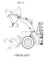
- FIG. 2 is a diagram illustrating an operation range of a boom and a bucket of a general wheel loader.
- FIG. 2 illustrates a case where a boom 1 is at a raised position and a floated position, and a bucket 2 of the wheel loader is at a crowd position (that is, the bucket has an angle b in FIG. 2 ) and a dump position (that is, the bucket has an angle a in FIG. 2 ) at each position of the boom 1.
- the boom 1 and the bucket 2 of the wheel loader are operated through a joystick of a main control valve (MCV), and further, a driver may move the wheel loader forwardly and backwardly by using a travelling device of the wheel loader during the operation.
- MCV main control valve
- the driver moves the wheel loader forwardly by using the travelling device, and raises and floats the boom 1 of the wheel loader and/or crowds and dumps the bucket 2 by operating the joystick.
- the wheel loader changes a travelling direction from forward to backward or from backward to forward during the operation, and simultaneously operates the work machine (for example, the boom and the bucket of the wheel loader).
- a work vehicle for example, a wheel loader
- a front work machine for example, a boom and a bucket of a wheel loader
- an impact of the front work machine for example, a conversion of an operation of the boom or the bucket, or a stop of an operation of the boom or the bucket
- the impact of the front work machine may break a balance of the travelling vehicle and degrade work efficiency.
- a technical object of the present disclosure to be solved is to adaptively and differently control the amount of impact and a control property of a front work machine according to a speed of a work vehicle when the work vehicle is travelling.
- an exemplary embodiment of the present disclosure provides an apparatus for controlling a work machine of a work vehicle, comprising: a speed sensor configured to measure a speed of a work vehicle; an electric main controller valve (EMCV) configured to convert an input signal of a joystick into an output current for controlling a proportional valve (P/V) for operating a work machine (for example, a boom and a bucket); and control unit configured to receive information on a speed of the work vehicle from the speed sensor, control an output current from the EMCV according to the speed of the work vehicle, and control an impact applied to the work machine while travelling.
- EMCV electric main controller valve
- P/V proportional valve
- the apparatus for controlling a work machine of a work vehicle measures a speed of a work vehicle, converts an input signal of a joystick into an output current for controlling a proportional valve (P/V) for operating a work machine (for example, a boom and a bucket), compares the speed of the work vehicle with a reference speed, and advances or delays an end time point of the work machine, thereby controlling an impact applied to the work vehicle.
- P/V proportional valve
- a work vehicle when a work vehicle performs an operation while travelling, it is possible to linearly change an end time point of a joystick by considering a speed of the work vehicle. That is, according to the exemplary embodiments of the present disclosure, it is possible to accurately and rapidly control a work machine when a work vehicle performs an operation while travelling at a low speed, but delay an operation of the work machine when the work vehicle performs an operation while travelling at a high speed, thereby decreasing the amount of impact applied to the work vehicle.
- module and unit suffixes for components used in the present specification are given or mixed and used by considering only easiness in preparing a specification and do not have a meaning or role distinguished from each other in themselves.
- first and second used in the present specification may be used for describing various constituent elements, but the constituent elements should not be limited by the terms. The terms are used only to discriminate one constituent element from another constituent element.
- first constituent element may be referred to as the second component and similarly, the second constituent element is also referred to as the first constituent element.
- a term "and/or" described in the present disclosure includes a combination of a plurality of related items or any one items among the plurality of related items.
- a basic concept of an exemplary embodiment suggested in the present disclosure is to adjust an output current curve according to an input of an electronic joystick operating a work machine according to a speed of a work machine (for example, a wheel loader), and when the work vehicle is travelling at a predetermined reference speed or higher, to soften a reaction of the work machine according to the input of the joystick to decrease an impact to the travelling work vehicle.
- a work machine for example, a wheel loader
- FIG. 3 is a block diagram illustrating an example of an apparatus for controlling a work machine of a work vehicle according to an exemplary embodiment of the present disclosure.
- an apparatus 300 for controlling a work machine of a work vehicle includes: a speed sensor 310 measuring a speed of the work machine; an electric main controller valve (EMCV) 320 for converting an input signal of a joystick into an output current for controlling a proportional valve (P/V) for operating the work machine (for example, a boom and a bucket); and a control unit 330 receiving information on a speed of the work vehicle from a speed sensor 310, controlling the output current from the EMCV 320 according to the speed of the work vehicle, and controlling an impact of the work machine while the work vehicle is travelling.
- EMCV electric main controller valve
- P/V proportional valve
- the EMCV 320 is a main controller valve (MCV) receiving an electronic joystick signal and controlling a current of the P/V.
- MCV main controller valve
- the MCV controls an operation of the work machine through a supply of hydraulic pressure to a cylinder or a work machine.
- the MCV may include a boom control valve and a bucket control valve, and in the boom control valve and the bucket control valve, an open degree of a valve is controlled according to a current applied from the control unit. Further, the boom control valve controls raising and floating operations of the boom, and the bucket control valve controls crowd and dump operations of the bucket.
- the EMCV 320 may include a boom joystick 321 and a bucket joystick 322, and the boom joystick 321 is an input device for the raising and floating operations of the boom, and the bucket joystick 322 is an input device for the dump and crowd operation of the bucket.
- FIG. 4 is a circuit diagram illustrating an example of the apparatus for controlling a work machine of a work vehicle according to the exemplary embodiment of the present disclosure.
- the control unit is a vehicle control unit (VCU).
- VCU vehicle control unit
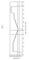
- FIG. 5 is a graph illustrating an example of an output current according to an input of the joystick of the EMCV according to the exemplary embodiment of the present disclosure.
- FIG. 5 illustrates a corresponding current value according to a position of the joystick of the EMCV 320.
- a degree of opening of the P/V is adjusted according to X-axis input values of the joysticks 321 and 322.
- Input values of 31 to 32 of the joysticks 321 and 322 correspond to neutral values of the joysticks 321 and 322. That is, it can be recognized that an output current value is changed according to an operation of the joystick in up and down directions based on the input values of 31 to 32 of the joysticks 321 and 322.
- a point, at which the input values of the joysticks 321 and 322 are 30, is a position at which the joysticks return to the neutral value (that is, 31 to 32 in FIG. 5 ).
- the output current values of the joysticks 321 and 322 are 320 mA.
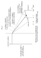
- FIG. 6 is a graph illustrating an example of a control of the output current of the apparatus for controlling a work machine according to the exemplary embodiment of the present disclosure.
- FIG. 6 is a graph illustrating a time point, at which the joystick returns to the neutral value, in FIG. 5 in detail.
- a finish point of the joystick is controlled to be linearly changed considering a speed of the work vehicle, so that when the work vehicle is travelling at a low speed, the apparatus accurately and delicately controls the front work machine (the boom and the bucket), but when the work vehicle is travelling at a high speed, the apparatus delays a time point, at which the operation of the front work machine is stopped, thereby decreasing the amount of impact applied to the work vehicle due to a sudden stop of the work machine.
- This may also be performed by using an acceleration value of the work vehicle. When a speed value is used, the amount of impact may be simply decreased, but when an acceleration value is used, a rollover probability of the work vehicle may be reduced.
- a driver operates the front work machine (for example, the boom and the bucket) and performs an earth and sand loading operation while driving the work vehicle (for example, the wheel loader).
- the front work machine for example, the boom and the bucket
- the work vehicle for example, the wheel loader
- the control unit 330 of the apparatus 300 for controlling a work machine of a work vehicle receives information on a speed of the work vehicle from the speed sensor 310, and determines whether the speed of the work vehicle corresponds to a time point (that is, point "A" in FIG. 6 ), at which an impact to the work machine is relieved. That is, the control unit 330 determines whether a travelling speed of the work vehicle is a predetermined speed (so called a threshold speed, for example, 35 km/h). When it is determined that the travelling speed of the work vehicle is equal to or larger than the threshold speed, it is determined whether the joysticks 321 and 322 are currently at the time point (for example, point "A in FIG.
- the control unit 330 delays an output current according to an input of the currently operated joystick as illustrated in FIG. 6 .
- the control unit 330 delays an operation of the P/V actually operating the work machine by delaying the output current according to the input of the joysticks 321 and 322 as illustrated in FIG. 6 .
- the control unit 330 selects so called a "work machine control curve 65 (that is, a control end point change curve of the work machine)" capable of controlling the output current of the joystick according to the travelling speed of the work vehicle.
- a P/V control current curve 61 of the boom that is, the work machine of the wheel loader
- a P/V control of the boom is actually ended at a point 64 meeting the work machine control curve 65 at time point C.
- the work machine is actually stopped at time point C', at which the P/V control current curve 61 meets a minimum current value, by which the P/V on a Y-axis actually moves. That is, even though the work machine is actually stopped at time point C', the control unit 330 controls the work machine up to a time point at which the P/V control current curve 61 meets the work machine control curve 65.
- a deviation of the minimum current value, by which the P/V actually moves, may be generated for each vehicle, so that the aforementioned control is for the purpose of complementing the deviation of the minimum current value.
- the end time point of the work machine may be advanced or delayed according to the travelling speed of the work vehicle.
- a time point, at which the operation starts may be controlled by the same method as the aforementioned method.
- the control unit 330 starts the control of the P/V at a point, at which point D meets the work machine control curve when the travelling speed is large.
- FIG. 7 is a flowchart illustrating an example of a method of operating the apparatus for controlling a work machine according to an exemplary embodiment of the present disclosure.
- the control unit 330 selects so called a "work machine control curve (for example, the work machine control curve 65 of FIG. 6 ) for advancing or delaying a reaction of the work machine according to an input of the joystick (S710).
- the "work machine control curve” 65 is predetermined, and a driver may set the control curves having various inclinations.
- the control unit 330 detects a travelling speed of the work vehicle through the speed sensor 310 while the work vehicle travels and performs a specific operation (for example, an earth and sand loading operation) (S720). In this case, the control unit 330 detects whether the input of the joystick of the EMCV 320 returns to a neutral value (S730).
- a specific operation for example, an earth and sand loading operation
- control unit 330 determines that the detected travelling speed is equal to or larger than a reference speed (a predetermined speed value) (S740)
- the control unit 330 controls an end time point of the work machine (the boom and/or the bucket) to be delayed based on the "work machine control curve" selected in operation S710 (S750).
- the control unit 330 determines that the detected travelling speed is smaller than the reference speed (the predetermined speed value) (S740)
- the control unit 330 controls an end time point of the work machine (the boom and/or the bucket) to be advanced based on the "work machine control curve" selected in operation S710(S760).
- the exemplary embodiment of the present disclosure it is possible to adjust an output current curve according to the inputs of the joysticks 321 and 322 of the EMCV 320 according to a travelling speed by recognizing the travelling speed of the work vehicle. Accordingly, according to the exemplary embodiment of the present disclosure, it is possible to accurately and delicately control an operation of the work machine by making the work machine quickly react to the input of the joystick when a travelling speed is smaller than a reference speed. Further, according to the exemplary embodiment of the present disclosure, it is possible to accurately and delicately control an operation of the work machine by delaying time so that the work machine slowly reacts to the input of the joystick when a travelling speed is equal to or larger than a reference speed.
- the aforementioned method may be implemented by various means.
- the exemplary embodiments of the present disclosure will be implemented by hardware, firmware, software, or a combination thereof.
- the method according to the exemplary embodiments of the present disclosure may be implemented in one or more of application specific integrated circuits (ASICs), digital signal processors (DSPs), digital signal processing devices (DSPDs), programmable logic devices (PLDs), field programmable gate arrays (FPGAs), processors, controllers, microcontrollers, and microprocessors.
- ASICs application specific integrated circuits
- DSPs digital signal processors
- DSPDs digital signal processing devices
- PLDs programmable logic devices
- FPGAs field programmable gate arrays
- processors controllers, microcontrollers, and microprocessors.
- the method according to the exemplary embodiments of the present disclosure may be implemented by a form of a module, a procedure, a function, and the like performing the aforementioned functions or operations.
- a software code may be stored in a memory unit and driven by a processor.
- the memory unit may be positioned inside or outside the processor to transceive data with the processor by already publicly known various means.
Landscapes
- Engineering & Computer Science (AREA)
- Mining & Mineral Resources (AREA)
- Civil Engineering (AREA)
- General Engineering & Computer Science (AREA)
- Structural Engineering (AREA)
- Mechanical Engineering (AREA)
- Operation Control Of Excavators (AREA)
Applications Claiming Priority (2)
| Application Number | Priority Date | Filing Date | Title |
|---|---|---|---|
| KR1020130015264A KR102031376B1 (ko) | 2013-02-13 | 2013-02-13 | 작업용 차량의 작업기 제어 장치 및 그 방법 |
| PCT/KR2014/000982 WO2014126355A1 (ko) | 2013-02-13 | 2014-02-05 | 작업용 차량의 작업기 제어 장치 및 그 방법 |
Publications (3)
| Publication Number | Publication Date |
|---|---|
| EP2957680A1 true EP2957680A1 (de) | 2015-12-23 |
| EP2957680A4 EP2957680A4 (de) | 2017-02-08 |
| EP2957680B1 EP2957680B1 (de) | 2020-04-08 |
Family
ID=51354320
Family Applications (1)
| Application Number | Title | Priority Date | Filing Date |
|---|---|---|---|
| EP14752054.8A Active EP2957680B1 (de) | 2013-02-13 | 2014-02-05 | Vorrichtung und verfahren zur steuerung der arbeitsmaschine eines nutzfahrzeuges |
Country Status (4)
| Country | Link |
|---|---|
| US (1) | US9469968B2 (de) |
| EP (1) | EP2957680B1 (de) |
| KR (1) | KR102031376B1 (de) |
| WO (1) | WO2014126355A1 (de) |
Cited By (2)
| Publication number | Priority date | Publication date | Assignee | Title |
|---|---|---|---|---|
| WO2022008560A1 (en) * | 2020-07-07 | 2022-01-13 | Cnh Industrial Italia S.P.A. | Method for aiding the orientation and adjusting of a work tool and work vehicle for performing the method |
| IT202100007880A1 (it) * | 2021-03-30 | 2022-09-30 | Cnh Ind Italia Spa | Metodo di controllo di attuazione di un organo idraulico di un veicolo da lavoro o agricolo |
Families Citing this family (6)
| Publication number | Priority date | Publication date | Assignee | Title |
|---|---|---|---|---|
| CN107250461B (zh) * | 2016-10-28 | 2018-10-12 | 株式会社小松制作所 | 装载机械的控制系统及装载机械的控制方法 |
| CN106948406B (zh) * | 2017-02-27 | 2019-03-08 | 青岛雷沃工程机械有限公司 | 一种挖掘机快速切换挖土甩土模式的控制方法及系统 |
| ES2829278T3 (es) | 2017-09-22 | 2021-05-31 | Caterpillar Inc | Máquina con sistema de control hidráulico y método |
| JP7036606B2 (ja) * | 2018-01-31 | 2022-03-15 | 株式会社小松製作所 | 積込機械の制御装置および制御方法 |
| US20220186469A1 (en) * | 2020-12-14 | 2022-06-16 | Cnh Industrial America Llc | System and method for controlling implement operation of a work vehicle using a speed-based parameter |
| CN113513055B (zh) * | 2021-04-25 | 2023-03-21 | 潍柴动力股份有限公司 | 一种推土机的控制方法、装置及推土机 |
Family Cites Families (9)
| Publication number | Priority date | Publication date | Assignee | Title |
|---|---|---|---|---|
| KR100198058B1 (ko) | 1996-10-29 | 1999-06-15 | 토니헬샴 | 중장비의 주행 피칭 현상 완화장치 |
| US5768811A (en) * | 1997-02-19 | 1998-06-23 | Vermeer Manufacturing Company | System and process for controlling an excavation implement |
| KR100227579B1 (ko) | 1997-12-19 | 1999-11-01 | 김형벽 | 붐 실린더의 동작중 발생되는 충격을 완화하기 위한 전기 유압제어장치 |
| KR100505349B1 (ko) | 1998-05-18 | 2005-09-26 | 볼보 컨스트럭션 이키프먼트 홀딩 스웨덴 에이비 | 건설기계의 작업장치 제어방법 |
| JP3691323B2 (ja) | 2000-01-19 | 2005-09-07 | 新キャタピラー三菱株式会社 | 建設機械の油圧制御装置 |
| US7076354B2 (en) * | 2000-03-24 | 2006-07-11 | Komatsu Ltd. | Working unit control apparatus of excavating and loading machine |
| WO2006107242A1 (en) * | 2005-04-04 | 2006-10-12 | Volvo Construction Equipment Holding Sweden Ab | A method for damping relative movements occurring in a work vehicle during advance |
| KR101293314B1 (ko) | 2006-09-04 | 2013-08-05 | 두산인프라코어 주식회사 | 휠 기종 건설 기계의 주행 안정화 장치 |
| SE536152C2 (sv) * | 2011-04-07 | 2013-06-04 | Brokk Ab | Styrsystem för en fjärrstyrd arbetsmaskin utrustad med en manöverbar arm |
-
2013
- 2013-02-13 KR KR1020130015264A patent/KR102031376B1/ko active Active
-
2014
- 2014-02-05 US US14/767,474 patent/US9469968B2/en not_active Expired - Fee Related
- 2014-02-05 EP EP14752054.8A patent/EP2957680B1/de active Active
- 2014-02-05 WO PCT/KR2014/000982 patent/WO2014126355A1/ko not_active Ceased
Cited By (3)
| Publication number | Priority date | Publication date | Assignee | Title |
|---|---|---|---|---|
| WO2022008560A1 (en) * | 2020-07-07 | 2022-01-13 | Cnh Industrial Italia S.P.A. | Method for aiding the orientation and adjusting of a work tool and work vehicle for performing the method |
| IT202100007880A1 (it) * | 2021-03-30 | 2022-09-30 | Cnh Ind Italia Spa | Metodo di controllo di attuazione di un organo idraulico di un veicolo da lavoro o agricolo |
| EP4067581A1 (de) * | 2021-03-30 | 2022-10-05 | CNH Industrial Italia S.p.A. | Verfahren zur steuerung der betätigung mindestens eines hydraulischen organs eines arbeitsfahrzeugs oder landwirtschaftlichen fahrzeugs |
Also Published As
| Publication number | Publication date |
|---|---|
| KR20140102370A (ko) | 2014-08-22 |
| US9469968B2 (en) | 2016-10-18 |
| WO2014126355A1 (ko) | 2014-08-21 |
| KR102031376B1 (ko) | 2019-10-11 |
| EP2957680B1 (de) | 2020-04-08 |
| US20160002881A1 (en) | 2016-01-07 |
| EP2957680A4 (de) | 2017-02-08 |
Similar Documents
| Publication | Publication Date | Title |
|---|---|---|
| EP2957680B1 (de) | Vorrichtung und verfahren zur steuerung der arbeitsmaschine eines nutzfahrzeuges | |
| KR102314498B1 (ko) | 작업 기계 | |
| CN113423895B (zh) | 液压挖掘机 | |
| US11359349B2 (en) | Work vehicle, work management system, and work vehicle control method | |
| CN108699802B (zh) | 作业机械 | |
| US20190226179A1 (en) | Wheel loader | |
| EP2508681B1 (de) | Vorrichtung zur arretierung des kompletten vorschubs für eine radladerschaufel | |
| EP2667059A1 (de) | Radlader und verfahren zur steuerung des radladers | |
| CN103562465B (zh) | 作业车辆和作业车辆的控制方法 | |
| KR20190034648A (ko) | 작업 기계 | |
| US9014923B2 (en) | Position control apparatus and method for working machine of construction machinery | |
| KR20200028993A (ko) | 작업 기계 | |
| US9551132B2 (en) | Automatic transmission control unit for construction equipment and control method therefor | |
| EP2657492A2 (de) | Steuersystem mit niedriger leerlaufzeit für eine bauausrüstung und automatisches steuerverfahren dafür | |
| US9079578B2 (en) | Apparatus and method for controlling transmission cut-off of heavy construction equipment | |
| US9562345B2 (en) | Driving control method for construction machine | |
| EP3385456A1 (de) | Verfahren zur steuerung der durchflussmenge einer baumaschine und system zur durchführung des verfahrens | |
| KR20140080770A (ko) | 산업용 차량의 엔진 제어 방법 및 장치 | |
| KR102786354B1 (ko) | 작업 기계 | |
| KR102088067B1 (ko) | 건설기계의 테일 제어 시스템 및 그 방법 | |
| US11679682B2 (en) | Haulage vehicle | |
| US20250207353A1 (en) | Work vehicle | |
| US11808006B2 (en) | Work vehicle with automatic dump and tilt control and method for automatically controlling dump and tilt operations of work vehicle | |
| JP4593547B2 (ja) | 作業機干渉防止装置およびその制御方法 | |
| KR20130087079A (ko) | 건설기계의 디텐트 기능 자동 튜닝 시스템 |
Legal Events
| Date | Code | Title | Description |
|---|---|---|---|
| PUAI | Public reference made under article 153(3) epc to a published international application that has entered the european phase |
Free format text: ORIGINAL CODE: 0009012 |
|
| 17P | Request for examination filed |
Effective date: 20150827 |
|
| AK | Designated contracting states |
Kind code of ref document: A1 Designated state(s): AL AT BE BG CH CY CZ DE DK EE ES FI FR GB GR HR HU IE IS IT LI LT LU LV MC MK MT NL NO PL PT RO RS SE SI SK SM TR |
|
| AX | Request for extension of the european patent |
Extension state: BA ME |
|
| DAX | Request for extension of the european patent (deleted) | ||
| RIC1 | Information provided on ipc code assigned before grant |
Ipc: E02F 9/20 20060101AFI20160922BHEP Ipc: E02F 9/22 20060101ALI20160922BHEP Ipc: E02F 3/43 20060101ALI20160922BHEP |
|
| A4 | Supplementary search report drawn up and despatched |
Effective date: 20170112 |
|
| RIC1 | Information provided on ipc code assigned before grant |
Ipc: E02F 9/20 20060101AFI20170105BHEP Ipc: E02F 9/22 20060101ALI20170105BHEP Ipc: E02F 3/43 20060101ALI20170105BHEP |
|
| STAA | Information on the status of an ep patent application or granted ep patent |
Free format text: STATUS: EXAMINATION IS IN PROGRESS |
|
| 17Q | First examination report despatched |
Effective date: 20180606 |
|
| GRAP | Despatch of communication of intention to grant a patent |
Free format text: ORIGINAL CODE: EPIDOSNIGR1 |
|
| STAA | Information on the status of an ep patent application or granted ep patent |
Free format text: STATUS: GRANT OF PATENT IS INTENDED |
|
| INTG | Intention to grant announced |
Effective date: 20190830 |
|
| GRAS | Grant fee paid |
Free format text: ORIGINAL CODE: EPIDOSNIGR3 |
|
| GRAJ | Information related to disapproval of communication of intention to grant by the applicant or resumption of examination proceedings by the epo deleted |
Free format text: ORIGINAL CODE: EPIDOSDIGR1 |
|
| GRAL | Information related to payment of fee for publishing/printing deleted |
Free format text: ORIGINAL CODE: EPIDOSDIGR3 |
|
| STAA | Information on the status of an ep patent application or granted ep patent |
Free format text: STATUS: EXAMINATION IS IN PROGRESS |
|
| GRAR | Information related to intention to grant a patent recorded |
Free format text: ORIGINAL CODE: EPIDOSNIGR71 |
|
| STAA | Information on the status of an ep patent application or granted ep patent |
Free format text: STATUS: GRANT OF PATENT IS INTENDED |
|
| INTC | Intention to grant announced (deleted) | ||
| INTG | Intention to grant announced |
Effective date: 20200129 |
|
| GRAA | (expected) grant |
Free format text: ORIGINAL CODE: 0009210 |
|
| STAA | Information on the status of an ep patent application or granted ep patent |
Free format text: STATUS: THE PATENT HAS BEEN GRANTED |
|
| AK | Designated contracting states |
Kind code of ref document: B1 Designated state(s): AL AT BE BG CH CY CZ DE DK EE ES FI FR GB GR HR HU IE IS IT LI LT LU LV MC MK MT NL NO PL PT RO RS SE SI SK SM TR |
|
| REG | Reference to a national code |
Ref country code: AT Ref legal event code: REF Ref document number: 1254555 Country of ref document: AT Kind code of ref document: T Effective date: 20200415 Ref country code: CH Ref legal event code: EP |
|
| REG | Reference to a national code |
Ref country code: IE Ref legal event code: FG4D |
|
| REG | Reference to a national code |
Ref country code: DE Ref legal event code: R096 Ref document number: 602014063519 Country of ref document: DE |
|
| REG | Reference to a national code |
Ref country code: SE Ref legal event code: TRGR |
|
| REG | Reference to a national code |
Ref country code: NL Ref legal event code: MP Effective date: 20200408 |
|
| REG | Reference to a national code |
Ref country code: LT Ref legal event code: MG4D |
|
| PG25 | Lapsed in a contracting state [announced via postgrant information from national office to epo] |
Ref country code: LT Free format text: LAPSE BECAUSE OF FAILURE TO SUBMIT A TRANSLATION OF THE DESCRIPTION OR TO PAY THE FEE WITHIN THE PRESCRIBED TIME-LIMIT Effective date: 20200408 Ref country code: NL Free format text: LAPSE BECAUSE OF FAILURE TO SUBMIT A TRANSLATION OF THE DESCRIPTION OR TO PAY THE FEE WITHIN THE PRESCRIBED TIME-LIMIT Effective date: 20200408 Ref country code: IS Free format text: LAPSE BECAUSE OF FAILURE TO SUBMIT A TRANSLATION OF THE DESCRIPTION OR TO PAY THE FEE WITHIN THE PRESCRIBED TIME-LIMIT Effective date: 20200808 Ref country code: PT Free format text: LAPSE BECAUSE OF FAILURE TO SUBMIT A TRANSLATION OF THE DESCRIPTION OR TO PAY THE FEE WITHIN THE PRESCRIBED TIME-LIMIT Effective date: 20200817 Ref country code: FI Free format text: LAPSE BECAUSE OF FAILURE TO SUBMIT A TRANSLATION OF THE DESCRIPTION OR TO PAY THE FEE WITHIN THE PRESCRIBED TIME-LIMIT Effective date: 20200408 Ref country code: GR Free format text: LAPSE BECAUSE OF FAILURE TO SUBMIT A TRANSLATION OF THE DESCRIPTION OR TO PAY THE FEE WITHIN THE PRESCRIBED TIME-LIMIT Effective date: 20200709 Ref country code: NO Free format text: LAPSE BECAUSE OF FAILURE TO SUBMIT A TRANSLATION OF THE DESCRIPTION OR TO PAY THE FEE WITHIN THE PRESCRIBED TIME-LIMIT Effective date: 20200708 |
|
| REG | Reference to a national code |
Ref country code: AT Ref legal event code: MK05 Ref document number: 1254555 Country of ref document: AT Kind code of ref document: T Effective date: 20200408 |
|
| PG25 | Lapsed in a contracting state [announced via postgrant information from national office to epo] |
Ref country code: LV Free format text: LAPSE BECAUSE OF FAILURE TO SUBMIT A TRANSLATION OF THE DESCRIPTION OR TO PAY THE FEE WITHIN THE PRESCRIBED TIME-LIMIT Effective date: 20200408 Ref country code: BG Free format text: LAPSE BECAUSE OF FAILURE TO SUBMIT A TRANSLATION OF THE DESCRIPTION OR TO PAY THE FEE WITHIN THE PRESCRIBED TIME-LIMIT Effective date: 20200708 Ref country code: HR Free format text: LAPSE BECAUSE OF FAILURE TO SUBMIT A TRANSLATION OF THE DESCRIPTION OR TO PAY THE FEE WITHIN THE PRESCRIBED TIME-LIMIT Effective date: 20200408 Ref country code: RS Free format text: LAPSE BECAUSE OF FAILURE TO SUBMIT A TRANSLATION OF THE DESCRIPTION OR TO PAY THE FEE WITHIN THE PRESCRIBED TIME-LIMIT Effective date: 20200408 |
|
| PG25 | Lapsed in a contracting state [announced via postgrant information from national office to epo] |
Ref country code: AL Free format text: LAPSE BECAUSE OF FAILURE TO SUBMIT A TRANSLATION OF THE DESCRIPTION OR TO PAY THE FEE WITHIN THE PRESCRIBED TIME-LIMIT Effective date: 20200408 |
|
| REG | Reference to a national code |
Ref country code: DE Ref legal event code: R097 Ref document number: 602014063519 Country of ref document: DE |
|
| PG25 | Lapsed in a contracting state [announced via postgrant information from national office to epo] |
Ref country code: CZ Free format text: LAPSE BECAUSE OF FAILURE TO SUBMIT A TRANSLATION OF THE DESCRIPTION OR TO PAY THE FEE WITHIN THE PRESCRIBED TIME-LIMIT Effective date: 20200408 Ref country code: RO Free format text: LAPSE BECAUSE OF FAILURE TO SUBMIT A TRANSLATION OF THE DESCRIPTION OR TO PAY THE FEE WITHIN THE PRESCRIBED TIME-LIMIT Effective date: 20200408 Ref country code: SM Free format text: LAPSE BECAUSE OF FAILURE TO SUBMIT A TRANSLATION OF THE DESCRIPTION OR TO PAY THE FEE WITHIN THE PRESCRIBED TIME-LIMIT Effective date: 20200408 Ref country code: EE Free format text: LAPSE BECAUSE OF FAILURE TO SUBMIT A TRANSLATION OF THE DESCRIPTION OR TO PAY THE FEE WITHIN THE PRESCRIBED TIME-LIMIT Effective date: 20200408 Ref country code: IT Free format text: LAPSE BECAUSE OF FAILURE TO SUBMIT A TRANSLATION OF THE DESCRIPTION OR TO PAY THE FEE WITHIN THE PRESCRIBED TIME-LIMIT Effective date: 20200408 Ref country code: DK Free format text: LAPSE BECAUSE OF FAILURE TO SUBMIT A TRANSLATION OF THE DESCRIPTION OR TO PAY THE FEE WITHIN THE PRESCRIBED TIME-LIMIT Effective date: 20200408 Ref country code: AT Free format text: LAPSE BECAUSE OF FAILURE TO SUBMIT A TRANSLATION OF THE DESCRIPTION OR TO PAY THE FEE WITHIN THE PRESCRIBED TIME-LIMIT Effective date: 20200408 Ref country code: ES Free format text: LAPSE BECAUSE OF FAILURE TO SUBMIT A TRANSLATION OF THE DESCRIPTION OR TO PAY THE FEE WITHIN THE PRESCRIBED TIME-LIMIT Effective date: 20200408 |
|
| PLBE | No opposition filed within time limit |
Free format text: ORIGINAL CODE: 0009261 |
|
| STAA | Information on the status of an ep patent application or granted ep patent |
Free format text: STATUS: NO OPPOSITION FILED WITHIN TIME LIMIT |
|
| PG25 | Lapsed in a contracting state [announced via postgrant information from national office to epo] |
Ref country code: SK Free format text: LAPSE BECAUSE OF FAILURE TO SUBMIT A TRANSLATION OF THE DESCRIPTION OR TO PAY THE FEE WITHIN THE PRESCRIBED TIME-LIMIT Effective date: 20200408 Ref country code: PL Free format text: LAPSE BECAUSE OF FAILURE TO SUBMIT A TRANSLATION OF THE DESCRIPTION OR TO PAY THE FEE WITHIN THE PRESCRIBED TIME-LIMIT Effective date: 20200408 |
|
| 26N | No opposition filed |
Effective date: 20210112 |
|
| PG25 | Lapsed in a contracting state [announced via postgrant information from national office to epo] |
Ref country code: SI Free format text: LAPSE BECAUSE OF FAILURE TO SUBMIT A TRANSLATION OF THE DESCRIPTION OR TO PAY THE FEE WITHIN THE PRESCRIBED TIME-LIMIT Effective date: 20200408 |
|
| PG25 | Lapsed in a contracting state [announced via postgrant information from national office to epo] |
Ref country code: MC Free format text: LAPSE BECAUSE OF FAILURE TO SUBMIT A TRANSLATION OF THE DESCRIPTION OR TO PAY THE FEE WITHIN THE PRESCRIBED TIME-LIMIT Effective date: 20200408 |
|
| GBPC | Gb: european patent ceased through non-payment of renewal fee |
Effective date: 20210205 |
|
| REG | Reference to a national code |
Ref country code: BE Ref legal event code: MM Effective date: 20210228 |
|
| PG25 | Lapsed in a contracting state [announced via postgrant information from national office to epo] |
Ref country code: LU Free format text: LAPSE BECAUSE OF NON-PAYMENT OF DUE FEES Effective date: 20210205 Ref country code: LI Free format text: LAPSE BECAUSE OF NON-PAYMENT OF DUE FEES Effective date: 20210228 Ref country code: CH Free format text: LAPSE BECAUSE OF NON-PAYMENT OF DUE FEES Effective date: 20210228 |
|
| REG | Reference to a national code |
Ref country code: DE Ref legal event code: R081 Ref document number: 602014063519 Country of ref document: DE Owner name: HYUNDAI DOOSAN INFRACORE CO., LTD., KR Free format text: FORMER OWNER: DOOSAN INFRACORE CO., LTD., INCHEON, KR Ref country code: DE Ref legal event code: R081 Ref document number: 602014063519 Country of ref document: DE Owner name: HD HYUNDAI INFRACORE CO., LTD., KR Free format text: FORMER OWNER: DOOSAN INFRACORE CO., LTD., INCHEON, KR |
|
| PG25 | Lapsed in a contracting state [announced via postgrant information from national office to epo] |
Ref country code: GB Free format text: LAPSE BECAUSE OF NON-PAYMENT OF DUE FEES Effective date: 20210205 Ref country code: IE Free format text: LAPSE BECAUSE OF NON-PAYMENT OF DUE FEES Effective date: 20210205 Ref country code: FR Free format text: LAPSE BECAUSE OF NON-PAYMENT OF DUE FEES Effective date: 20210228 |
|
| PG25 | Lapsed in a contracting state [announced via postgrant information from national office to epo] |
Ref country code: BE Free format text: LAPSE BECAUSE OF NON-PAYMENT OF DUE FEES Effective date: 20210228 |
|
| PG25 | Lapsed in a contracting state [announced via postgrant information from national office to epo] |
Ref country code: HU Free format text: LAPSE BECAUSE OF FAILURE TO SUBMIT A TRANSLATION OF THE DESCRIPTION OR TO PAY THE FEE WITHIN THE PRESCRIBED TIME-LIMIT; INVALID AB INITIO Effective date: 20140205 |
|
| PG25 | Lapsed in a contracting state [announced via postgrant information from national office to epo] |
Ref country code: CY Free format text: LAPSE BECAUSE OF FAILURE TO SUBMIT A TRANSLATION OF THE DESCRIPTION OR TO PAY THE FEE WITHIN THE PRESCRIBED TIME-LIMIT Effective date: 20200408 |
|
| REG | Reference to a national code |
Ref country code: DE Ref legal event code: R081 Ref document number: 602014063519 Country of ref document: DE Owner name: HD HYUNDAI INFRACORE CO., LTD., KR Free format text: FORMER OWNER: HYUNDAI DOOSAN INFRACORE CO., LTD., INCHEON, KR |
|
| PG25 | Lapsed in a contracting state [announced via postgrant information from national office to epo] |
Ref country code: MK Free format text: LAPSE BECAUSE OF FAILURE TO SUBMIT A TRANSLATION OF THE DESCRIPTION OR TO PAY THE FEE WITHIN THE PRESCRIBED TIME-LIMIT Effective date: 20200408 |
|
| PG25 | Lapsed in a contracting state [announced via postgrant information from national office to epo] |
Ref country code: TR Free format text: LAPSE BECAUSE OF FAILURE TO SUBMIT A TRANSLATION OF THE DESCRIPTION OR TO PAY THE FEE WITHIN THE PRESCRIBED TIME-LIMIT Effective date: 20200408 |
|
| PG25 | Lapsed in a contracting state [announced via postgrant information from national office to epo] |
Ref country code: MT Free format text: LAPSE BECAUSE OF FAILURE TO SUBMIT A TRANSLATION OF THE DESCRIPTION OR TO PAY THE FEE WITHIN THE PRESCRIBED TIME-LIMIT Effective date: 20200408 |
|
| PGFP | Annual fee paid to national office [announced via postgrant information from national office to epo] |
Ref country code: SE Payment date: 20260128 Year of fee payment: 13 |
|
| PGFP | Annual fee paid to national office [announced via postgrant information from national office to epo] |
Ref country code: DE Payment date: 20260121 Year of fee payment: 13 |