EP2955148A1 - Scherenhubanordnung - Google Patents
Scherenhubanordnung Download PDFInfo
- Publication number
- EP2955148A1 EP2955148A1 EP14171916.1A EP14171916A EP2955148A1 EP 2955148 A1 EP2955148 A1 EP 2955148A1 EP 14171916 A EP14171916 A EP 14171916A EP 2955148 A1 EP2955148 A1 EP 2955148A1
- Authority
- EP
- European Patent Office
- Prior art keywords
- nut
- leg
- arm
- foot
- carrier
- Prior art date
- Legal status (The legal status is an assumption and is not a legal conclusion. Google has not performed a legal analysis and makes no representation as to the accuracy of the status listed.)
- Withdrawn
Links
Images


Classifications
-
- B—PERFORMING OPERATIONS; TRANSPORTING
- B66—HOISTING; LIFTING; HAULING
- B66F—HOISTING, LIFTING, HAULING OR PUSHING, NOT OTHERWISE PROVIDED FOR, e.g. DEVICES WHICH APPLY A LIFTING OR PUSHING FORCE DIRECTLY TO THE SURFACE OF A LOAD
- B66F3/00—Devices, e.g. jacks, adapted for uninterrupted lifting of loads
- B66F3/08—Devices, e.g. jacks, adapted for uninterrupted lifting of loads screw operated
- B66F3/12—Devices, e.g. jacks, adapted for uninterrupted lifting of loads screw operated comprising toggle levers
Definitions
- the present application relate to a scissor lifting arrangement, and especially a scissor lifting arrangement suitable for use as a motor vehicle lifting jack.
- Scissor lifting arrangements such as half scissors and full scissors, are frequently used to provide cost efficient lifting capabilities.
- a head and a foot are interconnected by a pair of arms pivotally joined to the head and a pair of legs pivotally joined to the foot. Each respective pair of one arm and one leg is then further pivotally joined at a respective knee.
- a screw is attached to one of the two knees with a bearing (glide or ball bearing) and a nut held by a nut-carrier is attached to the other knee.
- a mechanism is provided for turning the screw, such that as the screw is turned the two knees of the full scissor lifting arrangement are forced together causing a distance between a head and a foot to increase.
- Scissor lifting arrangements both Full Scissor and Half Scissor lifting arrangements, which e.g. are the most common lifting jack concepts in the automotive industry, have a great weakness in that they are very weak as long as they are in a low position. This as the geometry for pulling the arms and legs thereof more upright from a low position is very unfavorable.
- this retracted, low, position is today normally only used for storage of the scissor lifting arrangement, e.g. storage of a lifting jack in the trunk of an automobile.
- Examples of such situations where the space between the jacking point at the vehicle body and the ground may be insufficient include situations such as: multiple tyres punctured on one side of the vehicle, vehicle placed on uneven ground, a need to place a support under the lifting jack due to soft ground or similar.
- a scissor type lifting jack similar to that already described above is shown in which a linear actuator consists of a screw connected, not between the knees as above, but in accordance with GB 2125007 between levers protruding from the legs, and more specifically to pivotal connections at these levers which pivotal connections, in the lowermost position of figure 13, are offset from the pivot joints at the knees and the pivotal connections to the foot, i.e. offset from a plane through all of these pivotal connections.
- these levers will provide leverage to assist operation of the jack, especially from the fully retracted condition.
- offset pivotal connections are shown in the vicinity of the pivot joints at the knees, they may be located intermediate the pivotal connections at the knees and the foot or beyond (i.e. outwardly) of the pivot joints at the knees, in order to provide suitable leverage.
- the screw is threaded at through a cross pin at one pivotal connection to one of these levers and a plain portion of the screw rod is rotatable through another cross pin at the other pivotal connection to the other lever and is constrained against axial movement relative to the other cross pin mainly by a thrust bearing and also by a washer located by projections on the plain rod portion.
- a turning eye is provided at the non-threaded end of the screw.
- Embodiments herein aim to provide an improved scissor lifting arrangement which is simple, practical and cost-effective in construction and is effective in its action; and by the use of which a heavy load may be easily lifted even when the lifting arrangement is lowered to its minimum height.
- a scissor lifting arrangement that comprises: a foot for resting the lifting arrangement against a supporting surface; at least one leg having first and second longitudinal ends, the leg being pivotally coupled to the foot at the first longitudinal end thereof; at least one arm having first and second longitudinal ends, the first longitudinal end of the arm being pivotally coupled to the leg; a head for supporting a load to be lifted, the head being pivotally coupled to the second longitudinal end of the arm; a primary actuation mechanism, comprising a drive screw, a nut and a nut-carrier, by which a separation distance between the head and the foot is adjustable between an extended and a collapsed position; where the nut is held by the nut-carrier at which, during rotation of the drive screw, it is arranged to be translated between a first end and a second end of a predetermined range; the drive screw and nut-carrier are respectively operatively coupled to an arm and a leg, so that rotation of the drive screw in a first direction, from a minimum separation distance, causes translation of
- the secondary actuation mechanism is based on a combination of a wedge shaped nut and at least one cam arranged at at least one of the leg, the arm, the head and the foot such that the cam will be contacted by the wedge shaped nut upon translation of the nut towards the first end of the predetermined range at the nut-carrier to cause at least one of the leg, the arm, the head and the foot to be pushed towards a more extended position.
- the secondary actuation mechanism is based on a combination of a wedge shaped nut and at least one roller arranged at at least one of the leg, the arm, the head and the foot such that the roller will be contacted by the wedge shaped nut upon translation of the nut towards the first end of the predetermined range at the nut-carrier to cause at least one of the leg, the arm, the head and the foot to be pushed towards a more extended position.
- a combination of a wedge shaped nut and at least one roller provides for a low friction mechanism making it either easier to turn the drive screw or possible to have a steeper angle wedge shaped nut, providing for increased lift by the secondary actuation mechanism.
- the secondary actuation mechanism is based on a combination of a nut and at least one curved cam arranged at at least one of the leg, the arm, the head and the foot such that the curved cam will be contacted by the nut upon translation of the nut towards the first end of the predetermined range at the nut-carrier to cause at least one of the leg, the arm, the head and the foot to be pushed towards a more extended position.
- the secondary actuation mechanism is based on a combination of a nut and at least one linkarm operatively coupled to at least one of the leg, the arm, the head and the foot such that the linkarm will be contacted by the nut upon translation of the nut towards the first end of the predetermined range at the nut-carrier to cause at least one of the leg, the arm, the head and the foot to be pushed towards a more extended position.
- the secondary actuation mechanism is based on a combination of a nut having an external rack and a at least one pinion gear arranged to drive a lifter arranged to operate at at least one of the leg, the arm, the head and the foot such that the pinion gear will be rotated by the rack of the nut upon translation of the nut towards the first end of the predetermined range at the nut-carrier to cause at least one of the leg, the arm, the head and the foot to be pushed towards a more extended position.
- the secondary actuation mechanism is based on a combination of a nut having an external rack and a at least one pinion gear carrying a cam arranged to operate at at least one of the leg, the arm, the head and the foot such that the pinion gear will be rotated by the rack of the nut upon translation of the nut towards the first end of the predetermined range at the nut-carrier to cause at least one of the leg, the arm, the head and the foot to be pushed towards a more extended position.
- it further comprises a locking arrangement enabling selective locking and release of the nut to the nut-carrier, when locked inhibiting translation of the nut at the nut-carrier.
- a locking arrangement enabling selective locking and release of the nut to the nut-carrier provides for enhanced stability and enables well controlled angles of the arms and legs of the scissor lifting arrangement through eliminating the ability of the nut to be translated at the nut-carrier.
- the locking arrangement comprises a ratchet arranged to selectively lock the nut to the nut-carrier at either of the first end and the second end of the predetermined range.
- a manual release actuator for effecting manual release of the nut when locked to the nut-carrier.
- an eleventh aspect further comprises an automatic release actuator for effecting automatic release of the nut when locked to the nut-carrier at a predetermined separation distance between the foot and head.
- the scissor lifting arrangement further comprises a first arm and a second arm and a first leg and a second leg; and that the first longitudinal end of the first arm is pivotally coupled to the first leg at the second longitudinal end thereof to form a first knee; the second leg has first and second longitudinal ends, the second leg is pivotally coupled to the foot at the first longitudinal end thereof; the second arm has first and second longitudinal ends, the first longitudinal end of the second arm is pivotally coupled to the second leg at the second longitudinal end thereof to form a second knee; the drive screw and nut-carrier are respectively operatively coupled to the arms and legs at the first and second knees.
- a vehicle lifting jack which comprises a scissor lifting arrangement as above provides for a simple and reliable lifting jack which is able to lift a vehicle from a low position and which may be collapsed and stowed efficiently in the vehicle.
- a scissor lifting arrangement 1 which, although primarily intended for use as a vehicle lifting jack, with appropriate adaption is capable of a wide variety of practical applications, e.g. where lifting, lateral displacement or pressure application is required.
- the scissor lifting arrangement 1 has a foot 2 for resting the lifting arrangement against a supporting surface. At least one leg 3 having first and second longitudinal ends 3a, 3b is provided. The leg 3 is pivotally coupled to the foot 2 at the first longitudinal end 3a thereof. At least one arm 4 having first and second longitudinal ends 4a, 4b is provided. The first longitudinal end 4a of the arm 4 is pivotally coupled to the leg 3. A head 5 is also provided for supporting a load to be lifted. The head 5 is pivotally coupled to the second longitudinal end 4b of the arm 4.
- a primary actuation mechanism comprising a drive screw 6, a nut 7 and a nut-carrier 8 is provided, by which a separation distance S between the head 5 and the foot 2 is adjustable between an extended position, c.f. figure 1c , and a collapsed position, c.f. figure 1 a.
- the nut 7 is held by the nut-carrier 8 at which, during rotation of the drive screw 6, it is arranged to be translated between a first end R1 and a second end R2 of a predetermined range R.
- the predetermined range R is delimited by an end stop at at least the first end R1 thereof, such that the nut 7 will abut the end stop at the first end R1 thereof and cause the nut-carrier 8 to move with the nut 7 in the first direction, i.e. a direction extended from R2 towards R1, should the nut be translated in the first direction.
- the nut-carrier 8 may e.g. be a bracket, as illustrated in the figures, inside of which the nut 7 is held translatable the predetermined range R.
- the nut-carrier 8 may be at least one transverse pin (not shown), e.g. at a pivotal joint, which transverse pin runs through an elongated opening (not shown) in the nut 7 or any structure fixedly joined to the nut 7.
- the elongated opening should then have an extension corresponding to the predetermined range R and be arranged such that the nut 7 may be translated the predetermined range R upon the transverse pin.
- pins from two opposing sides (not shown) which runs in opposing side elongated slots in the nut 7 or any structure fixedly joined to the nut 7.
- the elongated slots should then also have extensions corresponding to the predetermined range R and be arranged such that the nut 7 may be translated the predetermined range R upon the opposing side pins.
- any arrangement of a nut-carrier 8 which allows the nut 7 to be translated the predetermined range R through turning of the drive screw 6 for affecting the functionality described herein may be feasible for realization of the scissor lifting arrangement 1 described herein.
- the drive screw 6 and nut-carrier 8 are respectively operatively coupled to an arm 4 and a leg 3.
- the drive screw 6 is threaded through the nut 7 held by the nut-carrier 8 which is pivotally connected to one of the arm 4 or the leg 3 and a plain portion of the rod shaped drive screw 6 is rotatable through a cross element 10 at another pivotal connection to the other of arm 4 and leg 3 and is constrained against axial movement relative to the cross element 10, e.g. by a thrust bearing, such as a glide or ball bearing (not shown).
- a turning eye 6a or another kind of cranking arrangement is provided at the non-threaded end of the drive screw 6.
- Rotation of the drive screw 6 in a first direction causes translation of the nut 7 towards the first end R1 of the predetermined range R.
- the arm 4 and leg 3 Upon sustained rotation of the drive screw 6 in the first direction thereafter, the arm 4 and leg 3 will be pulled towards respective more extended positions, which increases the separation distance S.
- a secondary actuation mechanism is arranged to be effected by translation of the nut 7 from the second R2 end towards the first end R1 of the predetermined range R at the nut-carrier 8 to cause at least one of the leg 3, the arm 4, the head 5 and the foot 2 to be pushed towards a more extended position, which increases the separation distance S.
- the secondary actuation mechanism can be based on a combination of a wedge shaped nut 7 and at least one cam 9 arranged at at least one of the leg 3, the arm 4, the head 5 and the foot 2 such that the cam 9 will be contacted by the wedge shaped nut 7 upon translation of the nut 7 towards the first end R1 of the predetermined range R at the nut-carrier 8 to cause at least one of the leg 3, the arm 4, the head 5 and the foot 2 to be pushed towards a more extended position, as illustrated in figure 1 b.
- the secondary actuation mechanism can be based on a combination of a wedge shaped nut 7 and at least one roller 9a arranged at at least one of the leg 3, the arm 4, the head 5 and the foot 2 such that the roller 9a will be contacted by the nut 7 upon translation of the nut 7 towards the first end R1 of the predetermined range R at the nut-carrier 8 to cause at least one of the leg 3, the arm 4, the head 5 and the foot 2 to be pushed towards a more extended position, as illustrated in figure 2b .
- the roller 9a may be carried by a roller bracket or a tappet, in relation to which it may be arranged to rotate by a bearing, such as a glide or ball-bearing.
- the secondary actuation mechanism can be based on a combination of a nut 7 and at least one curved cam 11 arranged at at least one of the leg 3, the arm 4, the head 5 and the foot 2 such that the curved cam 11 will be contacted by the nut 7 upon translation of the nut 7 towards the first end R1 of the predetermined range R at the nut-carrier 8 to cause at least one of the leg 3, the arm 4, the head 5 and the foot 2 to be pushed towards a more extended position.
- the secondary actuation mechanism is based on a combination of a nut 7 having an external rack 13 and a at least one pinion gear 14 carrying a cam 16 arranged to operate at at least one of the leg 3, the arm 4, the head 5 and the foot 2 such that the pinion gear 14 will be rotated by the rack 13 of the nut 7 upon translation of the nut 7 towards the first end R1 of the predetermined range R at the nut-carrier 8 to cause at least one of the leg 3, the arm 4, the head 5 and the foot 2 to be pushed towards a more extended position.
- the scissor lifting arrangement 1 further comprises a locking arrangement 17 enabling selective locking and release of the nut 7 to the nut-carrier 8, as illustrated in figure 7 , which when locked inhibits translation of the nut 7 at the nut-carrier 8.
- the locking arrangement in 17 some embodiments comprises a ratchet 17 arranged to selectively lock the nut 7 to the nut-carrier 8 at either of the first end R1 and the second end R2 of the predetermined range R.
- the locking arrangement 17 further comprises a manual release actuator (not shown) for effecting manual release of the nut 7 when locked to the nut-carrier 8, and in other embodiments the locking arrangement 17 further comprises an automatic release actuator (not shown) for effecting automatic release of the nut 7 when locked to the nut-carrier 8 at a predetermined separation distance S between the foot 2 and head 5.
- the lifting arrangement 1 further comprises a damping arrangement (not shown) arranged to damp translation of the nut 7 at the nut-carrier 8.
- the damping arrangement in some embodiments comprises at least one of a rubber bushing, a fluid damper, a spring.
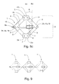
- a full scissor lifting arrangement 1 has a foot 2 for resting the lifting arrangement against a supporting surface.
- Figure 8a illustrates the full scissor lifting arrangement 1 in a collapsed position, figure 8b in an intermediate position and figure 8c in an extended position.
- the scissor lifting arrangement 1 further comprises a first arm 4 and a second arm 4' and a first leg 3 and a second leg 3', each having respective first and second longitudinal ends (4a, 4b, 4'a, 4'b, 3a, 3b, 3'a, 3'b).
- the first longitudinal end 4a of the first arm 4 is pivotally coupled to the first leg 3 at the second longitudinal end 3b thereof to form a first knee 18.
- the first leg 3 and the second leg 3' are pivotally coupled to the foot 2 at the respective first longitudinal ends 3a, 3'a thereof.
- the first longitudinal end 4'a of the second arm 4' is pivotally coupled to the second leg 3' at the second longitudinal end 3'b thereof to form a second knee 19.
- a head 5 is also provided for supporting a load to be lifted.
- the head 5 is pivotally coupled to the respective second longitudinal ends 4b, 4'b of the arms 4, 4'.
- a primary actuation mechanism comprising a drive screw 6, a nut 7 and a nut-carrier 8 is provided, by which a separation distance S between the head 5 and the foot 2 is adjustable between an extended position, as illustrated in figure 8c , and a collapsed position, as illustrated in figure 8a .
- the nut 7 is held by the nut-carrier 8 at which, during rotation of the drive screw 6, it is arranged to be translated between a first end R1 and a second end R2 of a predetermined range R.
- the drive screw 6 and nut-carrier 8 are respectively operatively coupled to the arms 4, 4' and legs 3, 3' at the first and second knees 18, 19.
- Rotation of the drive screw 6 in a first direction, from a minimum separation distance, as illustrated in figure 8a causes translation of the nut 7 towards the first end R1 of the predetermined range R.
- the arms 4, 4'and legs 3, 3' will be pulled towards respective more extended positions, which increases the separation distance S.
- Subsequent rotation of the drive screw 6 in a second direction, opposite to the first direction decreases the separation distance S, and sustained rotation of the drive screw 6 in the second direction, causes translation of the nut 7 towards the second end R2 of the predetermined range R at the minimum separation distance, as illustrated in figure 8a .
- a secondary actuation mechanism is arranged to be effected by translation of the nut 7 from the second end R2 towards the first end R1 of the predetermined range R at the nut-carrier 8 to cause at least one of the legs 3, 3' and the arms 4, 4' to be pushed towards a more extended position, which increases the separation distance S.
- Such alternative secondary actuation mechanisms include: a combination of a wedge shaped nut 7 and at least one roller 9a; a combination of a nut 7 and at least one curved cam 11; a combination of a nut 7 and at least one linkarm 12; a combination of a nut 7 having an external rack 13 and a at least one pinion gear 14 arranged to drive a lifter 15; and a combination of a nut 7 having an external rack 13 and a at least one pinion gear 14 carrying a cam 16, as illustrated in figures 3 - 6 .
- the full scissor lifting arrangement 1 according to figures 8a, 8b and 8c can also be provided with a locking arrangement 17 enabling selective locking and release of the nut 7 to the nut-carrier 8, which, as illustrated in the figure 7 embodiment, can comprise a ratchet 17 arranged to selectively lock the nut 7 to the nut-carrier 8 at either of the first end R1 and the second end R2 of the predetermined range R.
- the full scissor lifting arrangement 1 according to figures 8a, 8b and 8c can also, in some embodiments, be provided with a manual release actuator (not shown) for effecting manual release of the nut 7 when locked to the nut-carrier 8, or an automatic release actuator (not shown) for effecting automatic release of the nut 7 when locked to the nut-carrier 8 at a predetermined separation distance S between the foot 2 and head 5.
- a manual release actuator not shown
- an automatic release actuator for effecting automatic release of the nut 7 when locked to the nut-carrier 8 at a predetermined separation distance S between the foot 2 and head 5.
- the full scissor lifting arrangement 1 according to figures 8a, 8b and 8c can also, in some embodiments, be provided with a damping arrangement (not shown) arranged to damp translation of the nut 7 at the nut-carrier 8, which damping arrangement in some embodiments can comprise at least one of a rubber bushing, a fluid damper, and a spring.
- a scissor lifting cluster arrangement as above, where the drive screws 6 of the scissor lifting arrangements 1 are arranged to be operated in synchronicity provides for highly stable lifting applications involving multiple scissor lifting arrangements 1 which are perfectly synchronized with each other and operable with one common crank.
- a vehicle lifting jack comprising a scissor lifting arrangement 1 as described in the foregoing.
- a vehicle lifting jack that comprises a scissor lifting arrangement 1, as above, is able to lift a vehicle from a low position and may also be collapsed and stowed efficiently in the vehicle.
Landscapes
- Life Sciences & Earth Sciences (AREA)
- Engineering & Computer Science (AREA)
- Geology (AREA)
- Mechanical Engineering (AREA)
- Structural Engineering (AREA)
- Prostheses (AREA)
Priority Applications (3)
| Application Number | Priority Date | Filing Date | Title |
|---|---|---|---|
| EP14171916.1A EP2955148A1 (de) | 2014-06-11 | 2014-06-11 | Scherenhubanordnung |
| EP15728501.6A EP3154895B1 (de) | 2014-06-11 | 2015-06-10 | Scherenhubanordnung |
| PCT/EP2015/062922 WO2015189260A1 (en) | 2014-06-11 | 2015-06-10 | Scissor lifting arrangement |
Applications Claiming Priority (1)
| Application Number | Priority Date | Filing Date | Title |
|---|---|---|---|
| EP14171916.1A EP2955148A1 (de) | 2014-06-11 | 2014-06-11 | Scherenhubanordnung |
Publications (1)
| Publication Number | Publication Date |
|---|---|
| EP2955148A1 true EP2955148A1 (de) | 2015-12-16 |
Family
ID=50927972
Family Applications (2)
| Application Number | Title | Priority Date | Filing Date |
|---|---|---|---|
| EP14171916.1A Withdrawn EP2955148A1 (de) | 2014-06-11 | 2014-06-11 | Scherenhubanordnung |
| EP15728501.6A Active EP3154895B1 (de) | 2014-06-11 | 2015-06-10 | Scherenhubanordnung |
Family Applications After (1)
| Application Number | Title | Priority Date | Filing Date |
|---|---|---|---|
| EP15728501.6A Active EP3154895B1 (de) | 2014-06-11 | 2015-06-10 | Scherenhubanordnung |
Country Status (2)
| Country | Link |
|---|---|
| EP (2) | EP2955148A1 (de) |
| WO (1) | WO2015189260A1 (de) |
Citations (4)
| Publication number | Priority date | Publication date | Assignee | Title |
|---|---|---|---|---|
| US1991255A (en) * | 1932-02-29 | 1935-02-12 | Martin Louis Joseph Henri | Elevator for any applications |
| US2560797A (en) * | 1946-07-10 | 1951-07-17 | Marion W Humphreys | Jack |
| GB2125007A (en) | 1982-08-09 | 1984-02-29 | Kenneth Mortimer | Scissor type jack |
| WO2001072627A1 (de) * | 2000-03-27 | 2001-10-04 | Thyssenkrupp Bilstein Gmbh | Wagenheber |
-
2014
- 2014-06-11 EP EP14171916.1A patent/EP2955148A1/de not_active Withdrawn
-
2015
- 2015-06-10 WO PCT/EP2015/062922 patent/WO2015189260A1/en active Application Filing
- 2015-06-10 EP EP15728501.6A patent/EP3154895B1/de active Active
Patent Citations (4)
| Publication number | Priority date | Publication date | Assignee | Title |
|---|---|---|---|---|
| US1991255A (en) * | 1932-02-29 | 1935-02-12 | Martin Louis Joseph Henri | Elevator for any applications |
| US2560797A (en) * | 1946-07-10 | 1951-07-17 | Marion W Humphreys | Jack |
| GB2125007A (en) | 1982-08-09 | 1984-02-29 | Kenneth Mortimer | Scissor type jack |
| WO2001072627A1 (de) * | 2000-03-27 | 2001-10-04 | Thyssenkrupp Bilstein Gmbh | Wagenheber |
Also Published As
| Publication number | Publication date |
|---|---|
| WO2015189260A1 (en) | 2015-12-17 |
| EP3154895B1 (de) | 2018-08-01 |
| EP3154895A1 (de) | 2017-04-19 |
Similar Documents
| Publication | Publication Date | Title |
|---|---|---|
| RU2488523C2 (ru) | Устройство уменьшения длины шасси летательного аппарата | |
| EP2893830A1 (de) | Klappstuhl | |
| CN102239085B (zh) | 具有双钩机构的起落架舱门 | |
| US20130299633A1 (en) | Landing gear for an aircraft | |
| CN105383685A (zh) | 起落架组件 | |
| CN105390796B (zh) | 一种机械自锁式雷达天线举升机构 | |
| US20110041738A1 (en) | Mobile folding table with improved locking and lift-assisting mechanisms | |
| CN102381291B (zh) | 一种伸缩支腿及具有该伸缩支腿的工程机械 | |
| JP2012528759A (ja) | 折りたたみ支柱を有する着陸装置を作動させる方法 | |
| US10737762B2 (en) | Latching and locking mechanism for a foldable wing arrangement | |
| CN103917446A (zh) | 飞机起落架 | |
| EP3069991B1 (de) | Flugzeugfahrwerkanordnung | |
| EP3176073B1 (de) | Doppelfunktionsverrieglungs- und faltanordnung für eine flugzeugflügelspitzenvorrichtung | |
| CN104995088A (zh) | 带有可变阻尼的俯仰调整致动器 | |
| EP3154895B1 (de) | Scherenhubanordnung | |
| CN109996522B (zh) | 用于轮椅的改进的剪式升降机 | |
| EP3681796B1 (de) | Faltbares fahrwerk | |
| US20170369289A1 (en) | Expandable car jack | |
| FI57652C (fi) | Manoevreringsorgan | |
| CN1749152B (zh) | 特别用于机动车辆的汽车升降器用执行单元 | |
| ITUB20154754A1 (it) | Piantone di sterzo | |
| CN211397110U (zh) | 一种人井钥匙 | |
| IT201700002675A1 (it) | Piantone di sterzo | |
| US11919757B2 (en) | Scissor jack | |
| EP3385212B1 (de) | Gehebeltes kipp- oder hubscherensystem, verfahren zum betrieb und verwendungen davon |
Legal Events
| Date | Code | Title | Description |
|---|---|---|---|
| PUAI | Public reference made under article 153(3) epc to a published international application that has entered the european phase |
Free format text: ORIGINAL CODE: 0009012 |
|
| AK | Designated contracting states |
Kind code of ref document: A1 Designated state(s): AL AT BE BG CH CY CZ DE DK EE ES FI FR GB GR HR HU IE IS IT LI LT LU LV MC MK MT NL NO PL PT RO RS SE SI SK SM TR |
|
| AX | Request for extension of the european patent |
Extension state: BA ME |
|
| STAA | Information on the status of an ep patent application or granted ep patent |
Free format text: STATUS: THE APPLICATION IS DEEMED TO BE WITHDRAWN |
|
| 18D | Application deemed to be withdrawn |
Effective date: 20160617 |