EP2955148A1 - Scissor lifting arrangement - Google Patents
Scissor lifting arrangement Download PDFInfo
- Publication number
- EP2955148A1 EP2955148A1 EP14171916.1A EP14171916A EP2955148A1 EP 2955148 A1 EP2955148 A1 EP 2955148A1 EP 14171916 A EP14171916 A EP 14171916A EP 2955148 A1 EP2955148 A1 EP 2955148A1
- Authority
- EP
- European Patent Office
- Prior art keywords
- nut
- leg
- arm
- foot
- carrier
- Prior art date
- Legal status (The legal status is an assumption and is not a legal conclusion. Google has not performed a legal analysis and makes no representation as to the accuracy of the status listed.)
- Withdrawn
Links
Images


Classifications
-
- B—PERFORMING OPERATIONS; TRANSPORTING
- B66—HOISTING; LIFTING; HAULING
- B66F—HOISTING, LIFTING, HAULING OR PUSHING, NOT OTHERWISE PROVIDED FOR, e.g. DEVICES WHICH APPLY A LIFTING OR PUSHING FORCE DIRECTLY TO THE SURFACE OF A LOAD
- B66F3/00—Devices, e.g. jacks, adapted for uninterrupted lifting of loads
- B66F3/08—Devices, e.g. jacks, adapted for uninterrupted lifting of loads screw operated
- B66F3/12—Devices, e.g. jacks, adapted for uninterrupted lifting of loads screw operated comprising toggle levers
Definitions
- the present application relate to a scissor lifting arrangement, and especially a scissor lifting arrangement suitable for use as a motor vehicle lifting jack.
- Scissor lifting arrangements such as half scissors and full scissors, are frequently used to provide cost efficient lifting capabilities.
- a head and a foot are interconnected by a pair of arms pivotally joined to the head and a pair of legs pivotally joined to the foot. Each respective pair of one arm and one leg is then further pivotally joined at a respective knee.
- a screw is attached to one of the two knees with a bearing (glide or ball bearing) and a nut held by a nut-carrier is attached to the other knee.
- a mechanism is provided for turning the screw, such that as the screw is turned the two knees of the full scissor lifting arrangement are forced together causing a distance between a head and a foot to increase.
- Scissor lifting arrangements both Full Scissor and Half Scissor lifting arrangements, which e.g. are the most common lifting jack concepts in the automotive industry, have a great weakness in that they are very weak as long as they are in a low position. This as the geometry for pulling the arms and legs thereof more upright from a low position is very unfavorable.
- this retracted, low, position is today normally only used for storage of the scissor lifting arrangement, e.g. storage of a lifting jack in the trunk of an automobile.
- Examples of such situations where the space between the jacking point at the vehicle body and the ground may be insufficient include situations such as: multiple tyres punctured on one side of the vehicle, vehicle placed on uneven ground, a need to place a support under the lifting jack due to soft ground or similar.
- a scissor type lifting jack similar to that already described above is shown in which a linear actuator consists of a screw connected, not between the knees as above, but in accordance with GB 2125007 between levers protruding from the legs, and more specifically to pivotal connections at these levers which pivotal connections, in the lowermost position of figure 13, are offset from the pivot joints at the knees and the pivotal connections to the foot, i.e. offset from a plane through all of these pivotal connections.
- these levers will provide leverage to assist operation of the jack, especially from the fully retracted condition.
- offset pivotal connections are shown in the vicinity of the pivot joints at the knees, they may be located intermediate the pivotal connections at the knees and the foot or beyond (i.e. outwardly) of the pivot joints at the knees, in order to provide suitable leverage.
- the screw is threaded at through a cross pin at one pivotal connection to one of these levers and a plain portion of the screw rod is rotatable through another cross pin at the other pivotal connection to the other lever and is constrained against axial movement relative to the other cross pin mainly by a thrust bearing and also by a washer located by projections on the plain rod portion.
- a turning eye is provided at the non-threaded end of the screw.
- Embodiments herein aim to provide an improved scissor lifting arrangement which is simple, practical and cost-effective in construction and is effective in its action; and by the use of which a heavy load may be easily lifted even when the lifting arrangement is lowered to its minimum height.
- a scissor lifting arrangement that comprises: a foot for resting the lifting arrangement against a supporting surface; at least one leg having first and second longitudinal ends, the leg being pivotally coupled to the foot at the first longitudinal end thereof; at least one arm having first and second longitudinal ends, the first longitudinal end of the arm being pivotally coupled to the leg; a head for supporting a load to be lifted, the head being pivotally coupled to the second longitudinal end of the arm; a primary actuation mechanism, comprising a drive screw, a nut and a nut-carrier, by which a separation distance between the head and the foot is adjustable between an extended and a collapsed position; where the nut is held by the nut-carrier at which, during rotation of the drive screw, it is arranged to be translated between a first end and a second end of a predetermined range; the drive screw and nut-carrier are respectively operatively coupled to an arm and a leg, so that rotation of the drive screw in a first direction, from a minimum separation distance, causes translation of
- the secondary actuation mechanism is based on a combination of a wedge shaped nut and at least one cam arranged at at least one of the leg, the arm, the head and the foot such that the cam will be contacted by the wedge shaped nut upon translation of the nut towards the first end of the predetermined range at the nut-carrier to cause at least one of the leg, the arm, the head and the foot to be pushed towards a more extended position.
- the secondary actuation mechanism is based on a combination of a wedge shaped nut and at least one roller arranged at at least one of the leg, the arm, the head and the foot such that the roller will be contacted by the wedge shaped nut upon translation of the nut towards the first end of the predetermined range at the nut-carrier to cause at least one of the leg, the arm, the head and the foot to be pushed towards a more extended position.
- a combination of a wedge shaped nut and at least one roller provides for a low friction mechanism making it either easier to turn the drive screw or possible to have a steeper angle wedge shaped nut, providing for increased lift by the secondary actuation mechanism.
- the secondary actuation mechanism is based on a combination of a nut and at least one curved cam arranged at at least one of the leg, the arm, the head and the foot such that the curved cam will be contacted by the nut upon translation of the nut towards the first end of the predetermined range at the nut-carrier to cause at least one of the leg, the arm, the head and the foot to be pushed towards a more extended position.
- the secondary actuation mechanism is based on a combination of a nut and at least one linkarm operatively coupled to at least one of the leg, the arm, the head and the foot such that the linkarm will be contacted by the nut upon translation of the nut towards the first end of the predetermined range at the nut-carrier to cause at least one of the leg, the arm, the head and the foot to be pushed towards a more extended position.
- the secondary actuation mechanism is based on a combination of a nut having an external rack and a at least one pinion gear arranged to drive a lifter arranged to operate at at least one of the leg, the arm, the head and the foot such that the pinion gear will be rotated by the rack of the nut upon translation of the nut towards the first end of the predetermined range at the nut-carrier to cause at least one of the leg, the arm, the head and the foot to be pushed towards a more extended position.
- the secondary actuation mechanism is based on a combination of a nut having an external rack and a at least one pinion gear carrying a cam arranged to operate at at least one of the leg, the arm, the head and the foot such that the pinion gear will be rotated by the rack of the nut upon translation of the nut towards the first end of the predetermined range at the nut-carrier to cause at least one of the leg, the arm, the head and the foot to be pushed towards a more extended position.
- it further comprises a locking arrangement enabling selective locking and release of the nut to the nut-carrier, when locked inhibiting translation of the nut at the nut-carrier.
- a locking arrangement enabling selective locking and release of the nut to the nut-carrier provides for enhanced stability and enables well controlled angles of the arms and legs of the scissor lifting arrangement through eliminating the ability of the nut to be translated at the nut-carrier.
- the locking arrangement comprises a ratchet arranged to selectively lock the nut to the nut-carrier at either of the first end and the second end of the predetermined range.
- a manual release actuator for effecting manual release of the nut when locked to the nut-carrier.
- an eleventh aspect further comprises an automatic release actuator for effecting automatic release of the nut when locked to the nut-carrier at a predetermined separation distance between the foot and head.
- the scissor lifting arrangement further comprises a first arm and a second arm and a first leg and a second leg; and that the first longitudinal end of the first arm is pivotally coupled to the first leg at the second longitudinal end thereof to form a first knee; the second leg has first and second longitudinal ends, the second leg is pivotally coupled to the foot at the first longitudinal end thereof; the second arm has first and second longitudinal ends, the first longitudinal end of the second arm is pivotally coupled to the second leg at the second longitudinal end thereof to form a second knee; the drive screw and nut-carrier are respectively operatively coupled to the arms and legs at the first and second knees.
- a vehicle lifting jack which comprises a scissor lifting arrangement as above provides for a simple and reliable lifting jack which is able to lift a vehicle from a low position and which may be collapsed and stowed efficiently in the vehicle.
- a scissor lifting arrangement 1 which, although primarily intended for use as a vehicle lifting jack, with appropriate adaption is capable of a wide variety of practical applications, e.g. where lifting, lateral displacement or pressure application is required.
- the scissor lifting arrangement 1 has a foot 2 for resting the lifting arrangement against a supporting surface. At least one leg 3 having first and second longitudinal ends 3a, 3b is provided. The leg 3 is pivotally coupled to the foot 2 at the first longitudinal end 3a thereof. At least one arm 4 having first and second longitudinal ends 4a, 4b is provided. The first longitudinal end 4a of the arm 4 is pivotally coupled to the leg 3. A head 5 is also provided for supporting a load to be lifted. The head 5 is pivotally coupled to the second longitudinal end 4b of the arm 4.
- a primary actuation mechanism comprising a drive screw 6, a nut 7 and a nut-carrier 8 is provided, by which a separation distance S between the head 5 and the foot 2 is adjustable between an extended position, c.f. figure 1c , and a collapsed position, c.f. figure 1 a.
- the nut 7 is held by the nut-carrier 8 at which, during rotation of the drive screw 6, it is arranged to be translated between a first end R1 and a second end R2 of a predetermined range R.
- the predetermined range R is delimited by an end stop at at least the first end R1 thereof, such that the nut 7 will abut the end stop at the first end R1 thereof and cause the nut-carrier 8 to move with the nut 7 in the first direction, i.e. a direction extended from R2 towards R1, should the nut be translated in the first direction.
- the nut-carrier 8 may e.g. be a bracket, as illustrated in the figures, inside of which the nut 7 is held translatable the predetermined range R.
- the nut-carrier 8 may be at least one transverse pin (not shown), e.g. at a pivotal joint, which transverse pin runs through an elongated opening (not shown) in the nut 7 or any structure fixedly joined to the nut 7.
- the elongated opening should then have an extension corresponding to the predetermined range R and be arranged such that the nut 7 may be translated the predetermined range R upon the transverse pin.
- pins from two opposing sides (not shown) which runs in opposing side elongated slots in the nut 7 or any structure fixedly joined to the nut 7.
- the elongated slots should then also have extensions corresponding to the predetermined range R and be arranged such that the nut 7 may be translated the predetermined range R upon the opposing side pins.
- any arrangement of a nut-carrier 8 which allows the nut 7 to be translated the predetermined range R through turning of the drive screw 6 for affecting the functionality described herein may be feasible for realization of the scissor lifting arrangement 1 described herein.
- the drive screw 6 and nut-carrier 8 are respectively operatively coupled to an arm 4 and a leg 3.
- the drive screw 6 is threaded through the nut 7 held by the nut-carrier 8 which is pivotally connected to one of the arm 4 or the leg 3 and a plain portion of the rod shaped drive screw 6 is rotatable through a cross element 10 at another pivotal connection to the other of arm 4 and leg 3 and is constrained against axial movement relative to the cross element 10, e.g. by a thrust bearing, such as a glide or ball bearing (not shown).
- a turning eye 6a or another kind of cranking arrangement is provided at the non-threaded end of the drive screw 6.
- Rotation of the drive screw 6 in a first direction causes translation of the nut 7 towards the first end R1 of the predetermined range R.
- the arm 4 and leg 3 Upon sustained rotation of the drive screw 6 in the first direction thereafter, the arm 4 and leg 3 will be pulled towards respective more extended positions, which increases the separation distance S.
- a secondary actuation mechanism is arranged to be effected by translation of the nut 7 from the second R2 end towards the first end R1 of the predetermined range R at the nut-carrier 8 to cause at least one of the leg 3, the arm 4, the head 5 and the foot 2 to be pushed towards a more extended position, which increases the separation distance S.
- the secondary actuation mechanism can be based on a combination of a wedge shaped nut 7 and at least one cam 9 arranged at at least one of the leg 3, the arm 4, the head 5 and the foot 2 such that the cam 9 will be contacted by the wedge shaped nut 7 upon translation of the nut 7 towards the first end R1 of the predetermined range R at the nut-carrier 8 to cause at least one of the leg 3, the arm 4, the head 5 and the foot 2 to be pushed towards a more extended position, as illustrated in figure 1 b.
- the secondary actuation mechanism can be based on a combination of a wedge shaped nut 7 and at least one roller 9a arranged at at least one of the leg 3, the arm 4, the head 5 and the foot 2 such that the roller 9a will be contacted by the nut 7 upon translation of the nut 7 towards the first end R1 of the predetermined range R at the nut-carrier 8 to cause at least one of the leg 3, the arm 4, the head 5 and the foot 2 to be pushed towards a more extended position, as illustrated in figure 2b .
- the roller 9a may be carried by a roller bracket or a tappet, in relation to which it may be arranged to rotate by a bearing, such as a glide or ball-bearing.
- the secondary actuation mechanism can be based on a combination of a nut 7 and at least one curved cam 11 arranged at at least one of the leg 3, the arm 4, the head 5 and the foot 2 such that the curved cam 11 will be contacted by the nut 7 upon translation of the nut 7 towards the first end R1 of the predetermined range R at the nut-carrier 8 to cause at least one of the leg 3, the arm 4, the head 5 and the foot 2 to be pushed towards a more extended position.
- the secondary actuation mechanism is based on a combination of a nut 7 having an external rack 13 and a at least one pinion gear 14 carrying a cam 16 arranged to operate at at least one of the leg 3, the arm 4, the head 5 and the foot 2 such that the pinion gear 14 will be rotated by the rack 13 of the nut 7 upon translation of the nut 7 towards the first end R1 of the predetermined range R at the nut-carrier 8 to cause at least one of the leg 3, the arm 4, the head 5 and the foot 2 to be pushed towards a more extended position.
- the scissor lifting arrangement 1 further comprises a locking arrangement 17 enabling selective locking and release of the nut 7 to the nut-carrier 8, as illustrated in figure 7 , which when locked inhibits translation of the nut 7 at the nut-carrier 8.
- the locking arrangement in 17 some embodiments comprises a ratchet 17 arranged to selectively lock the nut 7 to the nut-carrier 8 at either of the first end R1 and the second end R2 of the predetermined range R.
- the locking arrangement 17 further comprises a manual release actuator (not shown) for effecting manual release of the nut 7 when locked to the nut-carrier 8, and in other embodiments the locking arrangement 17 further comprises an automatic release actuator (not shown) for effecting automatic release of the nut 7 when locked to the nut-carrier 8 at a predetermined separation distance S between the foot 2 and head 5.
- the lifting arrangement 1 further comprises a damping arrangement (not shown) arranged to damp translation of the nut 7 at the nut-carrier 8.
- the damping arrangement in some embodiments comprises at least one of a rubber bushing, a fluid damper, a spring.
- a full scissor lifting arrangement 1 has a foot 2 for resting the lifting arrangement against a supporting surface.
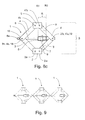
- Figure 8a illustrates the full scissor lifting arrangement 1 in a collapsed position, figure 8b in an intermediate position and figure 8c in an extended position.
- the scissor lifting arrangement 1 further comprises a first arm 4 and a second arm 4' and a first leg 3 and a second leg 3', each having respective first and second longitudinal ends (4a, 4b, 4'a, 4'b, 3a, 3b, 3'a, 3'b).
- the first longitudinal end 4a of the first arm 4 is pivotally coupled to the first leg 3 at the second longitudinal end 3b thereof to form a first knee 18.
- the first leg 3 and the second leg 3' are pivotally coupled to the foot 2 at the respective first longitudinal ends 3a, 3'a thereof.
- the first longitudinal end 4'a of the second arm 4' is pivotally coupled to the second leg 3' at the second longitudinal end 3'b thereof to form a second knee 19.
- a head 5 is also provided for supporting a load to be lifted.
- the head 5 is pivotally coupled to the respective second longitudinal ends 4b, 4'b of the arms 4, 4'.
- a primary actuation mechanism comprising a drive screw 6, a nut 7 and a nut-carrier 8 is provided, by which a separation distance S between the head 5 and the foot 2 is adjustable between an extended position, as illustrated in figure 8c , and a collapsed position, as illustrated in figure 8a .
- the nut 7 is held by the nut-carrier 8 at which, during rotation of the drive screw 6, it is arranged to be translated between a first end R1 and a second end R2 of a predetermined range R.
- the drive screw 6 and nut-carrier 8 are respectively operatively coupled to the arms 4, 4' and legs 3, 3' at the first and second knees 18, 19.
- Rotation of the drive screw 6 in a first direction, from a minimum separation distance, as illustrated in figure 8a causes translation of the nut 7 towards the first end R1 of the predetermined range R.
- the arms 4, 4'and legs 3, 3' will be pulled towards respective more extended positions, which increases the separation distance S.
- Subsequent rotation of the drive screw 6 in a second direction, opposite to the first direction decreases the separation distance S, and sustained rotation of the drive screw 6 in the second direction, causes translation of the nut 7 towards the second end R2 of the predetermined range R at the minimum separation distance, as illustrated in figure 8a .
- a secondary actuation mechanism is arranged to be effected by translation of the nut 7 from the second end R2 towards the first end R1 of the predetermined range R at the nut-carrier 8 to cause at least one of the legs 3, 3' and the arms 4, 4' to be pushed towards a more extended position, which increases the separation distance S.
- Such alternative secondary actuation mechanisms include: a combination of a wedge shaped nut 7 and at least one roller 9a; a combination of a nut 7 and at least one curved cam 11; a combination of a nut 7 and at least one linkarm 12; a combination of a nut 7 having an external rack 13 and a at least one pinion gear 14 arranged to drive a lifter 15; and a combination of a nut 7 having an external rack 13 and a at least one pinion gear 14 carrying a cam 16, as illustrated in figures 3 - 6 .
- the full scissor lifting arrangement 1 according to figures 8a, 8b and 8c can also be provided with a locking arrangement 17 enabling selective locking and release of the nut 7 to the nut-carrier 8, which, as illustrated in the figure 7 embodiment, can comprise a ratchet 17 arranged to selectively lock the nut 7 to the nut-carrier 8 at either of the first end R1 and the second end R2 of the predetermined range R.
- the full scissor lifting arrangement 1 according to figures 8a, 8b and 8c can also, in some embodiments, be provided with a manual release actuator (not shown) for effecting manual release of the nut 7 when locked to the nut-carrier 8, or an automatic release actuator (not shown) for effecting automatic release of the nut 7 when locked to the nut-carrier 8 at a predetermined separation distance S between the foot 2 and head 5.
- a manual release actuator not shown
- an automatic release actuator for effecting automatic release of the nut 7 when locked to the nut-carrier 8 at a predetermined separation distance S between the foot 2 and head 5.
- the full scissor lifting arrangement 1 according to figures 8a, 8b and 8c can also, in some embodiments, be provided with a damping arrangement (not shown) arranged to damp translation of the nut 7 at the nut-carrier 8, which damping arrangement in some embodiments can comprise at least one of a rubber bushing, a fluid damper, and a spring.
- a scissor lifting cluster arrangement as above, where the drive screws 6 of the scissor lifting arrangements 1 are arranged to be operated in synchronicity provides for highly stable lifting applications involving multiple scissor lifting arrangements 1 which are perfectly synchronized with each other and operable with one common crank.
- a vehicle lifting jack comprising a scissor lifting arrangement 1 as described in the foregoing.
- a vehicle lifting jack that comprises a scissor lifting arrangement 1, as above, is able to lift a vehicle from a low position and may also be collapsed and stowed efficiently in the vehicle.
Abstract
A scissor lifting arrangement (1) comprising: a foot (2); at least one leg (3) pivotally coupled to the foot (2); at least one arm (4) pivotally coupled to the leg (3); a head (5) pivotally coupled to the arm (4); a primary actuation mechanism, comprising a drive screw (6), a nut (7) and a nut-carrier (8). The screw (6) and nut-carrier (8) are respectively operatively coupled to an arm (4) and a leg (3), so that rotation of the screw (6) in a first direction, from a minimum separation distance (S), causes translation of the nut (7) towards a first end of a predetermined range (R) at the nut-carrier (8) and a subsequent increase in separation distance (S) upon further rotation, and vice versa. A secondary actuation mechanism is arranged to be effected by translation of the nut (7) towards the first end (R1) of the predetermined range (R) to cause at least one of the leg (3), the arm (4), the head (5) and the foot (2) to be pushed towards a more extended position, for an increased separation distance (S).


Description
- The present application relate to a scissor lifting arrangement, and especially a scissor lifting arrangement suitable for use as a motor vehicle lifting jack.
- Scissor lifting arrangements, such as half scissors and full scissors, are frequently used to provide cost efficient lifting capabilities.
- In a full scissor lifting arrangement a head and a foot are interconnected by a pair of arms pivotally joined to the head and a pair of legs pivotally joined to the foot. Each respective pair of one arm and one leg is then further pivotally joined at a respective knee. A screw is attached to one of the two knees with a bearing (glide or ball bearing) and a nut held by a nut-carrier is attached to the other knee. A mechanism is provided for turning the screw, such that as the screw is turned the two knees of the full scissor lifting arrangement are forced together causing a distance between a head and a foot to increase. When the full scissor lifting arrangement is closed, i.e. in a position where the head and foot are near each other, it is very weak. When the arms and the legs are close to a straight line, i.e. maximum separation between the head and foot, the full scissor lifting arrangement is very strong.
- Scissor lifting arrangements (both Full Scissor and Half Scissor lifting arrangements), which e.g. are the most common lifting jack concepts in the automotive industry, have a great weakness in that they are very weak as long as they are in a low position. This as the geometry for pulling the arms and legs thereof more upright from a low position is very unfavorable.
- Thus, such lifting arrangements are often difficult to operate, especially from a fully retracted condition. In a retracted, low, position a scissor lifting arrangement is as weakest. Even if applying large forces to a screw of a scissor lifting arrangement, resulting in huge forces in the arm(s) and joint(s) thereof, a very limited lifting force is generated to overcome any load placed upon the scissor lifting arrangement.
- Thus, this retracted, low, position is today normally only used for storage of the scissor lifting arrangement, e.g. storage of a lifting jack in the trunk of an automobile.
- For an automotive lifting jack, in the ideal situation, the space between the jacking point at a vehicle body and the ground is sufficiently large, such that the lifting jack can rise to a stronger position before it touches the vehicle body and starts to carry any load. However, several situations can occur, all of which may be considered as some kind of misuse, usually prohibited in the owner's manual of the automobile.
- Examples of such situations where the space between the jacking point at the vehicle body and the ground may be insufficient include situations such as: multiple tyres punctured on one side of the vehicle, vehicle placed on uneven ground, a need to place a support under the lifting jack due to soft ground or similar.
- Other situations, where the space between the jacking point and the ground may be insufficient, includes situations where a user attempts to lift loads other than such for which the lifting jack was designed.
- Thus, the inability to provide adequate lifting force from a retracted, low, position, i.e. small separation between head and foot, is a known limitation of prior-art scissor lifting arrangements.
- Several attempts have been made at providing scissor lifting arrangements having improved small separation lifting capabilities. One such attempt is described by the embodiment of figures 12 to 14 of document
GB 2125007 - Referring to figures 12 to 14 of document
GB 2125007 GB 2125007 - The screw is threaded at through a cross pin at one pivotal connection to one of these levers and a plain portion of the screw rod is rotatable through another cross pin at the other pivotal connection to the other lever and is constrained against axial movement relative to the other cross pin mainly by a thrust bearing and also by a washer located by projections on the plain rod portion. A turning eye is provided at the non-threaded end of the screw.
- However, although an arrangement according to figures 12 to 14 of document
GB 2125007 - Embodiments herein aim to provide an improved scissor lifting arrangement which is simple, practical and cost-effective in construction and is effective in its action; and by the use of which a heavy load may be easily lifted even when the lifting arrangement is lowered to its minimum height.
- This is provided through a scissor lifting arrangement that comprises: a foot for resting the lifting arrangement against a supporting surface; at least one leg having first and second longitudinal ends, the leg being pivotally coupled to the foot at the first longitudinal end thereof; at least one arm having first and second longitudinal ends, the first longitudinal end of the arm being pivotally coupled to the leg; a head for supporting a load to be lifted, the head being pivotally coupled to the second longitudinal end of the arm; a primary actuation mechanism, comprising a drive screw, a nut and a nut-carrier, by which a separation distance between the head and the foot is adjustable between an extended and a collapsed position; where the nut is held by the nut-carrier at which, during rotation of the drive screw, it is arranged to be translated between a first end and a second end of a predetermined range; the drive screw and nut-carrier are respectively operatively coupled to an arm and a leg, so that rotation of the drive screw in a first direction, from a minimum separation distance, causes translation of the nut towards the first end of the predetermined range, where after, upon sustained rotation of the drive screw in the first direction, the arm and leg will be pulled towards respective more extended positions, which increases the separation distance; and subsequent rotation of the drive screw in a second direction, opposite to the first direction, decreases the separation distance, and sustained rotation of the drive screw in the second direction, causes translation of the nut towards the second end of the predetermined range at the minimum separation distance; and a secondary actuation mechanism arranged to be effected by translation of the nut from the second end towards the first end of the predetermined range at the nut-carrier to cause at least one of the leg, the arm, the head and the foot to be pushed towards a more extended position, which increases the separation distance.
- The provision of a secondary actuation mechanism where the translation of the nut is used to cause at least one of the leg, the arm, the head and the foot to be pushed towards a more extended position and increase the separation distance provides for an improved starting position for the primary actuation mechanism.
- According to a second aspect is provided that the secondary actuation mechanism is based on a combination of a wedge shaped nut and at least one cam arranged at at least one of the leg, the arm, the head and the foot such that the cam will be contacted by the wedge shaped nut upon translation of the nut towards the first end of the predetermined range at the nut-carrier to cause at least one of the leg, the arm, the head and the foot to be pushed towards a more extended position.
- The provision of a combination of a wedge shaped nut and at least one cam provides a simple and robust secondary actuation mechanism.
- According to a third aspect is provided that the secondary actuation mechanism is based on a combination of a wedge shaped nut and at least one roller arranged at at least one of the leg, the arm, the head and the foot such that the roller will be contacted by the wedge shaped nut upon translation of the nut towards the first end of the predetermined range at the nut-carrier to cause at least one of the leg, the arm, the head and the foot to be pushed towards a more extended position.
- The provision of a combination of a wedge shaped nut and at least one roller provides for a low friction mechanism making it either easier to turn the drive screw or possible to have a steeper angle wedge shaped nut, providing for increased lift by the secondary actuation mechanism.
- According to a fourth aspect is provided that the secondary actuation mechanism is based on a combination of a nut and at least one curved cam arranged at at least one of the leg, the arm, the head and the foot such that the curved cam will be contacted by the nut upon translation of the nut towards the first end of the predetermined range at the nut-carrier to cause at least one of the leg, the arm, the head and the foot to be pushed towards a more extended position.
- The provision of a combination of a nut and at least one curved cam provides for an alternative simple and robust secondary actuation mechanism.
- According to a fifth aspect is provided that the secondary actuation mechanism is based on a combination of a nut and at least one linkarm operatively coupled to at least one of the leg, the arm, the head and the foot such that the linkarm will be contacted by the nut upon translation of the nut towards the first end of the predetermined range at the nut-carrier to cause at least one of the leg, the arm, the head and the foot to be pushed towards a more extended position.
- The provision of a combination of a nut and at least one linkarm provides for yet an alternative simple and robust secondary actuation mechanism.
- According to a sixth aspect is provided that the secondary actuation mechanism is based on a combination of a nut having an external rack and a at least one pinion gear arranged to drive a lifter arranged to operate at at least one of the leg, the arm, the head and the foot such that the pinion gear will be rotated by the rack of the nut upon translation of the nut towards the first end of the predetermined range at the nut-carrier to cause at least one of the leg, the arm, the head and the foot to be pushed towards a more extended position.
- The provision of a combination of a nut having an external rack and a at least one pinion gear arranged to drive a lifter provides for a further alternative secondary actuation mechanism.
- According to a seventh aspect is provided that the secondary actuation mechanism is based on a combination of a nut having an external rack and a at least one pinion gear carrying a cam arranged to operate at at least one of the leg, the arm, the head and the foot such that the pinion gear will be rotated by the rack of the nut upon translation of the nut towards the first end of the predetermined range at the nut-carrier to cause at least one of the leg, the arm, the head and the foot to be pushed towards a more extended position.
- The provision of a combination of a nut having an external rack and a at least one pinion gear carrying a cam provides for a still further alternative secondary actuation mechanism.
- According to an eight aspect is provided that it further comprises a locking arrangement enabling selective locking and release of the nut to the nut-carrier, when locked inhibiting translation of the nut at the nut-carrier.
- The provision of a locking arrangement enabling selective locking and release of the nut to the nut-carrier provides for enhanced stability and enables well controlled angles of the arms and legs of the scissor lifting arrangement through eliminating the ability of the nut to be translated at the nut-carrier.
- According to a ninth aspect is provided that the locking arrangement comprises a ratchet arranged to selectively lock the nut to the nut-carrier at either of the first end and the second end of the predetermined range.
- The provision of a ratchet arranged to selectively lock the nut to the nut-carrier at either of the first end and the second end of the predetermined range provides for a simple and robust locking arrangement.
- According to a tenth aspect is provided that it further comprises a manual release actuator for effecting manual release of the nut when locked to the nut-carrier.
- The provision of a manual release actuator provides for simple and reliable transition between only allowing the primary actuation mechanism and allowing transitions between the first and second actuation mechanisms and vice versa.
- According to an eleventh aspect is provided that it further comprises an automatic release actuator for effecting automatic release of the nut when locked to the nut-carrier at a predetermined separation distance between the foot and head.
- The provision of an automatic release actuator for effecting automatic release at a predetermined separation distance provides for ensuring higher stability for some separation distances whilst enabling transitions between the first and second actuation mechanisms at other.
- According to an twelfth aspect is provided that it further comprises a damping arrangement arranged to damp translation of the nut at the nut-carrier.
- The provision of a damping arrangement provides for a reduced risk of free-play of the nut and thus improved stability of the scissor lifting arrangement.
- According to an thirteenth aspect is provided that the scissor lifting arrangement further comprises a first arm and a second arm and a first leg and a second leg; and that the first longitudinal end of the first arm is pivotally coupled to the first leg at the second longitudinal end thereof to form a first knee; the second leg has first and second longitudinal ends, the second leg is pivotally coupled to the foot at the first longitudinal end thereof; the second arm has first and second longitudinal ends, the first longitudinal end of the second arm is pivotally coupled to the second leg at the second longitudinal end thereof to form a second knee; the drive screw and nut-carrier are respectively operatively coupled to the arms and legs at the first and second knees.
- The provision of a second arm and a second leg provides for a full scissor lifting arrangement which is stable and reliable whilst being simple and robust.
- According to an fourteenth aspect is provided a scissor lifting cluster arrangement that comprises a plurality of scissor lifting arrangements as above the drive screws of which are arranged to be operated in synchronicity.
- The provision of a plurality of scissor lifting arrangements as above the drive screws of which are arranged to be operated in synchronicity provides for highly stable lifting applications involving multiple scissor lifting arrangements which are perfectly synchronized with each other and operable with one common crank.
- According to a final aspect is provided a vehicle lifting jack which comprises a scissor lifting arrangement as above.
- A vehicle lifting jack which comprises a scissor lifting arrangement as above provides for a simple and reliable lifting jack which is able to lift a vehicle from a low position and which may be collapsed and stowed efficiently in the vehicle.
- In the following, embodiments herein will be described in greater detail by way of example only with reference to attached drawings, in which
-
Figs. 1a, 1b and 1c are schematic illustrations of a scissor lifting arrangement having a secondary actuation mechanism based on a combination of a wedge shaped nut and a cam. -
Figs. 2a, 2b and 2c are schematic illustrations of a scissor lifting arrangement having a secondary actuation mechanism based on a combination of a wedge shaped nut and a roller. -
Fig. 3a, 3b and 3c are schematic illustrations of a scissor lifting arrangement having a secondary actuation mechanism based on a combination of a nut and at least one curved cam. -
Fig.4a, 4b and 4c are schematic illustrations of a scissor lifting arrangement having a secondary actuation mechanism is based on a combination of a nut and at least one linkarm. -
Fig. 5 is a schematic illustration of a scissor lifting arrangement having a secondary actuation mechanism is based on a combination of a nut having an external rack and a at least one pinion gear arranged to drive a lifter. -
Fig. 6 is a schematic illustration of a scissor lifting arrangement having a secondary actuation mechanism is based on a combination of a nut having an external rack and a at least one pinion gear carrying a cam. -
Fig. 7 is a schematic illustration of a scissor lifting arrangement further comprising a locking arrangement. -
Fig. 8 is a schematic illustration of a full scissor lifting arrangement according to embodiments herein. -
Fig. 9 is a schematic illustration of a scissor lifting cluster arrangement that comprises a plurality of scissor lifting arrangements the drive screws of which are arranged to be operated in synchronicity. - Still other objects and features of embodiments herein will become apparent from the following detailed description considered in conjunction with the accompanying drawings. It is to be understood, however, that the drawings are designed solely for purposes of illustration and not as a definition of the limits hereof, for which reference should be made to the appended claims. It should be further understood that the drawings are not necessarily drawn to scale and that, unless otherwise indicated, they are merely intended to conceptually illustrate the structures and procedures described herein.
- In overview, as illustrated in
figures 1a, 1b and 1c , embodiments herein relate to ascissor lifting arrangement 1 which, although primarily intended for use as a vehicle lifting jack, with appropriate adaption is capable of a wide variety of practical applications, e.g. where lifting, lateral displacement or pressure application is required. - The
scissor lifting arrangement 1 has afoot 2 for resting the lifting arrangement against a supporting surface. At least oneleg 3 having first and secondlongitudinal ends leg 3 is pivotally coupled to thefoot 2 at the firstlongitudinal end 3a thereof. At least onearm 4 having first and secondlongitudinal ends longitudinal end 4a of thearm 4 is pivotally coupled to theleg 3. Ahead 5 is also provided for supporting a load to be lifted. Thehead 5 is pivotally coupled to the secondlongitudinal end 4b of thearm 4. - A primary actuation mechanism, comprising a
drive screw 6, anut 7 and a nut-carrier 8 is provided, by which a separation distance S between thehead 5 and thefoot 2 is adjustable between an extended position, c.f.figure 1c , and a collapsed position, c.f.figure 1 a. The nut 7is held by the nut-carrier 8 at which, during rotation of thedrive screw 6, it is arranged to be translated between a first end R1 and a second end R2 of a predetermined range R. The predetermined range R is delimited by an end stop at at least the first end R1 thereof, such that thenut 7 will abut the end stop at the first end R1 thereof and cause the nut-carrier 8 to move with thenut 7 in the first direction, i.e. a direction extended from R2 towards R1, should the nut be translated in the first direction. - The nut-
carrier 8 may e.g. be a bracket, as illustrated in the figures, inside of which thenut 7 is held translatable the predetermined range R. Alternatively, the nut-carrier 8 may be at least one transverse pin (not shown), e.g. at a pivotal joint, which transverse pin runs through an elongated opening (not shown) in thenut 7 or any structure fixedly joined to thenut 7. The elongated opening should then have an extension corresponding to the predetermined range R and be arranged such that thenut 7 may be translated the predetermined range R upon the transverse pin. It is also feasible to have pins from two opposing sides (not shown) which runs in opposing side elongated slots in thenut 7 or any structure fixedly joined to thenut 7. The elongated slots should then also have extensions corresponding to the predetermined range R and be arranged such that thenut 7 may be translated the predetermined range R upon the opposing side pins. Further, any arrangement of a nut-carrier 8 which allows thenut 7 to be translated the predetermined range R through turning of thedrive screw 6 for affecting the functionality described herein may be feasible for realization of thescissor lifting arrangement 1 described herein. - The
drive screw 6 and nut-carrier 8 are respectively operatively coupled to anarm 4 and aleg 3. Thedrive screw 6 is threaded through thenut 7 held by the nut-carrier 8 which is pivotally connected to one of thearm 4 or theleg 3 and a plain portion of the rod shapeddrive screw 6 is rotatable through across element 10 at another pivotal connection to the other ofarm 4 andleg 3 and is constrained against axial movement relative to thecross element 10, e.g. by a thrust bearing, such as a glide or ball bearing (not shown). A turningeye 6a or another kind of cranking arrangement is provided at the non-threaded end of thedrive screw 6. - Rotation of the
drive screw 6 in a first direction, from a minimum separation distance as illustrated infigure 1a , causes translation of thenut 7 towards the first end R1 of the predetermined range R. Upon sustained rotation of thedrive screw 6 in the first direction thereafter, thearm 4 andleg 3 will be pulled towards respective more extended positions, which increases the separation distance S. Subsequent rotation of thedrive screw 6 in a second direction, opposite to the first direction, decreases the separation distance S, and sustained rotation of thedrive screw 6 in the second direction, causes translation of thenut 7 towards the second end R2 of the predetermined range S at the minimum separation distance, as illustrated infigure 1 a. - A secondary actuation mechanism is arranged to be effected by translation of the
nut 7 from the second R2 end towards the first end R1 of the predetermined range R at the nut-carrier 8 to cause at least one of theleg 3, thearm 4, thehead 5 and thefoot 2 to be pushed towards a more extended position, which increases the separation distance S. - As illustrated in
figures 1a, 1b and 1c , the secondary actuation mechanism can be based on a combination of a wedge shapednut 7 and at least onecam 9 arranged at at least one of theleg 3, thearm 4, thehead 5 and thefoot 2 such that thecam 9 will be contacted by the wedge shapednut 7 upon translation of thenut 7 towards the first end R1 of the predetermined range R at the nut-carrier 8 to cause at least one of theleg 3, thearm 4, thehead 5 and thefoot 2 to be pushed towards a more extended position, as illustrated infigure 1 b. - Alternatively, as illustrated in
figures 2a, 2b and 2c , the secondary actuation mechanism can be based on a combination of a wedge shapednut 7 and at least oneroller 9a arranged at at least one of theleg 3, thearm 4, thehead 5 and thefoot 2 such that theroller 9a will be contacted by thenut 7 upon translation of thenut 7 towards the first end R1 of the predetermined range R at the nut-carrier 8 to cause at least one of theleg 3, thearm 4, thehead 5 and thefoot 2 to be pushed towards a more extended position, as illustrated infigure 2b . Theroller 9a may be carried by a roller bracket or a tappet, in relation to which it may be arranged to rotate by a bearing, such as a glide or ball-bearing. - Alternatively, as illustrated in
figures 3a, 3b and 3c , the secondary actuation mechanism can be based on a combination of anut 7 and at least onecurved cam 11 arranged at at least one of theleg 3, thearm 4, thehead 5 and thefoot 2 such that thecurved cam 11 will be contacted by thenut 7 upon translation of thenut 7 towards the first end R1 of the predetermined range R at the nut-carrier 8 to cause at least one of theleg 3, thearm 4, thehead 5 and thefoot 2 to be pushed towards a more extended position. - In yet another alternative, as illustrated in
figures 4a, 4b and 4c , the secondary actuation mechanism is based on a combination of anut 7 and at least onelinkarm 12 operatively coupled to at least one of theleg 3, thearm 4, thehead 5 and thefoot 2 such that thelinkarm 12 will be contacted by thenut 7 upon translation of thenut 7 towards the first end R1 of the predetermined range R at the nut-carrier 8 to cause at least one of theleg 3, thearm 4, thehead 5 and thefoot 2 to be pushed towards a more extended position. - According to a still further alternative, as illustrated in
figure 5 , the secondary actuation mechanism is based on a combination of anut 7 having anexternal rack 13 and a at least onepinion gear 14 arranged to drive alifter 15 arranged to operate at at least one of theleg 3, thearm 4, thehead 5 and thefoot 2 such that thepinion gear 14 will be rotated by therack 13 of thenut 7 upon translation of thenut 7 towards the first end R1 of the predetermined range R at the nut-carrier 8 to cause at least one of theleg 3, thearm 4, thehead 5 and thefoot 2 to be pushed towards a more extended position. - In a yet further alternative, as illustrated in
figure 6 , the secondary actuation mechanism is based on a combination of anut 7 having anexternal rack 13 and a at least onepinion gear 14 carrying acam 16 arranged to operate at at least one of theleg 3, thearm 4, thehead 5 and thefoot 2 such that thepinion gear 14 will be rotated by therack 13 of thenut 7 upon translation of thenut 7 towards the first end R1 of the predetermined range R at the nut-carrier 8 to cause at least one of theleg 3, thearm 4, thehead 5 and thefoot 2 to be pushed towards a more extended position. - In some embodiments the
scissor lifting arrangement 1 further comprises a lockingarrangement 17 enabling selective locking and release of thenut 7 to the nut-carrier 8, as illustrated infigure 7 , which when locked inhibits translation of thenut 7 at the nut-carrier 8. - The locking arrangement in 17 some embodiments comprises a
ratchet 17 arranged to selectively lock thenut 7 to the nut-carrier 8 at either of the first end R1 and the second end R2 of the predetermined range R. - In some embodiments the locking
arrangement 17 further comprises a manual release actuator (not shown) for effecting manual release of thenut 7 when locked to the nut-carrier 8, and in other embodiments the lockingarrangement 17 further comprises an automatic release actuator (not shown) for effecting automatic release of thenut 7 when locked to the nut-carrier 8 at a predetermined separation distance S between thefoot 2 andhead 5. - In order to provide increased stability, in some further embodiments the lifting
arrangement 1 further comprises a damping arrangement (not shown) arranged to damp translation of thenut 7 at the nut-carrier 8. The damping arrangement in some embodiments comprises at least one of a rubber bushing, a fluid damper, a spring. - According to a currently preferred embodiment, as illustrated in
figures 8a, 8b and8c , a fullscissor lifting arrangement 1 has afoot 2 for resting the lifting arrangement against a supporting surface.Figure 8a illustrates the fullscissor lifting arrangement 1 in a collapsed position,figure 8b in an intermediate position andfigure 8c in an extended position. Thescissor lifting arrangement 1 further comprises afirst arm 4 and a second arm 4' and afirst leg 3 and a second leg 3', each having respective first and second longitudinal ends (4a, 4b, 4'a, 4'b, 3a, 3b, 3'a, 3'b). - The first
longitudinal end 4a of thefirst arm 4 is pivotally coupled to thefirst leg 3 at the secondlongitudinal end 3b thereof to form afirst knee 18. Thefirst leg 3 and the second leg 3' are pivotally coupled to thefoot 2 at the respective firstlongitudinal ends 3a, 3'a thereof. The first longitudinal end 4'a of the second arm 4' is pivotally coupled to the second leg 3' at the second longitudinal end 3'b thereof to form asecond knee 19. - A
head 5 is also provided for supporting a load to be lifted. Thehead 5 is pivotally coupled to the respective secondlongitudinal ends 4b, 4'b of thearms 4, 4'. - A primary actuation mechanism, comprising a
drive screw 6, anut 7 and a nut-carrier 8 is provided, by which a separation distance S between thehead 5 and thefoot 2 is adjustable between an extended position, as illustrated infigure 8c , and a collapsed position, as illustrated infigure 8a . Thenut 7 is held by the nut-carrier 8 at which, during rotation of thedrive screw 6, it is arranged to be translated between a first end R1 and a second end R2 of a predetermined range R. Thedrive screw 6 and nut-carrier 8 are respectively operatively coupled to thearms 4, 4' andlegs 3, 3' at the first andsecond knees - Rotation of the
drive screw 6 in a first direction, from a minimum separation distance, as illustrated infigure 8a , causes translation of thenut 7 towards the first end R1 of the predetermined range R. Upon sustained rotation of thedrive screw 6 in the first direction thereafter, thearms 4,4'and legs 3, 3' will be pulled towards respective more extended positions, which increases the separation distance S. Subsequent rotation of thedrive screw 6 in a second direction, opposite to the first direction, decreases the separation distance S, and sustained rotation of thedrive screw 6 in the second direction, causes translation of thenut 7 towards the second end R2 of the predetermined range R at the minimum separation distance, as illustrated infigure 8a . - A secondary actuation mechanism is arranged to be effected by translation of the
nut 7 from the second end R2 towards the first end R1 of the predetermined range R at the nut-carrier 8 to cause at least one of thelegs 3, 3' and thearms 4, 4' to be pushed towards a more extended position, which increases the separation distance S. - Although the full
scissor lifting arrangement 1 offigures 8a, 8b and8c is shown with a secondary actuation mechanism based on a combination of a wedge shapednut 7 and acam 9 at a respectivecomplementary arm 4 andleg 3, similar to that if thefigures 1a, 1b and 1 c embodiment, it should be clear to a person skilled in the art that secondary actuation mechanisms based on any one of the other embodiments disclosed herein may be used for the fullscissor lifting arrangement 1 according tofigures 8a, 8b and8c . Such alternative secondary actuation mechanisms include: a combination of a wedge shapednut 7 and at least oneroller 9a; a combination of anut 7 and at least onecurved cam 11; a combination of anut 7 and at least onelinkarm 12; a combination of anut 7 having anexternal rack 13 and a at least onepinion gear 14 arranged to drive alifter 15; and a combination of anut 7 having anexternal rack 13 and a at least onepinion gear 14 carrying acam 16, as illustrated infigures 3 - 6 . - The full
scissor lifting arrangement 1 according tofigures 8a, 8b and8c can also be provided with a lockingarrangement 17 enabling selective locking and release of thenut 7 to the nut-carrier 8, which, as illustrated in thefigure 7 embodiment, can comprise aratchet 17 arranged to selectively lock thenut 7 to the nut-carrier 8 at either of the first end R1 and the second end R2 of the predetermined range R. - Furthermore, the full
scissor lifting arrangement 1 according tofigures 8a, 8b and8c can also, in some embodiments, be provided with a manual release actuator (not shown) for effecting manual release of thenut 7 when locked to the nut-carrier 8, or an automatic release actuator (not shown) for effecting automatic release of thenut 7 when locked to the nut-carrier 8 at a predetermined separation distance S between thefoot 2 andhead 5. - Still further, the full
scissor lifting arrangement 1 according tofigures 8a, 8b and8c can also, in some embodiments, be provided with a damping arrangement (not shown) arranged to damp translation of thenut 7 at the nut-carrier 8, which damping arrangement in some embodiments can comprise at least one of a rubber bushing, a fluid damper, and a spring. - Further is provided a scissor lifting cluster arrangement, as illustrated in
figure 9 , which comprises a plurality ofscissor lifting arrangements 1, as above, the drive screws 6 of which are arranged to be operated in synchronicity. - A scissor lifting cluster arrangement as above, where the drive screws 6 of the
scissor lifting arrangements 1 are arranged to be operated in synchronicity provides for highly stable lifting applications involving multiplescissor lifting arrangements 1 which are perfectly synchronized with each other and operable with one common crank. - In accordance with the present application is also envisaged a vehicle lifting jack comprising a
scissor lifting arrangement 1 as described in the foregoing. - A vehicle lifting jack that comprises a
scissor lifting arrangement 1, as above, is able to lift a vehicle from a low position and may also be collapsed and stowed efficiently in the vehicle. - The above-described embodiments may be varied within the scope of the following claims.
- Thus, while there have been shown and described and pointed out fundamental novel features of the embodiments herein, it will be understood that various omissions and substitutions and changes in the form and details of the devices illustrated, and in their operation, may be made by those skilled in the art. For example, it is expressly intended that all combinations of those elements and/or method steps which perform substantially the same function in substantially the same way to achieve the same results are equivalent. Moreover, it should be recognized that structures and/or elements and/or method steps shown and/or described in connection with any disclosed form or embodiment herein may be incorporated in any other disclosed or described or suggested form or embodiment as a general matter of design choice.
Claims (15)
- A scissor lifting arrangement (1) comprising:a foot (2) for resting the lifting arrangement (1) against a supporting surface;at least one leg (3) having first and second longitudinal ends (3a, 3b), the leg (3) being pivotally coupled to the foot (2) at the first longitudinal end (3a) thereof;at least one arm (4) having first and second longitudinal ends (4a, 4b), the first longitudinal end (4a) of the arm (4) being pivotally coupled to the leg (3);a head (5) for supporting a load to be lifted, the head (5) being pivotally coupled to the second longitudinal end (4b) of the arm (4);a primary actuation mechanism, comprising a drive screw (6), a nut (7) and a nut-carrier (8), by which a separation distance (S) between the head (5) and the foot (2) is adjustable between an extended and a collapsed position;characterized in that,the nut (7) is held by the nut-carrier (8) at which, during rotation of the drive screw (6), it is arranged to be translated between a first end (R1) and a second end (R2) of a predetermined range (R);the drive screw (6) and nut-carrier (8) are respectively operatively coupled to an arm (4) and a leg (3), so that rotation of the drive screw (6) in a first direction, from a minimum separation distance (S), causes translation of the nut (7) towards the first end (R1) of the predetermined range (R), where after, upon sustained rotation of the drive screw (6) in the first direction, the arm (4) and leg (3) will be pulled towards respective more extended positions, which increases the separation distance (S);and subsequent rotation of the drive screw (6) in a second direction, opposite to the first direction, decreases the separation distance (S), and sustained rotation of the drive screw (6) in the second direction, causes translation of the nut (7) towards the second end (R2) of the predetermined range (R) at the minimum separation distance (S);a secondary actuation mechanism arranged to be effected by translation of the nut (7) from the second end (R2) towards the first end (R1) of the predetermined range (R) at the nut-carrier (8) to cause at least one of the leg (3), the arm (4), the head (5) and the foot (2) to be pushed towards a more extended position, which increases the separation distance (S).
- The scissor lifting arrangement (1) according to claim 1, characterized in that the secondary actuation mechanism is based on a combination of a wedge shaped nut (7) and at least one cam (9) arranged at at least one of the leg (3), the arm (4), the head (5) and the foot (2) such that the cam (9) will be contacted by the wedge shaped nut (7) upon translation of the nut (7) towards the first end (R1) of the predetermined range (R) at the nut-carrier (8) to cause at least one of the leg (3), the arm (4), the head (5) and the foot (2) to be pushed towards a more extended position.
- The scissor lifting arrangement (1) according to claim 1, characterized in that the secondary actuation mechanism is based on a combination of a wedge shaped nut (7) and at least one roller (9a) arranged at at least one of the leg (3), the arm (4), the head (5) and the foot (2) such that the roller (9a) will be contacted by the wedge shaped nut (7) upon translation of the nut (7) towards the first end (R1) of the predetermined range (R) at the nut-carrier (8) to cause at least one of the leg (3), the arm (4), the head (5) and the foot (2) to be pushed towards a more extended position.
- The scissor lifting arrangement (1) according to claim 1, characterized in that the secondary actuation mechanism is based on a combination of a nut (7) and at least one curved cam (11) arranged at at least one of the leg (3), the arm (4), the head (5) and the foot (2) such that the curved cam (11) will be contacted by the nut (7) upon translation of the nut (7) towards the first end (R1) of the predetermined range (R) at the nut-carrier (8) to cause at least one of the leg (3), the arm (4), the head (5) and the foot (2) to be pushed towards a more extended position.
- The scissor lifting arrangement (1) according to claim 1, characterized in that the secondary actuation mechanism is based on a combination of a nut (7) and at least one linkarm (12) operatively coupled to at least one of the leg (3), the arm (4), the head (5) and the foot (2) such that the linkarm (12) will be contacted by the nut (7) upon translation of the nut (7) towards the first end (R1) of the predetermined range (R) at the nut-carrier (8) to cause at least one of the leg (3), the arm (4), the head (5) and the foot (2) to be pushed towards a more extended position.
- The scissor lifting arrangement (1) according to claim 1, characterized in that the secondary actuation mechanism is based on a combination of a nut (7) having an external rack (13) and a at least one pinion gear (14) arranged to drive a lifter (15) arranged to operate at at least one of the leg (3), the arm (4), the head (5) and the foot (2) such that the pinion gear (14) will be rotated by the rack (13) of the nut (7) upon translation of the nut (7) towards the first end (R1) of the predetermined range (R) at the nut-carrier (8) to cause at least one of the leg (3), the arm (4), the head (5) and the foot (2) to be pushed towards a more extended position.
- The scissor lifting arrangement (1) according to claim 1, characterized in that the secondary actuation mechanism is based on a combination of a nut (7) having an external rack (13) and a at least one pinion gear (14) carrying a cam (16) arranged to operate at at least one of the leg (3), the arm (4), the head (5) and the foot (2) such that the pinion gear (14) will be rotated by the rack (13) of the nut (7) upon translation of the nut (7) towards the first end (R1) of the predetermined range (R) at the nut-carrier (8) to cause at least one of the leg (3), the arm (4), the head (5) and the foot (2) to be pushed towards a more extended position.
- The scissor lifting arrangement (1) according to any one of claims 1 to 7, characterized in that it further comprises a locking arrangement (17) enabling selective locking and release of the nut (7) to the nut-carrier (8), when locked inhibiting translation of the nut (7) at the nut-carrier (8).
- The scissor lifting arrangement (1) according to claim 8, characterized in that the locking arrangement (17) comprises a ratchet (17) arranged to selectively lock the nut (7) to the nut-carrier (8) at either of the first end (R1) and the second end (R2) of the predetermined range (R).
- The scissor lifting arrangement (1) according to any one of claims 8 to 9, characterized in that it further comprises a manual release actuator for effecting manual release of the nut (7) when locked to the nut-carrier (8).
- The scissor lifting arrangement (1) according to any one of claims 8 to 9, characterized in that it further comprises an automatic release actuator for effecting automatic release of the nut (7) when locked to the nut-carrier (8) at a predetermined separation distance (S) between the foot (2) and head (5).
- The scissor lifting arrangement (1) according to any one of claims 1 to 11, characterized in that it further comprises a damping arrangement arranged to damp translation of the nut (7) at the nut-carrier (8).
- The scissor lifting arrangement (1) according to any one of claims 1 to 12, characterized in that:it comprises a first arm (4) and a second arm (4') and a first leg (3) and a second leg (3'); and thatthe first longitudinal end (4a) of the first arm (4) is pivotally coupled to the first leg (3) at the second longitudinal end (3b) thereof to form a first knee (18);the second leg (3') has first and second longitudinal ends (3'a, 3'b), the second leg (3') is pivotally coupled to the foot (2) at the first longitudinal end thereof (3'a);the second arm (4') has first and second longitudinal ends (4'a, 4'b), the first longitudinal end (4'a) of the second arm (4') is pivotally coupled to the second leg (3') at the second longitudinal end (3'b) thereof to form a second knee (19);the drive screw (6) and nut-carrier (8) are respectively operatively coupled to the arms (4, 4') and legs (3, 3') at the first and second knees (18, 19).
- A scissor lifting cluster arrangement, characterized in that it comprises a plurality of scissor lifting arrangements (1) according to any one of claims 1 to 13 the drive screws (6) of which are arranged to be operated in synchronicity.
- A vehicle lifting jack, characterized in that it comprises a scissor lifting arrangement (1) according to any one of claims 1 to 13.
Priority Applications (3)
| Application Number | Priority Date | Filing Date | Title |
|---|---|---|---|
| EP14171916.1A EP2955148A1 (en) | 2014-06-11 | 2014-06-11 | Scissor lifting arrangement |
| PCT/EP2015/062922 WO2015189260A1 (en) | 2014-06-11 | 2015-06-10 | Scissor lifting arrangement |
| EP15728501.6A EP3154895B1 (en) | 2014-06-11 | 2015-06-10 | Scissor lifting arrangement |
Applications Claiming Priority (1)
| Application Number | Priority Date | Filing Date | Title |
|---|---|---|---|
| EP14171916.1A EP2955148A1 (en) | 2014-06-11 | 2014-06-11 | Scissor lifting arrangement |
Publications (1)
| Publication Number | Publication Date |
|---|---|
| EP2955148A1 true EP2955148A1 (en) | 2015-12-16 |
Family
ID=50927972
Family Applications (2)
| Application Number | Title | Priority Date | Filing Date |
|---|---|---|---|
| EP14171916.1A Withdrawn EP2955148A1 (en) | 2014-06-11 | 2014-06-11 | Scissor lifting arrangement |
| EP15728501.6A Active EP3154895B1 (en) | 2014-06-11 | 2015-06-10 | Scissor lifting arrangement |
Family Applications After (1)
| Application Number | Title | Priority Date | Filing Date |
|---|---|---|---|
| EP15728501.6A Active EP3154895B1 (en) | 2014-06-11 | 2015-06-10 | Scissor lifting arrangement |
Country Status (2)
| Country | Link |
|---|---|
| EP (2) | EP2955148A1 (en) |
| WO (1) | WO2015189260A1 (en) |
Citations (4)
| Publication number | Priority date | Publication date | Assignee | Title |
|---|---|---|---|---|
| US1991255A (en) * | 1932-02-29 | 1935-02-12 | Martin Louis Joseph Henri | Elevator for any applications |
| US2560797A (en) * | 1946-07-10 | 1951-07-17 | Marion W Humphreys | Jack |
| GB2125007A (en) | 1982-08-09 | 1984-02-29 | Kenneth Mortimer | Scissor type jack |
| WO2001072627A1 (en) * | 2000-03-27 | 2001-10-04 | Thyssenkrupp Bilstein Gmbh | Jack |
-
2014
- 2014-06-11 EP EP14171916.1A patent/EP2955148A1/en not_active Withdrawn
-
2015
- 2015-06-10 WO PCT/EP2015/062922 patent/WO2015189260A1/en active Application Filing
- 2015-06-10 EP EP15728501.6A patent/EP3154895B1/en active Active
Patent Citations (4)
| Publication number | Priority date | Publication date | Assignee | Title |
|---|---|---|---|---|
| US1991255A (en) * | 1932-02-29 | 1935-02-12 | Martin Louis Joseph Henri | Elevator for any applications |
| US2560797A (en) * | 1946-07-10 | 1951-07-17 | Marion W Humphreys | Jack |
| GB2125007A (en) | 1982-08-09 | 1984-02-29 | Kenneth Mortimer | Scissor type jack |
| WO2001072627A1 (en) * | 2000-03-27 | 2001-10-04 | Thyssenkrupp Bilstein Gmbh | Jack |
Also Published As
| Publication number | Publication date |
|---|---|
| WO2015189260A1 (en) | 2015-12-17 |
| EP3154895B1 (en) | 2018-08-01 |
| EP3154895A1 (en) | 2017-04-19 |
Similar Documents
| Publication | Publication Date | Title |
|---|---|---|
| RU2488523C2 (en) | Device to decrease aircraft undercarriage length | |
| EP2893830A1 (en) | Foldable chair | |
| US8181583B2 (en) | Mobile folding table with improved locking and lift-assisting mechanisms | |
| EP2297021B1 (en) | Telescopically collapsible scissor car jack | |
| US20130299633A1 (en) | Landing gear for an aircraft | |
| CN105383685A (en) | Landing gear assembly | |
| CN102381291B (en) | Retractable support leg and engineering machine with same | |
| JP2012528759A (en) | Method for operating a landing gear with folding struts | |
| US10737762B2 (en) | Latching and locking mechanism for a foldable wing arrangement | |
| CN103917446A (en) | Aircraft landing gear | |
| CN104995088A (en) | Pitch trimmer actuator with variable damping | |
| EP3154895B1 (en) | Scissor lifting arrangement | |
| CN109996522B (en) | Improved scissor lift for wheelchair | |
| GB2544812A (en) | A dual-purpose locking and folding arrangement for an aircraft wing tip device | |
| EP3681796B1 (en) | Folding landing gear | |
| US20170369289A1 (en) | Expandable car jack | |
| FI57652C (en) | MANOEVRERINGSORGAN | |
| CN1749152B (en) | Executive unit for automobile lifter particularly for motor vehicle | |
| ITUB20154754A1 (en) | STEERING COLUMN | |
| CN211397110U (en) | Manhole key | |
| IT201700002675A1 (en) | Steering column | |
| US7448669B2 (en) | Mechanism for opening a closure | |
| KR20150106989A (en) | Variable span morphing wing | |
| US11919757B2 (en) | Scissor jack | |
| EP3385212B1 (en) | Leveraged tilting or lifting scissors system, method of operation and uses thereof |
Legal Events
| Date | Code | Title | Description |
|---|---|---|---|
| PUAI | Public reference made under article 153(3) epc to a published international application that has entered the european phase |
Free format text: ORIGINAL CODE: 0009012 |
|
| AK | Designated contracting states |
Kind code of ref document: A1 Designated state(s): AL AT BE BG CH CY CZ DE DK EE ES FI FR GB GR HR HU IE IS IT LI LT LU LV MC MK MT NL NO PL PT RO RS SE SI SK SM TR |
|
| AX | Request for extension of the european patent |
Extension state: BA ME |
|
| STAA | Information on the status of an ep patent application or granted ep patent |
Free format text: STATUS: THE APPLICATION IS DEEMED TO BE WITHDRAWN |
|
| 18D | Application deemed to be withdrawn |
Effective date: 20160617 |