EP2954754B1 - Bewegungserfassende rampenbeleuchtungssysteme - Google Patents
Bewegungserfassende rampenbeleuchtungssysteme Download PDFInfo
- Publication number
- EP2954754B1 EP2954754B1 EP14706995.9A EP14706995A EP2954754B1 EP 2954754 B1 EP2954754 B1 EP 2954754B1 EP 14706995 A EP14706995 A EP 14706995A EP 2954754 B1 EP2954754 B1 EP 2954754B1
- Authority
- EP
- European Patent Office
- Prior art keywords
- lamp
- lighting system
- articulated arm
- vehicle
- motion sensing
- Prior art date
- Legal status (The legal status is an assumption and is not a legal conclusion. Google has not performed a legal analysis and makes no representation as to the accuracy of the status listed.)
- Active
Links
Images





Classifications
-
- H—ELECTRICITY
- H05—ELECTRIC TECHNIQUES NOT OTHERWISE PROVIDED FOR
- H05B—ELECTRIC HEATING; ELECTRIC LIGHT SOURCES NOT OTHERWISE PROVIDED FOR; CIRCUIT ARRANGEMENTS FOR ELECTRIC LIGHT SOURCES, IN GENERAL
- H05B47/00—Circuit arrangements for operating light sources in general, i.e. where the type of light source is not relevant
- H05B47/10—Controlling the light source
- H05B47/105—Controlling the light source in response to determined parameters
- H05B47/115—Controlling the light source in response to determined parameters by determining the presence or movement of objects or living beings
-
- H—ELECTRICITY
- H05—ELECTRIC TECHNIQUES NOT OTHERWISE PROVIDED FOR
- H05B—ELECTRIC HEATING; ELECTRIC LIGHT SOURCES NOT OTHERWISE PROVIDED FOR; CIRCUIT ARRANGEMENTS FOR ELECTRIC LIGHT SOURCES, IN GENERAL
- H05B47/00—Circuit arrangements for operating light sources in general, i.e. where the type of light source is not relevant
- H05B47/10—Controlling the light source
- H05B47/105—Controlling the light source in response to determined parameters
-
- B—PERFORMING OPERATIONS; TRANSPORTING
- B65—CONVEYING; PACKING; STORING; HANDLING THIN OR FILAMENTARY MATERIAL
- B65G—TRANSPORT OR STORAGE DEVICES, e.g. CONVEYORS FOR LOADING OR TIPPING, SHOP CONVEYOR SYSTEMS OR PNEUMATIC TUBE CONVEYORS
- B65G69/00—Auxiliary measures taken, or devices used, in connection with loading or unloading
- B65G69/28—Loading ramps; Loading docks
- B65G69/287—Constructional features of deck or surround
- B65G69/2876—Safety or protection means, e.g. skirts
- B65G69/2882—Safety or protection means, e.g. skirts operated by detectors or sensors
-
- F—MECHANICAL ENGINEERING; LIGHTING; HEATING; WEAPONS; BLASTING
- F21—LIGHTING
- F21V—FUNCTIONAL FEATURES OR DETAILS OF LIGHTING DEVICES OR SYSTEMS THEREOF; STRUCTURAL COMBINATIONS OF LIGHTING DEVICES WITH OTHER ARTICLES, NOT OTHERWISE PROVIDED FOR
- F21V21/00—Supporting, suspending, or attaching arrangements for lighting devices; Hand grips
- F21V21/14—Adjustable mountings
- F21V21/26—Pivoted arms
-
- Y—GENERAL TAGGING OF NEW TECHNOLOGICAL DEVELOPMENTS; GENERAL TAGGING OF CROSS-SECTIONAL TECHNOLOGIES SPANNING OVER SEVERAL SECTIONS OF THE IPC; TECHNICAL SUBJECTS COVERED BY FORMER USPC CROSS-REFERENCE ART COLLECTIONS [XRACs] AND DIGESTS
- Y02—TECHNOLOGIES OR APPLICATIONS FOR MITIGATION OR ADAPTATION AGAINST CLIMATE CHANGE
- Y02B—CLIMATE CHANGE MITIGATION TECHNOLOGIES RELATED TO BUILDINGS, e.g. HOUSING, HOUSE APPLIANCES OR RELATED END-USER APPLICATIONS
- Y02B20/00—Energy efficient lighting technologies, e.g. halogen lamps or gas discharge lamps
- Y02B20/40—Control techniques providing energy savings, e.g. smart controller or presence detection
Definitions
- This patent generally pertains to lighting systems and more specifically to motion sensing dock lighting systems.
- Some loading docks of a building include an exterior doorway with an elevated platform for loading and unloading vehicles, such as trucks and trailers.
- a dock leveler To compensate for height differences between the loading dock platform and an adjacent bed of a truck or trailer, many loading docks have a dock leveler.
- Some dock levelers include a deck or ramp that is pivotally hinged along its back edge to vary the height of its front edge.
- An extension plate or lip extends outward from the deck's front edge to span the gap and thus create a bridge between the rear of the truck bed and the front edge of the deck. This allows personnel and material handling equipment to readily move on and off the vehicle during loading and unloading operations.
- the inside of the trailer can be quite dark, making it difficult to see deep inside the trailer. So, a light fixture pointing into the trailer can be installed and used near the doorway of building. Such light fixtures are available in various shapes and sizes.
- US 2010/146719 A1 discloses a lighting system according to the preamble of independent claim 1. More specifically, a safety system for a truck loading dock with an elevated platform is shown providing an alarm that warns of a hazard at the loading dock such as a forklift operating inside the truck or a falling hazard that may exist due to the dock door being open while a truck is not present at the dock. In cases where a dock's open doorway is protected by a barrier that can be opened or closed, the alarm can be de-activated by closing the barrier.
- the safety system includes a remote body sensor that detects when someone or something is near the doorway. In response to the body sensor, a second, more pronounced alarm can warn of more imminent danger where someone on the platform may be too close to an open doorway when a truck is not present.
- US 2005/260943 A1 is directed to a ventilation system for a trailer at a loading dock includes a fan with supported by a positioning mechanism that can vary the extent to which the fan protrudes into the doorway.
- a lamp can be mounted to the fan and/or the fan's positioning mechanism.
- the positioning mechanism includes an articulated arm with various pivot points that enable the fan/lamp to aim into a trailer at different angles and even move to another doorway to ventilate a different trailer.
- GR 1 003 642 B1 shows a motorized articulated lamp support.
- the present invention provides a lighting system for a loading dock, according to the subject-matter of independent claim 1.
- Preferred embodiments of the invention are set forth in the dependent claims, the following description and the drawings.
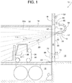
- An example lighting system 10 and associated methods shown in Figures 1 - 11 , comprises a lamp 12 for illuminating the interior of a vehicle 14 (e.g., a truck or trailer) parked at a loading dock 16 of a building 18.
- the lamp 12 is installed somewhere in relation to a doorway 20 and a dock leveler 22 that provides access between the vehicle 14 and the interior of the building 18.
- the lighting system 10 includes a motion sensing system 24 for determining whether a body 26 (e.g., a material handling device 28, person, etc.) is traveling farther into or out of the vehicle 14 and for providing an operation signal 30 indicating the body's travel direction.
- the lamp 12 is operatively connected in signal communication with the motion sensing system 24 so as to receive the operation signal 30 from the motion sensing system 24 and to dim or redirect the lamp's light output 32 when the body 26 is traveling toward the lamp 12
- the motion sensing system 24 is any component or system of components that detects the presence of a moving body or object that is spaced apart from the motion sensing system itself.
- Examples of the motion sensing system 24 include, but are not limited to, a video camera with analytics, a microphone with analytics, one or more photoelectric eyes, an ultrasonic sensor, a microwave sensor, a passive infrared sensor, a radar, etc.
- a controller 34 In response to the operation signal 30 indicating that the body 26 has undergone a change in travel direction, a controller 34 automatically switches the lamp 12 between a first illuminating mode and a second illuminating mode.
- first illuminating mode illustrated in Figures 1 and 3
- lamp projects more light (e.g., the light output 32a and 32c) toward the body 26 when the body 26 is traveling in a forward direction 36 farther into the vehicle 14.
- the lamp 12 projects less light (e.g., the light output 32b and 32d) toward the body 26 when the body 26 is traveling in a reverse direction 38 toward the lamp 12.
- the lamp 12 projects more lumens in the first illuminating mode ( Fig. 1 ) than in the second illuminating mode ( Fig. 2 ). In some examples, this is accomplished by providing the lamp 12 with a plurality of light-emitting elements 40 (e.g., light emitting diodes, LEDs, incandescent bulbs, fluorescent bulbs, etc.) and energizing more of them during the first illuminating mode than during the second illuminating mode. In addition or alternatively, more electrical power is delivered to one or more light-emitting elements 40 during the first illuminating mode than during the second illuminating mode.
- a plurality of light-emitting elements 40 e.g., light emitting diodes, LEDs, incandescent bulbs, fluorescent bulbs, etc.
- more electrical power is delivered to one or more light-emitting elements 40 during the first illuminating mode than during the second illuminating mode.
- the motion sensing system 24 comprises a Colibri universal motion sensor for automatic doors. Colibri motion sensors are provided by BEA sa (a HALMA company) of Angleur, Belgium.
- the lamp 12 comprises an array of six LEDs and optics (Cree XTE) provided by Cree of Durham, NC.
- the controller 34 may be implemented by a digital or analog electrical circuit, logic circuit and/or microprocessor with appropriate inputs and outputs for controlling the lamp 12 in response to input from motion sensing system 24. In some examples, at least part of the controller 34 is physically incorporated within the lamp 12.
- At least part of the controller 34 is housed within a mounting base 42 of the lamp 12. In some examples, at least part of the controller 34 is contained within a separate housing and is hardwired or connected in wireless communication with the lamp 12 and the motion sensing system 24. In some examples, the light-emitting elements 40 and the motion sensing system 24 are physically incorporated within the lamp 12 and share a common housing 12'.
- the lighting system's controller 34 includes a user adjustment input 44 to facilitate changing the brightness of the first and second illuminating modes.
- the user adjustment input 44 enables a user to vary the lamp's delta brightness between the first and second illuminating modes (e.g., correspondingly increasing or decreasing the brightness of the first and second modes by a common amount). Examples of user adjustment 44 include, but are not limited to, a potentiometer, a knob, a dial, a switch, a touchscreen and a pushbutton.
- the lamp 12 projects light output 32c as a high beam in a first direction 46 during the first illuminating mode ( Fig. 3 ) and projects light output 32d as a low beam in a second direction 48 during the second illuminating mode ( Fig. 4 ), wherein the first and second directions 46 and 48 deviate angularly.
- some examples of the motion sensing system 24 include a peripheral body sensor 52 (e.g., passive infrared sensor, ultrasonic sensor, microwave sensor, photoelectric eye, camera with video analytics, etc.).
- a peripheral body sensor 52 e.g., passive infrared sensor, ultrasonic sensor, microwave sensor, photoelectric eye, camera with video analytics, etc.
- the peripheral body 50 include, but are not limited to, a person, a material handling device, and a moving or stationary object.
- the peripheral body sensor 52 provides a warning signal 54 in response to sensing the presence or motion of the peripheral body 50 near the doorway 20.
- the lamp 12 is operatively connected in signal communication with the peripheral body sensor 52 so as to receive a warning signal 54.
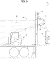
- the controller 32 switches the lamp 12 to a third illuminating mode, as shown in Figure 5 .
- the lamp 12 projects a warning light 56 into the vehicle 14.
- the warning light 56 of the third illuminating mode is distinguishable from the light projected during the first and second illuminating modes. Examples of the warning light 56 include, but are not limited to, a colored light, a flashing light, and a moving light.
- an articulated arm 58 connects the lamp 12 to the mounting base 42, which in turn is attached to a track 60 which, in the illustrated example, is fixed to the building 18.
- the base 42 mounted to the track 60 allows one to manually lower 62 the base 42 to where the adjustments can be done more readily.
- the person can return 64 the lamp 12 to its normally elevated position on the track 60.
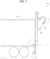
- the motion sensing system 24 provides a quiescent signal 66 in response to detecting a lack of motion for a threshold period of time inside the vehicle 14, as shown in Figure 7 . If the motion sensing system 24 fails to detect any appreciable motion over the threshold period of time (e.g., ten minutes), the lamp 12 turns off or provides a reduction of light output in response to the quiescent signal 66.
- a threshold period of time e.g., ten minutes
- some examples of the motion sensing system 24 comprise an enter/exit sensor 68 (e.g., two photoelectric eyes projecting two through-beams across the width of the doorway 20) that provides an enter-signal 70 in response to the body 26 (e.g., the material handling device 28) entering the vehicle 14 and providing an exit-signal 72 in response to the body 26 (e.g., the material handling device 28) exiting the vehicle 14.
- the sequence in which the two beams of the sensor 68 are interrupted indicates the direction in which the body 26 (e.g., the material handling device 28) is passing through the doorway 20.
- the signals 70 and 72 determining that the body 26 has just entered the vehicle 14 triggers the controller 34 to command the lamp 12 to operate in the first illuminating mode. In some examples, the signals 70 and 72 determining that the body 26 has entered the vehicle 14, in combination with detecting a lack of motion in vehicle 14 indicating that the body 26 is about to reverse direction, triggers the controller 34 to command the lamp 12 to switch from the first illuminating mode to the second illuminating mode.
- the articulated arm 58 comprises a plurality of links 74 interconnected via a plurality of pivotal joints 76.
- a fastener 78 e.g., a screw
- an adjustable degree of tightness provides means for adjusting the degree of tightness of the plurality of pivotal joints 76.
- a locking element 80 (e.g., a pin or screw) can be installed to lock a chosen joint 76a at a desired angle.
- Figure 8 shows the locking element 80 movable selectively to an installed position 82 for inhibiting the joint 76a from pivoting and a removed position 84 for providing the joint 76a with pivotal freedom.
- the lighting system 10 includes a powered actuator 85 connected to move the lamp 12 and the articulated arm 58 selectively between a stored position (e.g., Fig. 7 ) and a deployed position (e.g., Figs. 1 - 5 ).
- a stored position e.g., Fig. 7
- a deployed position e.g., Figs. 1 - 5
- the powered actuator 85 is operated automatically with the actuation of the door.
- the lamp 12 moves to the stored position when the door starts closing and moves to the deployed position when the door is fully open.
- Examples of the powered actuator 85 include, but are not limited to, an electric motor, a hydraulic motor, a pneumatic motor, a linear motor, a solenoid, a gear motor, and a hydraulic or pneumatic cylinder.
- the articulated arm 58 can be assembled in different configurations to define the arm's direction of pivotal freedom at each joint.
- Figure 9 shows a first link 74a rotated approximately ninety degrees relative to all the other links 74, including a second link 74b.
- the first link 74a is pivotal about a first axis 86
- the second link 74b is pivotal about a second axis 87.
- the first axis 86 is substantially perpendicular to the second axis 87.
- the first link 74a is inhibited from pivoting about a third axis 88 that is perpendicular to and intersecting the first axis 86.
- the second link 74b is inhibited from pivoting about a fourth axis 90 that is perpendicular to and intersecting the second axis 87.
- Block 94 represents projecting the light output 32 from the lamp 12.
- Block 96 represents sensing the body 26 moving relative to the lamp 12.
- Block 98 represents determining whether the body 26 is moving closer to or farther away from the lamp 12.
- Block 100 represents adjusting the light output 32.
- Figures 1 - 4 illustrate adjusting light output over a chosen range or delta of brightness. In some examples, the chosen range includes the range going from, but are not limited to, high to low beam, bright to dim, etc.
- Arrow 102 of Figure 8 represents adjusting the chosen range.
- Block 106 represents the body 26 (e.g., the material handling device 28) entering the vehicle 14.
- Block 108 represents sensing the body 26 (e.g., the material handling device 28) moving in the forward direction 36 farther into the vehicle 14.
- Block 110 represents sensing the body 26 (e.g., the material handling device 28) moving in the reverse direction 38.
- Block 112 represents the lamp 12 projecting more light in a primary direction 114 when the body 26 (e.g., the material handling device 28) is moving in the forward direction 36 farther into the vehicle 14 than when the body 26 (e.g., the material handling device 28) is moving in the reverse direction 38.
- Example lighting systems disclosed herein for use at a loading dock where a material handling device is used to load or unload a vehicle parked at the loading dock include a motion sensing system to be spaced apart from the material handling device.
- the motion sensing system of some examples is to provide an operation signal in response to the material handling device undergoing a change in travel direction within the vehicle.
- Some example lighting systems also include a lamp to be operatively connected in signal communication with the motion sensing system so as to receive the operation signal from the motion sensing system.
- the lamp has a first illuminating mode and a second illuminating mode, and the lamp is to switch between the first illuminating mode and the second illuminating mode in response to the operation signal.
- the change in travel direction pertains to the material handling device moving in a first direction farther into the vehicle and a second direction opposite the first direction.
- the lamp is to project more light when the lamp is in the first illuminating mode than when the lamp is in the second illuminating mode.
- the lamp includes a plurality of light-emitting elements. In some such examples, a greater number of the plurality of light-emitting elements are to emit light when the lamp is in the first illuminating mode than when the lamp is in the second illuminating mode.
- the lamp, in the first illuminating mode is to project light in a first direction and the lamp, in the second illuminating mode, is to project light in a second direction, the first direction being different from the second direction.
- the lighting system further includes a user adjustment input associated with the lamp.
- the user adjustment input in some such examples is to facilitate changing a brightness of the first illuminating mode and correspondingly changing a brightness of the second illuminating mode.
- the motion sensing system includes an enter/exit sensor to provide an enter-signal in response to the material handling device entering the vehicle and to provide an exit-signal in response to the material handling device exiting the vehicle.
- the motion sensing system is to provide a signal in response to the motion sensing system detecting a lack of motion over a threshold time period.
- the lamp is to reduce a light output in response to the signal.
- the motion sensing system is to include a peripheral body sensor positioned to sense a peripheral body beyond the vehicle.
- the peripheral body sensor in such examples is to provide a warning signal in response to sensing the peripheral body beyond the vehicle.
- the lamp is to be in signal communication with the peripheral body sensor so as to receive the warning signal from the peripheral body sensor.
- the lamp has a third illuminating mode distinguishable from the first illuminating mode and the second illuminating mode, and the lamp to switch to the third illuminating mode in response to the warning signal.
- the lighting system further includes an articulated arm to support the lamp.
- the articulated arm includes a plurality of links interconnected via a plurality of pivotal joints.
- Some example lighting systems also include a lock having an installed position and a removed position. In such examples, the lock in the removed position is to be spaced apart from the articulated arm and is to provide a first joint of the plurality of pivotal joints with pivotal freedom. In such examples, the lock in the installed position is to engage the articulated arm and is to inhibit pivotal motion of the first joint.
- the lighting system further includes an articulated arm to support the lamp. The articulated arm includes a plurality of links interconnected via a plurality of pivotal joints.
- the pivotal joints have an adjustable degree of tightness.
- the lighting system in some examples further includes fasteners at corresponding pivotal joints of the plurality of pivotal joints, the fastener to determine the degree of tightness of corresponding ones of the pivotal joints.
- the lighting system further includes an articulated arm to support the lamp, the articulated arm including a plurality of links interconnected via a plurality of pivotal joints.
- the plurality of links includes a first link pivotal about a first axis and a second link pivotal about a second axis. The first axis of some examples is substantially perpendicular to the second axis.
- the first link is inhibited from pivoting about a third axis perpendicular to and intersecting the first axis and the second link is inhibited from pivoting about a fourth axis perpendicular to and intersecting the second axis.
- the lighting system includes a track to be fixed to a wall of the loading dock and a base to be mounted to the track and vertically movable relative to the track.
- the lighting system also includes an articulated arm to couple the lamp to the base.
- the articulated arm includes a plurality of links interconnected via a plurality of pivotal joints.
- the lighting system includes an articulated arm to support the lamp.
- the articulated arm in some such examples includes a plurality of links interconnected via a plurality of pivotal joints.
- the lighting system also includes a powered actuator to be coupled to the articulated arm.
- the lamp and the articulated arm are to be selectively movable by the powered actuator to a stored position and a deployed position.
- the lamp includes a housing containing both a light-emitting element and the motion sensing system.
- Some example methods include projecting a light output from a lamp. Some example methods further include sensing a body moving relative to the lamp. Some example methods further include determining whether the body is moving closer to or farther away from the lamp. Some example methods also include adjusting the light output depending on whether the body is moving closer to or farther away from the lamp. Some such examples further include projecting more light when the body is moving farther away from the lamp than when the body is moving closer to the lamp. Some example methods also include aiming the light output higher when the body is moving farther away from the lamp than when the body is moving closer to the lamp. In some examples, the disclosed methods also include adjusting the light output over a chosen range; and adjusting the chosen range. Some example methods include sensing a lack of movement over a threshold period of time.
- the methods further include projecting more light when the body is moving farther away from the lamp than when the body is moving closer to the lamp. Some such example methods also include projecting more light when the body is moving closer to the lamp than when there is the lack of movement after the threshold period of time. Some example methods include projecting the light output into a vehicle. Some example methods further include sensing a peripheral body beyond the vehicle. In some such example methods also include, in response to sensing the peripheral body beyond the vehicle, projecting a warning light into the vehicle.
- Other example methods for use at a loading dock where a material handling device is used for transporting cargo relative to a vehicle parked at the loading dock include sensing the material handling device moving in a first direction farther into the vehicle. Some example methods further include sensing the material handling device moving in a second direction opposite the first direction. Some example methods further include projecting a light output from a lamp into the vehicle. In some examples, the lamp is spaced apart from the vehicle. In some examples, the lamp projects more light when the material handling device is moving in the first direction than when the material handling device is moving in the second direction.
- Some example methods further include aiming the light output higher when the material handling device is moving farther away from the lamp than when the material handling device is moving closer to the lamp. Some example methods further include sensing a lack of movement over a threshold period. Some example methods further include projecting more light when the material handling device is moving farther away from the lamp than when the material handling device is moving closer to the lamp. Some example methods further include projecting more light when the material handling device is moving closer to the lamp than when there is the lack of movement after the threshold period. Some example methods further include sensing a peripheral body beyond the vehicle. Some such example methods also include projecting a warning light into the vehicle.
Landscapes
- Engineering & Computer Science (AREA)
- Mechanical Engineering (AREA)
- General Engineering & Computer Science (AREA)
- Lighting Device Outwards From Vehicle And Optical Signal (AREA)
- Fittings On The Vehicle Exterior For Carrying Loads, And Devices For Holding Or Mounting Articles (AREA)
- Circuit Arrangement For Electric Light Sources In General (AREA)
- Arrangements Of Lighting Devices For Vehicle Interiors, Mounting And Supporting Thereof, Circuits Therefore (AREA)
Claims (13)
- Beleuchtungssystem für einen Ladeplatz, wo eine Material-Handhabungsvorrichtung (28) benutzt wird, um ein an dem Ladeplatz abgestelltes Fahrzeug zu beladen oder entladen, wobei das Beleuchtungssystem umfasst:ein von der Material-Handhabungsvorrichtung (28) beabstandetes bewegungserfassendes System (24), wobei das bewegungserfassende System (24) ein Betriebssignal in Antwort auf eine Bewegung der Material-Handhabungsvorrichtung (28) bereitstellt, undeine in Signalverbindung mit dem bewegungserfassenden System (24), um ein Betriebssignal von dem bewegungserfassenden System (24) zu empfangen, betriebsverbundene Leuchte (12),das bewegungserfassende System (24) ein Betriebssignal in Antwort auf ein Nachweisen eines Vollziehens einer Änderung in einer Bewegungsrichtung der Material-Handhabungsvorrichtung (28) innerhalb des Fahrzeugs zwischen einer Bewegung in eine Vorwärtsrichtung (36) weiter in das Fahrzeug und einer Bewegung in einer rückwärtigen Richtung (38) innerhalb des Fahrzeugs entgegengesetzt zu der Vorwärtsrichtung (36) bereitstellt,dadurch gekennzeichnet, dassdie Leuchte (12) das Innere des Fahrzeugs ausleuchtet und die Leuchte (12) in einen ersten Beleuchtungsmodus in Antwort auf das eine Bewegung der Material-Handhabungsvorrichtung (28) in der Vorwärtsrichtung (36) anzeigende Betriebssignal geschaltet wird und dass die Leuchte (12) in einen zweiten Beleuchtungsmodus in Antwort auf das eine Bewegung der Material-Handhabungsvorrichtung (28) in der rückwärtigen Richtung (38) anzeigende Betriebssignal geschaltet wird, wobei die Leuchte (12) angepasst ist, eine Lichtausgabe der Lampe herunterzuregeln oder umzuleiten, wenn die Leuchte (12) sich in dem zweiten Beleuchtungsmodus befindet.
- Beleuchtungssystem nach Anspruch 1, wobei die Leuchte (12) eine Vielzahl von Licht-emittierenden Elementen enthält, wobei eine größere Anzahl der Vielzahl von Licht-emittierenden Elementen Licht emittiert, wenn die Leuchte (12) sich in dem ersten Beleuchtungsmodus befindet, als, wenn sich die Leuchte in dem zweiten Beleuchtungsmodus befindet.
- Beleuchtungssystem nach Anspruch 1, wobei die Leuchte (12) in dem ersten Beleuchtungsmodus Licht in einem ersten Winkel auswirft, und wobei die Leuchte (12) in dem zweiten Beleuchtungsmodus Licht in einem zweiten Winkel auswirft, wobei der erste Winkel sich von dem zweiten Winkel unterscheidet.
- Beleuchtungssystem nach Anspruch 1 weiter umfassend einen mit der Leuchte (12) verbundenen Benutzer-Einstellungseingang, wobei der Benutzer-Einstellungseingang eine Änderung einer Helligkeit des ersten Beleuchtungsmodus und entsprechend eine Änderung einer Helligkeit des zweiten Beleuchtungsmodus möglich macht.
- Beleuchtungssystem nach Anspruch 1, wobei das bewegungserfassende System (24) einen Eingangs-/Ausgangs-Sensor enthält, um ein Eingangssignal in Antwort auf ein Eindringen der Material-Handhabungsvorrichtung (28) in das Fahrzeug bereitzustellen und ein Ausgangs-Signal in Antwort auf ein Verlassen des Fahrzeugs durch die Material-Handhabungsvorrichtung (28) bereitzustellen.
- Beleuchtungssystem nach Anspruch 1, wobei das bewegungserfassende System (24) ein Signal in Antwort auf ein Feststellen eines Fehlens einer Bewegung über eine Schwellwertdauer durch das bewegungserfassende System (24) bereitstellt, wobei die Leuchte (12) eine Lichtausgabe in Antwort auf das Signal verringert.
- Beleuchtungssystem nach Anspruch 1, wobei das bewegungserfassende System (24) einen zum Erfassen eines Körperumfangs jenseits des Fahrzeugs positionierten Körperumfangs-Sensor enthält, wobei der Körperumfangs-Sensor ein Warnsignal in Antwort auf ein Erfassen des Körperumfangs jenseits des Fahrzeugs bereitstellt, wobei die Leuchte (12) in einer Signalverbindung mit dem Körperumfangs-Sensor ist, um das Warnsignal von dem Körperumfangs-Sensor zu empfangen, wobei die Leuchte (12) einen dritten, von dem ersten und zweiten Beleuchtungsmodus unterscheidbaren Beleuchtungsmodus aufweist und die Leuchte (12) in Antwort auf das Warnsignal in den dritten Beleuchtungsmodus schaltet.
- Beleuchtungssystem nach Anspruch 1 weiter umfassend:einen Gelenkarm (58) zum Halten der Leuchte (12), wobei der Gelenkarm (58) eine Vielzahl von über eine Vielzahl von Drehgelenken miteinander verbundenen Verbindungsgliedern umfasst, undeinen Riegel (80) mit einer eingerichteten Position und einer entfernten Position, wobei der Riegel (80) in der entfernten Position von dem Gelenkarm (58) beabstandet ist und einem ersten Verbindungsglied der Vielzahl von Verbindungsgliedern eine Drehfreiheit bereitstellt, wobei der Riegel (80) in der eingerichteten Position in den Gelenkarm (58) eingreift und eine Drehbewegung des ersten Verbindungsglieds verhindert.
- Beleuchtungssystem nach Anspruch 1 weiter umfassend:einen Gelenkarm (58) zum Halten der Leuchte (12), wobei der Gelenkarm (58) eine Vielzahl von über eine Vielzahl von Drehgelenken miteinander verbundenen Verbindungsgliedern umfasst, wobei die Drehgelenke einen einstellbaren Grad an Festigkeit aufweisen undBefestigungsmittel (78) an entsprechenden Drehgelenken der Vielzahl von Drehgelenken, wobei die Befestigungsmittel (78) den Grad an Festigkeit der entsprechenden der Drehgelenke bestimmen.
- Beleuchtungssystem nach Anspruch 1 weiter umfassend:
einen Gelenkarm (58), um die Leuchte (12) zu halten, wobei der Gelenkarm (58) eine Vielzahl von über eine Vielzahl von Drehgelenken miteinander verbundenen Verbindungsgliedern umfasst, wobei die Vielzahl von Verbindungsgliedern ein erstes um eine erste Achse drehbares Verbindungsglied und ein zweites um eine zweite Achse drehbares Verbindungsgelenk enthält, wobei die erste Achse im Wesentlichen senkrecht zu der zweiten Achse ist, wobei das erste Verbindungsglied an einer Drehung um eine dritte, zu der ersten Achse senkrechte und die erste Achse schneidende Achse gehindert wird, wobei das zweite Verbindungsglied an einer Drehung um eine vierte, zu der zweiten Achse senkrechte und die zweite Achse schneidende Achse gehindert wird. - Beleuchtungssystem nach Anspruch 1 weiter umfassend:eine an einer Wand des Ladeplatzes angebrachte Führungsbahn (60),eine an der Führungsbahn (60) befestigte und vertikal relativ zu der Führungsbahn (60) bewegliche Basis (42) undeinen Gelenkarm (58) zum Verbinden der Leuchte (12) mit der Basis, wobei der Gelenkarm (58) eine Vielzahl von über eine Vielzahl von Drehgelenken verbundenen Verbindungsgliedern umfasst.
- Beleuchtungssystem nach Anspruch 1 weiter umfassend:einen Gelenkarm (58) zum Halten der Leuchte (12), wobei der Gelenkarm (58) eine Vielzahl von über eine Vielzahl von Drehgelenken miteinander verbundenen Verbindungsgliedern umfasst, undeinen angetriebenen, mit dem Gelenkarm (58) verbundenen Aktuator, wobei die Leuchte (12) und der Gelenkarm (58) selektiv von dem angetriebenen Aktuator in eine gespeicherte Position und eine eingesetzte Position bewegbar sind.
- Beleuchtungssystem nach Anspruch 1, wobei die Leuchte (12) ein sowohl ein Licht-emittierendes Element als auch das bewegungserfassende System (24) beinhaltendes Gehäuse enthält.
Priority Applications (1)
| Application Number | Priority Date | Filing Date | Title |
|---|---|---|---|
| EP18169951.3A EP3373706B1 (de) | 2013-02-08 | 2014-01-29 | Bewegungserfassende rampenbeleuchtungssysteme |
Applications Claiming Priority (2)
| Application Number | Priority Date | Filing Date | Title |
|---|---|---|---|
| US13/762,916 US9255699B2 (en) | 2013-02-08 | 2013-02-08 | Motion sensing dock lighting systems |
| PCT/US2014/013494 WO2014123733A1 (en) | 2013-02-08 | 2014-01-29 | Motion sensing dock lighting systems |
Related Child Applications (1)
| Application Number | Title | Priority Date | Filing Date |
|---|---|---|---|
| EP18169951.3A Division EP3373706B1 (de) | 2013-02-08 | 2014-01-29 | Bewegungserfassende rampenbeleuchtungssysteme |
Publications (2)
| Publication Number | Publication Date |
|---|---|
| EP2954754A1 EP2954754A1 (de) | 2015-12-16 |
| EP2954754B1 true EP2954754B1 (de) | 2018-05-02 |
Family
ID=50185007
Family Applications (2)
| Application Number | Title | Priority Date | Filing Date |
|---|---|---|---|
| EP18169951.3A Active EP3373706B1 (de) | 2013-02-08 | 2014-01-29 | Bewegungserfassende rampenbeleuchtungssysteme |
| EP14706995.9A Active EP2954754B1 (de) | 2013-02-08 | 2014-01-29 | Bewegungserfassende rampenbeleuchtungssysteme |
Family Applications Before (1)
| Application Number | Title | Priority Date | Filing Date |
|---|---|---|---|
| EP18169951.3A Active EP3373706B1 (de) | 2013-02-08 | 2014-01-29 | Bewegungserfassende rampenbeleuchtungssysteme |
Country Status (10)
| Country | Link |
|---|---|
| US (1) | US9255699B2 (de) |
| EP (2) | EP3373706B1 (de) |
| CN (2) | CN107277987B (de) |
| AU (1) | AU2014215676B2 (de) |
| BR (1) | BR112015019076B1 (de) |
| CA (2) | CA3027623C (de) |
| DK (1) | DK2954754T3 (de) |
| ES (1) | ES2676226T3 (de) |
| MX (1) | MX347926B (de) |
| WO (1) | WO2014123733A1 (de) |
Families Citing this family (29)
| Publication number | Priority date | Publication date | Assignee | Title |
|---|---|---|---|---|
| US9255699B2 (en) | 2013-02-08 | 2016-02-09 | Rite-Hite Holding Corporation | Motion sensing dock lighting systems |
| US9726359B1 (en) * | 2014-02-27 | 2017-08-08 | Hkc-Us, Llc | Light fixture including adjustable motion sensor with rectangular coverage pattern |
| CN106458480B (zh) | 2014-05-02 | 2019-03-26 | 亚萨合莱自动门系统有限公司 | 用于自动控制装卸月台设备的系统及方法 |
| US9926148B2 (en) * | 2014-06-27 | 2018-03-27 | Rite-Hite Holding Corporation | Pedestrian-vehicle safety systems for loading docks |
| AU2016205036B2 (en) * | 2015-01-09 | 2019-12-19 | J.W. Speaker Corporation | Tracking and lighting systems and methods for a vehicle |
| US9771225B2 (en) | 2015-10-08 | 2017-09-26 | Rite-Hite Holding Corporation | Methods and apparatus for monitoring a loading dock |
| US10781062B2 (en) | 2015-11-24 | 2020-09-22 | Systems, LLC | Vehicle restraint system |
| US11305953B2 (en) | 2016-05-03 | 2022-04-19 | Assa Abloy Entrance Systems Ab | Control systems for operation of loading dock equipment, and associated methods of manufacture and use |
| US9896282B2 (en) * | 2016-05-27 | 2018-02-20 | Rite-Hite Holding Corporation | Pedestrian-vehicle warning systems for loading docks |
| US10906759B2 (en) | 2017-06-28 | 2021-02-02 | Systems, LLC | Loading dock vehicle restraint system |
| US10745220B2 (en) | 2017-06-28 | 2020-08-18 | Systems, LLC | Vehicle Restraint System |
| US11256264B2 (en) | 2017-08-30 | 2022-02-22 | Assa Abloy Entrance Systems Ab | Vehicle guidance systems and associated methods of use at logistics yards and other locations |
| US10302295B2 (en) | 2017-10-18 | 2019-05-28 | Rite-Hite Holding Corporation | Illuminating fans for loading docks |
| EP3762321A2 (de) | 2018-03-09 | 2021-01-13 | Rite-Hite Holding Corporation | Verfahren und vorrichtung zur überwachung und verwaltung von ladedocks und anlagenoperationen |
| US20190333349A1 (en) * | 2018-04-25 | 2019-10-31 | Dong Guan Bright Yinhuey Lighting Co., Ltd. China | Illuminating Device With Monitoring Alarm Function |
| US10494205B1 (en) | 2018-12-06 | 2019-12-03 | Assa Abloy Entrance Systems Ab | Remote loading dock authorization systems and methods |
| US11142413B2 (en) | 2019-01-28 | 2021-10-12 | Assa Abloy Entrance Systems Ab | Systems and methods for automated loading and unloading at a dock station |
| CA201546S (en) | 2019-03-08 | 2022-01-28 | Rite Hite Holding Corp | Mounting device for fan and light |
| USD933283S1 (en) | 2019-08-28 | 2021-10-12 | Rite-Hite Holding Corporation | Fan and light mounting system |
| US11299088B2 (en) * | 2019-05-17 | 2022-04-12 | Deere & Company | Adaptive work vehicle lighting system and method of adaptively illuminating a work area |
| USD907842S1 (en) | 2019-06-04 | 2021-01-12 | Tri Lite, Inc. | Dock light arm |
| US11236873B2 (en) | 2019-06-04 | 2022-02-01 | Tri Lite, Inc. | Dock light apparatus |
| US11262747B2 (en) | 2019-06-11 | 2022-03-01 | Assa Abloy Entrance Systems Ab | Vehicle identification and guidance systems and associated methods |
| US10969093B1 (en) * | 2020-01-20 | 2021-04-06 | Dong Guan Jia Sheng Lighting Technology Co., Ltd. China | Rotatable lamp and two cameras for detecting movement |
| US11858311B2 (en) * | 2020-04-29 | 2024-01-02 | Walmart Apollo, PLLC | Environmental control device mounting frame |
| CN111629473B (zh) * | 2020-06-05 | 2021-12-28 | 连云港杰瑞电子有限公司 | 一种港口照明智能控制系统及方法 |
| US12570129B2 (en) | 2021-06-02 | 2026-03-10 | Assa Abloy Entrance Systems Ab | Loading dock automated trailer door systems |
| WO2023274744A2 (en) | 2021-07-02 | 2023-01-05 | Assa Abloy Entrance Systems Ab | Powered trailer systems |
| US12400175B2 (en) | 2021-11-30 | 2025-08-26 | Assa Abloy Entrance Systems Ab | Trailer validation systems |
Family Cites Families (44)
| Publication number | Priority date | Publication date | Assignee | Title |
|---|---|---|---|---|
| US2538655A (en) | 1947-05-05 | 1951-01-16 | Ralph G Preston | Loader's extensible light fixture |
| FR1304682A (fr) | 1961-07-27 | 1962-09-28 | Dispositif d'éclairage permettant d'observer des cavités étroites et profondes | |
| US3275878A (en) | 1963-02-27 | 1966-09-27 | Tektronix Inc | Lead-in seal for evacuated envelope of an electron discharge device for connecting electrodes located within said envelope to a voltage source positioned outside said envelope |
| USD296369S (en) | 1984-09-12 | 1988-06-21 | Manville Corporation | Luminaire |
| US4973016A (en) | 1989-07-24 | 1990-11-27 | Patton Electric Company, Inc. | Dock fan and light cantilever-mounted articulated multi-arm utility support assembly |
| USD327131S (en) | 1989-12-28 | 1992-06-16 | North American Philips Corporation | Reflector lamp |
| US5171086A (en) | 1991-03-22 | 1992-12-15 | Baloochi Mohsen K | Hand held adjustable focus flash light |
| US6445884B1 (en) * | 1995-06-22 | 2002-09-03 | 3Dv Systems, Ltd. | Camera with through-the-lens lighting |
| EP0799977B1 (de) * | 1996-04-04 | 2000-12-13 | Toyota Jidosha Kabushiki Kaisha | Variable Ventilzeitsteuervorrichtung für Brennkraftmaschine |
| US5709458A (en) | 1996-08-14 | 1998-01-20 | Metz; Donald | Dock light |
| JP2000042970A (ja) * | 1998-07-31 | 2000-02-15 | Kobe Steel Ltd | 多関節アーム式搬送装置 |
| GR1003642B (el) | 2000-11-21 | 2001-08-22 | Τεντααμεακρυφοαχωνευτοαφωτισμο.α | |
| JP4628602B2 (ja) * | 2001-04-05 | 2011-02-09 | ナブテスコ株式会社 | ロボットアーム |
| US20030067767A1 (en) | 2001-10-10 | 2003-04-10 | Daniel Liu | Portable energy-saving lighting device |
| US20050168999A1 (en) | 2004-02-03 | 2005-08-04 | Gelcore Llc | LED light for loading dock |
| US20050260943A1 (en) | 2004-05-21 | 2005-11-24 | Snyder Ronald P | Loading dock fan |
| US8590087B2 (en) | 2004-12-14 | 2013-11-26 | Rite-Hite Holding Corporation | Lighting and signaling systems for loading docks |
| CN101384205B (zh) * | 2006-02-13 | 2012-12-12 | 布莱克和戴克尔公司 | 带有可露出的板刷的电动拖把 |
| USD549854S1 (en) | 2006-05-24 | 2007-08-28 | Toshiba Lighting & Technology Corporation | Light emitting diode lamp |
| USD542943S1 (en) | 2006-05-30 | 2007-05-15 | Augux Co. Ltd. | LED lamp |
| US7533431B2 (en) * | 2006-07-11 | 2009-05-19 | Rite-Hite Holding Corporation | Illuminating dock leveler |
| USD546980S1 (en) | 2006-10-25 | 2007-07-17 | Hsin-Chih Chung Lee | LED bulb |
| CA2692187A1 (en) | 2007-06-29 | 2009-01-08 | Carmanah Technologies Corp. | Intelligent area lighting system |
| USD566300S1 (en) | 2007-10-18 | 2008-04-08 | Hsin-Chih Chung Lee | LED bulb |
| WO2009087261A1 (es) * | 2008-01-10 | 2009-07-16 | Roberto Ponticelli Lima | Dispositivo pasa-páginas automático que emplea un brazo articulado mecatrónico |
| AU322403S (en) | 2008-02-13 | 2008-12-01 | Osram Gmbh | Lamp |
| US7967549B2 (en) * | 2008-05-15 | 2011-06-28 | The Boeing Company | Robotic system including foldable robotic arm |
| USD582578S1 (en) | 2008-05-15 | 2008-12-09 | Edison Opto Corporation | Light emitting diode light bulb |
| USD599931S1 (en) | 2008-06-02 | 2009-09-08 | Koninklijke Philips Electronics N.V. | Luminaire |
| CN201313754Y (zh) * | 2008-12-12 | 2009-09-23 | 上海海联润滑材料科技有限公司 | 车载滑车 |
| JP4829991B2 (ja) * | 2009-03-23 | 2011-12-07 | シャープ株式会社 | 自動調光システム |
| US8536802B2 (en) | 2009-04-14 | 2013-09-17 | Digital Lumens Incorporated | LED-based lighting methods, apparatus, and systems employing LED light bars, occupancy sensing, and local state machine |
| DE102009031732B3 (de) * | 2009-07-04 | 2010-11-25 | Sick Ag | Entfernungsmessender optoelektronischer Sensor |
| JP2011026887A (ja) * | 2009-07-28 | 2011-02-10 | Hiroshi Onodera | 杭引抜き用作業機 |
| US20110203059A1 (en) | 2010-02-22 | 2011-08-25 | 4Front Engineered Solutions, Inc. | Loading dock lighting systems having warning features |
| TWI425182B (zh) * | 2010-06-15 | 2014-02-01 | Pixart Imaging Inc | 距離測量系統及其方法 |
| EP2428471B1 (de) * | 2010-09-08 | 2013-06-05 | Krones AG | Fördersystem |
| USD664272S1 (en) | 2011-03-04 | 2012-07-24 | Techwon Co., Ltd. | LED lamp |
| USD647646S1 (en) | 2011-05-10 | 2011-10-25 | Applied Lighting Company | LED lamp |
| USD683883S1 (en) | 2012-05-04 | 2013-06-04 | Lighting Science Group Corporation | Light fixture adapted to interface with a wall structure |
| USD702397S1 (en) | 2013-02-08 | 2014-04-08 | Rite-Hite Holding Corporation | Link for an articulated arm of a light fixture |
| US9255699B2 (en) | 2013-02-08 | 2016-02-09 | Rite-Hite Holding Corporation | Motion sensing dock lighting systems |
| USD693947S1 (en) | 2013-02-08 | 2013-11-19 | Rite-Hite Holding Corporation | Lamp head for light fixtures |
| USD701640S1 (en) | 2013-04-10 | 2014-03-25 | Rite-Hite Holding Corporation | Link for an articulated arm of a light fixture |
-
2013
- 2013-02-08 US US13/762,916 patent/US9255699B2/en active Active
-
2014
- 2014-01-29 CA CA3027623A patent/CA3027623C/en active Active
- 2014-01-29 BR BR112015019076-6A patent/BR112015019076B1/pt not_active IP Right Cessation
- 2014-01-29 CN CN201710378306.4A patent/CN107277987B/zh active Active
- 2014-01-29 AU AU2014215676A patent/AU2014215676B2/en active Active
- 2014-01-29 WO PCT/US2014/013494 patent/WO2014123733A1/en not_active Ceased
- 2014-01-29 DK DK14706995.9T patent/DK2954754T3/da active
- 2014-01-29 ES ES14706995.9T patent/ES2676226T3/es active Active
- 2014-01-29 CN CN201480007856.XA patent/CN104969661B/zh active Active
- 2014-01-29 EP EP18169951.3A patent/EP3373706B1/de active Active
- 2014-01-29 MX MX2015009406A patent/MX347926B/es active IP Right Grant
- 2014-01-29 EP EP14706995.9A patent/EP2954754B1/de active Active
- 2014-01-29 CA CA2898859A patent/CA2898859C/en active Active
Non-Patent Citations (1)
| Title |
|---|
| None * |
Also Published As
| Publication number | Publication date |
|---|---|
| CN104969661B (zh) | 2017-06-20 |
| CN104969661A (zh) | 2015-10-07 |
| CA2898859C (en) | 2018-12-18 |
| EP3373706A1 (de) | 2018-09-12 |
| DK2954754T3 (da) | 2018-07-16 |
| EP2954754A1 (de) | 2015-12-16 |
| MX347926B (es) | 2017-05-18 |
| BR112015019076B1 (pt) | 2022-01-18 |
| AU2014215676B2 (en) | 2016-07-07 |
| MX2015009406A (es) | 2016-02-18 |
| CA3027623A1 (en) | 2014-08-14 |
| US9255699B2 (en) | 2016-02-09 |
| EP3373706B1 (de) | 2019-12-18 |
| AU2014215676A1 (en) | 2015-08-06 |
| BR112015019076A2 (pt) | 2017-07-18 |
| ES2676226T3 (es) | 2018-07-17 |
| CA2898859A1 (en) | 2014-08-14 |
| WO2014123733A1 (en) | 2014-08-14 |
| US20140225509A1 (en) | 2014-08-14 |
| CN107277987A (zh) | 2017-10-20 |
| CA3027623C (en) | 2020-12-15 |
| CN107277987B (zh) | 2020-03-10 |
Similar Documents
| Publication | Publication Date | Title |
|---|---|---|
| EP3373706B1 (de) | Bewegungserfassende rampenbeleuchtungssysteme | |
| AU2007272681B2 (en) | Illuminating dock leveler | |
| US20110203059A1 (en) | Loading dock lighting systems having warning features | |
| US20080124203A1 (en) | Integrated vehicle docking system and related method | |
| EP2634120B1 (de) | Erweiterbare Förderanlage mit Beleuchtung | |
| CA2657374C (en) | Illuminated loading dock system | |
| EP3177798B1 (de) | Türsysteme zur anzeige des zustandes von türoperationen | |
| US6690287B2 (en) | Warning sign system for entering and exiting garage doors and entrances | |
| US8590087B2 (en) | Lighting and signaling systems for loading docks | |
| CN109311609B (zh) | 用于装载月台的行人车辆警告系统 | |
| US20060051196A1 (en) | Integrated vehicle docking system and related method | |
| DK3061713T3 (en) | Loading station with loading port and loading ramp | |
| KR20260065014A (ko) | 호이스트 | |
| JP2025163370A (ja) | 柵部材開閉装置 | |
| JP2000016143A (ja) | トラック用移動荷役装置の衝立移動制御システム |
Legal Events
| Date | Code | Title | Description |
|---|---|---|---|
| PUAI | Public reference made under article 153(3) epc to a published international application that has entered the european phase |
Free format text: ORIGINAL CODE: 0009012 |
|
| 17P | Request for examination filed |
Effective date: 20150722 |
|
| AK | Designated contracting states |
Kind code of ref document: A1 Designated state(s): AL AT BE BG CH CY CZ DE DK EE ES FI FR GB GR HR HU IE IS IT LI LT LU LV MC MK MT NL NO PL PT RO RS SE SI SK SM TR |
|
| AX | Request for extension of the european patent |
Extension state: BA ME |
|
| DAX | Request for extension of the european patent (deleted) | ||
| 17Q | First examination report despatched |
Effective date: 20160720 |
|
| STAA | Information on the status of an ep patent application or granted ep patent |
Free format text: STATUS: EXAMINATION IS IN PROGRESS |
|
| REG | Reference to a national code |
Ref country code: DE Ref legal event code: R079 Ref document number: 602014024812 Country of ref document: DE Free format text: PREVIOUS MAIN CLASS: H05B0037000000 Ipc: B65G0069280000 |
|
| GRAP | Despatch of communication of intention to grant a patent |
Free format text: ORIGINAL CODE: EPIDOSNIGR1 |
|
| STAA | Information on the status of an ep patent application or granted ep patent |
Free format text: STATUS: GRANT OF PATENT IS INTENDED |
|
| RIC1 | Information provided on ipc code assigned before grant |
Ipc: B65G 69/28 20060101AFI20171025BHEP Ipc: H05B 37/02 20060101ALI20171025BHEP Ipc: F21V 21/26 20060101ALI20171025BHEP |
|
| INTG | Intention to grant announced |
Effective date: 20171116 |
|
| GRAS | Grant fee paid |
Free format text: ORIGINAL CODE: EPIDOSNIGR3 |
|
| GRAA | (expected) grant |
Free format text: ORIGINAL CODE: 0009210 |
|
| STAA | Information on the status of an ep patent application or granted ep patent |
Free format text: STATUS: THE PATENT HAS BEEN GRANTED |
|
| AK | Designated contracting states |
Kind code of ref document: B1 Designated state(s): AL AT BE BG CH CY CZ DE DK EE ES FI FR GB GR HR HU IE IS IT LI LT LU LV MC MK MT NL NO PL PT RO RS SE SI SK SM TR |
|
| REG | Reference to a national code |
Ref country code: GB Ref legal event code: FG4D |
|
| REG | Reference to a national code |
Ref country code: CH Ref legal event code: EP Ref country code: AT Ref legal event code: REF Ref document number: 994997 Country of ref document: AT Kind code of ref document: T Effective date: 20180515 |
|
| REG | Reference to a national code |
Ref country code: DE Ref legal event code: R096 Ref document number: 602014024812 Country of ref document: DE |
|
| REG | Reference to a national code |
Ref country code: IE Ref legal event code: FG4D |
|
| REG | Reference to a national code |
Ref country code: DK Ref legal event code: T3 Effective date: 20180711 |
|
| REG | Reference to a national code |
Ref country code: ES Ref legal event code: FG2A Ref document number: 2676226 Country of ref document: ES Kind code of ref document: T3 Effective date: 20180717 |
|
| REG | Reference to a national code |
Ref country code: NL Ref legal event code: FP |
|
| REG | Reference to a national code |
Ref country code: LT Ref legal event code: MG4D |
|
| PG25 | Lapsed in a contracting state [announced via postgrant information from national office to epo] |
Ref country code: SE Free format text: LAPSE BECAUSE OF FAILURE TO SUBMIT A TRANSLATION OF THE DESCRIPTION OR TO PAY THE FEE WITHIN THE PRESCRIBED TIME-LIMIT Effective date: 20180502 Ref country code: LT Free format text: LAPSE BECAUSE OF FAILURE TO SUBMIT A TRANSLATION OF THE DESCRIPTION OR TO PAY THE FEE WITHIN THE PRESCRIBED TIME-LIMIT Effective date: 20180502 Ref country code: FI Free format text: LAPSE BECAUSE OF FAILURE TO SUBMIT A TRANSLATION OF THE DESCRIPTION OR TO PAY THE FEE WITHIN THE PRESCRIBED TIME-LIMIT Effective date: 20180502 Ref country code: BG Free format text: LAPSE BECAUSE OF FAILURE TO SUBMIT A TRANSLATION OF THE DESCRIPTION OR TO PAY THE FEE WITHIN THE PRESCRIBED TIME-LIMIT Effective date: 20180802 Ref country code: NO Free format text: LAPSE BECAUSE OF FAILURE TO SUBMIT A TRANSLATION OF THE DESCRIPTION OR TO PAY THE FEE WITHIN THE PRESCRIBED TIME-LIMIT Effective date: 20180802 |
|
| PG25 | Lapsed in a contracting state [announced via postgrant information from national office to epo] |
Ref country code: GR Free format text: LAPSE BECAUSE OF FAILURE TO SUBMIT A TRANSLATION OF THE DESCRIPTION OR TO PAY THE FEE WITHIN THE PRESCRIBED TIME-LIMIT Effective date: 20180803 Ref country code: LV Free format text: LAPSE BECAUSE OF FAILURE TO SUBMIT A TRANSLATION OF THE DESCRIPTION OR TO PAY THE FEE WITHIN THE PRESCRIBED TIME-LIMIT Effective date: 20180502 Ref country code: HR Free format text: LAPSE BECAUSE OF FAILURE TO SUBMIT A TRANSLATION OF THE DESCRIPTION OR TO PAY THE FEE WITHIN THE PRESCRIBED TIME-LIMIT Effective date: 20180502 Ref country code: RS Free format text: LAPSE BECAUSE OF FAILURE TO SUBMIT A TRANSLATION OF THE DESCRIPTION OR TO PAY THE FEE WITHIN THE PRESCRIBED TIME-LIMIT Effective date: 20180502 |
|
| REG | Reference to a national code |
Ref country code: AT Ref legal event code: MK05 Ref document number: 994997 Country of ref document: AT Kind code of ref document: T Effective date: 20180502 |
|
| PG25 | Lapsed in a contracting state [announced via postgrant information from national office to epo] |
Ref country code: PL Free format text: LAPSE BECAUSE OF FAILURE TO SUBMIT A TRANSLATION OF THE DESCRIPTION OR TO PAY THE FEE WITHIN THE PRESCRIBED TIME-LIMIT Effective date: 20180502 Ref country code: RO Free format text: LAPSE BECAUSE OF FAILURE TO SUBMIT A TRANSLATION OF THE DESCRIPTION OR TO PAY THE FEE WITHIN THE PRESCRIBED TIME-LIMIT Effective date: 20180502 Ref country code: SK Free format text: LAPSE BECAUSE OF FAILURE TO SUBMIT A TRANSLATION OF THE DESCRIPTION OR TO PAY THE FEE WITHIN THE PRESCRIBED TIME-LIMIT Effective date: 20180502 Ref country code: AT Free format text: LAPSE BECAUSE OF FAILURE TO SUBMIT A TRANSLATION OF THE DESCRIPTION OR TO PAY THE FEE WITHIN THE PRESCRIBED TIME-LIMIT Effective date: 20180502 Ref country code: EE Free format text: LAPSE BECAUSE OF FAILURE TO SUBMIT A TRANSLATION OF THE DESCRIPTION OR TO PAY THE FEE WITHIN THE PRESCRIBED TIME-LIMIT Effective date: 20180502 |
|
| REG | Reference to a national code |
Ref country code: DE Ref legal event code: R097 Ref document number: 602014024812 Country of ref document: DE |
|
| PG25 | Lapsed in a contracting state [announced via postgrant information from national office to epo] |
Ref country code: SM Free format text: LAPSE BECAUSE OF FAILURE TO SUBMIT A TRANSLATION OF THE DESCRIPTION OR TO PAY THE FEE WITHIN THE PRESCRIBED TIME-LIMIT Effective date: 20180502 |
|
| PLBE | No opposition filed within time limit |
Free format text: ORIGINAL CODE: 0009261 |
|
| STAA | Information on the status of an ep patent application or granted ep patent |
Free format text: STATUS: NO OPPOSITION FILED WITHIN TIME LIMIT |
|
| 26N | No opposition filed |
Effective date: 20190205 |
|
| PG25 | Lapsed in a contracting state [announced via postgrant information from national office to epo] |
Ref country code: SI Free format text: LAPSE BECAUSE OF FAILURE TO SUBMIT A TRANSLATION OF THE DESCRIPTION OR TO PAY THE FEE WITHIN THE PRESCRIBED TIME-LIMIT Effective date: 20180502 |
|
| PG25 | Lapsed in a contracting state [announced via postgrant information from national office to epo] |
Ref country code: MC Free format text: LAPSE BECAUSE OF FAILURE TO SUBMIT A TRANSLATION OF THE DESCRIPTION OR TO PAY THE FEE WITHIN THE PRESCRIBED TIME-LIMIT Effective date: 20180502 |
|
| REG | Reference to a national code |
Ref country code: CH Ref legal event code: PL |
|
| PG25 | Lapsed in a contracting state [announced via postgrant information from national office to epo] |
Ref country code: LU Free format text: LAPSE BECAUSE OF NON-PAYMENT OF DUE FEES Effective date: 20190129 |
|
| REG | Reference to a national code |
Ref country code: BE Ref legal event code: MM Effective date: 20190131 |
|
| PG25 | Lapsed in a contracting state [announced via postgrant information from national office to epo] |
Ref country code: AL Free format text: LAPSE BECAUSE OF FAILURE TO SUBMIT A TRANSLATION OF THE DESCRIPTION OR TO PAY THE FEE WITHIN THE PRESCRIBED TIME-LIMIT Effective date: 20180502 Ref country code: BE Free format text: LAPSE BECAUSE OF NON-PAYMENT OF DUE FEES Effective date: 20190131 |
|
| PG25 | Lapsed in a contracting state [announced via postgrant information from national office to epo] |
Ref country code: LI Free format text: LAPSE BECAUSE OF NON-PAYMENT OF DUE FEES Effective date: 20190131 Ref country code: CH Free format text: LAPSE BECAUSE OF NON-PAYMENT OF DUE FEES Effective date: 20190131 |
|
| PG25 | Lapsed in a contracting state [announced via postgrant information from national office to epo] |
Ref country code: TR Free format text: LAPSE BECAUSE OF FAILURE TO SUBMIT A TRANSLATION OF THE DESCRIPTION OR TO PAY THE FEE WITHIN THE PRESCRIBED TIME-LIMIT Effective date: 20180502 |
|
| PG25 | Lapsed in a contracting state [announced via postgrant information from national office to epo] |
Ref country code: MT Free format text: LAPSE BECAUSE OF NON-PAYMENT OF DUE FEES Effective date: 20190129 Ref country code: PT Free format text: LAPSE BECAUSE OF FAILURE TO SUBMIT A TRANSLATION OF THE DESCRIPTION OR TO PAY THE FEE WITHIN THE PRESCRIBED TIME-LIMIT Effective date: 20180903 |
|
| PG25 | Lapsed in a contracting state [announced via postgrant information from national office to epo] |
Ref country code: CY Free format text: LAPSE BECAUSE OF FAILURE TO SUBMIT A TRANSLATION OF THE DESCRIPTION OR TO PAY THE FEE WITHIN THE PRESCRIBED TIME-LIMIT Effective date: 20180502 |
|
| PG25 | Lapsed in a contracting state [announced via postgrant information from national office to epo] |
Ref country code: IS Free format text: LAPSE BECAUSE OF FAILURE TO SUBMIT A TRANSLATION OF THE DESCRIPTION OR TO PAY THE FEE WITHIN THE PRESCRIBED TIME-LIMIT Effective date: 20180902 |
|
| PG25 | Lapsed in a contracting state [announced via postgrant information from national office to epo] |
Ref country code: HU Free format text: LAPSE BECAUSE OF FAILURE TO SUBMIT A TRANSLATION OF THE DESCRIPTION OR TO PAY THE FEE WITHIN THE PRESCRIBED TIME-LIMIT; INVALID AB INITIO Effective date: 20140129 |
|
| PG25 | Lapsed in a contracting state [announced via postgrant information from national office to epo] |
Ref country code: MK Free format text: LAPSE BECAUSE OF FAILURE TO SUBMIT A TRANSLATION OF THE DESCRIPTION OR TO PAY THE FEE WITHIN THE PRESCRIBED TIME-LIMIT Effective date: 20180502 |
|
| PGFP | Annual fee paid to national office [announced via postgrant information from national office to epo] |
Ref country code: GB Payment date: 20251211 Year of fee payment: 13 |
|
| PGFP | Annual fee paid to national office [announced via postgrant information from national office to epo] |
Ref country code: NL Payment date: 20251215 Year of fee payment: 13 Ref country code: FR Payment date: 20251208 Year of fee payment: 13 |
|
| PGFP | Annual fee paid to national office [announced via postgrant information from national office to epo] |
Ref country code: IE Payment date: 20251209 Year of fee payment: 13 |
|
| PGFP | Annual fee paid to national office [announced via postgrant information from national office to epo] |
Ref country code: ES Payment date: 20260212 Year of fee payment: 13 |
|
| PGFP | Annual fee paid to national office [announced via postgrant information from national office to epo] |
Ref country code: DE Payment date: 20251203 Year of fee payment: 13 Ref country code: DK Payment date: 20260113 Year of fee payment: 13 |
|
| PGFP | Annual fee paid to national office [announced via postgrant information from national office to epo] |
Ref country code: IT Payment date: 20251219 Year of fee payment: 13 |
|
| PGFP | Annual fee paid to national office [announced via postgrant information from national office to epo] |
Ref country code: CZ Payment date: 20260119 Year of fee payment: 13 |