EP2951335B1 - Électrode en fer revêtue et son procédé de fabrication - Google Patents
Électrode en fer revêtue et son procédé de fabrication Download PDFInfo
- Publication number
- EP2951335B1 EP2951335B1 EP14745486.2A EP14745486A EP2951335B1 EP 2951335 B1 EP2951335 B1 EP 2951335B1 EP 14745486 A EP14745486 A EP 14745486A EP 2951335 B1 EP2951335 B1 EP 2951335B1
- Authority
- EP
- European Patent Office
- Prior art keywords
- electrode
- iron
- coating
- active material
- layers
- Prior art date
- Legal status (The legal status is an assumption and is not a legal conclusion. Google has not performed a legal analysis and makes no representation as to the accuracy of the status listed.)
- Active
Links
- XEEYBQQBJWHFJM-UHFFFAOYSA-N Iron Chemical compound [Fe] XEEYBQQBJWHFJM-UHFFFAOYSA-N 0.000 title claims description 187
- 229910052742 iron Inorganic materials 0.000 title claims description 88
- 238000004519 manufacturing process Methods 0.000 title claims description 16
- 238000000576 coating method Methods 0.000 claims description 56
- 239000000203 mixture Substances 0.000 claims description 53
- 239000011248 coating agent Substances 0.000 claims description 49
- PXHVJJICTQNCMI-UHFFFAOYSA-N Nickel Chemical compound [Ni] PXHVJJICTQNCMI-UHFFFAOYSA-N 0.000 claims description 45
- 239000011149 active material Substances 0.000 claims description 45
- 239000000758 substrate Substances 0.000 claims description 39
- 239000011230 binding agent Substances 0.000 claims description 36
- 229920002451 polyvinyl alcohol Polymers 0.000 claims description 33
- 239000004372 Polyvinyl alcohol Substances 0.000 claims description 32
- 238000001035 drying Methods 0.000 claims description 32
- 239000010410 layer Substances 0.000 claims description 32
- 238000000034 method Methods 0.000 claims description 25
- NINIDFKCEFEMDL-UHFFFAOYSA-N Sulfur Chemical compound [S] NINIDFKCEFEMDL-UHFFFAOYSA-N 0.000 claims description 24
- 239000000463 material Substances 0.000 claims description 20
- 229910052759 nickel Inorganic materials 0.000 claims description 19
- 239000000654 additive Substances 0.000 claims description 15
- 230000000996 additive effect Effects 0.000 claims description 4
- 239000002356 single layer Substances 0.000 claims description 4
- 238000005520 cutting process Methods 0.000 claims description 2
- XLYOFNOQVPJJNP-UHFFFAOYSA-N water Substances O XLYOFNOQVPJJNP-UHFFFAOYSA-N 0.000 description 21
- 229910003271 Ni-Fe Inorganic materials 0.000 description 20
- 239000011593 sulfur Substances 0.000 description 17
- 229910052717 sulfur Inorganic materials 0.000 description 17
- UQSXHKLRYXJYBZ-UHFFFAOYSA-N Iron oxide Chemical compound [Fe]=O UQSXHKLRYXJYBZ-UHFFFAOYSA-N 0.000 description 14
- 239000003792 electrolyte Substances 0.000 description 14
- 239000000843 powder Substances 0.000 description 11
- 238000013461 design Methods 0.000 description 10
- 229910052751 metal Inorganic materials 0.000 description 8
- 239000002184 metal Substances 0.000 description 8
- KWYUFKZDYYNOTN-UHFFFAOYSA-M Potassium hydroxide Chemical compound [OH-].[K+] KWYUFKZDYYNOTN-UHFFFAOYSA-M 0.000 description 7
- 229910052739 hydrogen Inorganic materials 0.000 description 7
- 239000001257 hydrogen Substances 0.000 description 7
- 239000004810 polytetrafluoroethylene Substances 0.000 description 7
- 229920001343 polytetrafluoroethylene Polymers 0.000 description 7
- UFHFLCQGNIYNRP-UHFFFAOYSA-N Hydrogen Chemical compound [H][H] UFHFLCQGNIYNRP-UHFFFAOYSA-N 0.000 description 6
- HEMHJVSKTPXQMS-UHFFFAOYSA-M Sodium hydroxide Chemical compound [OH-].[Na+] HEMHJVSKTPXQMS-UHFFFAOYSA-M 0.000 description 6
- 238000005056 compaction Methods 0.000 description 6
- 238000003756 stirring Methods 0.000 description 6
- OKTJSMMVPCPJKN-UHFFFAOYSA-N Carbon Chemical compound [C] OKTJSMMVPCPJKN-UHFFFAOYSA-N 0.000 description 5
- WMFOQBRAJBCJND-UHFFFAOYSA-M Lithium hydroxide Chemical compound [Li+].[OH-] WMFOQBRAJBCJND-UHFFFAOYSA-M 0.000 description 5
- 230000008901 benefit Effects 0.000 description 5
- 238000010924 continuous production Methods 0.000 description 5
- SZVJSHCCFOBDDC-UHFFFAOYSA-N iron(II,III) oxide Inorganic materials O=[Fe]O[Fe]O[Fe]=O SZVJSHCCFOBDDC-UHFFFAOYSA-N 0.000 description 5
- 238000002360 preparation method Methods 0.000 description 5
- 230000005855 radiation Effects 0.000 description 5
- 238000009472 formulation Methods 0.000 description 4
- 239000004816 latex Substances 0.000 description 4
- 229920000126 latex Polymers 0.000 description 4
- 239000007788 liquid Substances 0.000 description 4
- 239000011148 porous material Substances 0.000 description 4
- 239000010935 stainless steel Substances 0.000 description 4
- 229910001220 stainless steel Inorganic materials 0.000 description 4
- 229910000831 Steel Inorganic materials 0.000 description 3
- 229910045601 alloy Inorganic materials 0.000 description 3
- 239000000956 alloy Substances 0.000 description 3
- 239000002482 conductive additive Substances 0.000 description 3
- 239000004020 conductor Substances 0.000 description 3
- 238000010276 construction Methods 0.000 description 3
- 239000008367 deionised water Substances 0.000 description 3
- 229910021641 deionized water Inorganic materials 0.000 description 3
- 238000009792 diffusion process Methods 0.000 description 3
- 230000000694 effects Effects 0.000 description 3
- 238000005516 engineering process Methods 0.000 description 3
- 239000007789 gas Substances 0.000 description 3
- 229910002804 graphite Inorganic materials 0.000 description 3
- 239000010439 graphite Substances 0.000 description 3
- UGKDIUIOSMUOAW-UHFFFAOYSA-N iron nickel Chemical compound [Fe].[Ni] UGKDIUIOSMUOAW-UHFFFAOYSA-N 0.000 description 3
- 238000012545 processing Methods 0.000 description 3
- 239000002904 solvent Substances 0.000 description 3
- 239000010959 steel Substances 0.000 description 3
- 238000012546 transfer Methods 0.000 description 3
- 238000011282 treatment Methods 0.000 description 3
- ATRRKUHOCOJYRX-UHFFFAOYSA-N Ammonium bicarbonate Chemical compound [NH4+].OC([O-])=O ATRRKUHOCOJYRX-UHFFFAOYSA-N 0.000 description 2
- 229910005813 NiMH Inorganic materials 0.000 description 2
- QAOWNCQODCNURD-UHFFFAOYSA-N Sulfuric acid Chemical compound OS(O)(=O)=O QAOWNCQODCNURD-UHFFFAOYSA-N 0.000 description 2
- ATJFFYVFTNAWJD-UHFFFAOYSA-N Tin Chemical compound [Sn] ATJFFYVFTNAWJD-UHFFFAOYSA-N 0.000 description 2
- 239000001099 ammonium carbonate Substances 0.000 description 2
- 230000009286 beneficial effect Effects 0.000 description 2
- 229910052797 bismuth Inorganic materials 0.000 description 2
- JCXGWMGPZLAOME-UHFFFAOYSA-N bismuth atom Chemical compound [Bi] JCXGWMGPZLAOME-UHFFFAOYSA-N 0.000 description 2
- 238000003490 calendering Methods 0.000 description 2
- 229910052799 carbon Inorganic materials 0.000 description 2
- 238000004146 energy storage Methods 0.000 description 2
- 238000001125 extrusion Methods 0.000 description 2
- 239000011888 foil Substances 0.000 description 2
- 238000010438 heat treatment Methods 0.000 description 2
- 229910052976 metal sulfide Inorganic materials 0.000 description 2
- 239000006262 metallic foam Substances 0.000 description 2
- 238000002156 mixing Methods 0.000 description 2
- 239000002245 particle Substances 0.000 description 2
- 229920000642 polymer Polymers 0.000 description 2
- 238000005245 sintering Methods 0.000 description 2
- 239000007787 solid Substances 0.000 description 2
- 241000894007 species Species 0.000 description 2
- 238000005507 spraying Methods 0.000 description 2
- 239000000725 suspension Substances 0.000 description 2
- 229910052718 tin Inorganic materials 0.000 description 2
- 238000003466 welding Methods 0.000 description 2
- 229910000013 Ammonium bicarbonate Inorganic materials 0.000 description 1
- IMROMDMJAWUWLK-UHFFFAOYSA-N Ethenol Chemical compound OC=C IMROMDMJAWUWLK-UHFFFAOYSA-N 0.000 description 1
- 229910001030 Iron–nickel alloy Inorganic materials 0.000 description 1
- 229910005580 NiCd Inorganic materials 0.000 description 1
- BUGBHKTXTAQXES-UHFFFAOYSA-N Selenium Chemical compound [Se] BUGBHKTXTAQXES-UHFFFAOYSA-N 0.000 description 1
- 230000032683 aging Effects 0.000 description 1
- 150000001298 alcohols Chemical class 0.000 description 1
- 235000012538 ammonium bicarbonate Nutrition 0.000 description 1
- 235000012501 ammonium carbonate Nutrition 0.000 description 1
- 229910052787 antimony Inorganic materials 0.000 description 1
- WATWJIUSRGPENY-UHFFFAOYSA-N antimony atom Chemical compound [Sb] WATWJIUSRGPENY-UHFFFAOYSA-N 0.000 description 1
- 238000013459 approach Methods 0.000 description 1
- 239000003125 aqueous solvent Substances 0.000 description 1
- 239000007900 aqueous suspension Substances 0.000 description 1
- 238000010923 batch production Methods 0.000 description 1
- 230000015556 catabolic process Effects 0.000 description 1
- 239000003518 caustics Substances 0.000 description 1
- 239000008199 coating composition Substances 0.000 description 1
- 239000000470 constituent Substances 0.000 description 1
- 238000011437 continuous method Methods 0.000 description 1
- 238000007796 conventional method Methods 0.000 description 1
- 238000001816 cooling Methods 0.000 description 1
- 238000006731 degradation reaction Methods 0.000 description 1
- 230000000593 degrading effect Effects 0.000 description 1
- 230000001419 dependent effect Effects 0.000 description 1
- 238000012938 design process Methods 0.000 description 1
- 230000001627 detrimental effect Effects 0.000 description 1
- 238000007599 discharging Methods 0.000 description 1
- VDQVEACBQKUUSU-UHFFFAOYSA-M disodium;sulfanide Chemical compound [Na+].[Na+].[SH-] VDQVEACBQKUUSU-UHFFFAOYSA-M 0.000 description 1
- 229920001971 elastomer Polymers 0.000 description 1
- 239000007772 electrode material Substances 0.000 description 1
- 239000003822 epoxy resin Substances 0.000 description 1
- 239000000835 fiber Substances 0.000 description 1
- NBVXSUQYWXRMNV-UHFFFAOYSA-N fluoromethane Chemical compound FC NBVXSUQYWXRMNV-UHFFFAOYSA-N 0.000 description 1
- 239000006260 foam Substances 0.000 description 1
- 239000006261 foam material Substances 0.000 description 1
- 150000002431 hydrogen Chemical class 0.000 description 1
- 230000002209 hydrophobic effect Effects 0.000 description 1
- VUFYPLUHTVSSGR-UHFFFAOYSA-M hydroxy(oxo)nickel Chemical compound O[Ni]=O VUFYPLUHTVSSGR-UHFFFAOYSA-M 0.000 description 1
- -1 i.e. Substances 0.000 description 1
- 150000002505 iron Chemical class 0.000 description 1
- 238000011068 loading method Methods 0.000 description 1
- 230000014759 maintenance of location Effects 0.000 description 1
- 230000000873 masking effect Effects 0.000 description 1
- 239000011159 matrix material Substances 0.000 description 1
- 238000005259 measurement Methods 0.000 description 1
- BFDHFSHZJLFAMC-UHFFFAOYSA-L nickel(ii) hydroxide Chemical compound [OH-].[OH-].[Ni+2] BFDHFSHZJLFAMC-UHFFFAOYSA-L 0.000 description 1
- 239000003960 organic solvent Substances 0.000 description 1
- 238000002161 passivation Methods 0.000 description 1
- 230000010287 polarization Effects 0.000 description 1
- 229920000647 polyepoxide Polymers 0.000 description 1
- 229920000098 polyolefin Polymers 0.000 description 1
- 238000003825 pressing Methods 0.000 description 1
- 238000003908 quality control method Methods 0.000 description 1
- 230000003014 reinforcing effect Effects 0.000 description 1
- 239000005871 repellent Substances 0.000 description 1
- 229920005989 resin Polymers 0.000 description 1
- 239000011347 resin Substances 0.000 description 1
- 238000005096 rolling process Methods 0.000 description 1
- 239000005060 rubber Substances 0.000 description 1
- 229910052711 selenium Inorganic materials 0.000 description 1
- 239000011669 selenium Substances 0.000 description 1
- 125000006850 spacer group Chemical group 0.000 description 1
- 239000007921 spray Substances 0.000 description 1
- 238000004381 surface treatment Methods 0.000 description 1
- 239000004094 surface-active agent Substances 0.000 description 1
- 229910052714 tellurium Inorganic materials 0.000 description 1
- PORWMNRCUJJQNO-UHFFFAOYSA-N tellurium atom Chemical compound [Te] PORWMNRCUJJQNO-UHFFFAOYSA-N 0.000 description 1
- 239000011135 tin Substances 0.000 description 1
- 230000001988 toxicity Effects 0.000 description 1
- 231100000419 toxicity Toxicity 0.000 description 1
- 238000005406 washing Methods 0.000 description 1
Images


Classifications
-
- H—ELECTRICITY
- H01—ELECTRIC ELEMENTS
- H01M—PROCESSES OR MEANS, e.g. BATTERIES, FOR THE DIRECT CONVERSION OF CHEMICAL ENERGY INTO ELECTRICAL ENERGY
- H01M4/00—Electrodes
- H01M4/02—Electrodes composed of, or comprising, active material
- H01M4/04—Processes of manufacture in general
- H01M4/043—Processes of manufacture in general involving compressing or compaction
- H01M4/0435—Rolling or calendering
-
- H—ELECTRICITY
- H01—ELECTRIC ELEMENTS
- H01M—PROCESSES OR MEANS, e.g. BATTERIES, FOR THE DIRECT CONVERSION OF CHEMICAL ENERGY INTO ELECTRICAL ENERGY
- H01M10/00—Secondary cells; Manufacture thereof
- H01M10/24—Alkaline accumulators
- H01M10/30—Nickel accumulators
-
- H—ELECTRICITY
- H01—ELECTRIC ELEMENTS
- H01M—PROCESSES OR MEANS, e.g. BATTERIES, FOR THE DIRECT CONVERSION OF CHEMICAL ENERGY INTO ELECTRICAL ENERGY
- H01M4/00—Electrodes
- H01M4/02—Electrodes composed of, or comprising, active material
- H01M4/04—Processes of manufacture in general
- H01M4/0402—Methods of deposition of the material
- H01M4/0404—Methods of deposition of the material by coating on electrode collectors
-
- H—ELECTRICITY
- H01—ELECTRIC ELEMENTS
- H01M—PROCESSES OR MEANS, e.g. BATTERIES, FOR THE DIRECT CONVERSION OF CHEMICAL ENERGY INTO ELECTRICAL ENERGY
- H01M4/00—Electrodes
- H01M4/02—Electrodes composed of, or comprising, active material
- H01M4/04—Processes of manufacture in general
- H01M4/043—Processes of manufacture in general involving compressing or compaction
-
- H—ELECTRICITY
- H01—ELECTRIC ELEMENTS
- H01M—PROCESSES OR MEANS, e.g. BATTERIES, FOR THE DIRECT CONVERSION OF CHEMICAL ENERGY INTO ELECTRICAL ENERGY
- H01M4/00—Electrodes
- H01M4/02—Electrodes composed of, or comprising, active material
- H01M4/04—Processes of manufacture in general
- H01M4/0471—Processes of manufacture in general involving thermal treatment, e.g. firing, sintering, backing particulate active material, thermal decomposition, pyrolysis
-
- H—ELECTRICITY
- H01—ELECTRIC ELEMENTS
- H01M—PROCESSES OR MEANS, e.g. BATTERIES, FOR THE DIRECT CONVERSION OF CHEMICAL ENERGY INTO ELECTRICAL ENERGY
- H01M4/00—Electrodes
- H01M4/02—Electrodes composed of, or comprising, active material
- H01M4/24—Electrodes for alkaline accumulators
- H01M4/248—Iron electrodes
-
- H—ELECTRICITY
- H01—ELECTRIC ELEMENTS
- H01M—PROCESSES OR MEANS, e.g. BATTERIES, FOR THE DIRECT CONVERSION OF CHEMICAL ENERGY INTO ELECTRICAL ENERGY
- H01M4/00—Electrodes
- H01M4/02—Electrodes composed of, or comprising, active material
- H01M4/36—Selection of substances as active materials, active masses, active liquids
- H01M4/362—Composites
- H01M4/366—Composites as layered products
-
- H—ELECTRICITY
- H01—ELECTRIC ELEMENTS
- H01M—PROCESSES OR MEANS, e.g. BATTERIES, FOR THE DIRECT CONVERSION OF CHEMICAL ENERGY INTO ELECTRICAL ENERGY
- H01M4/00—Electrodes
- H01M4/02—Electrodes composed of, or comprising, active material
- H01M4/36—Selection of substances as active materials, active masses, active liquids
- H01M4/38—Selection of substances as active materials, active masses, active liquids of elements or alloys
-
- H—ELECTRICITY
- H01—ELECTRIC ELEMENTS
- H01M—PROCESSES OR MEANS, e.g. BATTERIES, FOR THE DIRECT CONVERSION OF CHEMICAL ENERGY INTO ELECTRICAL ENERGY
- H01M4/00—Electrodes
- H01M4/02—Electrodes composed of, or comprising, active material
- H01M4/36—Selection of substances as active materials, active masses, active liquids
- H01M4/48—Selection of substances as active materials, active masses, active liquids of inorganic oxides or hydroxides
- H01M4/52—Selection of substances as active materials, active masses, active liquids of inorganic oxides or hydroxides of nickel, cobalt or iron
-
- H—ELECTRICITY
- H01—ELECTRIC ELEMENTS
- H01M—PROCESSES OR MEANS, e.g. BATTERIES, FOR THE DIRECT CONVERSION OF CHEMICAL ENERGY INTO ELECTRICAL ENERGY
- H01M4/00—Electrodes
- H01M4/02—Electrodes composed of, or comprising, active material
- H01M4/62—Selection of inactive substances as ingredients for active masses, e.g. binders, fillers
- H01M4/621—Binders
- H01M4/622—Binders being polymers
-
- H—ELECTRICITY
- H01—ELECTRIC ELEMENTS
- H01M—PROCESSES OR MEANS, e.g. BATTERIES, FOR THE DIRECT CONVERSION OF CHEMICAL ENERGY INTO ELECTRICAL ENERGY
- H01M4/00—Electrodes
- H01M4/02—Electrodes composed of, or comprising, active material
- H01M4/62—Selection of inactive substances as ingredients for active masses, e.g. binders, fillers
- H01M4/624—Electric conductive fillers
- H01M4/626—Metals
-
- H—ELECTRICITY
- H01—ELECTRIC ELEMENTS
- H01M—PROCESSES OR MEANS, e.g. BATTERIES, FOR THE DIRECT CONVERSION OF CHEMICAL ENERGY INTO ELECTRICAL ENERGY
- H01M2300/00—Electrolytes
- H01M2300/0002—Aqueous electrolytes
- H01M2300/0014—Alkaline electrolytes
-
- H—ELECTRICITY
- H01—ELECTRIC ELEMENTS
- H01M—PROCESSES OR MEANS, e.g. BATTERIES, FOR THE DIRECT CONVERSION OF CHEMICAL ENERGY INTO ELECTRICAL ENERGY
- H01M4/00—Electrodes
- H01M4/02—Electrodes composed of, or comprising, active material
- H01M4/36—Selection of substances as active materials, active masses, active liquids
- H01M4/362—Composites
- H01M4/364—Composites as mixtures
-
- Y—GENERAL TAGGING OF NEW TECHNOLOGICAL DEVELOPMENTS; GENERAL TAGGING OF CROSS-SECTIONAL TECHNOLOGIES SPANNING OVER SEVERAL SECTIONS OF THE IPC; TECHNICAL SUBJECTS COVERED BY FORMER USPC CROSS-REFERENCE ART COLLECTIONS [XRACs] AND DIGESTS
- Y02—TECHNOLOGIES OR APPLICATIONS FOR MITIGATION OR ADAPTATION AGAINST CLIMATE CHANGE
- Y02E—REDUCTION OF GREENHOUSE GAS [GHG] EMISSIONS, RELATED TO ENERGY GENERATION, TRANSMISSION OR DISTRIBUTION
- Y02E60/00—Enabling technologies; Technologies with a potential or indirect contribution to GHG emissions mitigation
- Y02E60/10—Energy storage using batteries
-
- Y—GENERAL TAGGING OF NEW TECHNOLOGICAL DEVELOPMENTS; GENERAL TAGGING OF CROSS-SECTIONAL TECHNOLOGIES SPANNING OVER SEVERAL SECTIONS OF THE IPC; TECHNICAL SUBJECTS COVERED BY FORMER USPC CROSS-REFERENCE ART COLLECTIONS [XRACs] AND DIGESTS
- Y02—TECHNOLOGIES OR APPLICATIONS FOR MITIGATION OR ADAPTATION AGAINST CLIMATE CHANGE
- Y02P—CLIMATE CHANGE MITIGATION TECHNOLOGIES IN THE PRODUCTION OR PROCESSING OF GOODS
- Y02P70/00—Climate change mitigation technologies in the production process for final industrial or consumer products
- Y02P70/50—Manufacturing or production processes characterised by the final manufactured product
Definitions
- the present invention is in the technical field of energy storage devices. More particularly, the present invention is in the technical field of rechargeable batteries using an iron electrode.
- Ni-Fe battery is a rechargeable battery having a nickel (III) oxide-hydroxide cathode and an iron anode, with an electrolyte such as potassium hydroxide.
- the active materials are held in nickel-plated steel tubes or perforated pockets. It is a very robust battery which is tolerant of abuse, (overcharge, overdischarge, and short-circuiting) and can have a very long life even if so treated. It is often used in backup situations where it can be continuously charged and can last for more than 20 years. Due to its low specific energy, poor charge retention, and high cost of manufacture, however, other types of rechargeable batteries have displaced the nickel-iron battery in most applications.
- the iron electrode active material is produced by dissolving pure iron powder in sulfuric acid, followed by drying and roasting to produce iron oxide (Fe 2 O 3 ). The material is washed and partially reduced in hydrogen and partially oxidized to give a mix of Fe and magnetite (Fe 3 O 4 ). Additives such as FeS may be added to the active material mass.
- the negative electrode structure is typically that of a pocket plate construction wherein the active material is introduced into the current collector.
- the current collector is made up of steel strips or ribbons that are perforated and nickel plated and the strip formed into a tube or pocket with one end left open for introduction of the active material ( D. Linden and T. Reddy, Editors, "Handbook of Batteries, Third Edition", McGraw-Hill, ⁇ 2002 ).
- fine iron powder can be sintered under a reducing atmosphere to yield a sturdy electrode shape.
- Electrodes of a pasted construction Other forms of electrode production are known in the art, particularly electrodes of a pasted construction.
- This type of electrode typically incorporates a binder with the active material, which can then be coated onto a two or three dimensional current collector, dried, and compacted to form the finished electrode.
- US 3,853,624 describes a Ni-Fe battery incorporating iron electrodes employing a metal fiber structure which is loaded with sulfurized magnetic iron oxide by a wet pasting method.
- the plates are electrochemically formed outside the cell to electrochemically attach the iron active material to the plaque structure.
- Such a process is unwieldy in high volume manufacturing and adds to product cost.
- US 4,021,911 describes an iron electrode wherein the iron active mass is spread onto a grid, rolled and dried. The electrode is then treated with an epoxide resin solution to form a solid reinforcing film-like layer on the electrode surface.
- an epoxide resin solution to form a solid reinforcing film-like layer on the electrode surface.
- it can be expected that such a surface film would contribute to an insulating nature to the electrode surface, significantly increasing charge transfer resistance and lowering the cell's ability to sustain high charge and/or discharge rates.
- PTFE has been proposed as a binder system for paste type electrodes for alkaline batteries.
- US 3,630,781 describes the use of a PTFE aqueous suspension as a binder system for rechargeable battery electrodes.
- surfactants to the suspension, which must be removed from the resultant electrode by extensive washing, adding cost and complexity to the manufacturing process.
- An alternative approach for a PTFE-bonded electrode is described in US 4,216,045 using fluorocarbon resin powder to form a sheet which can be attached to a conductive body.
- PTFE results in a water-repellent surface, which while beneficial in a recombinant battery such as NiCd or NiMH, is detrimental to the performance of a flooded Fe-Ni battery where good contact between the electrode and electrolyte is beneficial.
- the technology of preparing iron electrodes is well known and the current preferred process for making these electrodes is a pocket design.
- the pocket design is not cost effective and is complex in its manufacture. Pocket design electrodes are also difficult to produce in high volumes, and the energy and power utilization from this design is low. What is needed is a low cost, high volume, high quality and high performance iron electrode design and manufacturing process.
- the present invention provides one with a novel coated iron electrode and an improved method of manufacturing the iron electrode.
- the iron based electrode is useful in a Ni-Fe battery as the anode.
- the electrode is prepared by coating the substrate with a coating mixture comprising the iron active material and binder.
- the manufacturing benefits are lower cost, higher volume, continuous process, if desired, and a higher quality product and method for manufacturing compared to the standard pocket electrode design.
- a high quality and high performance iron electrode can be made most economically using a continuous coating process.
- Produced is a paste style iron electrode utilizing a single conductive substrate to enable a high capacity iron electrode for use in a rechargeable battery system including, but not limited to, Ni-Fe, Ag-Fe, Fe-air, or MnO 2 -Fe.
- a multilayer coated iron electrode can provide desirable advantages.
- the different layers can be different in various physical characteristics or in composition.
- the physical characteristics can in include porosity. With layers of different porosity, for example, improved flow of gases from the active material to the electrolyte can be achieved.
- Different additives can be added to the coating composition of each different layer to also provide focused and effective results in the operation of the iron electrode.
- the invention comprises an iron electrode comprised of a single, coated conductive substrate, prepared by a simple coating process, which can be continuous.
- the substrate is used as a current conducting and collecting material that houses the active material (iron) of the electrode. In the current pocket design, the substrate encompasses the active material and holds the material. Two layers of substrate are therefore required per electrode.
- a single layer of substrate is used. This single layer acts as a carrier with coated material bonded to at least one side. In one embodiment, both sides of the substrate are coated.
- This substrate may be a thin conductive material such as a metal foil or sheet, metal foam, metal mesh, woven metal, or expanded metal. For example, a 0.15 cm (0.060 inch), 31 ppcm (80 ppi), nickel foam material has been used.
- the substrate is a three-dimensional material such as a metal foam or metal felt. In one embodiment, a nickel plated perforated foil can be used.
- the coating mixture applied to the substrate is a combination of binder and active materials in an aqueous or organic solution.
- the mixture can also contain other additives such as pore formers or conductive additives.
- Conductive additives include but are not limited to carbon, graphite, or Ni powder. Pore formers can be incorporated to enhance electrode porosity and include but are not limited to ammonium carbonate and ammonium bicarbonate.
- Other additive that may be included in the coating mixture are bismuth, tin, sulfur, and metal sulfides, in the invention elemental sulfur is included as additive.
- the binder materials have properties that provide adhesion and bonding between the active material particles, both to themselves and to the substrate current collector. The binder is generally resistant to degradation due to aging, temperature, and caustic environment.
- the binder can comprise polymers, alcohols, rubbers, and other materials, such as an advanced latex formulation that has been proven effective.
- a polyvinyl alcohol (PVA) binder is used in the invention.
- PVA polyvinyl alcohol
- Use of a binder to mechanically adhere the active material to the supporting single substrate eliminates the need for expensive sintering or electrochemical post-treatment.
- Aqueous based solutions have the advantage of lower toxicity and removal of water during the drying process is environmentally friendly and does not require further treatment or capture of the solvent.
- PVA polystyrene resin
- PVA polystyrene resin
- the PVA has a 4% water solution viscosity between 3 - 70 cP at 20 °C. In a preferred embodiment, the viscosity of a 4% water solution of the PVA is between 20-40 cP at 20 °C. In a most preferred embodiment, the viscosity of a 4% water solution of the PVA is between 27-33 cP at 20 °C. Concentrations of PVA in the final paste are 2.5 to 5% by total weight. Preferred concentrations of PVA are in the range of 2.5 to 4%. Lower concentrations of PVA do not provide sufficient binding of the active material, while higher concentrations result in an increase in electrode electrical resistance, degrading the performance of the battery under high current loads.
- the active material for the mix formulation is selected from iron species that can be reversibly oxidized and reduced.
- Such materials include metal Fe, iron oxide materials or mixtures thereof.
- the iron oxide material will convert to iron metal when a charge is applied.
- a suitable iron oxide material includes Fe 3 O 4 .
- a preferred form of iron is hydrogen reduced with a purity of about 96% or greater and having a 325 mesh size.
- other additives may be added to the mix formulation. These additives include but are not limited to sulfur, antimony, selenium, tellurium, bismuth, tin, and metal sulfides.
- Conductive additives that my be added include but are not limited to nickel powder, carbon, and graphite.
- Sulfur as an additive has been found to be useful in concentrations ranging from 0.25 to 1.5% and higher concentrations may improve performance even more.
- Nickel has been used as a conductivity improver and concentrations ranging from 8 to 20% have been found to improve performance and higher concentrations may improve performance even more.
- a further advantage of the electrode of the present invention is that additives can be combined into the paste formulation since electrode processing is done at relatively low temperatures where the additives would otherwise be lost at high temperatures.
- Use of a sintered construction as described in the prior literature precludes addition of additives such as sulfur to the active mass since they would be lost during the sintering process.
- the coating method can be a continuous process that applies the active material mixture to the substrate such as spraying, dip and wipe, extrusion, low pressure coating die, or surface transfer.
- a batch process can also be used, but a continuous process is advantageous regarding cost and processing.
- the coating mixture has to maintain a high consistency for weight and thickness and coating uniformity. This method is conducive to layering of various materials and providing layers of different properties such as porosities, densities and thicknesses.
- the substrate can be coated with three layers. The first layer being of high density, second layer of medium density, and final layer of a lower density to create a density gradient which improves the flow of gases from the active material to the electrolyte, and provides better electrolyte contact and ionic diffusion with the active material throughout the structure of the electrode.
- the present invention also provides a process for producing an iron electrode comprised of a single conductive substrate coated with iron active material on one or both sides prepared by a continuous coating process.
- the process comprises mixing iron active material with a binder in a suitable solvent, coating a continuous substrate material on at least one side with the active material mix, drying said coating, and compacting the resultant coating to the desired thickness, blanking, and attaching a tab to the electrode body.
- An overall process is schematically shown in Figure 1 .
- the coating method is a continuous process.
- the process comprises mixing an iron active material, generally with a binder in suitable solvent, coating a continuous substrate material on at least one side with the active material mix, drying the coating to the desired thickness, blanking or cutting the coated substrate to the desired size, and attaching a tab to the electrode.
- the coating step applies the active material mixture to the substrate, such as spraying, dip and wipe, extrusion, low pressure coating die, or surface transfer.
- a low pressure coating die is used in one embodiment.
- the coating method must maintain a high consistency for weight, thickness, and coating uniformity. This insures that finished electrodes will have similar loadings of active material to provide uniform capacity in the finished battery product.
- the coating method of the invention is conducive to layering of various materials and providing layers of different properties, such as porosities, densities, and thicknesses.
- the substrate can be coated with three layers; the first layer being of high density, second layer of medium density, and final layer of a lower density to create a density gradient.
- This gradient improves the flow of gases from the active material to the electrolyte and provides better electrolyte contact and ionic diffusion with the active material throughout the structure of the electrode.
- Outer layers may have high porosity and surface area to improve active material utilization and rate capability.
- Surface and outer layers may contain additives that increase the hydrogen overpotential and additives such as sulfur that help reduce early passivation of the electrode.
- Highly dense inner layers improve electrical connectivity to the substrate.
- the invention comprises an iron electrode comprised of a multilayered coating on a single conductive substrate.
- the coating is comprised of two or more layers.
- Each layer of the coating has a different porosity and/or composition than an adjacent layer. Layering may be accomplished by applying successive coating mixtures to the conductive substrate. Between each coating application, the electrode is dried and may be calendared to a desired thickness. Variation of porosity in each layer may be achieved by applying varying pressure to the coating mixture during application, inclusion of pore formers, composition of the coating mixture, and varying the calendaring thickness after coating.
- the composition of the layers is determined by the composition of the coating mixture.
- the layering can be accomplished by applying successive coating mixtures to the conductive substrate. Between each coating application, the electrode can be dried can be calendared to a desired thickness. Variation of porosity in each layer can be achieved, for example, by applying varying pressure during application, inclusion of pore formers, and varying the calendaring thickness after coating.
- the electrode is dried to remove any residual liquid, i.e., aqueous or organic solvent.
- the drying methods will generally provide a continuous method for liquid removal from the coated active material which will enhance the adhesion and binding effects of the dry constituents without iron ignition.
- This drying method provides a uniform and stable active material coating with the substrate material.
- Two stages of drying can be used.
- the first can be radiation for bulk drying, for cost and quality control, followed by convection drying to remove the remaining liquid.
- the radiation used can be any radiation, such as infrared, microwave or UV, and is very fast. However, the radiation creates a high temperature at the surface of the coated electrode. The high temperature is fine as long as water is still present to act as a heat sink.
- the water is generally removed to about 10-20 wt% water. This can generally be determined using a control chart. Going below 10% water is dangerous, as the electrode becomes too dry and the high temperature can ignite the iron. Thus, using the convention drying to complete the removal of water/liquid is a preferred embodiment, once the amount of water remaining is in the 10-20wt% range. In another embodiment, radiation can be used to complete the drying if the process is conducted in an inert atmosphere.
- the compaction methods used can be accomplished by rolling mill, vertical pressing, and magnetic compaction of the active material to the desired thickness from 0.005 to 0.500 inches and porosities from 10% to 50%, for high quality and low cost continuous processing.
- the porosity of the electrode is from 15-25 % porosity. This compaction method can be used in conjunction with the layering method described above for providing material properties of density, thickness, porosity, and mechanical adhesion.
- continuous in-line surface treatments can be applied continuously throughout any of the steps including coating, layering, and drying processes.
- the treatments can apply sulfur, polymer, metal spray, surface lament, etc.
- Blanks of the electrode are cut to the desired size from the continuous substrate material.
- the lengthwise size of the blanks will depend on the battery into which the electrode is to be used.
- the blanks can be cut before the drying step, with each of the separate blanks then dried.
- the blank can also be cut to the desired size after drying but before compaction.
- each blank is then compacted to the desired thickness.
- the blanks are cut as noted in Figure 1 , after the drying and compaction steps.
- a tab is generally attached to the electrode for connection purposes.
- the tab is constructed of a conductive material and can be attached using conventional methods, such as welding.
- the iron electrode can be used with a suitable positive electrode (cathode) to make a battery, e.g., a Ni-Fe battery with a nickel cathode and the iron electrode of this invention.
- a battery e.g., a Ni-Fe battery with a nickel cathode and the iron electrode of this invention.
- the battery can be made as is conventional, with a standard electrolyte and battery separator.
- the electrolyte for example, can be a potassium hydroxide based electrolyte.
- the present batteries including the iron electrode can be used, for example, in a cellphone, thereby requiring an electrode with only a single side coated. However, both sides are preferably coated, allowing the battery to be used in many applications as is known in the art.
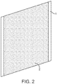
- Figure 2 is a prospective view of a coated iron electrode.
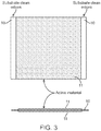
- the substrate 1 is coated on each side with a coating 2 comprising the iron active material and binder. This is further shown in Figure 3 .
- the substrate 10 is coated on each side with the coating 11 of the iron active material and binder.
- the substrate may be coated continuously across the surface of the substrate, or preferably, as shown in Figures 2 and 3 , cleared lanes of substrate may be uncoated to simplify subsequent operations such as welding of current collector tabs.
- FIGs 4 and 5 of the drawing show a conventional pocket iron electrode.
- the two substrates 30 are shown to form the pocket which holds the iron active material.
- the iron active material 40 is held between the two substrates 41 and 42.
- a water based paste comprised of hydrogen reduced iron powder (325 mesh size), 16% nickel powder #255, 0.5% elemental sulfur powder (precipitated, purified) and the appropriate amount of binder was prepared using a digital stirring device and 3-wing stirring blade operating at 1300 RPM for 10-15 minutes. Deionized water was added to the mixture to create a paste with a viscosity between 120,000-130,000 cP.
- the water based paste was applied to a 4.14 cm (1.63 inch) wide nickel-plated continuous perforated strip with 2-mm perforations by feeding the strip fed through the top of an open-bottomed pot attached to a doctor-blade fixture with a gap width set to 0.17 cm (0.068 inch).
- the paste mixture is poured into the pot and the perforated strip is pulled down at a rate of 82 cm/ min (2.7 ft/min) coating the perforated strip with the paste mixture. Segments ranging 10-13 cm (4-5 inch) are cut from the coated strip and placed into a drying oven at 65.6°C (150 °F) for 20 minutes.
- the coated strips were cut to a standard length of 7.6 cm (3 inch) and then compressed to thickness to achieve a porosity of approximately 40%. Dried paste mixture was removed from the top 0.64 cm (0.25 inch) of the strip in order to provide a clean space for a stainless steel tab to be spot-welded onto.
- a series of iron electrodes were prepared by impregnating nickel foam with various pastes comprising several different binder compositions described in Table 1.
- the discharge capacities of the individual cells prepared from these electrodes were measured and plotted against the amount of iron in the anode in Figure 6 .
- the effect of rate on capacity was evaluated by discharging the cells at multiple rates of C/10, C/5, C/2, and 2C where C represents the current required to discharge the cell in one hour.
- Table 1 Cell # Binder Binder g of iron 1 1% CMC 1% PTFE 6.4 2 1% PVA 1% PTFE 8.5 3 1% CMC 1% AL-2002 latex 7.9 4 1% CMC 1% AL-3001 latex 7.4 5 1% PVA 1% AL-1002 latex 8.3
- Cells # 1-5 are reference examples.
- the binder can contribute to electrode resistance, it is desirable to employ a binder that minimizes an increase in cell resistance and offers the highest mA h/g capacity. Comparing the 2C capacities of the Ni-Fe batteries, the best results at 2C discharge rate were obtained in cells employing PVA as a binder.
- Samples 5 and 6 are reference examples.
- the coated strips were cut to a standard length of 7.6 cm (3 inch) and then compressed to thickness to achieve a porosity of approximately 40%. Dried paste mixture was removed from the top 0.64 cm (0.25 inch) of the strip in order to provide a clean space for a stainless steel tab to be spot-welded onto.
- a series of continuously coated iron electrodes were prepared by coating perforated NPS with an aqueous mixture of iron powder, nickel powder as a conductivity aid, elemental sulfur and employing PVA as a binder. Multiple levels of PVA were employed in the mixes to evaluate the effect of binder concentration on mechanical stability of the electrode and rate capability of the electrode. At concentrations below 3 weight percent PVA, the physical integrity of the electrodes was unacceptable. Concentrations of binder above about 5 weight percent showed a sharp drop in discharge capacity, most likely due to increased electrode resistance and possibly masking of the active material from the electrolyte interface. Data for cells with varying levels of PVA is summarized in Table 2.
- the paste mixture was then transferred to a jacketed holding tank preheated to 43.3 °C (110 °F) where it was stirred.
- the paste was pumped to a paste hopper where a perforated nickel plated steel strip was coated.
- the coated strip was then passed through a doctor blade to achieve a coating thickness between 0.10-0.13 cm (0.040-0.050 inch) and introduced to a vertical drying oven.
- the first stage of drying consisted of IR heating at 116 °C (240 °F) for 1.67 minutes followed by heating in a conventional oven at 116 °C (240 °F) for 3.35 minutes.
- the second drying stage with a residence time of 1.7 minutes consisted of forced hot air with a set drying temperature of 127 °C (260 °F).
- the paste temperature exiting the ovens did not exceed 98.9 °C (210 °F).
- the finished coating was calendared to a thickness of 0.064 cm (0.025 inch). Pieces of the coating were cut to size and weighed to obtain coating porosity. The porosity ranged from 34 - 43% with a targeted porosity of 38%.
- Electrodes from Example 4 were used to construct a Ni-Fe battery.
- Table 3 shows the performance of the iron electrode in comparison to other commercial Ni-Fe batteries employing pocket plate electrodes.
- Table 3 Cell Chinese Seiden Chinese Taihang Ukrainian Russian Zappworks Electrode of present invention Ah/g (powder) 0.095 Ah/g 0.130Ah/g 0.117 Ah/g 0.116Ah/g - 0.126 Ah/g Ah/g (total electrode) 0.059 Ah/g 0.076 Ah/g 0.075 Ah/g 0.084 Ah/g 0.034 Ah/g 0.105 Ah/g Ah/cm 3 (total electrode) 0.199 Ah/cm 3 0.203 Ah/cm 3 0.216 Ah/cm 3 0.238 Ah/cm 3 0.099 Ah/cm 3 0.430 Ah/cm 3 Type of iron electrode Pocket plate Pocket plate Pocket plate Pocket plate Pocket plate Pocket plate Pocket plate Pocket plate Continuous coated (Pasted)
- a water based paste comprised of hydrogen reduced iron powder (325 mesh size), nickel powder #255, elemental sulfur powder (precipitated, purified) and the appropriate amount of binder was prepared using a digital stirring device and 3-wing stirring blade operating at 1300 RPM for 10-15 minutes. Deionized water was added to the mixture to create a paste with a viscosity between 120,000-130,000 cP.
- the nickel and iron content was varied according to Table 3, the sulfur content was 0.5%, and the binder content was 3.5%.
- the coated strips were cut to a standard length of 7.6 cm (3 inch) and then compressed to thickness to achieve a porosity of approximately 40%. Dried paste mixture was removed from the top 0.64 cm (0.25 inch) of the strip in order to provide a clean space for a stainless steel tab to be spot-welded onto.
- Ni-Fe cells were constructed using electrodes fabricated from the pastes with varying nickel and iron content. The data is shown in Figure 7 . The cell performance does not appear to be very dependent upon nickel concentration in the concentration range between 8-16% but improved capacity at high (1 C) and low rates (C/10) is observed for electrodes with 20% nickel.
- a water based paste comprised of hydrogen reduced iron powder (325 mesh size), nickel powder #255, elemental sulfur powder (precipitated, purified) and the appropriate amount of binder was prepared using a digital stirring device and 3-wing stirring blade operating at 1300 RPM for 10-15 minutes. Deionized water was added to the mixture to create a paste with a viscosity between 120,000-130,000 cP.
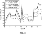
- the nickel content was 16%, polyvinyl alcohol 3.5%, and the sulfur content was varied between 0 and 1.5 % with the remainder of the electrode composition being iron powder.
- Water based pastes with varying sulfur content were applied to a 4.14 cm (1.63 inch) wide nickel-plated perforated strip with 2-mm perforations by feeding the strip fed through the top of an open-bottomed pot attached to a doctor-blade fixture with a gap width set to 0.17 cm (0.068 inch).
- the paste mixture is poured into the pot and the perforated strip is pulled down at a rate of 82 cm/min (2.7 ft/min) coating the perforated strip with the paste mixture. Segments ranging 10-13 cm (4-5 inch) are cut from the coated strip and placed into a drying oven at 150 °C for 20 minutes.
- the coated strips were cut to a standard length of 7.6 cm (3 inch) and then compressed to thickness to achieve a porosity of approximately 40%. Dried paste mixture was removed from the top 0.64 cm (0.25 inch) of the strip in order to provide a clean space for a stainless steel tab to be spot-welded onto.
- Ni-Fe cells were constructed using electrodes fabricated from the pastes with varying sulfur content. The data is shown in Figure 8 . Increasing the sulfur content of the electrode increases the capacity at the C/10 discharge rate until the sulfur content reaches about 1.5% where there is no further increase in capacity. Increasing the sulfur content increased the capacity of the iron electrode even at sulfur contents up to 1.5% at the 1 C and 2C discharge rates.
- Ni-Fe cells constructed with iron electrodes prepared using the process of the foregoing examples an electrolyte comprising sodium hydroxide (NaOH), lithium hydroxide (LiOH), and sodium sulfide (Na 2 S) was used.
- a sintered nickel electrode impregnated with nickel hydroxide was used as the positive electrode and a 0.010 inch thick polyolefin nonwoven mesh was used as the separator in these examples of Ni-Fe cells with the iron electrode of the present invention.
- the electrolyte used in the conventional Ni-Fe battery was potassium hydroxide (KOH) and the anode and cathode were kept electrically isolated using a spacer. The results show a vast improvement in performance characteristics for the inventive Ni-Fe battery.
Landscapes
- Chemical & Material Sciences (AREA)
- Chemical Kinetics & Catalysis (AREA)
- Electrochemistry (AREA)
- General Chemical & Material Sciences (AREA)
- Engineering & Computer Science (AREA)
- Manufacturing & Machinery (AREA)
- Composite Materials (AREA)
- Inorganic Chemistry (AREA)
- Battery Electrode And Active Subsutance (AREA)
- Cell Electrode Carriers And Collectors (AREA)
- Secondary Cells (AREA)
Claims (13)
- Une électrode qui comprend une seule couche d'un substrat conducteur revêtue sur au moins une face d'un revêtement comprenant un matériau actif ferreux et un liant, dans laquelle le liant comprend de l'alcool de polyvinyle et du soufre élémentaire, et dans laquelle la quantité d'alcool de polyvinyle dans l'électrode est dans la plage allant de 2,5 à 5 % en poids.
- L'électrode en fer selon la revendication 1, qui comprend une seule couche d'un substrat conducteur revêtue sur au moins une face d'un revêtement comprenant un matériau actif ferreux, avec le revêtement comprenant au moins deux couches.
- L'électrode en fer selon la revendication 2, dans laquelle le revêtement comprend deux couches, ou dans laquelle le revêtement comprend trois couches.
- L'électrode en fer selon la revendication 3, dans laquelle les deux couches ou au moins deux des trois couches ont des porosités différentes.
- L'électrode en fer selon la revendication 3, dans laquelle les deux couches ou au moins deux des trois couches ont une composition différente.
- L'électrode en fer selon la revendication 1, dans laquelle la quantité d'alcool de polyvinyle dans l'électrode est dans la plage allant de 2,5 à 4 % en poids.
- L'électrode en fer selon la revendication 1, dans laquelle l'électrode en fer comprend en outre un additif.
- Un procédé de préparation d'une électrode en fer, comprenant :- la préparation d'un mélange comprenant un matériau actif ferreux, du soufre élémentaire et un liant ;- le revêtement d'un matériau de substrat continu sur au moins une face avec le mélange ;- le séchage, le compactage et la découpe de l'électrode sur mesure ; et la fixation d'une languette à l'électrode,- dans laquelle le liant comprend de l'alcool de polyvinyle et dans laquelle la quantité d'alcool de polyvinyle dans l'électrode est dans la plage allant de 2,5 à 5 % en poids.
- Le procédé selon la revendication 8, dans lequel la quantité d'alcool de polyvinyle dans l'électrode est dans la plage allant de 2,5 à 4 % en poids.
- Le procédé selon la revendication 8, dans lequel le revêtement du substrat continu comprend la superposition de matériaux ayant des propriétés différentes.
- Le procédé selon la revendication 10, dans lequel les couches ont des porosités et / ou des densités différentes et / ou des concentrations différentes d'additifs.
- Le procédé selon la revendication 8, dans lequel le séchage est effectué avec une combinaison de séchage IR, micro-ondes ou UV dans une première étape, et de séchage par convection dans une deuxième étape.
- Une batterie comprenant une cathode à base de nickel et l'électrode de l'une quelconque des revendications 1 à 7 comme anode.
Applications Claiming Priority (5)
| Application Number | Priority Date | Filing Date | Title |
|---|---|---|---|
| US201361759777P | 2013-02-01 | 2013-02-01 | |
| US201361898191P | 2013-10-31 | 2013-10-31 | |
| US201361898151P | 2013-10-31 | 2013-10-31 | |
| US201361902041P | 2013-11-08 | 2013-11-08 | |
| PCT/US2014/014028 WO2014121009A1 (fr) | 2013-02-01 | 2014-01-31 | Électrode en fer revêtue et son procédé de fabrication |
Publications (3)
| Publication Number | Publication Date |
|---|---|
| EP2951335A1 EP2951335A1 (fr) | 2015-12-09 |
| EP2951335A4 EP2951335A4 (fr) | 2016-08-17 |
| EP2951335B1 true EP2951335B1 (fr) | 2019-08-21 |
Family
ID=51262963
Family Applications (1)
| Application Number | Title | Priority Date | Filing Date |
|---|---|---|---|
| EP14745486.2A Active EP2951335B1 (fr) | 2013-02-01 | 2014-01-31 | Électrode en fer revêtue et son procédé de fabrication |
Country Status (9)
| Country | Link |
|---|---|
| EP (1) | EP2951335B1 (fr) |
| JP (1) | JP6385368B2 (fr) |
| CN (1) | CN105143519B (fr) |
| AU (1) | AU2014212256B2 (fr) |
| CA (1) | CA2899333C (fr) |
| ES (1) | ES2756523T3 (fr) |
| IL (1) | IL240234B (fr) |
| MX (1) | MX2015009648A (fr) |
| WO (1) | WO2014121009A1 (fr) |
Families Citing this family (4)
| Publication number | Priority date | Publication date | Assignee | Title |
|---|---|---|---|---|
| JP6579041B2 (ja) * | 2016-05-31 | 2019-09-25 | トヨタ自動車株式会社 | 電池負極用活物質、電池、電池負極用活物質の製造方法 |
| CN106986427B (zh) * | 2017-04-28 | 2020-09-15 | 南京大学连云港高新技术研究院 | 一种简化节能型催化极板的制备方法 |
| CN109686978B (zh) * | 2018-12-03 | 2022-11-22 | 河南师范大学 | 一种碱性二次电池铁电极添加剂,制备方法和使用该添加剂的铁基负极板和应用 |
| CN109755499B (zh) * | 2018-12-03 | 2022-11-22 | 河南师范大学 | 一种铁镍二次电池负极添加剂,制备方法及使用该添加剂的铁基负极板和应用 |
Citations (2)
| Publication number | Priority date | Publication date | Assignee | Title |
|---|---|---|---|---|
| WO2010069209A1 (fr) * | 2008-12-17 | 2010-06-24 | 成都和能科技有限公司 | Matériau d'électrode à base de fer avec autodécharge limitée |
| EP2461399A1 (fr) * | 2009-07-31 | 2012-06-06 | Toda Kogyo Corporation | Matériau actif pour électrode positive de batterie secondaire à électrolyte non aqueux, et batterie secondaire à électrolyte non aqueux |
Family Cites Families (17)
| Publication number | Priority date | Publication date | Assignee | Title |
|---|---|---|---|---|
| US3630781A (en) * | 1968-07-03 | 1971-12-28 | Gen Electric | Process of forming rechargeable electrodes utilizing unsintered fluorocarbon binder |
| GB1359746A (en) * | 1971-02-18 | 1974-07-10 | Wenstingouse Electric Corp | Negative iron battery electrodes |
| US3819413A (en) * | 1971-12-23 | 1974-06-25 | Siemens Ag | Rechargeable metal electrode for storage batteries and metal-air cells |
| US4021911A (en) * | 1976-01-07 | 1977-05-10 | Viktor Evmenievich Kononenko | Method for producing an iron electrode for an alkaline accumulator |
| US4123568A (en) * | 1976-06-01 | 1978-10-31 | Viktor Evmenievich Kononenko | Method of manufacturing an iron electrode for alkaline accumulators |
| JPS53142630A (en) * | 1977-05-18 | 1978-12-12 | Sanyo Electric Co | Method of manufacturing cadmium electrode for alkaline battery |
| JPH06295727A (ja) * | 1993-04-09 | 1994-10-21 | Toshiba Battery Co Ltd | 密閉式アルカリ蓄電池 |
| US5780184A (en) * | 1995-04-24 | 1998-07-14 | Saft | Negative electrode for an alkaline cell |
| JP2001176502A (ja) * | 1999-10-06 | 2001-06-29 | Matsushita Electric Ind Co Ltd | 電池用電極の製造方法 |
| JP2006024414A (ja) * | 2004-07-07 | 2006-01-26 | Sony Corp | 電池 |
| US8936873B2 (en) * | 2005-08-16 | 2015-01-20 | Lg Chem, Ltd. | Cathode active material and lithium secondary battery containing them |
| JP5217095B2 (ja) * | 2006-02-10 | 2013-06-19 | トヨタ自動車株式会社 | 非水系二次電池の製造方法、及び、電極の製造方法 |
| US20080057403A1 (en) * | 2006-09-06 | 2008-03-06 | Issaev Nikolai N | Lithium cell |
| US20120070746A1 (en) * | 2007-09-21 | 2012-03-22 | Sion Power Corporation | Low electrolyte electrochemical cells |
| JP5810479B2 (ja) * | 2009-05-26 | 2015-11-11 | 日産自動車株式会社 | リチウムイオン二次電池用の電極構造、リチウムイオン二次電池およびリチウムイオン二次電池用の電極の製造方法 |
| TWI385842B (zh) * | 2009-07-21 | 2013-02-11 | Nat Univ Tsing Hua | 電池電極製作方法 |
| JP5621738B2 (ja) * | 2011-09-16 | 2014-11-12 | トヨタ自動車株式会社 | 電極活物質及びこれを用いたニッケル鉄電池並びに電極活物質の製造方法 |
-
2014
- 2014-01-31 ES ES14745486T patent/ES2756523T3/es active Active
- 2014-01-31 CN CN201480005588.8A patent/CN105143519B/zh active Active
- 2014-01-31 WO PCT/US2014/014028 patent/WO2014121009A1/fr active Application Filing
- 2014-01-31 CA CA2899333A patent/CA2899333C/fr active Active
- 2014-01-31 MX MX2015009648A patent/MX2015009648A/es active IP Right Grant
- 2014-01-31 AU AU2014212256A patent/AU2014212256B2/en active Active
- 2014-01-31 JP JP2015556150A patent/JP6385368B2/ja active Active
- 2014-01-31 EP EP14745486.2A patent/EP2951335B1/fr active Active
-
2015
- 2015-07-29 IL IL240234A patent/IL240234B/en active IP Right Grant
Patent Citations (2)
| Publication number | Priority date | Publication date | Assignee | Title |
|---|---|---|---|---|
| WO2010069209A1 (fr) * | 2008-12-17 | 2010-06-24 | 成都和能科技有限公司 | Matériau d'électrode à base de fer avec autodécharge limitée |
| EP2461399A1 (fr) * | 2009-07-31 | 2012-06-06 | Toda Kogyo Corporation | Matériau actif pour électrode positive de batterie secondaire à électrolyte non aqueux, et batterie secondaire à électrolyte non aqueux |
Also Published As
| Publication number | Publication date |
|---|---|
| CN105143519B (zh) | 2018-05-04 |
| IL240234B (en) | 2019-09-26 |
| AU2014212256B2 (en) | 2017-12-21 |
| WO2014121009A1 (fr) | 2014-08-07 |
| CN105143519A (zh) | 2015-12-09 |
| EP2951335A4 (fr) | 2016-08-17 |
| ES2756523T3 (es) | 2020-04-27 |
| EP2951335A1 (fr) | 2015-12-09 |
| JP6385368B2 (ja) | 2018-09-05 |
| AU2014212256A1 (en) | 2015-08-27 |
| MX2015009648A (es) | 2016-04-25 |
| IL240234A0 (en) | 2015-09-24 |
| JP2016509351A (ja) | 2016-03-24 |
| CA2899333A1 (fr) | 2014-08-07 |
| CA2899333C (fr) | 2021-10-26 |
Similar Documents
| Publication | Publication Date | Title |
|---|---|---|
| US20230101375A1 (en) | Iron electrode employing a polyvinyl alcohol binder | |
| US20230121023A1 (en) | Continuous manufacture ofa nickel-iron battery | |
| US20230129997A1 (en) | Continuous coated iron electrode | |
| US20140220434A1 (en) | Nickel iron battery employing a coated iron electrode | |
| US10804523B2 (en) | Coated iron electrode and method of making same | |
| US9368788B2 (en) | Layered iron electrode | |
| US20140322598A1 (en) | Nickel-iron battery with high power | |
| EP2951335B1 (fr) | Électrode en fer revêtue et son procédé de fabrication | |
| US20170237063A1 (en) | Battery comprising a coated iron anode | |
| JP2001143687A (ja) | 非水系二次電池用正極 | |
| JP3972417B2 (ja) | 密閉形金属酸化物−亜鉛蓄電池およびその製造法 | |
| US20150056505A1 (en) | Manganese and iron electrode cell | |
| US20230126166A1 (en) | Nickel iron battery employing a coated iron electrode | |
| EP2951871B1 (fr) | Électrode de fer employant un liant poly(alcool de vinyle) | |
| CN113474920A (zh) | 用于可再充电储能设备的电极 | |
| WO2023195233A1 (fr) | Électrode négative pour batterie au zinc, et batterie au zinc | |
| US20150056504A1 (en) | Manganese and iron electrode cell | |
| JP2002157998A (ja) | 固体型リチウム二次電池用複合正極の製造方法及び該正極を用いた固体型リチウム二次電池 | |
| JP2018186093A (ja) | コーティングされた鉄アノード及び改善された性能を備えるバッテリー |
Legal Events
| Date | Code | Title | Description |
|---|---|---|---|
| PUAI | Public reference made under article 153(3) epc to a published international application that has entered the european phase |
Free format text: ORIGINAL CODE: 0009012 |
|
| 17P | Request for examination filed |
Effective date: 20150806 |
|
| AK | Designated contracting states |
Kind code of ref document: A1 Designated state(s): AL AT BE BG CH CY CZ DE DK EE ES FI FR GB GR HR HU IE IS IT LI LT LU LV MC MK MT NL NO PL PT RO RS SE SI SK SM TR |
|
| AX | Request for extension of the european patent |
Extension state: BA ME |
|
| DAX | Request for extension of the european patent (deleted) | ||
| REG | Reference to a national code |
Ref country code: DE Ref legal event code: R079 Ref document number: 602014052158 Country of ref document: DE Free format text: PREVIOUS MAIN CLASS: C25B0011000000 Ipc: H01M0004040000 |
|
| A4 | Supplementary search report drawn up and despatched |
Effective date: 20160720 |
|
| RIC1 | Information provided on ipc code assigned before grant |
Ipc: H01M 4/36 20060101ALI20160714BHEP Ipc: H01M 4/62 20060101ALI20160714BHEP Ipc: H01M 4/38 20060101ALI20160714BHEP Ipc: H01M 4/52 20060101ALI20160714BHEP Ipc: H01M 10/30 20060101ALI20160714BHEP Ipc: H01M 4/24 20060101ALI20160714BHEP Ipc: H01M 4/04 20060101AFI20160714BHEP |
|
| STAA | Information on the status of an ep patent application or granted ep patent |
Free format text: STATUS: EXAMINATION IS IN PROGRESS |
|
| 17Q | First examination report despatched |
Effective date: 20180208 |
|
| GRAP | Despatch of communication of intention to grant a patent |
Free format text: ORIGINAL CODE: EPIDOSNIGR1 |
|
| STAA | Information on the status of an ep patent application or granted ep patent |
Free format text: STATUS: GRANT OF PATENT IS INTENDED |
|
| INTG | Intention to grant announced |
Effective date: 20190425 |
|
| GRAS | Grant fee paid |
Free format text: ORIGINAL CODE: EPIDOSNIGR3 |
|
| GRAA | (expected) grant |
Free format text: ORIGINAL CODE: 0009210 |
|
| STAA | Information on the status of an ep patent application or granted ep patent |
Free format text: STATUS: THE PATENT HAS BEEN GRANTED |
|
| AK | Designated contracting states |
Kind code of ref document: B1 Designated state(s): AL AT BE BG CH CY CZ DE DK EE ES FI FR GB GR HR HU IE IS IT LI LT LU LV MC MK MT NL NO PL PT RO RS SE SI SK SM TR |
|
| REG | Reference to a national code |
Ref country code: GB Ref legal event code: FG4D |
|
| REG | Reference to a national code |
Ref country code: CH Ref legal event code: EP |
|
| REG | Reference to a national code |
Ref country code: DE Ref legal event code: R096 Ref document number: 602014052158 Country of ref document: DE |
|
| REG | Reference to a national code |
Ref country code: AT Ref legal event code: REF Ref document number: 1170766 Country of ref document: AT Kind code of ref document: T Effective date: 20190915 |
|
| REG | Reference to a national code |
Ref country code: IE Ref legal event code: FG4D |
|
| REG | Reference to a national code |
Ref country code: NL Ref legal event code: FP |
|
| REG | Reference to a national code |
Ref country code: LT Ref legal event code: MG4D |
|
| REG | Reference to a national code |
Ref country code: NO Ref legal event code: T2 Effective date: 20190821 |
|
| PG25 | Lapsed in a contracting state [announced via postgrant information from national office to epo] |
Ref country code: BG Free format text: LAPSE BECAUSE OF FAILURE TO SUBMIT A TRANSLATION OF THE DESCRIPTION OR TO PAY THE FEE WITHIN THE PRESCRIBED TIME-LIMIT Effective date: 20191121 Ref country code: SE Free format text: LAPSE BECAUSE OF FAILURE TO SUBMIT A TRANSLATION OF THE DESCRIPTION OR TO PAY THE FEE WITHIN THE PRESCRIBED TIME-LIMIT Effective date: 20190821 Ref country code: LT Free format text: LAPSE BECAUSE OF FAILURE TO SUBMIT A TRANSLATION OF THE DESCRIPTION OR TO PAY THE FEE WITHIN THE PRESCRIBED TIME-LIMIT Effective date: 20190821 Ref country code: PT Free format text: LAPSE BECAUSE OF FAILURE TO SUBMIT A TRANSLATION OF THE DESCRIPTION OR TO PAY THE FEE WITHIN THE PRESCRIBED TIME-LIMIT Effective date: 20191223 Ref country code: HR Free format text: LAPSE BECAUSE OF FAILURE TO SUBMIT A TRANSLATION OF THE DESCRIPTION OR TO PAY THE FEE WITHIN THE PRESCRIBED TIME-LIMIT Effective date: 20190821 Ref country code: FI Free format text: LAPSE BECAUSE OF FAILURE TO SUBMIT A TRANSLATION OF THE DESCRIPTION OR TO PAY THE FEE WITHIN THE PRESCRIBED TIME-LIMIT Effective date: 20190821 |
|
| PG25 | Lapsed in a contracting state [announced via postgrant information from national office to epo] |
Ref country code: AL Free format text: LAPSE BECAUSE OF FAILURE TO SUBMIT A TRANSLATION OF THE DESCRIPTION OR TO PAY THE FEE WITHIN THE PRESCRIBED TIME-LIMIT Effective date: 20190821 Ref country code: LV Free format text: LAPSE BECAUSE OF FAILURE TO SUBMIT A TRANSLATION OF THE DESCRIPTION OR TO PAY THE FEE WITHIN THE PRESCRIBED TIME-LIMIT Effective date: 20190821 Ref country code: IS Free format text: LAPSE BECAUSE OF FAILURE TO SUBMIT A TRANSLATION OF THE DESCRIPTION OR TO PAY THE FEE WITHIN THE PRESCRIBED TIME-LIMIT Effective date: 20191221 Ref country code: RS Free format text: LAPSE BECAUSE OF FAILURE TO SUBMIT A TRANSLATION OF THE DESCRIPTION OR TO PAY THE FEE WITHIN THE PRESCRIBED TIME-LIMIT Effective date: 20190821 Ref country code: GR Free format text: LAPSE BECAUSE OF FAILURE TO SUBMIT A TRANSLATION OF THE DESCRIPTION OR TO PAY THE FEE WITHIN THE PRESCRIBED TIME-LIMIT Effective date: 20191122 |
|
| REG | Reference to a national code |
Ref country code: AT Ref legal event code: MK05 Ref document number: 1170766 Country of ref document: AT Kind code of ref document: T Effective date: 20190821 |
|
| REG | Reference to a national code |
Ref country code: ES Ref legal event code: FG2A Ref document number: 2756523 Country of ref document: ES Kind code of ref document: T3 Effective date: 20200427 |
|
| PG25 | Lapsed in a contracting state [announced via postgrant information from national office to epo] |
Ref country code: AT Free format text: LAPSE BECAUSE OF FAILURE TO SUBMIT A TRANSLATION OF THE DESCRIPTION OR TO PAY THE FEE WITHIN THE PRESCRIBED TIME-LIMIT Effective date: 20190821 Ref country code: RO Free format text: LAPSE BECAUSE OF FAILURE TO SUBMIT A TRANSLATION OF THE DESCRIPTION OR TO PAY THE FEE WITHIN THE PRESCRIBED TIME-LIMIT Effective date: 20190821 Ref country code: EE Free format text: LAPSE BECAUSE OF FAILURE TO SUBMIT A TRANSLATION OF THE DESCRIPTION OR TO PAY THE FEE WITHIN THE PRESCRIBED TIME-LIMIT Effective date: 20190821 Ref country code: IT Free format text: LAPSE BECAUSE OF FAILURE TO SUBMIT A TRANSLATION OF THE DESCRIPTION OR TO PAY THE FEE WITHIN THE PRESCRIBED TIME-LIMIT Effective date: 20190821 Ref country code: PL Free format text: LAPSE BECAUSE OF FAILURE TO SUBMIT A TRANSLATION OF THE DESCRIPTION OR TO PAY THE FEE WITHIN THE PRESCRIBED TIME-LIMIT Effective date: 20190821 Ref country code: DK Free format text: LAPSE BECAUSE OF FAILURE TO SUBMIT A TRANSLATION OF THE DESCRIPTION OR TO PAY THE FEE WITHIN THE PRESCRIBED TIME-LIMIT Effective date: 20190821 |
|
| PG25 | Lapsed in a contracting state [announced via postgrant information from national office to epo] |
Ref country code: IS Free format text: LAPSE BECAUSE OF FAILURE TO SUBMIT A TRANSLATION OF THE DESCRIPTION OR TO PAY THE FEE WITHIN THE PRESCRIBED TIME-LIMIT Effective date: 20200224 Ref country code: SM Free format text: LAPSE BECAUSE OF FAILURE TO SUBMIT A TRANSLATION OF THE DESCRIPTION OR TO PAY THE FEE WITHIN THE PRESCRIBED TIME-LIMIT Effective date: 20190821 Ref country code: SK Free format text: LAPSE BECAUSE OF FAILURE TO SUBMIT A TRANSLATION OF THE DESCRIPTION OR TO PAY THE FEE WITHIN THE PRESCRIBED TIME-LIMIT Effective date: 20190821 Ref country code: CZ Free format text: LAPSE BECAUSE OF FAILURE TO SUBMIT A TRANSLATION OF THE DESCRIPTION OR TO PAY THE FEE WITHIN THE PRESCRIBED TIME-LIMIT Effective date: 20190821 |
|
| REG | Reference to a national code |
Ref country code: DE Ref legal event code: R097 Ref document number: 602014052158 Country of ref document: DE |
|
| PLBE | No opposition filed within time limit |
Free format text: ORIGINAL CODE: 0009261 |
|
| STAA | Information on the status of an ep patent application or granted ep patent |
Free format text: STATUS: NO OPPOSITION FILED WITHIN TIME LIMIT |
|
| PG2D | Information on lapse in contracting state deleted |
Ref country code: IS |
|
| 26N | No opposition filed |
Effective date: 20200603 |
|
| PG25 | Lapsed in a contracting state [announced via postgrant information from national office to epo] |
Ref country code: MC Free format text: LAPSE BECAUSE OF FAILURE TO SUBMIT A TRANSLATION OF THE DESCRIPTION OR TO PAY THE FEE WITHIN THE PRESCRIBED TIME-LIMIT Effective date: 20190821 Ref country code: SI Free format text: LAPSE BECAUSE OF FAILURE TO SUBMIT A TRANSLATION OF THE DESCRIPTION OR TO PAY THE FEE WITHIN THE PRESCRIBED TIME-LIMIT Effective date: 20190821 |
|
| REG | Reference to a national code |
Ref country code: CH Ref legal event code: PL |
|
| PG25 | Lapsed in a contracting state [announced via postgrant information from national office to epo] |
Ref country code: LU Free format text: LAPSE BECAUSE OF NON-PAYMENT OF DUE FEES Effective date: 20200131 |
|
| PG25 | Lapsed in a contracting state [announced via postgrant information from national office to epo] |
Ref country code: CH Free format text: LAPSE BECAUSE OF NON-PAYMENT OF DUE FEES Effective date: 20200131 Ref country code: LI Free format text: LAPSE BECAUSE OF NON-PAYMENT OF DUE FEES Effective date: 20200131 |
|
| REG | Reference to a national code |
Ref country code: DE Ref legal event code: R082 Ref document number: 602014052158 Country of ref document: DE Representative=s name: HL KEMPNER PATENTANWAELTE, SOLICITORS (ENGLAND, DE Ref country code: DE Ref legal event code: R082 Ref document number: 602014052158 Country of ref document: DE Representative=s name: HL KEMPNER PATENTANWALT, RECHTSANWALT, SOLICIT, DE |
|
| PG25 | Lapsed in a contracting state [announced via postgrant information from national office to epo] |
Ref country code: FR Free format text: LAPSE BECAUSE OF NON-PAYMENT OF DUE FEES Effective date: 20210131 |
|
| PG25 | Lapsed in a contracting state [announced via postgrant information from national office to epo] |
Ref country code: FR Free format text: LAPSE BECAUSE OF NON-PAYMENT OF DUE FEES Effective date: 20210131 |
|
| PGRI | Patent reinstated in contracting state [announced from national office to epo] |
Ref country code: FR Effective date: 20211228 |
|
| PG25 | Lapsed in a contracting state [announced via postgrant information from national office to epo] |
Ref country code: MT Free format text: LAPSE BECAUSE OF FAILURE TO SUBMIT A TRANSLATION OF THE DESCRIPTION OR TO PAY THE FEE WITHIN THE PRESCRIBED TIME-LIMIT Effective date: 20190821 Ref country code: CY Free format text: LAPSE BECAUSE OF FAILURE TO SUBMIT A TRANSLATION OF THE DESCRIPTION OR TO PAY THE FEE WITHIN THE PRESCRIBED TIME-LIMIT Effective date: 20190821 |
|
| PG25 | Lapsed in a contracting state [announced via postgrant information from national office to epo] |
Ref country code: MK Free format text: LAPSE BECAUSE OF FAILURE TO SUBMIT A TRANSLATION OF THE DESCRIPTION OR TO PAY THE FEE WITHIN THE PRESCRIBED TIME-LIMIT Effective date: 20190821 |
|
| PGFP | Annual fee paid to national office [announced via postgrant information from national office to epo] |
Ref country code: NO Payment date: 20230110 Year of fee payment: 10 |
|
| PGFP | Annual fee paid to national office [announced via postgrant information from national office to epo] |
Ref country code: TR Payment date: 20230130 Year of fee payment: 10 |
|
| PGFP | Annual fee paid to national office [announced via postgrant information from national office to epo] |
Ref country code: GB Payment date: 20231207 Year of fee payment: 11 |
|
| PGFP | Annual fee paid to national office [announced via postgrant information from national office to epo] |
Ref country code: NL Payment date: 20231215 Year of fee payment: 11 Ref country code: IE Payment date: 20231211 Year of fee payment: 11 Ref country code: FR Payment date: 20231212 Year of fee payment: 11 |
|
| PGFP | Annual fee paid to national office [announced via postgrant information from national office to epo] |
Ref country code: BE Payment date: 20231219 Year of fee payment: 11 |
|
| PGFP | Annual fee paid to national office [announced via postgrant information from national office to epo] |
Ref country code: ES Payment date: 20240207 Year of fee payment: 11 |
|
| PGFP | Annual fee paid to national office [announced via postgrant information from national office to epo] |
Ref country code: DE Payment date: 20231205 Year of fee payment: 11 |