EP2951066B1 - Kühlkreislauf für ein kraftfahrzeug mit einem hydrodynamischen retarder - Google Patents
Kühlkreislauf für ein kraftfahrzeug mit einem hydrodynamischen retarder Download PDFInfo
- Publication number
- EP2951066B1 EP2951066B1 EP14701551.5A EP14701551A EP2951066B1 EP 2951066 B1 EP2951066 B1 EP 2951066B1 EP 14701551 A EP14701551 A EP 14701551A EP 2951066 B1 EP2951066 B1 EP 2951066B1
- Authority
- EP
- European Patent Office
- Prior art keywords
- flow
- cooling medium
- cooling
- return
- main circuit
- Prior art date
- Legal status (The legal status is an assumption and is not a legal conclusion. Google has not performed a legal analysis and makes no representation as to the accuracy of the status listed.)
- Active
Links
Images




Classifications
-
- B—PERFORMING OPERATIONS; TRANSPORTING
- B60—VEHICLES IN GENERAL
- B60T—VEHICLE BRAKE CONTROL SYSTEMS OR PARTS THEREOF; BRAKE CONTROL SYSTEMS OR PARTS THEREOF, IN GENERAL; ARRANGEMENT OF BRAKING ELEMENTS ON VEHICLES IN GENERAL; PORTABLE DEVICES FOR PREVENTING UNWANTED MOVEMENT OF VEHICLES; VEHICLE MODIFICATIONS TO FACILITATE COOLING OF BRAKES
- B60T1/00—Arrangements of braking elements, i.e. of those parts where braking effect occurs specially for vehicles
- B60T1/02—Arrangements of braking elements, i.e. of those parts where braking effect occurs specially for vehicles acting by retarding wheels
- B60T1/08—Arrangements of braking elements, i.e. of those parts where braking effect occurs specially for vehicles acting by retarding wheels using fluid or powdered medium
- B60T1/087—Arrangements of braking elements, i.e. of those parts where braking effect occurs specially for vehicles acting by retarding wheels using fluid or powdered medium in hydrodynamic, i.e. non-positive displacement, retarders
-
- B—PERFORMING OPERATIONS; TRANSPORTING
- B60—VEHICLES IN GENERAL
- B60T—VEHICLE BRAKE CONTROL SYSTEMS OR PARTS THEREOF; BRAKE CONTROL SYSTEMS OR PARTS THEREOF, IN GENERAL; ARRANGEMENT OF BRAKING ELEMENTS ON VEHICLES IN GENERAL; PORTABLE DEVICES FOR PREVENTING UNWANTED MOVEMENT OF VEHICLES; VEHICLE MODIFICATIONS TO FACILITATE COOLING OF BRAKES
- B60T5/00—Vehicle modifications to facilitate cooling of brakes
-
- B—PERFORMING OPERATIONS; TRANSPORTING
- B60—VEHICLES IN GENERAL
- B60T—VEHICLE BRAKE CONTROL SYSTEMS OR PARTS THEREOF; BRAKE CONTROL SYSTEMS OR PARTS THEREOF, IN GENERAL; ARRANGEMENT OF BRAKING ELEMENTS ON VEHICLES IN GENERAL; PORTABLE DEVICES FOR PREVENTING UNWANTED MOVEMENT OF VEHICLES; VEHICLE MODIFICATIONS TO FACILITATE COOLING OF BRAKES
- B60T10/00—Control or regulation for continuous braking making use of fluid or powdered medium, e.g. for use when descending a long slope
- B60T10/02—Control or regulation for continuous braking making use of fluid or powdered medium, e.g. for use when descending a long slope with hydrodynamic brake
-
- F—MECHANICAL ENGINEERING; LIGHTING; HEATING; WEAPONS; BLASTING
- F01—MACHINES OR ENGINES IN GENERAL; ENGINE PLANTS IN GENERAL; STEAM ENGINES
- F01P—COOLING OF MACHINES OR ENGINES IN GENERAL; COOLING OF INTERNAL-COMBUSTION ENGINES
- F01P3/00—Liquid cooling
- F01P3/20—Cooling circuits not specific to a single part of engine or machine
-
- F—MECHANICAL ENGINEERING; LIGHTING; HEATING; WEAPONS; BLASTING
- F01—MACHINES OR ENGINES IN GENERAL; ENGINE PLANTS IN GENERAL; STEAM ENGINES
- F01P—COOLING OF MACHINES OR ENGINES IN GENERAL; COOLING OF INTERNAL-COMBUSTION ENGINES
- F01P5/00—Pumping cooling-air or liquid coolants
- F01P5/10—Pumping liquid coolant; Arrangements of coolant pumps
- F01P5/12—Pump-driving arrangements
-
- F—MECHANICAL ENGINEERING; LIGHTING; HEATING; WEAPONS; BLASTING
- F01—MACHINES OR ENGINES IN GENERAL; ENGINE PLANTS IN GENERAL; STEAM ENGINES
- F01P—COOLING OF MACHINES OR ENGINES IN GENERAL; COOLING OF INTERNAL-COMBUSTION ENGINES
- F01P7/00—Controlling of coolant flow
- F01P7/14—Controlling of coolant flow the coolant being liquid
-
- F—MECHANICAL ENGINEERING; LIGHTING; HEATING; WEAPONS; BLASTING
- F16—ENGINEERING ELEMENTS AND UNITS; GENERAL MEASURES FOR PRODUCING AND MAINTAINING EFFECTIVE FUNCTIONING OF MACHINES OR INSTALLATIONS; THERMAL INSULATION IN GENERAL
- F16D—COUPLINGS FOR TRANSMITTING ROTATION; CLUTCHES; BRAKES
- F16D57/00—Liquid-resistance brakes; Brakes using the internal friction of fluids or fluid-like media, e.g. powders
- F16D57/04—Liquid-resistance brakes; Brakes using the internal friction of fluids or fluid-like media, e.g. powders with blades causing a directed flow, e.g. Föttinger type
-
- F—MECHANICAL ENGINEERING; LIGHTING; HEATING; WEAPONS; BLASTING
- F01—MACHINES OR ENGINES IN GENERAL; ENGINE PLANTS IN GENERAL; STEAM ENGINES
- F01P—COOLING OF MACHINES OR ENGINES IN GENERAL; COOLING OF INTERNAL-COMBUSTION ENGINES
- F01P2060/00—Cooling circuits using auxiliaries
- F01P2060/06—Retarder
-
- F—MECHANICAL ENGINEERING; LIGHTING; HEATING; WEAPONS; BLASTING
- F16—ENGINEERING ELEMENTS AND UNITS; GENERAL MEASURES FOR PRODUCING AND MAINTAINING EFFECTIVE FUNCTIONING OF MACHINES OR INSTALLATIONS; THERMAL INSULATION IN GENERAL
- F16D—COUPLINGS FOR TRANSMITTING ROTATION; CLUTCHES; BRAKES
- F16D65/00—Parts or details
- F16D65/78—Features relating to cooling
- F16D2065/782—Features relating to cooling the brake-actuating fluid being used as a coolant
Definitions
- the present invention relates to a cooling circuit for a motor vehicle, in which a hydrodynamic retarder is arranged, in detail according to the preamble of claim 1.
- so-called oil retarders which are operated with the working medium oil, which is circulated in a separate working medium circuit of the retarder
- so-called water retarder are known, which are directly integrated into the cooling circuit of a motor vehicle, which is usually operated with water or a water mixture as the cooling medium , Accordingly, the working medium of the retarder is at the same time the cooling medium of the cooling circuit.
- WO 97/33077 describes an embodiment with a hydrodynamic retarder in the cooling circuit of a motor vehicle, in which by a short circuit, which branches off downstream of the hydrodynamic retarder and opens upstream of the cooling medium pump, a particularly small minimum Retarderbremsmoment can be adjusted.
- the present invention is therefore based on the object to provide a cooling circuit for a motor vehicle, which allows a particularly low-loss integration of the hydrodynamic retarder in the cooling circuit.
- the cooling circuit according to the invention for a motor vehicle has a cooling medium pump, which circulates a cooling medium in the cooling circuit. Furthermore, a hydrodynamic retarder is provided, comprising a bladed primary wheel and a bladed secondary wheel, which together form a working space which can be filled with a working fluid. By driving the primary wheel, a hydrodynamic circulation flow of the working medium can be generated in the working space by means of which drive power is hydrodynamically transmitted from the primary wheel to the secondary wheel, whereby the primary wheel is braked.
- the secondary wheel can be provided as a non-rotating stator or as rotating in the opposite direction to the primary rotor.
- the cooling medium of the cooling circuit is at the same time the working medium of the hydrodynamic retarder.
- the cooling circuit has a main circuit in which the cooling medium pump is positioned. Furthermore, a drive motor and / or another unit of the motor vehicle is provided in the main circuit, which is cooled by means of the cooling medium. Finally, a heat exchanger for removing the recorded heat from the drive motor or the other unit heat of the cooling medium in the main circuit is positioned so that by driving the cooling medium pump, which is advantageous for this in a drive connection with the drive motor or can be driven by another motor, the cooling medium in Main circuit can be circulated to first receive the heat in the drive motor and / or the other unit and then in the heat exchanger, for example, to give the environment or to a secondary circuit.
- the hydrodynamic retarder is positioned in a secondary branch of the cooling circuit.
- the secondary branch comprises a feed, which branches off from the main circuit at a branching point and opens into the hydrodynamic retarder, and a return, which emanates from the hydrodynamic retarder and opens at a junction in the main circuit.
- cooling medium can be diverted from the main circuit as the working fluid of the hydrodynamic retarder, passed through the flow into the working space of the hydrodynamic retarder and are usually fed back to the main circuit after passing through the hydrodynamic circulation flow from the working space of the hydrodynamic retarder via the return.
- the return flows in the direction of flow of the cooling medium in the main circuit upstream of the branch point of the flow or at the branch point of the flow in the main circuit.
- the mouth of the return and the branch point of the flow are positioned on a common side of the cooling medium pump in the main circuit, that is, either together downstream of the cooling medium pump, that is on the pressure side, or together upstream of the cooling medium pump, that is on the suction side.
- the branch point of the flow in the main circuit is free of a flow in the flow diverting valve, in particular free of any valve.
- the junction of the return in the main circuit may be free of a flow in the return adjusting valve, in particular free of any valve.
- the main circuit is formed by a main channel, the flow through a flow channel and the return through a return channel, wherein the different channels can be integrated, for example in a common component, in particular cast component , and a first axial portion of the main channel, which is positioned in the direction of flow of the cooling medium in the main circuit immediately upstream of the branch point, parallel to the axial direction of an axial portion of the flow channel, which adjoins directly to the branch point extends, in particular aligned with this.
- a development of this embodiment provides that a second axial section of the main channel, which is positioned in the direction of flow of the cooling medium in the main circuit immediately downstream of the branch point surrounds the axial portion of the flow channel in the circumferential direction or is enclosed by this in the circumferential direction.
- An embodiment provides that a second axial section of the main channel, which is positioned in the direction of flow of the cooling medium in the main circuit immediately downstream of the branch point, runs parallel to the axial direction of an axial section of the return channel, which adjoins directly to the junction point, in particular with this flees.
- a further advantageous embodiment of the invention provides that, as previously shown, at least in the region of the junction and the branch point of the main circuit through a main channel, the flow through a flow channel and the return are formed by a return channel and now deviating a first axial section of the main channel , which is positioned in the direction of flow of the cooling medium in the main circuit immediately upstream of the branch point, parallel to the axial direction of a second axial section of the main channel, which is positioned in the direction of flow of the cooling medium in the main circuit immediately downstream of the branch point runs, in particular aligned with this.
- a further advantageous embodiment is obtained when an axial section of the flow channel, which adjoins directly to the branch point, parallel to the axial direction of an axial portion of the return channel, which adjoins directly to the junction, runs, in particular aligned with this.
- the axial portion of the return channel is offset in the axial direction to the axial portion of the flow channel, in particular below or above this is positioned.
- the first axial section and the second axial section of the main channel can directly adjoin one another and form a linear cross-sectionally identical flow channel, in particular with a circular or elliptical cross section.
- the flow branches at an angle or perpendicular from a tubular channel.
- the return can also open correspondingly in this flow channel, upstream of the branch point or in the region of the branching point or at the branching point.
- the flow has a smaller flow cross section than the main circuit, at least with respect to the flow cross section of the main circuit in the region of the branching point.
- the return may additionally or alternatively have a smaller flow cross-section than the main circuit, in particular based on the flow cross-section of the main circuit at the junction.
- the flow cross section of the flow and / or the return and in particular of the entire secondary branch may also be greater than the flow cross section of the main circuit at least in the region of the branching point.
- One embodiment provides that the branching point and the point of interchange in the direction of flow of the cooling medium in the main circuit are positioned behind the cooling medium pump and thus on the pressure side thereof.
- the distance in the main circuit between the cooling medium pump and the branch point and the junction can be free of a flow-regulating member and / or a unit to be cooled or the drive motor.
- branching point and the point of interchange in the direction of flow of the cooling medium in the main circuit are positioned in front of the drive motor or the other unit cooled by the cooling medium.
- no flow-regulating valve and / or another unit to be cooled is provided between the branching point or the point of interchange and the drive motor or the other unit.
- the return flows into a pipe socket in the main circuit, wherein the mouth end of the pipe socket projects into the cooling medium flow in the main circuit.
- the discharge point is not provided directly on the outer circumference of the flow cross section of the main circuit, but further in the direction of the center of the flow cross section of the main circuit.
- the cooling medium emerging from the return line can be conducted completely or at least largely over the inlet cross section of the supply line.
- a bypass for bypassing the hydrodynamic retarder can be provided, which branches off from the flow and opens into the return.
- the bypass and in particular the branch point and / or the junction of the bypass can be free of flow-controlling valves or any valves.
- shut-off valve may be provided for selectively enabling or blocking the flow cross-section for the cooling medium to the hydrodynamic retarder.
- a shut-off valve may in particular be designed as a black-and-white switching valve, that is, have no intermediate positions for partially blocking the flow cross-section.
- a control valve for variable adjustment of the flow cross-section for the cooling medium can be provided from the retarder.
- This control valve advantageously has intermediate positions for partially blocking the flow cross-section and a position for complete shut-off of the flow cross-section and a position for complete release of the flow cross-section and is designed for example as a steadily regulating valve.
- FIG. 1 schematically a cooling circuit of a motor vehicle is shown, in which a cooling medium pump 1 pumps a cooling medium through a main circuit 2, in which in addition to the cooling medium pump 1, a drive motor 3 and a heat exchanger 4 are provided.
- the cooling medium pump 1 can be driven, for example, by means of the drive motor 3, which also drives driving wheels of the motor vehicle not shown here.
- the heated in the drive motor 3 cooling medium is cooled in the heat exchanger 4.
- a controllable via a thermostat valve 5 heat exchanger bypass 6 is provided in the main circuit 2 of the cooling circuit.
- a hydrodynamic retarder 8 is positioned, which is operated with the cooling medium as the working medium.
- a shut-off valve 9 is provided before (upstream) of the hydrodynamic retarder 8, by means of which the flow cross-section in a flow 11, which leads to the hydrodynamic retarder 8, can optionally be shut off or opened.
- a control valve 10 is provided, by means of which the flow cross-section for cooling medium from the hydrodynamic retarder. 8 and thus in the return 12 can be variably adjusted to vary the braking torque of the hydrodynamic retarder 8.
- the return 12 opens at that point in the main circuit 2, to which also the branch point 13 of the flow 11 is provided.
- a bypass in the main circuit 2 to the hydrodynamic retarder 8 can be avoided, which would extend the flow-leading axial length of the main circuit 2 and thus would lead to a relatively larger flow loss.
- the embodiment according to the FIG. 2 corresponds largely to that of FIG. 1 and corresponding components are numbered with the same reference numerals.
- the return 12 in the direction of flow of the cooling medium in the main circuit 2 opens upstream of the branch point 13 of the supply line 11.
- the junction 14 of the return 12 is accordingly closer to the cooling medium pump 1 positioned as the branch point 13.
- the junction 14 and the branch point 13 were approximately equal to or far from the cooling medium pump 1.
- nodal points will now be explained, that is, embodiments in which the junction 14 is positioned at the branching point 13 in the main circuit 2.
- embodiments shown could also be carried out deviating with a positioning of the junction 14 upstream of the branch point 13 in the main circuit 2.
- the main circuit 2 is formed in the region of the branching point 13 and the junction 14 by a main channel 15 having a first axial section 15.1 in the flow direction of the cooling medium in the main circuit 2 immediately upstream of the branch point 13 and a second axial section 15.2 in FIG Flow direction of the cooling medium in the main circuit 2 immediately downstream of the branch point 13 has.
- the flow 11 is formed by a flow channel 16 and the return 12 is formed by a return channel 17.
- the axial direction of the flow channel 16 of the flow 11 is parallel, in particular aligned with the axial direction of the first axial portion 15.1 of the main channel 15, and the axial direction of the return channel 17 of the return 12 is aligned parallel, in particular aligned to the axial direction of the second axial portion 15.2 of the main channel 15 , Respectively to the axial portion of the flow channel 16 and the return channel 17, which connects directly to the branch point 13 and the junction point 14.
- the return passage 17 further includes a pipe socket 18, the mouth end protrudes into the cooling medium flow in the main circuit 2, that is, in the first axial section 15.1 of the main channel 15.
- the pipe socket 18 can protrude so far into the first axial section 15.1 that it covers the flow area of the branch point 13 partially or completely, so as to prevent the effluent from the return 12 cooling medium immediately back into the flow 11 flows in and instead continues to flow through the main circuit 2, namely in the second axial section 15.2 of the main channel 15th
- a bypass 19 is further provided by way of example in the secondary branch 7, through which that cooling medium of the secondary branch 7 can flow, which is not passed through the hydrodynamic retarder 8.
- FIG. 3 the structure of the retarder 8 with a primary wheel 21 and a secondary wheel 22 is shown schematically.
- the primary wheel 21 and the secondary wheel 22 are facing each other in the axial direction and include in their bladed area a working space 23 between them.
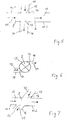
- FIG. 4 corresponds largely to that of FIG. 3 , However, here no bypass in the secondary branch 7 is provided and also not a pipe socket 18 which projects into the main channel 15.
- the first axial section 15.1 of the main channel 15 is parallel to the axis, in particular aligned with the second axial section 15.2. Furthermore, the flow channel 16 of the flow 11 is parallel to the axis or in alignment with the return channel 17 of the return 12th
- FIG. 6 is shown a way to the supply channel 16 in parallel, but offset from the return channel 17 to position. This prevents that flowing from the return line 12 in the main channel 15 cooling medium immediately flows back into the flow 11.
- FIG. 7 corresponds largely to that of FIG. 5
- the flow channel 16 and the return channel 17 are not perpendicular, but at an angle on the main channel 15th
- FIGS. 5 and 7 is indicated that the flow cross-sections of the flow channel 16 and in particular of the entire flow 11 and / or the flow cross-section of the return channel 17 and in particular the entire return 12 can at least substantially correspond to the flow cross-section of the main channel 15.
- the flow cross-sections according to the FIGS. 3, 4 and 6 it is indicated that they have a comparatively smaller flow cross-section.
- this can also be provided differently in the embodiments shown in each case.
- FIG. 8 an embodiment is shown in which the flow channel 16 is enclosed in the circumferential direction of the second axial portion 15.2 of the main channel 15 and the return channel 17 of the return line 12 opens into an annular channel 20 on the main channel 15.
- the cooling medium pump 1 has a spiral channel 1.1, in which the pump impeller 1.2 conveys the cooling medium. Both the flow 11 and the return 12 are connected to the spiral channel 1.1, that is, the flow 11 branches off from this and the return 12 opens into this one, and immediately adjacent to each other ,
- the flow cross-section of the spiral channel 1.1 increases with increasing run length of the spiral channel 1.1, that is with increasing length of the spiral channel 1.1 in the flow direction of the working medium, as increasingly more cooling medium, which emerges over the circumference of the pump impeller 1.2, is collected.
- the mouth of the return 12 can be a nozzle for the hydrodynamic retarder (in the FIG. 9 not shown) have exiting cooling medium, so that through the spiral channel 1.1 flowing cooling medium is entrained in the manner of a water jet pump.
- the hydrodynamic retarder exerts a significant pumping effect on the cooling medium during braking operation, so that a corresponding conveying effect is produced at the nozzle.
- the idea of forming a nozzle at the end of the return of the hydrodynamic retarder can also be carried out independently of the positioning of the return in the cooling circuit in terms of its relative position to the flow.
- Deviating from the representation in the FIG. 9 could also be the return 12 in the flow direction of the cooling medium through the spiral channel 1.1 in front of the flow 11 in the spiral channel 1.1 open, optionally in the form of a nozzle which extends partially or completely over the inflow of the flow 11.
- the main channel 15 at the junction 14 of the return 12 has a smaller flow cross-section than at the branch point 13 of the flow 11.
- the dynamic pressure in the main channel 15 at the branch point 13 due to the lower flow velocity of the cooling medium is smaller than at the junction point 14, whereby the static pressure is correspondingly greater.
Landscapes
- Engineering & Computer Science (AREA)
- Mechanical Engineering (AREA)
- General Engineering & Computer Science (AREA)
- Transportation (AREA)
- Chemical & Material Sciences (AREA)
- Combustion & Propulsion (AREA)
- Physics & Mathematics (AREA)
- Fluid Mechanics (AREA)
- Transmission Of Braking Force In Braking Systems (AREA)
- Motor Or Generator Cooling System (AREA)
- Braking Arrangements (AREA)
Description
- Die vorliegende Erfindung betrifft einen Kühlkreislauf für ein Kraftfahrzeug, in welchem ein hydrodynamischer Retarder angeordnet ist, im Einzelnen gemäß dem Oberbegriff von Anspruch 1.
- Neben sogenannten Ölretardern, die mit dem Arbeitsmedium Öl betrieben werden, das in einem eigenen Arbeitsmediumkreislauf des Retarders zirkuliert wird, sind sogenannte Wasserretarder bekannt, die unmittelbar in den Kühlkreislauf eines Kraftfahrzeugs eingebunden sind, der in der Regel mit Wasser oder einem Wassergemisch als Kühlmedium betrieben wird. Demgemäß ist das Arbeitsmedium des Retarders zugleich das Kühlmedium des Kühlkreislaufs.
- Während bei den erstgenannten Ölretardern ein zusätzlicher Wärmetauscher vorgesehen sein muss, um die im Bremsbetrieb des hydrodynamischen Retarders entstehende Wärme aus dem Arbeitsmedium abzuführen, beispielsweise in den Kühlkreislauf des Kraftfahrzeugs, kann bei den zweitgenannten Wasserretardern ein solcher separater Wärmetauscher entfallen, da die Wärme des hydrodynamischen Retarders im Retarder unmittelbar vom Kühlmedium aufgenommen wird und somit über den ohnehin vorgesehenen Wärmetauscher des Kühlkreislaufs (Fahrzeugkühler) abgeführt werden kann.
- Beispiele für solche in den Kühlkreislauf des Kraftfahrzeugs eingebundene hydrodynamische Retarder, wie sie die vorliegende Erfindung betrifft, werden in den folgenden Druckschriften offenbart:
- In der Praxis hat sich nun als nachteilig erwiesen, dass durch die Einbindung des hydrodynamischen Retarders unmittelbar in den Fahrzeugkühlkreislauf ein erhöhter durch die Kühlmediumpumpe zu überwindender Strömungswiderstand für das Kühlmedium auftreten kann. Somit wird in ungünstigen Fällen der Einsatz einer Kühlmediumpumpe mit einer vergleichsweise größeren Leistung im Vergleich zu Kühlkreisläufen ohne hydrodynamischen Retarder erforderlich. Gemäß der
EP 1 646 771 B1 werden daher verschiedene Maßnahmen vorgeschlagen, um die Notwendigkeit einer leistungsstärkeren Kühlmediumpumpe, die zu einem erhöhten Kraftstoffverbrauch führen kann, zu vermeiden. -
WO 97/33077 - Aufgrund der zunehmenden Bedeutung einer möglichst geringen Leistungsaufnahme der Kühlmediumpumpe besteht trotz der bereits vorgeschlagenen Maßnahmen ein Bedarf, den Strömungswiderstand in einem Kühlkreislauf für ein Kraftfahrzeug mit einem unmittelbar eingebundenen hydrodynamischen Retarder zu reduzieren.
- Der vorliegenden Erfindung liegt daher die Aufgabe zugrunde, einen Kühlkreislauf für ein Kraftfahrzeug anzugeben, der eine besonders verlustarme Einbindung des hydrodynamischen Retarders in den Kühlkreislauf ermöglicht.
- Die erfindungsgemäße Aufgabe wird durch einen Kühlkreislauf für ein Kraftfahrzeug mit den Merkmalen von Anspruch 1 gelöst. In den abhängigen Ansprüchen sind vorteilhafte und besonders zweckmäßige Ausgestaltungen der Erfindung angegeben.
- Der erfindungsgemäße Kühlkreislauf für ein Kraftfahrzeug weist eine Kühlmediumpumpe auf, die ein Kühlmedium im Kühlkreislauf umwälzt. Ferner ist ein hydrodynamischer Retarder vorgesehen, umfassend ein beschaufeltes Primärrad und ein beschaufeltes Sekundärrad, die gemeinsam einen mit einem Arbeitsmedium befüllbaren Arbeitsraum ausbilden. In dem Arbeitsraum kann durch Antreiben des Primärrades eine hydrodynamische Kreislaufströmung des Arbeitsmediums erzeugt werden, mittels welcher Antriebsleistung hydrodynamisch vom Primärrad auf das Sekundärrad übertragen wird, wodurch das Primärrad abgebremst wird. Das Sekundärrad kann als nicht umlaufender Stator oder als in Gegenrichtung zum Primärrad umlaufender Rotor vorgesehen sein.
- Erfindungsgemäß ist das Kühlmedium des Kühlkreislaufes zugleich Arbeitsmedium des hydrodynamischen Retarders.
- Der Kühlkreislauf weist einen Hauptkreis auf, in welchem die Kühlmediumpumpe positioniert ist. Ferner ist im Hauptkreis ein Antriebsmotor und/oder ein anderes Aggregat des Kraftfahrzeugs vorgesehen, der/das mittels des Kühlmediums gekühlt wird. Schließlich ist ein Wärmetauscher zur Abfuhr der vom Antriebsmotor oder dem anderen Aggregat aufgenommenen Wärme des Kühlmediums im Hauptkreis positioniert, sodass durch Antreiben der Kühlmediumpumpe, die vorteilhaft hierzu in einer Triebverbindung mit dem Antriebsmotor steht oder auch durch einen anderen Motor angetrieben werden kann, das Kühlmedium im Hauptkreis umgewälzt werden kann, um zunächst die Wärme in dem Antriebsmotor und/oder dem anderen Aggregat aufzunehmen und anschließend in dem Wärmetauscher beispielsweise an die Umgebung oder an einen Sekundärkreislauf abzugeben.
- Erfindungsgemäß ist der hydrodynamische Retarder in einem Nebenzweig des Kühlkreislaufes positioniert. Der Nebenzweig umfasst einen Vorlauf, der aus dem Hauptkreis an einer Abzweigstelle abzweigt und im hydrodynamischen Retarder mündet, sowie einen Rücklauf, der vom hydrodynamischen Retarder ausgeht und an einer Einmündungsstelle im Hauptkreis mündet. Somit kann Kühlmedium als Arbeitsmedium des hydrodynamischen Retarders vom Hauptkreis abgezweigt werden, über den Vorlauf in den Arbeitsraum des hydrodynamischen Retarders geleitet werden und in der Regel nach Durchlaufen der hydrodynamischen Kreislaufströmung aus dem Arbeitsraum des hydrodynamischen Retarders über den Rücklauf wieder dem Hauptkreis zugeführt werden.
- Erfindungsgemäß mündet der Rücklauf in Strömungsrichtung des Kühlmediums im Hauptkreis gesehen stromaufwärts der Abzweigstelle des Vorlaufes oder an der Abzweigstelle des Vorlaufes im Hauptkreis. Das bedeutet, es ist nicht, wie bisher üblich, eine Mündung des Rücklaufes stromabwärts der Abzweigstelle des Vorlaufes vorgesehen, sondern allenfalls im Bereich eines gemeinsamen Knotens der Abzweigstelle und der Mündungsstelle im Hauptkreis. Wenn der Rücklauf in Strömungsrichtung des Kühlmediums im Hauptkreis gesehen stromaufwärts der Abzweigstelle des Vorlaufes mündet, so sind jedoch die Mündung des Rücklaufes und die Abzweigstelle des Vorlaufes auf einer gemeinsamen Seite der Kühlmediumpumpe im Hauptkreis positioniert, das heißt entweder gemeinsam stromabwärts der Kühlmediumpumpe, das heißt auf deren Druckseite, oder gemeinsam stromaufwärts der Kühlmediumpumpe, das heißt auf deren Saugseite.
- Unter einem solchen gemeinsamen Knoten beziehungsweise einer Mündung des Rücklaufes an der Abzweigstelle des Vorlaufes sind alle solche Ausgestaltungen zu verstehen, bei denen die Mündung im selben axialen Abschnitt des Hauptkreises wie die Abzweigstelle vorgesehen ist. In der Regel wird dabei der Strömungsquerschnitt der Mündung und der Strömungsquerschnitt der Abzweigung nicht zusammenfallen, sondern beispielsweise über dem Umfang des Strömungsquerschnittes des Hauptkreises versetzt zueinander vorgesehen sein. Auch ist es möglich, im Hauptkreis im Bereich der Mündungsstelle und der Abzweigstelle einen Sammelquerschnitt vorzusehen, sodass beispielsweise der Vorlauf in Strömungsrichtung des Kühlmediums im Hauptkreis gesehen axial neben dem Rücklauf abzweigt, oberhalb von diesem oder unterhalb von diesem.
- Gemäß einer vorteilhaften Ausgestaltung der Erfindung ist vorgesehen, dass die Abzweigstelle des Vorlaufes im Hauptkreis frei von einem die Strömung in den Vorlauf umlenkenden Ventil, insbesondere frei von jeglichem Ventil ist. Zusätzlich oder alternativ kann auch die Einmündungsstelle des Rücklaufs im Hauptkreis frei von einem die Strömung im Rücklauf einstellenden Ventil, insbesondere frei von jeglichem Ventil sein.
- Besonders günstig ist es, wenn zumindest im Bereich der Einmündungsstelle und der Abzweigstelle der Hauptkreis durch einen Hauptkanal, der Vorlauf durch einen Vorlaufkanal und der Rücklauf durch einen Rücklaufkanal gebildet werden, wobei die verschiedenen Kanäle beispielsweise in einem gemeinsamen Bauteil, insbesondere Gussbauteil, integriert sein können, und ein erster axialer Abschnitt des Hauptkanals, der in Strömungsrichtung des Kühlmediums im Hauptkreis gesehen unmittelbar stromaufwärts der Abzweigstelle positioniert ist, parallel zur Axialrichtung eines axialen Abschnitts des Vorlaufkanals, der sich unmittelbar an die Abzweigstelle anschließt, verläuft, insbesondere mit diesem fluchtet. Eine Weiterbildung dieser Ausgestaltung sieht vor, dass ein zweiter axialer Abschnitt des Hauptkanals, der in Strömungsrichtung des Kühlmediums im Hauptkreis gesehen unmittelbar stromabwärts der Abzweigstelle positioniert ist, den axialen Abschnitt des Vorlaufkanals in Umfangsrichtung umschließt oder von diesem in Umfangsrichtung umschlossen wird.
- Eine Ausführungsform sieht vor, dass ein zweiter axialer Abschnitt des Hauptkanals, der in Strömungsrichtung des Kühlmediums im Hauptkreis gesehen unmittelbar stromabwärts der Abzweigstelle positioniert ist, parallel zu Axialrichtung eines axialen Abschnitts des Rücklaufkanals, der sich unmittelbar an die Einmündungsstelle anschließt, verläuft, insbesondere mit diesem fluchtet.
- Eine weitere vorteilhafte erfindungsgemäße Ausgestaltung sieht vor, dass, wie zuvor dargestellt, zumindest im Bereich der Einmündungsstelle und der Abzweigstelle der Hauptkreis durch einen Hauptkanal, der Vorlauf durch einen Vorlaufkanal und der Rücklauf durch einen Rücklaufkanal gebildet werden und nun abweichend ein erster axialer Abschnitt des Hauptkanals, der in Strömungsrichtung des Kühlmediums im Hauptkreis gesehen unmittelbar stromaufwärts der Abzweigstelle positioniert ist, parallel zur Axialrichtung eines zweiten axialen Abschnitts des Hauptkanals, der in Strömungsrichtung des Kühlmediums im Hauptkreis gesehen unmittelbar stromabwärts der Abzweigstelle positioniert ist, verläuft, insbesondere mit diesem fluchtet.
- Eine weitere vorteilhafte Ausführungsform ergibt sich, wenn ein axialer Abschnitt des Vorlaufkanals, der sich unmittelbar an die Abzweigstelle anschließt, parallel zur Axialrichtung eines axialen Abschnitts des Rücklaufkanals, der sich unmittelbar an die Einmündungsstelle anschließt, verläuft, insbesondere mit diesem fluchtet. Eine Weiterbildung sieht vor, dass der axiale Abschnitt des Rücklaufkanals in Axialrichtung versetzt zu dem axialen Abschnitt des Vorlaufkanals ist, insbesondere unterhalb oder oberhalb von diesem positioniert ist.
- Der erste axiale Abschnitt und der zweite axiale Abschnitt des Hauptkanals können sich unmittelbar aneinander anschließen und einen linearen querschnittsgleichen Strömungskanal ausbilden, insbesondere mit kreisrundem oder elliptischem Querschnitt. Bei dieser Ausgestaltung zweigt somit der Vorlauf winklig oder senkrecht aus einem rohrförmigen Kanal ab. Auch der Rücklauf kann entsprechend in diesem Strömungskanal einmünden, stromaufwärts der Abzweigstelle oder im Bereich der Abzweigstelle beziehungsweise an der Abzweigstelle.
- Gemäß einer vorteilhaften Ausführungsform weist der Vorlauf einen kleineren Strömungsquerschnitt als der Hauptkreis auf, zumindest bezogen auf den Strömungsquerschnitt des Hauptkreises im Bereich der Abzweigstelle. Auch der Rücklauf kann zusätzlich oder alternativ einen kleineren Strömungsquerschnitt als der Hauptkreis aufweisen, insbesondere bezogen auf den Strömungsquerschnitt des Hauptkreises an der Einmündungsstelle. Alternativ kann der Strömungsquerschnitt des Vorlaufes und/oder des Rücklaufes und insbesondere des gesamten Nebenzweigs auch größer als der Strömungsquerschnitt des Hauptkreises zumindest im Bereich der Abzweigstelle sein.
- Eine Ausführungsform sieht vor, dass die Abzweigstelle und die Einmündungsstelle in Strömungsrichtung des Kühlmediums im Hauptkreis hinter der Kühlmediumpumpe und somit auf deren Druckseite positioniert sind. Dabei kann die Strecke im Hauptkreis zwischen der Kühlmediumpumpe und der Abzweigstelle sowie der Einmündung frei von einem strömungsregelnden Organ und/oder einem zu kühlenden Aggregat beziehungsweise dem Antriebsmotor sein.
- Eine Ausführungsform sieht vor, dass die Abzweigstelle und die Einmündungsstelle in Strömungsrichtung des Kühlmediums im Hauptkreis vor dem Antriebsmotor oder dem anderen durch das Kühlmedium gekühlte Aggregat positioniert sind. Auch hier kann vorgesehen sein, dass zwischen der Abzweigstelle beziehungsweise der Einmündungsstelle und dem Antriebsmotor beziehungsweise dem anderen Aggregat kein strömungsregelndes Ventil und/oder ein anderes zu kühlendes Aggregat vorgesehen ist.
- Gemäß einer beispielhaften Ausführungsform mündet der Rücklauf in einem Rohrstutzen in dem Hauptkreis, wobei das Mündungsende des Rohrstutzens in die Kühlmediumströmung im Hauptkreis hineinragt. Somit ist die Mündungsstelle nicht unmittelbar am äußeren Umfang des Strömungsquerschnitts des Hauptkreises vorgesehen, sondern weiter in Richtung der Mitte des Strömungsquerschnittes des Hauptkreises. Hierdurch kann, wie später anhand eines Ausführungsbeispiels erläutert wird, das aus dem Rücklauf austretende Kühlmedium vollständig oder zumindest weitgehend über den Einlassquerschnitt des Vorlaufes hinweg geleitet werden.
- Im Nebenzweig des Kühlkreislaufes mit dem hydrodynamischen Retarder kann ein Bypass zur Umgehung des hydrodynamischen Retarders vorgesehen sein, der aus dem Vorlauf abzweigt und in den Rücklauf einmündet. Der Bypass und insbesondere die Abzweigstelle und/oder die Einmündungsstelle des Bypasses kann/können frei von strömungsregelnden Ventilen oder jeglichen Ventilen sein.
- Im Vorlauf kann ein Abschaltventil zur wahlweisen Freigabe oder Absperrung des Strömungsquerschnittes für das Kühlmedium zum hydrodynamischen Retarder vorgesehen sein. Ein solches Abschaltventil kann insbesondere als schwarz-weiß schaltendes Ventil ausgeführt sein, das heißt keine Zwischenstellungen zur teilweisen Absperrung des Strömungsquerschnittes aufweisen.
- Im Rücklauf kann ein Regelventil zur variablen Einstellung des Strömungsquerschnittes für das Kühlmedium aus dem Retarder vorgesehen sein. Dieses Regelventil weist vorteilhaft Zwischenstellungen zur teilweisen Absperrung des Strömungsquerschnittes sowie eine Stellung zur vollständigen Absperrung des Strömungsquerschnittes und eine Stellung zur vollständigen Freigabe des Strömungsquerschnittes auf und ist beispielsweise als stetigregelndes Ventil ausgeführt.
- Die Erfindung soll nachfolgend anhand verschiedener Ausführungsbeispiele exemplarisch beschrieben werden.
- Es zeigen:
- Figur 1
- ein erstes Ausführungsbeispiel eines erfindungsgemäßen Kühlkreislaufes mit einem über eine Knotenstelle angeschlossenen hydrodynamischen Retarder;
- Figur 2
- eine Ausführungsform der Erfindung, bei welcher der Rücklauf stromaufwärts der Abzweigstelle des Vorlaufes am Hauptkreis angeschlossen ist;
- Figur 3
- ein Ausführungsbeispiel für eine Knotenstelle zum Anschluss des Nebenzweigs mit dem hydrodynamischen Retarder am Hauptkreis;
- Figur 4
- ein weiteres Ausführungsbeispiel zur Gestaltung der Knotenstelle;
- Figur 5
- eine Ausgestaltung der Knotenstelle, sodass der Hauptzweig im Bereich der Knotenstelle linear ausgeführt werden kann;
- Figur 6
- eine mögliche Positionierung des Vorlaufs in Axialrichtung parallel, jedoch versetzt zum Rücklauf;
- Figur 7
- ein Beispiel einer Knotenstelle mit nicht senkrechtem Verlauf des Vorlaufs und Rücklaufs zum Hauptzweig;
- Figur 8
- ein Ausführungsbeispiel, bei welchem der Vorlauf konzentrisch vom Strömungskanal des Hauptzweigs umschlossen wird;
- Figur 9
- ein Ausführungsbeispiel, bei welchem der Vorlauf und der Rücklauf an dem Spiralkanal der Kühlmediumpumpe auf deren Druckseite angeschlossen sind;
- Figur 10
- ein Ausführungsbeispiel mit verschiedenen Strömungsquerschnitten des Hauptkanals an der Abzweigstelle und der Einmündungsstelle.
- In der
Figur 1 ist schematisch ein Kühlkreislauf eines Kraftfahrzeugs dargestellt, in welchem eine Kühlmediumpumpe 1 ein Kühlmedium durch einen Hauptkreis 2 pumpt, in dem neben der Kühlmediumpumpe 1 ein Antriebsmotor 3 und ein Wärmetauscher 4 vorgesehen sind. Wie durch die gestrichelte Linie angedeutet ist, kann die Kühlmediumpumpe 1 beispielweise mittels des Antriebsmotors 3 angetrieben werden, der ferner hier nicht näher dargestellte Antriebsräder des Kraftfahrzeugs antreibt. - Das im Antriebsmotor 3 erwärmte Kühlmedium wird im Wärmetauscher 4 abgekühlt. Im gezeigten Ausführungsbeispiel ist ein über ein Thermostatventil 5 ansteuerbarer Wärmetauscherbypass 6 im Hauptkreis 2 des Kühlkreislaufs vorgesehen.
- In einem Nebenzweig 7 ist ein hydrodynamischer Retarder 8 positioniert, der mit dem Kühlmedium als Arbeitsmedium betrieben wird. In Strömungsrichtung des Kühlmediums im Nebenzweig 7 ist vor (stromaufwärts) des hydrodynamischen Retarders 8 ein Abschaltventil 9 vorgesehen, mittels welchem der Strömungsquerschnitt in einem Vorlauf 11, der zum hydrodynamischen Retarder 8 führt, wahlweise abgesperrt oder geöffnet werden kann. In Strömungsrichtung des Kühlmediums im Nebenzweig 7 hinter (stromabwärts) des hydrodynamischen Retarders 8 ist ein Regelventil 10 vorgesehen, mittels welchem der Strömungsquerschnitt für Kühlmedium aus dem hydrodynamischen Retarder 8 und somit im Rücklauf 12 variabel eingestellt werden kann, um das Bremsmoment des hydrodynamischen Retarders 8 zu variieren.
- Bei dem in der
Figur 1 gezeigten Ausführungsbeispiel mündet der Rücklauf 12 an jener Stelle im Hauptkreis 2, an welcher auch die Abzweigstelle 13 des Vorlaufes 11 vorgesehen ist. Somit kann ein Bypass im Hauptkreis 2 zum hydrodynamischen Retarder 8 vermieden werden, der die strömungsführende axiale Länge des Hauptkreises 2 verlängern würde und damit zu einem vergleichsweise größeren Strömungsverlust führen würde. - Die Ausführungsform gemäß der
Figur 2 entspricht weitgehend jener derFigur 1 und sich entsprechende Bauteile sind mit denselben Bezugszeichen beziffert. Abweichend mündet jedoch hier der Rücklauf 12 in Strömungsrichtung des Kühlmediums im Hauptkreis 2 gesehen stromaufwärts der Abzweigstelle 13 des Vorlaufes 11. Bei der hier beispielhaft dargestellten Positionierung der Einmündungsstelle 14 und der Abzweigstelle 13 auf der Druckseite der Kühlmediumpumpe 1 ist demnach die Einmündungsstelle 14 des Rücklaufes 12 dichter an der Kühlmediumpumpe 1 positioniert als die Abzweigstelle 13. Bei der Ausführungsform gemäß derFigur 1 hingegen waren die Einmündungsstelle 14 und die Abzweigstelle 13 in etwa oder genau gleich weit von der Kühlmediumpumpe 1 entfernt. - Auch bei der Ausführungsform gemäß der
Figur 2 ist kein Bypass im Hauptkreis 2 zum hydrodynamischen Retarder 8 vorgesehen, durch welchen ein nicht durch den hydrodynamischen Retarder 8 strömender Anteil des Kühlmediums am hydrodynamischen Retarder 8 vorbeigeleitet wird. - Anhand der
Figuren 3 bis 8 sollen nun beispielhaft mögliche Ausgestaltungen von Knotenstellen erläutert werden, das heißt Ausführungsformen, bei welchen die Einmündungsstelle 14 an der Abzweigstelle 13 im Hauptkreis 2 positioniert ist. Die dargestellten Ausführungsformen könnten jedoch auch abweichend mit einer Positionierung der Einmündungsstelle 14 stromaufwärts der Abzweigstelle 13 im Hauptkreis 2 ausgeführt werden. - Bei allen im Folgenden diskutierten Ausgestaltungen wird der Hauptkreis 2 im Bereich der Abzweigstelle 13 und der Einmündungsstelle 14 durch einen Hauptkanal 15 gebildet, der einen ersten axialen Abschnitt 15.1 in Strömungsrichtung des Kühlmediums im Hauptkreis 2 unmittelbar stromaufwärts der Abzweigstelle 13 und einen zweiten axialen Abschnitt 15.2 in Strömungsrichtung des Kühlmediums im Hauptkreis 2 unmittelbar stromabwärts der Abzweigstelle 13 aufweist. Der Vorlauf 11 wird durch einen Vorlaufkanal 16 gebildet und der Rücklauf 12 wird durch einen Rücklaufkanal 17 gebildet.
- Gemäß der
Figur 3 ist die Axialrichtung des Vorlaufkanals 16 des Vorlaufes 11 parallel, insbesondere fluchtend zur Axialrichtung des ersten axialen Abschnitts 15.1 des Hauptkanals 15 positioniert, und die Axialrichtung des Rücklaufkanals 17 des Rücklaufes 12 ist parallel, insbesondere fluchtend zur Axialrichtung des zweiten axialen Abschnittes 15.2 des Hauptkanals 15 ausgerichtet, jeweils bezogen auf den axialen Abschnitt des Vorlaufkanals 16 beziehungsweise des Rücklaufkanals 17, der sich unmittelbar an die Abzweigstelle 13 beziehungsweise die Einmündungsstelle 14 anschließt. - Bei dem in der
Figur 3 dargestellten Ausführungsbeispiel weist der Rücklaufkanal 17 ferner einen Rohrstutzen 18 auf, dessen Mündungsende in die Kühlmediumströmung im Hauptkreis 2, das heißt im ersten axialen Abschnitt 15.1 des Hauptkanals 15 hineinragt. Der Rohrstutzen 18 kann dabei derart weit in den ersten axialen Abschnitt 15.1 hineinragen, dass er die Strömungsfläche der Abzweigstelle 13 teilweise oder vollständig überdeckt, um so zu verhindern, dass das aus dem Rücklauf 12 ausströmende Kühlmedium sofort wieder in den Vorlauf 11 einströmt und stattdessen weiter durch den Hauptkreis 2 strömt, nämlich in den zweiten axialen Abschnitt 15.2 des Hauptkanals 15. - Bei der in der
Figur 3 dargestellten Ausführungsform ist beispielhaft ferner ein Bypass 19 im Nebenzweig 7 vorgesehen, durch welchen jenes Kühlmedium des Nebenzweigs 7 strömen kann, das nicht durch den hydrodynamischen Retarder 8 geleitet wird. - In der
Figur 3 ist der Aufbau des Retarders 8 mit einem Primärrad 21 und einem Sekundärrad 22 schematisch dargestellt. Das Primärrad 21 und das Sekundärrad 22 stehen sich in Axialrichtung gegenüber und schließen in ihrem beschaufelten Bereich einen Arbeitsraum 23 zwischen sich ein. - Die Ausführungsform gemäß der
Figur 4 entspricht weitgehend jener derFigur 3 . Jedoch ist hier kein Bypass im Nebenzweig 7 vorgesehen und ebenso wenig ein Rohrstutzen 18, der in den Hauptkanal 15 hineinragt. - Gemäß der Ausgestaltung, die in der
Figur 5 dargestellt ist, ist der erste axiale Abschnitt 15.1 des Hauptkanals 15 achsparallel, insbesondere fluchtend zum zweiten axialen Abschnitt 15.2. Ferner ist der Vorlaufkanal 16 des Vorlaufs 11 achsparallel oder fluchtend zum Rücklaufkanal 17 des Rücklaufes 12. - In der
Figur 6 ist eine Möglichkeit dargestellt, um den Vorlaufkanal 16 parallel, jedoch versetzt zum Rücklaufkanal 17 zu positionieren. Hierdurch wird verhindert, dass aus dem Rücklauf 12 in den Hauptkanal 15 einströmendes Kühlmedium sofort wieder in den Vorlauf 11 strömt. - Die Ausgestaltung der
Figur 7 entspricht weitgehend jener derFigur 5 , jedoch stehen der Vorlaufkanal 16 und der Rücklaufkanal 17 nicht senkrecht, sondern winklig auf dem Hauptkanal 15. - In den
Figuren 5 und 7 ist angedeutet, dass die Strömungsquerschnitte des Vorlaufkanals 16 und insbesondere des gesamten Vorlaufes 11 und/oder der Strömungsquerschnitt des Rücklaufkanals 17 und insbesondere des gesamten Rücklaufes 12 zumindest im Wesentlichen dem Strömungsquerschnitt des Hauptkanals 15 entsprechen können. Bei den Ausführungsformen gemäß derFiguren 3, 4 und6 hingegen ist angedeutet, dass diese einen vergleichsweise kleineren Strömungsquerschnitt aufweisen. Dies kann jedoch in den jeweils gezeigten Ausgestaltungen auch anders vorgesehen sein. - In der
Figur 8 ist ein Ausführungsbeispiel dargestellt, bei welchem der Vorlaufkanal 16 in Umfangsrichtung vom zweiten axialen Abschnitt 15.2 des Hauptkanals 15 umschlossen wird und der Rücklaufkanal 17 des Rücklaufes 12 in einem Ringkanal 20 am Hauptkanal 15 mündet. - Gemäß der
Figur 9 weist die Kühlmediumpumpe 1 einen Spiralkanal 1.1 auf, in welchen das Pumpenlaufrad 1.2 das Kühlmedium fördert. Über den Spiralkanal 1.1 verlässt das Kühlmedium die Kühlmediumpumpe 1. Sowohl der Vorlauf 11 als auch der Rücklauf 12 sind an dem Spiralkanal 1.1 angeschlossen, das heißt der Vorlauf 11 zweigt von diesem ab und der Rücklauf 12 mündet in diesem ein, und zwar unmittelbar benachbart zueinander. - Der Strömungsquerschnitt des Spiralkanals 1.1 nimmt mit zunehmender Lauflänge des Spiralkanals 1.1, das heißt mit zunehmender Länge des Spiralkanals 1.1 in Strömungsrichtung des Arbeitsmediums, zu, da zunehmend mehr Kühlmedium, das über dem Umfang aus dem Pumpenlaufrad 1.2 austritt, gesammelt wird.
- Wie durch die gestrichelte Linie angedeutet ist, kann die Mündung des Rücklaufs 12 eine Düse für das aus dem hydrodynamischen Retarder (in der
Figur 9 nicht gezeigt) austretende Kühlmedium aufweisen, sodass das durch den Spiralkanal 1.1 strömende Kühlmedium nach Art einer Wasserstrahlpumpe mitgerissen wird. Der hydrodynamische Retarder übt im Bremsbetrieb nämlich eine erhebliche Pumpwirkung auf das Kühlmedium aus, sodass eine entsprechende Förderwirkung an der Düse entsteht. - Der Gedanke des Ausbildens einer Düse am Ende des Rücklaufes des hydrodynamischen Retarders kann auch unabhängig von der Positionierung des Rücklaufes im Kühlkreislauf auch hinsichtlich seiner relativen Lage zum Vorlauf ausgeführt werden.
- Abweichend von der Darstellung in der
Figur 9 könnte ferner der Rücklauf 12 in Strömungsrichtung des Kühlmediums durch den Spiralkanal 1.1 vor dem Vorlauf 11 im Spiralkanal 1.1 münden, gegebenenfalls in Form einer Düse, die teilweise oder vollständig über den Einströmquerschnitt des Vorlaufes 11 hinwegreicht. - Gemäß der
Figur 10 weist der Hauptkanal 15 an der Einmündungsstelle 14 des Rücklaufes 12 einen kleineren Strömungsquerschnitt als an der Abzweigstelle 13 des Vorlaufes 11 auf. Hierdurch ist der dynamische Druck im Hauptkanal 15 an der Abzweigstelle 13 aufgrund der geringeren Strömungsgeschwindigkeit des Kühlmediums kleiner als an der Einmündungsstelle 14, wodurch der statische Druck entsprechend größer ist. Dies begünstigt eine Durchströmung des Nebenzweigs mit dem hydrodynamischen Retarder (in derFigur 10 nicht im Einzelnen dargestellt).
Claims (19)
- Kühlkreislauf für ein Kraftfahrzeug1.1 mit einer Kühlmediumpumpe (1), die ein Kühlmedium im Kühlkreislauf umwälzt;1.2 mit einem hydrodynamischen Retarder (8), umfassend ein beschaufeltes Primärrad (21) und ein beschaufeltes Sekundärrad (22), die gemeinsam einen mit einem Arbeitsmedium befüllbaren Arbeitsraum (23) ausbilden, wobei das Arbeitsmedium das Kühlmedium ist; und1.3 der Kühlkreislauf einen Hauptkreis (2) aufweist, in welchem die Kühlmediumpumpe (1) und ein Antriebsmotor (3) des Kraftfahrzeugs oder ein anderes Aggregat zur Kühlung mittels des Kühlmediums, sowie ein Wärmetauscher (4) zur Abfuhr der vom Antriebsmotor (3) oder dem anderen Aggregat aufgenommenen Wärme des Kühlmediums positioniert sind; wobei1.4 die Kühlmediumpumpe (1) das Kühlmedium im Hauptkreis (2) umwälzt; und1.5 der hydrodynamische Retarder (8) in einem Nebenzweig (7) des Kühlkreislaufes positioniert ist, umfassend einen Vorlauf (11), der aus dem Hauptkreis (2) an einer Abzweigstelle (13) abzweigt und im hydrodynamischen Retarder (8) mündet, und einen Rücklauf (12), der vom hydrodynamischen Retarder (8) ausgeht und an einer Einmündungsstelle (14) im Hauptkreis (2) mündet;
dadurch gekennzeichnet, dass1.6 der Rücklauf (12) in Strömungsrichtung des Kühlmediums im Hauptkreis (2) gesehen stromaufwärts der Abzweigstelle (13) des Vorlaufes (11), jedoch auf derselben Seite der Kühlmediumpumpe (1) mündet, oder an der Abzweigstelle (13) des Vorlaufes (11) im Hauptkreis (2) mündet. - Kühlkreislauf gemäß Anspruch 1, dadurch gekennzeichnet, dass die Abzweigstelle (13) des Vorlaufes (11) im Hauptkreis (2) frei von einem die Strömung in den Vorlauf (11) umlenkenden Ventil, insbesondere frei von jeglichem Ventil ist.
- Kühlkreislauf gemäß einem der Ansprüche 1 oder 2, dadurch gekennzeichnet, dass die Einmündungsstelle (14) des Rücklaufes (12) im Hauptkreis (2) frei von einem die Strömung im Rücklauf (12) einstellenden Ventil, insbesondere frei von jeglichem Ventil ist.
- Kühlkreislauf gemäß einem der Ansprüche 1 bis 3, dadurch gekennzeichnet, dass zumindest im Bereich der Einmündungsstelle (14) und der Abzweigstelle (13) der Hauptkreis (2) durch einen Hauptkanal (15), der Vorlauf (11) durch einen Vorlaufkanal (16) und der Rücklauf (12) durch einen Rücklaufkanal (17) gebildet werden und ein erster axialer Abschnitt (15.1) des Hauptkanals (15), der in Strömungsrichtung des Kühlmediums im Hauptkreis (2) gesehen unmittelbar stromaufwärts der Abzweigstelle (13) positioniert ist, parallel zur Axialrichtung eines axialen Abschnittes des Vorlaufkanals (16), der sich unmittelbar an die Abzweigstelle (13) anschließt, verläuft, insbesondere mit diesem fluchtet.
- Kühlkreislauf gemäß Anspruch 4, dadurch gekennzeichnet, dass ein zweiter axialer Abschnitt (15.2) des Hauptkanals (15), der in Strömungsrichtung des Kühlmediums im Hauptkreis (2) gesehen unmittelbar stromabwärts der Abzweigstelle (13) positioniert ist, den axialen Abschnitt des Vorlaufkanals (16) in Umfangsrichtung umschließt oder von diesem in Umfangsrichtung umschlossen wird.
- Kühlkreislauf gemäß Anspruch 4, dadurch gekennzeichnet, dass ein zweiter axialer Abschnitt (15.2) des Hauptkanals (15), der in Strömungsrichtung des Kühlmediums im Hauptkreis (2) gesehen unmittelbar stromabwärts der Abzweigstelle (13) positioniert ist, parallel zur Axialrichtung eines axialen Abschnitts des Rücklaufkanals (17), der sich unmittelbar an die Einmündungsstelle (14) anschließt, verläuft, insbesondere mit diesem fluchtet.
- Kühlkreislauf gemäß einem der Ansprüche 1 bis 3, dadurch gekennzeichnet, dass zumindest im Bereich der Einmündungsstelle (13) und der Abzweigstelle (14) der Hauptkreis (2) durch einen Hauptkanal (15), der Vorlauf (11) durch einen Vorlaufkanal (16) und der Rücklauf (12) durch einen Rücklaufkanal (17) gebildet werden und ein erster axialer Abschnitt (15.1) des Hauptkanals (15), der in Strömungsrichtung des Kühlmediums im Hauptkreis (2) gesehen unmittelbar stromaufwärts der Abzweigstelle (13) positioniert ist, parallel zur Axialrichtung eines zweiten axialen Abschnitts (15.2) des Hauptkanals (15), der in Strömungsrichtung des Kühlmediums im Hauptkreis (2) gesehen unmittelbar stromabwärts der Abzweigstelle (13) positioniert ist, verläuft, insbesondere mit diesem fluchtet.
- Kühlkreislauf gemäß einem der Ansprüche 1 bis 3 und insbesondere gemäß Anspruch 7, dadurch gekennzeichnet, dass ein axialer Abschnitt des Vorlaufkanals (16), der sich unmittelbar an die Abzweigstelle (13) anschließt, parallel zur Axialrichtung eines axialen Abschnitts des Rücklaufkanals (17), der sich unmittelbar an die Einmündungsstelle (14) anschließt, verläuft, insbesondere mit diesem fluchtet.
- Kühlkreislauf gemäß Anspruch 8, dadurch gekennzeichnet, dass der axiale Abschnitt des Rücklaufkanals (17) in Axialrichtung versetzt zu dem axialen Abschnitt des Vorlaufkanals (16) ist, insbesondere unterhalb oder oberhalb von diesem positioniert ist.
- Kühlkreislauf gemäß einem der Ansprüche 7 bis 9, dadurch gekennzeichnet, dass der erste axiale Abschnitt (15.1) und der zweite axiale Abschnitt (15.2) des Hauptkanals (15) sich unmittelbar aneinander anschließend einen linearen querschnittsgleichen Strömungskanal ausbilden, insbesondere mit kreisrundem oder elliptischem Querschnitt.
- Kühlkreislauf gemäß einem der Ansprüche 1 bis 10, dadurch gekennzeichnet, dass der Vorlauf (11) und/oder der Rücklauf (12) einen kleineren Strömungsquerschnitt aufweisen als der Hauptkreis (2).
- Kühlkreislauf gemäß einem der Ansprüche 1 bis 11, dadurch gekennzeichnet, dass die Abzweigstelle (13) und die Einmündungsstelle (14) in Strömungsrichtung des Kühlmediums im Hauptkreis (2) hinter der Kühlmediumpumpe (1) positioniert sind.
- Kühlkreislauf gemäß einem der Ansprüche 1 bis 12, dadurch gekennzeichnet, dass die Abzweigstelle (13) und die Einmündungsstelle (14) in Strömungsrichtung des Kühlmediums im Hauptkreis (2) vor dem Antriebsmotor (3) oder dem anderen Aggregat positioniert sind.
- Kühlkreislauf gemäß einem der Ansprüche 1 bis 13, dadurch gekennzeichnet, dass der Rücklauf (12) in einem Rohrstutzen (18) in den Hauptkreis (2) mündet, dessen Mündungsende in die Kühlmediumströmung im Hauptkreis (2) hineinragt.
- Kühlkreislauf gemäß einem der Ansprüche 1 bis 14, dadurch gekennzeichnet, dass im Nebenzweig (7) des Kühlkreislaufes mit dem hydrodynamischen Retarder (8) ein Bypass (19) zur Umgehung des hydrodynamischen Retarders (8) vorgesehen ist, der aus dem Vorlauf (11) abzweigt und in den Rücklauf (12) einmündet und insbesondere frei von strömungsregelnden Ventilen oder jeglichen Ventilen ist.
- Kühlkreislauf gemäß einem der Ansprüche 1 bis 15, dadurch gekennzeichnet, dass im Vorlauf (11) ein Abschaltventil (9) zur wahlweisen Freigabe oder Absperrung des Strömungsquerschnittes für Kühlmedium zum hydrodynamischen Retarder (8) vorgesehen ist.
- Kühlkreislauf gemäß einem der Ansprüche 1 bis 16, dadurch gekennzeichnet, dass im Rücklauf (12) ein Regelventil (10) zur variablen Einstellung des Strömungsquerschnittes für Kühlmedium aus dem hydrodynamischen Retarder (8) vorgesehen ist.
- Kühlkreislauf gemäß einem der Ansprüche 1 bis 17, dadurch gekennzeichnet, dass der Rücklauf (12) und der Vorlauf (11) gemeinsam an einem Spiralkanal (1.1) der Kühlmediumpumpe (1) angeschlossen sind.
- Kühlkreislauf gemäß einem der Ansprüche 1 bis 16, dadurch gekennzeichnet, dass der Hauptkreis (2) an der Abzweigstelle (13) des Vorlaufes (11) einen größeren Strömungsquerschnitt als an der Einmündungsstelle (14) des Rücklaufes (12) aufweist.
Applications Claiming Priority (2)
| Application Number | Priority Date | Filing Date | Title |
|---|---|---|---|
| DE102013001657.6A DE102013001657A1 (de) | 2013-01-31 | 2013-01-31 | Kühlkreislauf für ein Kraftfahrzeug mit einem hydrodynamischen Retarder |
| PCT/EP2014/051594 WO2014118158A1 (de) | 2013-01-31 | 2014-01-28 | Kühlkreislauf für ein kraftfahrzeug mit einem hydrodynamischen retarder |
Publications (2)
| Publication Number | Publication Date |
|---|---|
| EP2951066A1 EP2951066A1 (de) | 2015-12-09 |
| EP2951066B1 true EP2951066B1 (de) | 2017-03-22 |
Family
ID=50023571
Family Applications (1)
| Application Number | Title | Priority Date | Filing Date |
|---|---|---|---|
| EP14701551.5A Active EP2951066B1 (de) | 2013-01-31 | 2014-01-28 | Kühlkreislauf für ein kraftfahrzeug mit einem hydrodynamischen retarder |
Country Status (7)
| Country | Link |
|---|---|
| US (1) | US9650023B2 (de) |
| EP (1) | EP2951066B1 (de) |
| CN (1) | CN105008188B (de) |
| BR (1) | BR112015017132A8 (de) |
| DE (1) | DE102013001657A1 (de) |
| RU (1) | RU2637058C2 (de) |
| WO (1) | WO2014118158A1 (de) |
Cited By (1)
| Publication number | Priority date | Publication date | Assignee | Title |
|---|---|---|---|---|
| DE102022119963A1 (de) | 2022-08-09 | 2024-02-15 | Voith Patent Gmbh | Motor mit integriertem Retarder |
Families Citing this family (6)
| Publication number | Priority date | Publication date | Assignee | Title |
|---|---|---|---|---|
| DE102013219786A1 (de) * | 2013-09-30 | 2015-04-02 | Voith Patent Gmbh | Hydrauliksystem für eine hydrodynamische Maschine |
| CN107781330B (zh) * | 2017-11-17 | 2024-02-20 | 潍柴动力股份有限公司 | 整车匹配液力缓速器的散热系统及汽车 |
| CN111520226A (zh) * | 2019-02-02 | 2020-08-11 | 陕西重型汽车有限公司 | 一种智能化缓速器冷却控制系统及控制方法 |
| CN112441040B (zh) * | 2019-09-04 | 2022-04-01 | 中铁十六局集团有限公司 | 机车用热能循环系统 |
| DE102019124328A1 (de) * | 2019-09-11 | 2021-03-11 | Bayerische Motoren Werke Aktiengesellschaft | Kühlvorrichtung, Elektromotor und Werkzeugmaschine |
| CN115158248B (zh) * | 2022-07-05 | 2023-07-14 | 一汽解放汽车有限公司 | 缓速器的冷却系统及其控制方法、车辆 |
Family Cites Families (14)
| Publication number | Priority date | Publication date | Assignee | Title |
|---|---|---|---|---|
| DE1530672A1 (de) | 1963-09-03 | 1969-10-30 | Eaton Yale & Towne | Hydrodynamische Bremseinrichtung fuer Kraftfahrzeuge |
| DE4447166A1 (de) | 1994-12-30 | 1995-06-08 | Voith Turbo Kg | Bremsanlage mit einem hydrodynamischen Retarder, insbesondere für ein Kraftfahrzeug |
| US6561324B2 (en) * | 1996-03-08 | 2003-05-13 | Voith Turbo Gmbh & Co. Kg | Drive unit including a motor and a retarder |
| EP0794326A1 (de) * | 1996-03-08 | 1997-09-10 | Voith Turbo GmbH & Co. KG | Antriebseinheit mit einem Motor und einem Retarder |
| DE19616427C2 (de) | 1996-04-25 | 1997-08-28 | Voith Turbo Kg | Antriebseinheit mit einem Motor und einem Retarder |
| DE29707304U1 (de) | 1997-04-23 | 1998-08-27 | Voith Turbo GmbH & Co. KG, 89522 Heidenheim | Vorrichtung zur maximalen Ausnutzung der Bremswirkung eines Retarders |
| RU2216467C2 (ru) * | 2001-02-07 | 2003-11-20 | Военный автомобильный институт | Гидродинамический тормоз-замедлитель автомобиля |
| DE10118856A1 (de) | 2001-04-18 | 2002-10-24 | Zahnradfabrik Friedrichshafen | Bremsanlage mit einem Retarder |
| DE10332907A1 (de) * | 2003-07-19 | 2005-02-17 | Voith Turbo Gmbh & Co. Kg | Kraftfahrzeugkühlmittelkreislauf mit Pumpe und Retarder |
| DE102006054615B3 (de) * | 2006-11-17 | 2007-12-20 | Voith Patent Gmbh | Kühlsystem mit einem Antriebsmotor und einer hydrodynamischen Maschine |
| DE102007006420A1 (de) * | 2007-02-05 | 2008-08-07 | Voith Patent Gmbh | Kraftfahrzeugantriebsstrang eines Kraftfahrzeugs mit einem Druckluftsystem |
| DE102009035082A1 (de) * | 2009-07-28 | 2011-02-10 | Voith Patent Gmbh | Getriebeölkreislauf |
| DE102009055975A1 (de) * | 2009-11-27 | 2011-06-01 | Voith Patent Gmbh | Kühlsystem, insbesondere eines Kraftfahrzeugs |
| DE102010051717A1 (de) * | 2010-11-19 | 2012-05-24 | Voith Patent Gmbh | Antriebsstrang mit einem hydrodynamischen Retarder und Verfahren zum Einstellen des Bremsmomentes |
-
2013
- 2013-01-31 DE DE102013001657.6A patent/DE102013001657A1/de not_active Withdrawn
-
2014
- 2014-01-28 EP EP14701551.5A patent/EP2951066B1/de active Active
- 2014-01-28 RU RU2015136534A patent/RU2637058C2/ru active
- 2014-01-28 CN CN201480006977.2A patent/CN105008188B/zh active Active
- 2014-01-28 BR BR112015017132A patent/BR112015017132A8/pt not_active Application Discontinuation
- 2014-01-28 WO PCT/EP2014/051594 patent/WO2014118158A1/de not_active Ceased
-
2015
- 2015-07-31 US US14/814,850 patent/US9650023B2/en active Active
Non-Patent Citations (1)
| Title |
|---|
| None * |
Cited By (1)
| Publication number | Priority date | Publication date | Assignee | Title |
|---|---|---|---|---|
| DE102022119963A1 (de) | 2022-08-09 | 2024-02-15 | Voith Patent Gmbh | Motor mit integriertem Retarder |
Also Published As
| Publication number | Publication date |
|---|---|
| BR112015017132A2 (pt) | 2017-07-11 |
| US20160068142A1 (en) | 2016-03-10 |
| US9650023B2 (en) | 2017-05-16 |
| CN105008188A (zh) | 2015-10-28 |
| RU2637058C2 (ru) | 2017-11-29 |
| BR112015017132A8 (pt) | 2019-10-29 |
| EP2951066A1 (de) | 2015-12-09 |
| DE102013001657A1 (de) | 2014-07-31 |
| CN105008188B (zh) | 2017-09-22 |
| RU2015136534A (ru) | 2017-03-07 |
| WO2014118158A1 (de) | 2014-08-07 |
Similar Documents
| Publication | Publication Date | Title |
|---|---|---|
| EP2951066A1 (de) | Kühlkreislauf für ein kraftfahrzeug mit einem hydrodynamischen retarder | |
| EP2300696B1 (de) | Getriebeölkreislauf | |
| DE102013008967B4 (de) | Vorrichtung zum Abdichten einer Schiffspropellerwelle sowie Verfahren zur Herstellung einer derartigen Vorrichtung | |
| WO2008058578A1 (de) | Kühlsystem mit einem antriebsmotor und einer hydrodynamischen maschine | |
| EP1646771B1 (de) | Kraftfahrzeugk hlmittelkreislauf mit pumpe und retarder | |
| DE102006045034A1 (de) | Wassergekühlte Konstanttemperatur-Flüssigkeitszirkuliervorrichtung und Verfahren zur Steuerung der Temperatur der zirkulierenden Flüssigkeit | |
| DE102022002863A1 (de) | Axialflussmaschine, insbesondere für ein Kraftfahrzeug | |
| WO2010081728A1 (de) | Fahrzeugkühlkreislauf mit einem retarder oder einer hydrodynamischen kupplung | |
| EP2726785A1 (de) | Umleitdampfleitung | |
| DE102007013843A1 (de) | Gerät und Verfahren zur Kontrolle von Leckage bei Dampfturbinen | |
| EP1702820B1 (de) | Kühlkreislauf mit einer hydrodynamischen Bremse | |
| EP1292760B1 (de) | Konfiguration einer kühlbaren turbinenschaufel | |
| DE102011015196B4 (de) | Heizung zur Erwärmung von Betriebsstoffen für Fahrzeuge sowie entsprechendes Schienenfahrzeug | |
| DE102007055604B3 (de) | Fahrzeugkühlkreislauf mit einem hydrodynamischen Retarder | |
| DE102010035393B4 (de) | Turbine und Verfahren zum Betrieb einer Turbine für ein CAES-System | |
| DE102008013675B4 (de) | Innere Gestaltung des Gehäuses einer Kühlmittelpumpe mit mehreren Auslasskanälen | |
| DE10054078A1 (de) | Restentleerung | |
| EP3849859A1 (de) | Hydrodynamischer retarder | |
| EP3597879B1 (de) | Landwirtschaftliche maschine mit einem kühlsystem | |
| DE102017000201B4 (de) | Hydraulischer Lüfterantrieb, Arbeitsmaschine sowie Verfahren zum Betreiben eines Lüfterantriebs | |
| DE102024131807A1 (de) | Kreiselpumpe mit einer Leitvorrichtung | |
| DE102016209169A1 (de) | Axialkolbenmaschine, insbesondere für ein Kraftfahrzeug | |
| DE102024131828A1 (de) | Kreiselpumpe mit einer Leitvorrichtung | |
| EP3114364B1 (de) | Staudruckpumpe für eine hydrodynamische maschine | |
| DE102023121395A1 (de) | Heizanordnung für einen Kühlkreislauf und Kühlkreislauf für ein Kraftfahrzeug |
Legal Events
| Date | Code | Title | Description |
|---|---|---|---|
| PUAI | Public reference made under article 153(3) epc to a published international application that has entered the european phase |
Free format text: ORIGINAL CODE: 0009012 |
|
| 17P | Request for examination filed |
Effective date: 20150831 |
|
| AK | Designated contracting states |
Kind code of ref document: A1 Designated state(s): AL AT BE BG CH CY CZ DE DK EE ES FI FR GB GR HR HU IE IS IT LI LT LU LV MC MK MT NL NO PL PT RO RS SE SI SK SM TR |
|
| AX | Request for extension of the european patent |
Extension state: BA ME |
|
| RIN1 | Information on inventor provided before grant (corrected) |
Inventor name: MANDLIK, MANFRED Inventor name: STURM, DIETMAR Inventor name: BAUER, THOMAS Inventor name: BECK, MANFRED Inventor name: MENNE, ACHIM Inventor name: GOTTSCHALL, MATTHIAS Inventor name: ADAMS, WERNER |
|
| DAX | Request for extension of the european patent (deleted) | ||
| GRAP | Despatch of communication of intention to grant a patent |
Free format text: ORIGINAL CODE: EPIDOSNIGR1 |
|
| INTG | Intention to grant announced |
Effective date: 20161012 |
|
| GRAS | Grant fee paid |
Free format text: ORIGINAL CODE: EPIDOSNIGR3 |
|
| GRAA | (expected) grant |
Free format text: ORIGINAL CODE: 0009210 |
|
| AK | Designated contracting states |
Kind code of ref document: B1 Designated state(s): AL AT BE BG CH CY CZ DE DK EE ES FI FR GB GR HR HU IE IS IT LI LT LU LV MC MK MT NL NO PL PT RO RS SE SI SK SM TR |
|
| REG | Reference to a national code |
Ref country code: GB Ref legal event code: FG4D Free format text: NOT ENGLISH |
|
| REG | Reference to a national code |
Ref country code: CH Ref legal event code: EP |
|
| REG | Reference to a national code |
Ref country code: AT Ref legal event code: REF Ref document number: 877398 Country of ref document: AT Kind code of ref document: T Effective date: 20170415 |
|
| REG | Reference to a national code |
Ref country code: IE Ref legal event code: FG4D Free format text: LANGUAGE OF EP DOCUMENT: GERMAN |
|
| REG | Reference to a national code |
Ref country code: DE Ref legal event code: R096 Ref document number: 502014003110 Country of ref document: DE |
|
| REG | Reference to a national code |
Ref country code: NL Ref legal event code: FP |
|
| REG | Reference to a national code |
Ref country code: SE Ref legal event code: TRGR |
|
| PG25 | Lapsed in a contracting state [announced via postgrant information from national office to epo] |
Ref country code: GR Free format text: LAPSE BECAUSE OF FAILURE TO SUBMIT A TRANSLATION OF THE DESCRIPTION OR TO PAY THE FEE WITHIN THE PRESCRIBED TIME-LIMIT Effective date: 20170623 Ref country code: FI Free format text: LAPSE BECAUSE OF FAILURE TO SUBMIT A TRANSLATION OF THE DESCRIPTION OR TO PAY THE FEE WITHIN THE PRESCRIBED TIME-LIMIT Effective date: 20170322 Ref country code: NO Free format text: LAPSE BECAUSE OF FAILURE TO SUBMIT A TRANSLATION OF THE DESCRIPTION OR TO PAY THE FEE WITHIN THE PRESCRIBED TIME-LIMIT Effective date: 20170622 Ref country code: HR Free format text: LAPSE BECAUSE OF FAILURE TO SUBMIT A TRANSLATION OF THE DESCRIPTION OR TO PAY THE FEE WITHIN THE PRESCRIBED TIME-LIMIT Effective date: 20170322 Ref country code: LT Free format text: LAPSE BECAUSE OF FAILURE TO SUBMIT A TRANSLATION OF THE DESCRIPTION OR TO PAY THE FEE WITHIN THE PRESCRIBED TIME-LIMIT Effective date: 20170322 |
|
| REG | Reference to a national code |
Ref country code: LT Ref legal event code: MG4D |
|
| PG25 | Lapsed in a contracting state [announced via postgrant information from national office to epo] |
Ref country code: LV Free format text: LAPSE BECAUSE OF FAILURE TO SUBMIT A TRANSLATION OF THE DESCRIPTION OR TO PAY THE FEE WITHIN THE PRESCRIBED TIME-LIMIT Effective date: 20170322 Ref country code: BG Free format text: LAPSE BECAUSE OF FAILURE TO SUBMIT A TRANSLATION OF THE DESCRIPTION OR TO PAY THE FEE WITHIN THE PRESCRIBED TIME-LIMIT Effective date: 20170622 Ref country code: RS Free format text: LAPSE BECAUSE OF FAILURE TO SUBMIT A TRANSLATION OF THE DESCRIPTION OR TO PAY THE FEE WITHIN THE PRESCRIBED TIME-LIMIT Effective date: 20170322 |
|
| PG25 | Lapsed in a contracting state [announced via postgrant information from national office to epo] |
Ref country code: EE Free format text: LAPSE BECAUSE OF FAILURE TO SUBMIT A TRANSLATION OF THE DESCRIPTION OR TO PAY THE FEE WITHIN THE PRESCRIBED TIME-LIMIT Effective date: 20170322 Ref country code: RO Free format text: LAPSE BECAUSE OF FAILURE TO SUBMIT A TRANSLATION OF THE DESCRIPTION OR TO PAY THE FEE WITHIN THE PRESCRIBED TIME-LIMIT Effective date: 20170322 Ref country code: SK Free format text: LAPSE BECAUSE OF FAILURE TO SUBMIT A TRANSLATION OF THE DESCRIPTION OR TO PAY THE FEE WITHIN THE PRESCRIBED TIME-LIMIT Effective date: 20170322 Ref country code: ES Free format text: LAPSE BECAUSE OF FAILURE TO SUBMIT A TRANSLATION OF THE DESCRIPTION OR TO PAY THE FEE WITHIN THE PRESCRIBED TIME-LIMIT Effective date: 20170322 Ref country code: CZ Free format text: LAPSE BECAUSE OF FAILURE TO SUBMIT A TRANSLATION OF THE DESCRIPTION OR TO PAY THE FEE WITHIN THE PRESCRIBED TIME-LIMIT Effective date: 20170322 |
|
| PG25 | Lapsed in a contracting state [announced via postgrant information from national office to epo] |
Ref country code: PL Free format text: LAPSE BECAUSE OF FAILURE TO SUBMIT A TRANSLATION OF THE DESCRIPTION OR TO PAY THE FEE WITHIN THE PRESCRIBED TIME-LIMIT Effective date: 20170322 Ref country code: IS Free format text: LAPSE BECAUSE OF FAILURE TO SUBMIT A TRANSLATION OF THE DESCRIPTION OR TO PAY THE FEE WITHIN THE PRESCRIBED TIME-LIMIT Effective date: 20170722 Ref country code: SM Free format text: LAPSE BECAUSE OF FAILURE TO SUBMIT A TRANSLATION OF THE DESCRIPTION OR TO PAY THE FEE WITHIN THE PRESCRIBED TIME-LIMIT Effective date: 20170322 Ref country code: PT Free format text: LAPSE BECAUSE OF FAILURE TO SUBMIT A TRANSLATION OF THE DESCRIPTION OR TO PAY THE FEE WITHIN THE PRESCRIBED TIME-LIMIT Effective date: 20170724 |
|
| REG | Reference to a national code |
Ref country code: DE Ref legal event code: R097 Ref document number: 502014003110 Country of ref document: DE |
|
| REG | Reference to a national code |
Ref country code: FR Ref legal event code: PLFP Year of fee payment: 5 |
|
| PLBE | No opposition filed within time limit |
Free format text: ORIGINAL CODE: 0009261 |
|
| STAA | Information on the status of an ep patent application or granted ep patent |
Free format text: STATUS: NO OPPOSITION FILED WITHIN TIME LIMIT |
|
| PG25 | Lapsed in a contracting state [announced via postgrant information from national office to epo] |
Ref country code: DK Free format text: LAPSE BECAUSE OF FAILURE TO SUBMIT A TRANSLATION OF THE DESCRIPTION OR TO PAY THE FEE WITHIN THE PRESCRIBED TIME-LIMIT Effective date: 20170322 |
|
| 26N | No opposition filed |
Effective date: 20180102 |
|
| PG25 | Lapsed in a contracting state [announced via postgrant information from national office to epo] |
Ref country code: SI Free format text: LAPSE BECAUSE OF FAILURE TO SUBMIT A TRANSLATION OF THE DESCRIPTION OR TO PAY THE FEE WITHIN THE PRESCRIBED TIME-LIMIT Effective date: 20170322 |
|
| REG | Reference to a national code |
Ref country code: CH Ref legal event code: PL |
|
| GBPC | Gb: european patent ceased through non-payment of renewal fee |
Effective date: 20180128 |
|
| PG25 | Lapsed in a contracting state [announced via postgrant information from national office to epo] |
Ref country code: MT Free format text: LAPSE BECAUSE OF FAILURE TO SUBMIT A TRANSLATION OF THE DESCRIPTION OR TO PAY THE FEE WITHIN THE PRESCRIBED TIME-LIMIT Effective date: 20170322 |
|
| PG25 | Lapsed in a contracting state [announced via postgrant information from national office to epo] |
Ref country code: LU Free format text: LAPSE BECAUSE OF NON-PAYMENT OF DUE FEES Effective date: 20180128 |
|
| REG | Reference to a national code |
Ref country code: IE Ref legal event code: MM4A |
|
| REG | Reference to a national code |
Ref country code: BE Ref legal event code: MM Effective date: 20180131 |
|
| PG25 | Lapsed in a contracting state [announced via postgrant information from national office to epo] |
Ref country code: CH Free format text: LAPSE BECAUSE OF NON-PAYMENT OF DUE FEES Effective date: 20180131 Ref country code: LI Free format text: LAPSE BECAUSE OF NON-PAYMENT OF DUE FEES Effective date: 20180131 Ref country code: BE Free format text: LAPSE BECAUSE OF NON-PAYMENT OF DUE FEES Effective date: 20180131 Ref country code: GB Free format text: LAPSE BECAUSE OF NON-PAYMENT OF DUE FEES Effective date: 20180128 |
|
| PG25 | Lapsed in a contracting state [announced via postgrant information from national office to epo] |
Ref country code: IE Free format text: LAPSE BECAUSE OF NON-PAYMENT OF DUE FEES Effective date: 20180128 |
|
| PG25 | Lapsed in a contracting state [announced via postgrant information from national office to epo] |
Ref country code: MC Free format text: LAPSE BECAUSE OF FAILURE TO SUBMIT A TRANSLATION OF THE DESCRIPTION OR TO PAY THE FEE WITHIN THE PRESCRIBED TIME-LIMIT Effective date: 20170322 |
|
| REG | Reference to a national code |
Ref country code: DE Ref legal event code: R081 Ref document number: 502014003110 Country of ref document: DE Owner name: VOITH PATENT GMBH, DE Free format text: FORMER OWNERS: MAN TRUCK & BUS AG, 80995 MUENCHEN, DE; VOITH PATENT GMBH, 89522 HEIDENHEIM, DE Ref country code: DE Ref legal event code: R081 Ref document number: 502014003110 Country of ref document: DE Owner name: MAN TRUCK & BUS SE, DE Free format text: FORMER OWNERS: MAN TRUCK & BUS AG, 80995 MUENCHEN, DE; VOITH PATENT GMBH, 89522 HEIDENHEIM, DE |
|
| REG | Reference to a national code |
Ref country code: AT Ref legal event code: MM01 Ref document number: 877398 Country of ref document: AT Kind code of ref document: T Effective date: 20190128 |
|
| PG25 | Lapsed in a contracting state [announced via postgrant information from national office to epo] |
Ref country code: TR Free format text: LAPSE BECAUSE OF FAILURE TO SUBMIT A TRANSLATION OF THE DESCRIPTION OR TO PAY THE FEE WITHIN THE PRESCRIBED TIME-LIMIT Effective date: 20170322 |
|
| PG25 | Lapsed in a contracting state [announced via postgrant information from national office to epo] |
Ref country code: AT Free format text: LAPSE BECAUSE OF NON-PAYMENT OF DUE FEES Effective date: 20190128 |
|
| PG25 | Lapsed in a contracting state [announced via postgrant information from national office to epo] |
Ref country code: CY Free format text: LAPSE BECAUSE OF FAILURE TO SUBMIT A TRANSLATION OF THE DESCRIPTION OR TO PAY THE FEE WITHIN THE PRESCRIBED TIME-LIMIT Effective date: 20170322 Ref country code: MK Free format text: LAPSE BECAUSE OF NON-PAYMENT OF DUE FEES Effective date: 20170322 Ref country code: HU Free format text: LAPSE BECAUSE OF FAILURE TO SUBMIT A TRANSLATION OF THE DESCRIPTION OR TO PAY THE FEE WITHIN THE PRESCRIBED TIME-LIMIT; INVALID AB INITIO Effective date: 20140128 |
|
| PG25 | Lapsed in a contracting state [announced via postgrant information from national office to epo] |
Ref country code: AL Free format text: LAPSE BECAUSE OF FAILURE TO SUBMIT A TRANSLATION OF THE DESCRIPTION OR TO PAY THE FEE WITHIN THE PRESCRIBED TIME-LIMIT Effective date: 20170322 |
|
| PGFP | Annual fee paid to national office [announced via postgrant information from national office to epo] |
Ref country code: NL Payment date: 20260121 Year of fee payment: 13 |
|
| PGFP | Annual fee paid to national office [announced via postgrant information from national office to epo] |
Ref country code: SE Payment date: 20260121 Year of fee payment: 13 |
|
| REG | Reference to a national code |
Ref country code: DE Ref legal event code: R081 Ref document number: 502014003110 Country of ref document: DE Owner name: DRIVENTIC GMBH, DE Free format text: FORMER OWNERS: MAN TRUCK & BUS SE, 80995 MUENCHEN, DE; VOITH PATENT GMBH, 89522 HEIDENHEIM, DE Ref country code: DE Ref legal event code: R081 Ref document number: 502014003110 Country of ref document: DE Owner name: MAN TRUCK & BUS SE, DE Free format text: FORMER OWNERS: MAN TRUCK & BUS SE, 80995 MUENCHEN, DE; VOITH PATENT GMBH, 89522 HEIDENHEIM, DE |
|
| PGFP | Annual fee paid to national office [announced via postgrant information from national office to epo] |
Ref country code: DE Payment date: 20260121 Year of fee payment: 13 |
|
| PGFP | Annual fee paid to national office [announced via postgrant information from national office to epo] |
Ref country code: IT Payment date: 20260126 Year of fee payment: 13 |
|
| PGFP | Annual fee paid to national office [announced via postgrant information from national office to epo] |
Ref country code: FR Payment date: 20260123 Year of fee payment: 13 |