EP2948359B1 - Schienenfahrzeug mit neigetechnik - Google Patents
Schienenfahrzeug mit neigetechnik Download PDFInfo
- Publication number
- EP2948359B1 EP2948359B1 EP14701013.6A EP14701013A EP2948359B1 EP 2948359 B1 EP2948359 B1 EP 2948359B1 EP 14701013 A EP14701013 A EP 14701013A EP 2948359 B1 EP2948359 B1 EP 2948359B1
- Authority
- EP
- European Patent Office
- Prior art keywords
- car body
- tilting
- rail vehicle
- chassis
- gravity
- Prior art date
- Legal status (The legal status is an assumption and is not a legal conclusion. Google has not performed a legal analysis and makes no representation as to the accuracy of the status listed.)
- Active
Links
Images
Classifications
-
- B—PERFORMING OPERATIONS; TRANSPORTING
- B61—RAILWAYS
- B61F—RAIL VEHICLE SUSPENSIONS, e.g. UNDERFRAMES, BOGIES OR ARRANGEMENTS OF WHEEL AXLES; RAIL VEHICLES FOR USE ON TRACKS OF DIFFERENT WIDTH; PREVENTING DERAILING OF RAIL VEHICLES; WHEEL GUARDS, OBSTRUCTION REMOVERS OR THE LIKE FOR RAIL VEHICLES
- B61F5/00—Constructional details of bogies; Connections between bogies and vehicle underframes; Arrangements or devices for adjusting or allowing self-adjustment of wheel axles or bogies when rounding curves
- B61F5/38—Arrangements or devices for adjusting or allowing self- adjustment of wheel axles or bogies when rounding curves, e.g. sliding axles, swinging axles
- B61F5/44—Adjustment controlled by movements of vehicle body
-
- B—PERFORMING OPERATIONS; TRANSPORTING
- B61—RAILWAYS
- B61F—RAIL VEHICLE SUSPENSIONS, e.g. UNDERFRAMES, BOGIES OR ARRANGEMENTS OF WHEEL AXLES; RAIL VEHICLES FOR USE ON TRACKS OF DIFFERENT WIDTH; PREVENTING DERAILING OF RAIL VEHICLES; WHEEL GUARDS, OBSTRUCTION REMOVERS OR THE LIKE FOR RAIL VEHICLES
- B61F5/00—Constructional details of bogies; Connections between bogies and vehicle underframes; Arrangements or devices for adjusting or allowing self-adjustment of wheel axles or bogies when rounding curves
- B61F5/02—Arrangements permitting limited transverse relative movements between vehicle underframe or bolster and bogie; Connections between underframes and bogies
- B61F5/22—Guiding of the vehicle underframes with respect to the bogies
-
- B—PERFORMING OPERATIONS; TRANSPORTING
- B61—RAILWAYS
- B61D—BODY DETAILS OR KINDS OF RAILWAY VEHICLES
- B61D1/00—Carriages for ordinary railway passenger traffic
Definitions
- the invention relates to a rail vehicle with tilting technology.
- Such a rail vehicle is from, for example DE 195 22 378 A1 known.
- Tilting technology systems known from the prior art such as in EP 0619212 described, allow a curve inclination up to 8 °.
- the speed in curves can be increased by up to 30% without impairing driving comfort through increased lateral acceleration.
- Tilting systems can basically be designed as passive or as active systems.
- the car bodies are usually suspended above their center of gravity on elevated extensions of the chassis beam. Due to the centrifugal force, they swing outwards in the lower area and inwards in the upper area. The vibrations are calmed by damping elements.
- the tilt angle is limited to 3.5 °. As a result, the speed gain when traveling through bends is also significantly lower than with active systems, so passive tilting technology is primarily used to improve comfort.
- the object of the invention is to provide a tilting technology system which is more tolerant and simpler than the disadvantages mentioned.
- a rail vehicle with tilting technology in which the car body is mounted on at least two running gears, and in which at least one of the running gears is connected to the car body via an active tilting technology system, and at least one further running gear is connected to the via a passive tilting technology system Car body is connected.
- the advantage here is that not every undercarriage on which the car body is mounted must have an active tilting technology system. If, for example, there are two undercarriages per car body, one undercarriage with the active tilting technology system is sufficient. The inclination of the car body when the rail vehicle is traveling through the bend is then impressed exclusively by means of the one active tilting system.
- Another advantage is the possibility of easy and exact monitoring of the active tilt technology system using simple software. In addition, the effort for wiring the tilting system is reduced.
- the at least one undercarriage which is connected to the car body via the passive tilting technology system, preferably has an instantaneous pole that is as close as possible to the center of gravity of the car body, preferably in the center of gravity of the car body, in any tilted state of the car body.
- the instantaneous pole is the angular momentary axis of rotation of the car body. If the momentary pole of the passive tilt technology system is in the center of gravity of the car body in every tilt condition, there is no restoring torque. Is the momentary pole of the passive tilt technology system in any tilt condition As close as possible to the center of gravity of the car body, there is only a very low restoring torque.
- the instantaneous pole is preferably in the center of gravity of the car body.
- the tilted state of the car body can then only be returned to the horizontal basic state by external force - according to the invention by the active tilting system. In this case, no restoring torque is caused by gravity alone.
- the inclination of the car body is impressed solely by the chassis that is connected to the car body via the active tilting system.
- the at least one undercarriage which is connected to the car body via the active tilting technology system, has an instantaneous pole lying next to the line of gravity through the center of gravity of the car body in every tilting state of the car body.
- the car body is pivotably mounted on the at least one further running gear with a passive tilting system by means of rollers running in roller conveyors.
- car body is pivotally connected to the at least one running gear with an active tilting technology system by means of a pendulum mechanism.
- the car body can also be pivoted on all running gear with a passive tilting system and on all running gear with an active tilting system by means of rollers running in roller conveyors.
- Such bearings have the advantage that they have a very low rolling resistance.
- smaller, less powerful and less expensive actuators can be used on the chassis with the active tilting technology system compared to the prior art, which actuators convert the car body from the tilted state into the horizontal basic state and vice versa.
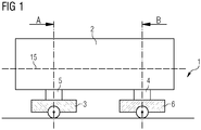
- the rail vehicle 1 shown has a first undercarriage 3 and a second undercarriage 6.
- a carriage body 2, which has a longitudinal axis 15, is mounted on the running gears 3, 6.
- the second undercarriage 6 is connected to the car body 2 via an active tilting technology system 4 and the first undercarriage 3 is connected to the car body 2 via a passive tilting technology system 5.
- the chassis 3 with the passive tilting technology system 5 follows the movements of the active tilting technology system 4, but it has no devices or actuators for actively supporting an inclination of the car body 2.
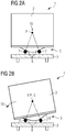
- FIG 2a the rail vehicle 1 is shown in section A.
- the car body 2 is pivotally mounted on the first chassis 3 with the passive tilting system 5 by means of rollers 7 running in roller conveyors 8.
- the car body 2 can be pivoted about the instantaneous pole P.
- the undercarriage 3 does not include any devices for actively supporting the inclination of the car body 2.
- the rail vehicle 1 is shown in a non-inclined state, the horizontal basic state.
- the roller tracks 8 are inclined in different directions so that their extensions intersect at one point like the legs of a V.
- the rollers 7 and the roller conveyors 8 are arranged essentially symmetrically to the longitudinal axis 15 or to a vertical plane through the longitudinal axis 15 of the car body 2.
- FIG 2b shows the rail vehicle 1 in section A with an inclined body 2.
- the body 2 is pivotally mounted on the first chassis 3 with the passive tilting system 5 by means of rollers 7 running in roller conveyors 8.
- the car body 2 can be pivoted about the instantaneous pole P.
- the body 2 is compared to the illustration in FIG 2a inclined in the first inclination direction 16, it is in the inclined state.
- the position of the instantaneous pole P does not change during the tilting process of the car body 2 - its position therefore coincides with the instantaneous pole P 'in every tilted state of the car body 2.
- the instantaneous pole P ' is the angular momentary axis of rotation of the car body 2 in the tilted state.
- the passive tilting technology system 5 has an instantaneous pole P, which is preferably in the center of gravity S of the car body 2 in every tilting state of the car body 2. In this case, no restoring moment is brought about by gravity, which returns the car body 2 to the horizontal basic state by the action of gravity. The tilted state of the car body 2 can only be returned to the basic state by external force.
- the inclination of the car body 2 is impressed solely by the second chassis 6 with the active tilting system 4.
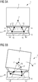
- the rail vehicle 1 is shown in section B.
- the second chassis 6 is connected to the car body 2 via the active tilting system 4.
- the active tilting technology system 4 is designed as a pendulum mechanism.
- the pendulum mechanism comprises two carrier elements 9 connected to the bottom of the car body 2.
- the carrier elements 9 have first joints 10, which realize a rotatable connection with pendulum elements 11.
- the pendulum elements 11 are connected to a cross member 13 so as to be rotatable via second joints 12.
- the cross member 13 is connected to the second chassis 6.
- Either the carrier elements 9 can be rigidly connected to the car body 2 or the crossmember 13 can be rigidly connected to the second undercarriage 6.
- Actuators 14 are provided between the crossmember 13 and the support elements 9, which cause the body 2 to tilt around the instantaneous pole P.
- the 3b shows the rail vehicle 1 in section B, but in an inclined state - in the inclined state.
- the second chassis 6 is connected to the car body 2 via the active tilting system 4.
- the car body 2 is inclined in the second inclination direction 17 - it is in the inclined state.
- the instantaneous pole P moves during the tilting process of the car body 2 in the second tilt direction 17 on a polar curve 18 from P to P '.
- the instantaneous pole P 'of the active tilting technology system 4 lies in every tilting state of the car body 2 in addition to the line of gravity through the center of gravity S of the car body 2. As a result, a restoring torque occurs in every tilting state, which acts in favor of the horizontal basic state of the car body 2.
- the car body 2 can also be pivotably mounted on all trolleys 3.6 with a passive tilting technology system 5 and on all trolleys 3.6 with an active tilting system 4 by means of rollers 7 running in roller conveyors 8.
- Such bearings have the advantage that they have a very low rolling resistance.
- smaller, less powerful and less expensive actuators 14 can be used on the chassis 6 with the active tilting technology system 4 compared to the prior art, which actuators convert the body 2 from the tilted state into the horizontal basic state and vice versa.
- the inclination of the car body 2 is determined exclusively by means of the active one Tilting system 4 stamped. This prevents the car body 2 from being twisted and loaded in an uncontrolled manner.
Landscapes
- Engineering & Computer Science (AREA)
- Mechanical Engineering (AREA)
- Transportation (AREA)
- Vehicle Body Suspensions (AREA)
Description
- Die Erfindung betrifft ein Schienenfahrzeug mit Neigetechnik.
- Ein solches Schienenfahrzeug ist z.B. aus der
DE 195 22 378 A1 bekannt. - Bei der Bogenfahrt eines Schienenfahrzeuges entsteht durch die Fliehkraft ein Moment, wodurch sich der Wagen in Richtung Außenseite des Bogens neigt. Infolge dieser Neigung dreht sich das Koordinatensystem auch für den im Wagenkasten befindlichen Fahrgast und ein Anteil der Erdbeschleunigung wirkt nunmehr als Seitenbeschleunigung, was als besonders störend empfunden wird.
- Insbesondere bei bogenschneller Fahrt mit hoher Querbeschleunigung am Radsatz werden ohne zusätzliche Maßnahmen die für den Fahrgast zulässigen Werte deutlich überschritten.
- Aus dem Stand der Technik ist die sogenannte Neigetechnik, eine gleisbogenabhängige Wagenkastensteuerung, bekannt, bei der die Wagenkästen eines Eisenbahnzuges zur Kurveninnenseite geneigt werden können wodurch die empfundene Seitenbeschleunigung reduziert wird.
- Damit können Gleisbögen ("bogenschnelles Fahren") schneller durchfahren oder die Kurvenfahrt kann für den Passagier angenehmer gestaltet ("Komfortneigung")werden.
- Aus dem Stand der Technik bekannte Neigetechniksysteme wie beispielsweise in der
EP 0619212 beschrieben, ermöglichen eine Kurvenneigung bis zu 8°. Damit kann ohne Beeinträchtigung des Fahrkomforts durch erhöhte Seitenbeschleunigung die Geschwindigkeit in Kurven um bis zu 30 % erhöht werden. - Neigetechniksysteme können grundsätzlich als passive oder als aktive Systeme ausgeführt sein.
- Bei der passiven Neigetechnik werden üblicherweise die Wagenkästen oberhalb ihres Schwerpunktes an erhöhten Fortsätzen des Fahrwerksträgers aufgehängt. Dadurch schwingen sie aufgrund der Fliehkraft im unteren Bereich nach außen, im oberen nach innen. Die Schwingungen werden durch Dämpfungselemente beruhigt. Der Neigewinkel ist auf 3,5° beschränkt. Dadurch ist der Geschwindigkeitsgewinn bei Bogenfahrt auch deutlich geringer als bei aktiven Systemen, passive Neigetechnik dient daher vorwiegend der Komfortverbesserung.
- Bei der aktiven Neigetechnik wird die Auslenkung der Wagenkästen mittels Aktuatoren, welche als hydraulische Stellzylinder oder als elektrische Stellantriebe ausgeführt sind, bewirkt. Dabei muss sichergestellt werden, dass die Wagenkästen bei einem Ausfall der Aktuatoren selbstständig von einem Neigezustand wieder in einen waagrechten Grundzustand (ready to run - Position) rückgeführt werden. Dies geschieht durch Auslegen der Fahrwerke in Bezug auf den Schwerpunkt und der Drehachse der Wagenkästen derart, dass im Neigezustand ein entsprechendes Rückstellmoment wirkt. Nachteilig dabei ist, dass dazu leistungsstarke Aktuatoren notwendig sind, da diese im Neigezustand der Wagenkästen gegen dieses Rückstellmoment wirken müssen.
- Aus der
DE 103 16 497 ist ein Schienenfahrzeug mit aktiver Neigetechnik bekannt, bei dem der Wagenkasten mittels Rollen und Rollenbahnen schwenkbar gelagert ist. - Wenn der Wagenkasten eines Schienenfahrzeuges auf zwei oder mehreren Fahrwerken mit aktiven Neigetechniksystemen gelagert ist, besteht die Gefahr, dass durch unterschiedliche Ansteuerung des Wagenkastens über die zwei oder mehreren aktiven Neigetechniksysteme dieser unkontrolliert verwindet und belastet wird. Durch die Verwindung werden überdies einzelne Räder entlastet, was im Extremfall zu einer Entgleisung bei der Bogenfahrt führen kann. Daher benötigen solche herkömmliche Neigetechniksysteme eine entsprechend aufwendige Überwachungseinrichtung.
- Der Erfindung liegt die Aufgabe zugrunde, ein gegenüber den genannten Nachteilen toleranteres und einfacheres Neigetechniksystem bereitzustellen.
- Diese Aufgabe wird erfindungsgemäß gelöst durch ein Schienenfahrzeug mit Neigetechnik, bei dem der Wagenkasten auf zumindest zwei Fahrwerken gelagert ist, und bei dem zumindest eines der Fahrwerke über ein aktives Neigetechniksystem mit dem Wagenkasten verbunden ist und wobei zumindest ein weiteres Fahrwerk über ein passives Neigetechniksystem mit dem Wagenkasten verbunden ist.
- Vorteilhaft dabei ist, dass nicht jedes Fahrwerk, auf dem der Wagenkasten gelagert ist, über ein aktives Neigetechniksystem verfügen muss. Bei Vorhandensein von beispielsweise zwei Fahrwerken pro Wagenkasten ist ein Fahrwerk mit dem aktiven Neigetechniksystem ausreichend. Die Neigung des Wagenkastens bei der Bogenfahrt des Schienenfahrzeugs wird dann ausschließlich mittels des einen aktiven Neigetechniksystems eingeprägt.
- Ein weiterer Vorteil ergibt sich durch die Möglichkeit einer leichten und exakten Überwachung des aktiven Neigetechniksystems mittels einfacher Software. Zusätzlich reduziert sich der Aufwand für die Verkabelung des Neigetechniksystems.
- Vorzugsweise weist das zumindest eine Fahrwerk, welches über das passive Neigetechniksystem mit dem Wagenkasten verbunden ist, einen Momentanpol auf, der sich in jedem Neigezustand des Wagenkastens möglichst nahe am Schwerpunkt des Wagenkastens, vorzugsweise im Schwerpunkt des Wagenkastens befindet.
- Unter Momentanpol ist die winkelmomentane Drehachse des Wagenkastens zu verstehen. Liegt der Momentanpol des passiven Neigetechniksystems in jedem Neigezustand im Schwerpunkt des Wagenkastens, so tritt kein Rückstellmoment auf. Liegt der Momentanpol des passiven Neigetechniksystems in jedem Neigezustand möglichst nahe am Schwerpunkt des Wagenkastens, so tritt nur ein sehr geringes Rückstellmoment auf.
- Vorzugsweise liegt der Momentanpol im Schwerpunkt des Wagenkastens. Der Neigezustand des Wagenkastens kann dann nur durch äußere Krafteinwirkung wieder in den waagrechten Grundzustand rückgeführt werden - erfindungsgemäß durch das aktive Neigetechniksystem. Allein durch die Schwerkraft wird in diesem Fall kein Rückstellmoment bewirkt. Bei der Beschreibung der Lage des Momentanpols und des Schwerpunkts ist von einer Betrachtungsweise normal zu einer Längsachse des Wagenkastens auszugehen.
- Die Neigung des Wagenkastens wird alleine durch jenes Fahrwerk eingeprägt, welches über das aktive Neigetechniksystem mit dem Wagenkasten verbunden ist.
- Vorteilhafterweise wird damit vermieden, dass der Wagenkasten unkontrolliert verwindet und belastet wird, wie es bei Fahrwerken, welche alle mit einem aktiven Neigetechniksystem ausgestattet sind, auftreten kann. Ein durch ein solches Verwinden auftretendes Sicherheitsrisiko durch Entlastung einzelner Räder bei der Bogenfahrt des Schienenfahrzeugs wird somit vermieden.
- In einer vorteilhaften Ausführungsform weist das zumindest eine Fahrwerk, welches über das aktive Neigetechniksystem mit dem Wagenkasten verbunden ist, in jedem Neigezustand des Wagenkastens einen neben der Wirkungslinie der Schwerkraft durch den Schwerpunkt des Wagenkastens liegenden Momentanpol auf.
- Liegt der Momentanpol des aktiven Neigetechniksystems in jedem Neigezustand des Wagenkastens neben der Wirkungslinie der Schwerkraft durch den Schwerpunkt des Wagenkastens, so tritt ein Rückstellmoment auf.
- Dadurch ist sichergestellt, dass der Wagenkasten bei Ausfall des aktiven Neigetechniksystems selbstständig durch Einwirkung der Schwerkraft vom Neigezustand in den waagrechten Grundzustand übergeführt wird.
- Bei der Beschreibung der Lage des Momentanpols und des Schwerpunkts ist von einer Betrachtungsweise normal zu einer Längsachse des Wagenkastens auszugehen.
- In einer vorteilhaften Ausgestaltung ist der Wagenkasten auf dem zumindest einen weiteren Fahrwerk mit passivem Neigetechniksystem mittels in Rollenbahnen laufenden Rollen schwenkbar gelagert.
- Eine weitere vorteilhafte Ausgestaltung ergibt sich dadurch, dass der Wagenkasten mit dem zumindest einem Fahrwerk mit aktivem Neigetechniksystem mittels einer Pendelmechanik schwenkbar verbunden ist.
- Der Wagenkasten kann auch auf allen Fahrwerken mit passivem Neigetechniksystem und auf allen Fahrwerken mit aktivem Neigetechniksystem mittels in Rollenbahnen laufenden Rollen schwenkbar gelagert sein.
- Derartige Lagerungen haben den Vorteil, dass sie einen sehr geringen Rollwiderstand aufweisen. Dadurch können am Fahrwerk mit dem aktiven Neigetechniksystem im Vergleich zum Stand der Technik kleinere, leistungsschwächere und kostengünstigere Aktuatoren eingesetzt werden, welche den Wagenkasten vom Neigezustand in den waagrechten Grundzustand und umgekehrt überführen.
- Die Erfindung wird anhand von Figuren näher erläutert.
- Es zeigen beispielhaft und schematisch:
-
FIG 1 ein erfindungsgemäßes Schienenfahrzeug mit Neigetechnik. -
FIG 2a eine Ansicht eines erfindungsgemäßen Schienenfahrzeugs im Schnitt A. -
FIG 2b eine Ansicht eines erfindungsgemäßen Schienenfahrzeugs mit geneigtem Wagenkasten im Schnitt A. -
FIG 3a eine Ansicht eines erfindungsgemäßen Schienenfahrzeugs im Schnitt B. -
FIG 3b eine Ansicht eines erfindungsgemäßen Schienenfahrzeugs mit geneigtem Wagenkasten im Schnitt B. - Das in
FIG 1 dargestellte Schienenfahrzeug 1 weist ein erstes Fahrwerk 3 und ein zweites Fahrwerk 6 auf. Auf den Fahrwerken 3,6 ist ein Wagenkasten 2, welcher eine Längsachse 15 aufweist, gelagert. Das zweite Fahrwerk 6 ist über ein aktives Neigetechniksystem 4 mit dem Wagenkasten 2 verbunden und das erste Fahrwerk 3 ist über ein passives Neigetechniksystem 5 mit dem Wagenkasten 2 verbunden. Bei der Bogenfahrt des Schienenfahrzeugs 1 wird die Neigung des Wagenkastens 2 ausschließlich mittels des aktiven Neigetechniksystems 4 eingeprägt. Das Fahrwerk 3 mit dem passiven Neigetechniksystem 5 folgt den Bewegungen des aktiven Neigetechniksystems 4, es verfügt aber über keine Einrichtungen beziehungsweise Aktuatoren zur aktiven Unterstützung einer Neigung des Wagenkastens 2. - In
FIG 2a ist das Schienenfahrzeug 1 im Schnitt A dargestellt. Der Wagenkasten 2 ist auf dem ersten Fahrwerk 3 mit dem passiven Neigetechniksystem 5 mittels in Rollenbahnen 8 laufenden Rollen 7 schwenkbar gelagert. Der Wagenkasten 2 ist um den Momentanpol P schwenkbar. Das Fahrwerk 3 umfasst keine Einrichtungen zur aktiven Unterstützung der Neigung des Wagenkastens 2. Das Schienenfahrzeug 1 ist in einem ungeneigten Zustand, dem waagrechten Grundzustand, dargestellt. Die Rollenbahnen 8 sind in unterschiedliche Richtungen geneigt, so dass sich ihre Verlängerungen wie die Schenkel eines V in einem Punkt schneiden. Die Rollen 7 sowie die Rollenbahnen 8 sind im wesentlichen symmetrisch zur Längsachse 15 beziehungsweise zu einer vertikalen Ebene durch die Längsachse 15 des Wagenkastens 2 angeordnet. -
FIG 2b zeigt das Schienenfahrzeug 1 im Schnitt A mit geneigtem Wagenkasten 2. Der Wagenkasten 2 ist auf dem ersten Fahrwerk 3 mit dem passiven Neigetechniksystem 5 mittels in Rollenbahnen 8 laufenden Rollen 7 schwenkbar gelagert. Der Wagenkasten 2 ist um den Momentanpol P schwenkbar. Der Wagenkasten 2 ist im Vergleich zur Darstellung inFIG 2a in die erste Neigerichtung 16 geneigt, er befindet sich im Neigezustand. Die Lage des Momentanpols P ändert sich während des Neigevorgangs des Wagenkastens 2 nicht - seine Lage deckt sich daher in jedem Neigezustand des Wagenkastens 2 mit dem Momentanpol P'. Der Momentanpol P' ist die winkelmomentane Drehachse des Wagenkastens 2 im Neigezustand. Das passive Neigetechniksystem 5 weist einen Momentanpol P auf, der sich in jedem Neigezustand des Wagenkastens 2 vorzugsweise im Schwerpunkt S des Wagenkastens 2 befindet. In diesem Fall wird durch die Schwerkraft kein Rückstellmoment bewirkt, welches den Wagenkasten 2 durch Schwerkrafteinwirkung wieder in den waagrechten Grundzustand rückführt. Der Neigezustand des Wagenkastens 2 kann nur durch äußere Krafteinwirkung wieder in den Grundzustand rückgeführt werden. - Die Neigung des Wagenkastens 2 wird alleine durch das zweite Fahrwerk 6 mit dem aktiven Neigetechniksystem 4 eingeprägt.
- In
FIG 3a ist das Schienenfahrzeug 1 im Schnitt B dargestellt. Das zweite Fahrwerk 6 ist über das aktive Neigetechniksystem 4 mit dem Wagenkasten 2 verbunden. Das aktive Neigetechniksystem 4 ist in dieser Ausführungsform als Pendelmechanik ausgeführt. Die Pendelmechanik umfasst zwei mit dem Boden des Wagenkastens 2 verbundene Trägerelemente 9. Die Trägerelemente 9 weisen erste Gelenke 10 auf, welche eine drehbewegliche Verbindung mit Pendelelementen 11 realisieren. Im Bereich ihrer den ersten Gelenken 10 abgewandten Ausdehnung sind die Pendelelemente 11 über zweite Gelenke 12 drehbeweglich mit einer Traverse 13 verbunden. Die Traverse 13 ist mit dem zweiten Fahrwerk 6 verbunden. Es können entweder die Trägerelemente 9 starr mit dem Wagenkasten 2 oder die Traverse 13 starr mit dem zweiten Fahrwerk 6 verbunden sein. Zwischen der Traverse 13 und den Trägerelementen 9 sind Aktuatoren 14 vorgesehen, die die Neigung des Wagenkastens 2 um den Momentanpol P bewirken. -
FIG 3b zeigt das Schienenfahrzeug 1 im Schnitt B, jedoch in einem geneigten Zustand - im Neigezustand. Das zweite Fahrwerk 6 ist über das aktive Neigetechniksystem 4 mit dem Wagenkasten 2 verbunden. Der Wagenkasten 2 ist in die zweite Neigerichtung 17 geneigt - er befindet sich im Neigezustand. Der Momentanpol P wandert während des Neigevorgangs des Wagenkastens 2 in die zweite Neigerichtung 17 auf einer Polkurve 18 von P nach P'. Der Momentanpol P' des aktiven Neigetechniksystems 4 liegt in jedem Neigezustand des Wagenkastens 2 neben der Wirkungslinie der Schwerkraft durch den Schwerpunkt S des Wagenkastens 2. Dadurch tritt in jedem Neigezustand ein Rückstellmoment auf, welches zugunsten des waagrechten Grundzustands des Wagenkastens 2 wirkt. - Dadurch ist sichergestellt, dass der Wagenkasten 2 bei Ausfall des aktiven Neigetechniksystems 4 selbstständig durch Einwirkung der Schwerkraft vom Neigezustand in den waagrechten Grundzustand übergeführt wird.
- Der Wagenkasten 2 kann auch auf allen Fahrwerken 3,6 mit passivem Neigetechniksystem 5 und auf allen Fahrwerken 3,6 mit aktivem Neigetechniksystem 4 mittels in Rollenbahnen 8 laufenden Rollen 7 schwenkbar gelagert sein.
- Derartige Lagerungen haben den Vorteil, dass sie einen sehr geringen Rollwiderstand aufweisen. Dadurch können am Fahrwerk 6 mit dem aktiven Neigetechniksystem 4 im Vergleich zum Stand der Technik kleinere, leistungsschwächere und kostengünstigere Aktuatoren 14 eingesetzt werden, welche den Wagenkasten 2 vom Neigezustand in den waagrechten Grundzustand und umgekehrt überführen.
- Mittels des erfindungsgemäßen Schienenfahrzeugs 1 wird die Neigung des Wagenkastens 2 ausschließlich mittels des aktiven Neigetechniksystems 4 eingeprägt. Damit wird vermieden, dass der Wagenkasten 2 unkontrolliert verwindet und belastet wird.
- Die erfindungsgemäße Lösung ist nicht auf die dargestellten Beispiele beschränkt, es sind auch andere Ausführungen denkbar.
-
- 1
- Schienenfahrzeug
- 2
- Wagenkasten
- 3
- erstes Fahrwerk
- 4
- aktives Neigetechniksystem
- 5
- passives Neigetechniksystem
- 6
- zweites Fahrwerk
- 7
- Rollen
- 8
- Rollenbahn
- 9
- Trägerelement
- 10
- erstes Gelenk
- 11
- Pendelelement
- 12
- zweites Gelenk
- 13
- Traverse
- 14
- Aktuator
- 15
- Längsachse
- 16
- erste Neigerichtung
- 17
- zweite Neigerichtung
- P
- Momentanpol im waagrechten Grundzustand
- P'
- Momentanpol im Neigezustand
- S
- Schwerpunkt
Claims (6)
- Schienenfahrzeug (1) mit Neigetechnik, bei dem der Wagenkasten (2) auf zumindest zwei Fahrwerken (3,6) gelagert ist, dadurch gekennzeichnet, dass zumindest eines der Fahrwerke (3,6) über ein aktives Neigetechniksystem (4) mit dem Wagenkasten (2) verbunden ist und dass zumindest ein weiteres Fahrwerk (3,6) über ein passives Neigetechniksystem (5) mit dem Wagenkasten (2) verbunden ist.
- Schienenfahrzeug (1) nach Anspruch 1, dadurch gekennzeichnet, dass das zumindest eine Fahrwerk (3,6), welches über das passive Neigetechniksystem (5) mit dem Wagenkasten (2) verbunden ist, einen Momentanpol P aufweist, der sich in jedem Neigezustand des Wagenkastens (2) möglichst nahe am Schwerpunkt S des Wagenkastens (2), vorzugsweise im Schwerpunkt S des Wagenkastens (2) befindet.
- Schienenfahrzeug (1) nach einem der vorhergehenden Ansprüche, dadurch gekennzeichnet, dass das zumindest eine Fahrwerk (3,6), welches über das aktive Neigetechniksystem (4) mit dem Wagenkasten (2) verbunden ist, in jedem Neigezustand des Wagenkastens (2) einen neben der Wirkungslinie der Schwerkraft durch den Schwerpunkt S des Wagenkastens (2) liegenden Momentanpol P' aufweist.
- Schienenfahrzeug (1) nach einem der vorhergehenden Ansprüche, dadurch gekennzeichnet, dass der Wagenkasten (2) auf dem zumindest einen weiteren Fahrwerk (3,6) mit passivem Neigetechniksystem (5) mittels in Rollenbahnen (8) laufenden Rollen (7) schwenkbar gelagert ist.
- Schienenfahrzeug (1) nach einem der vorhergehenden Ansprüche, dadurch gekennzeichnet, dass der Wagenkasten (2) mit dem zumindest einen Fahrwerk (3,6) mit aktivem Neigetechniksystem (4) mittels einer Pendelmechanik schwenkbar verbunden ist.
- Schienenfahrzeug (1) nach einem der Ansprüche 1 bis 5, dadurch gekennzeichnet, dass der Wagenkasten (2) auf allen Fahrwerken (3,6) mit passivem Neigetechniksystem (5) und auf allen Fahrwerken (3,6) mit aktivem Neigetechniksystem (4) mittels in Rollenbahnen (8) laufenden Rollen (7) schwenkbar gelagert ist.
Applications Claiming Priority (2)
| Application Number | Priority Date | Filing Date | Title |
|---|---|---|---|
| ATA50034/2013A AT514029B1 (de) | 2013-01-22 | 2013-01-22 | Schienenfahrzeug mit Neigetechnik |
| PCT/EP2014/050806 WO2014114553A1 (de) | 2013-01-22 | 2014-01-16 | Schienenfahrzeug mit neigetechnik |
Publications (2)
| Publication Number | Publication Date |
|---|---|
| EP2948359A1 EP2948359A1 (de) | 2015-12-02 |
| EP2948359B1 true EP2948359B1 (de) | 2020-06-24 |
Family
ID=49999916
Family Applications (1)
| Application Number | Title | Priority Date | Filing Date |
|---|---|---|---|
| EP14701013.6A Active EP2948359B1 (de) | 2013-01-22 | 2014-01-16 | Schienenfahrzeug mit neigetechnik |
Country Status (4)
| Country | Link |
|---|---|
| US (1) | US9701322B2 (de) |
| EP (1) | EP2948359B1 (de) |
| AT (1) | AT514029B1 (de) |
| WO (1) | WO2014114553A1 (de) |
Family Cites Families (22)
| Publication number | Priority date | Publication date | Assignee | Title |
|---|---|---|---|---|
| US3628465A (en) * | 1969-01-13 | 1971-12-21 | Dominion Foundries & Steel | Stabilizing high speed railway trucks |
| DE3713615A1 (de) * | 1987-04-23 | 1988-11-17 | Weco Drehgestelltechnik Gmbh | Schienenfahrzeug mit querneigungseinrichtung |
| JPH03503041A (ja) | 1988-10-13 | 1991-07-11 | エス イー ゲー シユヴアイツエリツシエ インズストリー‐ゲゼルシヤフト | 高速走行車両、特に軌道車両用の傾斜補償器 |
| DE4122741A1 (de) * | 1991-07-10 | 1993-01-14 | Waggon Union Gmbh | Drehgestell fuer schnellauffaehige schienenfahrzeuge |
| DE4311521C1 (de) | 1993-04-07 | 1994-04-21 | Talbot Waggonfab | Wankstütze für Schienenfahrzeuge |
| DE4343998A1 (de) * | 1993-12-22 | 1995-07-20 | Josef Nusser | Vorrichtung für Schienenfahrzeuge zur Neigungsregulierung des Wagenkastens |
| DE4444540B4 (de) * | 1994-06-16 | 2015-08-06 | Josef Nusser | Schienenfahrzeug mit Drehvorrichtung |
| DE4423636A1 (de) * | 1994-07-06 | 1996-01-11 | Siemens Schienenfahrzeugtech | Neigevorrichtung für Schienenfahrzeuge |
| DE19522378B4 (de) * | 1994-12-22 | 2017-03-16 | Josef Nusser | Vorrichtung für Schienenfahrzeuge zur Neigungsregulierung des Wagenkastens |
| ATE191407T1 (de) * | 1997-10-09 | 2000-04-15 | Moog Gmbh | Neigevorrichtung |
| JP2002104183A (ja) * | 2000-09-26 | 2002-04-10 | Hitachi Ltd | 鉄道車両 |
| JP4582897B2 (ja) * | 2000-11-22 | 2010-11-17 | 新潟トランシス株式会社 | 鉄道車両用振子台車 |
| AU2001100012A4 (en) | 2001-05-24 | 2001-08-02 | John Michael Keogh | Circular transportation facilitation device |
| US20040016361A1 (en) * | 2002-04-26 | 2004-01-29 | Martin Teichmann | Level control for a rail-mounted vehicle |
| US7438000B2 (en) * | 2002-09-05 | 2008-10-21 | Bombardier Transportation Gmbh | Running gear for rail vehicles |
| DE10316497A1 (de) | 2003-04-09 | 2005-01-05 | Bombardier Transportation Gmbh | Fahrwerk für ein Schienenfahrzeug mit verbesserter Querfederung |
| DE102009014866A1 (de) * | 2009-03-30 | 2010-10-28 | Bombardier Transportation Gmbh | Fahrzeug mit Wankkompensation |
| AT508840A1 (de) * | 2009-09-15 | 2011-04-15 | Siemens Ag Oesterreich | Wankkompensationssystem für schienenfahrzeuge |
| GB2473502A (en) * | 2009-09-15 | 2011-03-16 | Bombardier Transp Gmbh | Rail vehicle suspension system with malfunction sensor |
| DE202009015735U1 (de) * | 2009-09-15 | 2010-04-22 | Bombardier Transportation Gmbh | Schienenfahrzeug mit querweicher Anbindung des Wagenkastens am Fahrwerk |
| AT514023B1 (de) * | 2013-03-06 | 2015-04-15 | Siemens Ag Oesterreich | Fahrwerk für Schienenfahrzeuge |
| EP3068676B1 (de) * | 2013-11-13 | 2018-06-27 | Siemens AG Österreich | Vorrichtung zur reduktion von schwingungen eines fahrzeuges, insbesondere eines schienenfahrzeuges |
-
2013
- 2013-01-22 AT ATA50034/2013A patent/AT514029B1/de not_active IP Right Cessation
-
2014
- 2014-01-16 US US14/762,553 patent/US9701322B2/en not_active Expired - Fee Related
- 2014-01-16 WO PCT/EP2014/050806 patent/WO2014114553A1/de not_active Ceased
- 2014-01-16 EP EP14701013.6A patent/EP2948359B1/de active Active
Non-Patent Citations (1)
| Title |
|---|
| None * |
Also Published As
| Publication number | Publication date |
|---|---|
| WO2014114553A1 (de) | 2014-07-31 |
| AT514029B1 (de) | 2015-05-15 |
| AT514029A1 (de) | 2014-09-15 |
| EP2948359A1 (de) | 2015-12-02 |
| US20150367868A1 (en) | 2015-12-24 |
| US9701322B2 (en) | 2017-07-11 |
Similar Documents
| Publication | Publication Date | Title |
|---|---|---|
| EP0389582B1 (de) | Drehgestell für schnellfahrende schienenfahrzeuge | |
| EP3686078B1 (de) | Schienenfahrzeug | |
| EP3131800B1 (de) | Gelenkfahrzeug mit einem querverschiebbaren gelenk | |
| WO2011032945A1 (de) | Schienenfahrzeug mit querweicher anbindung des wagenkastens am fahrwerk | |
| EP2991883B1 (de) | Radsatzlagerung für den radsatz eines schienenfahrzeugs mit innengelagertem drehgestell | |
| DE3713615A1 (de) | Schienenfahrzeug mit querneigungseinrichtung | |
| DE1405559A1 (de) | Schwebebahn | |
| EP2870043B1 (de) | Schienenfahrzeug mit wankstabilisator | |
| EP2121406B1 (de) | Fahrzeug mit einem jakobs-drehgestell und einer wankstütze | |
| EP0273940B1 (de) | Mechanische steuereinrichtung an schienenfahrzeugen | |
| CH665808A5 (de) | Schienenfahrzeug. | |
| EP3239015B1 (de) | Kraftgeregelte spurführung für ein schienenfahrzeug | |
| EP3470288A1 (de) | Schienenfahrzeug mit kompaktem direktantrieb | |
| AT514029B1 (de) | Schienenfahrzeug mit Neigetechnik | |
| EP2939898B1 (de) | Fahrwerk für schienenfahrzeuge mit drei radsätzen | |
| EP3012170A1 (de) | Fahrwerk eines schienenfahrzeugs | |
| EP3157795B1 (de) | Schienenfahrzeugportalfahrwerk | |
| AT515663B1 (de) | Schienenfahrwerk | |
| AT518035B1 (de) | Fahrwerk für ein Schienenfahrzeug | |
| EP2619065B1 (de) | Schienenfahrzeug mit einer gewichtsoptimierten Anbindung des Fahrwerks an einen Wagenkasten | |
| DE202019102084U1 (de) | Aktive Lenkung eines schienengebundenen Zweiachs-Arbeitsfahrzeugs | |
| DE2127846C3 (de) | Drehgestell für Schienenfahrzeuge | |
| EP3814188A1 (de) | Notfangeinrichtung | |
| DE1271146B (de) | Laufwerk fuer schnellfahrende Schienenfahrzeuge | |
| DE19829453A1 (de) | Aufhängeeinrichtung für Gondeln |
Legal Events
| Date | Code | Title | Description |
|---|---|---|---|
| PUAI | Public reference made under article 153(3) epc to a published international application that has entered the european phase |
Free format text: ORIGINAL CODE: 0009012 |
|
| 17P | Request for examination filed |
Effective date: 20150529 |
|
| AK | Designated contracting states |
Kind code of ref document: A1 Designated state(s): AL AT BE BG CH CY CZ DE DK EE ES FI FR GB GR HR HU IE IS IT LI LT LU LV MC MK MT NL NO PL PT RO RS SE SI SK SM TR |
|
| AX | Request for extension of the european patent |
Extension state: BA ME |
|
| DAX | Request for extension of the european patent (deleted) | ||
| RAP1 | Party data changed (applicant data changed or rights of an application transferred) |
Owner name: SIEMENS MOBILITY GMBH |
|
| RAP1 | Party data changed (applicant data changed or rights of an application transferred) |
Owner name: SIEMENS MOBILITY AUSTRIA GMBH |
|
| GRAP | Despatch of communication of intention to grant a patent |
Free format text: ORIGINAL CODE: EPIDOSNIGR1 |
|
| STAA | Information on the status of an ep patent application or granted ep patent |
Free format text: STATUS: GRANT OF PATENT IS INTENDED |
|
| INTG | Intention to grant announced |
Effective date: 20200120 |
|
| GRAS | Grant fee paid |
Free format text: ORIGINAL CODE: EPIDOSNIGR3 |
|
| GRAA | (expected) grant |
Free format text: ORIGINAL CODE: 0009210 |
|
| STAA | Information on the status of an ep patent application or granted ep patent |
Free format text: STATUS: THE PATENT HAS BEEN GRANTED |
|
| AK | Designated contracting states |
Kind code of ref document: B1 Designated state(s): AL AT BE BG CH CY CZ DE DK EE ES FI FR GB GR HR HU IE IS IT LI LT LU LV MC MK MT NL NO PL PT RO RS SE SI SK SM TR |
|
| REG | Reference to a national code |
Ref country code: GB Ref legal event code: FG4D Free format text: NOT ENGLISH |
|
| REG | Reference to a national code |
Ref country code: CH Ref legal event code: EP |
|
| REG | Reference to a national code |
Ref country code: DE Ref legal event code: R096 Ref document number: 502014014354 Country of ref document: DE |
|
| REG | Reference to a national code |
Ref country code: AT Ref legal event code: REF Ref document number: 1283601 Country of ref document: AT Kind code of ref document: T Effective date: 20200715 Ref country code: CH Ref legal event code: NV Representative=s name: SIEMENS SCHWEIZ AG, CH |
|
| REG | Reference to a national code |
Ref country code: IE Ref legal event code: FG4D Free format text: LANGUAGE OF EP DOCUMENT: GERMAN |
|
| PG25 | Lapsed in a contracting state [announced via postgrant information from national office to epo] |
Ref country code: SE Free format text: LAPSE BECAUSE OF FAILURE TO SUBMIT A TRANSLATION OF THE DESCRIPTION OR TO PAY THE FEE WITHIN THE PRESCRIBED TIME-LIMIT Effective date: 20200624 Ref country code: FI Free format text: LAPSE BECAUSE OF FAILURE TO SUBMIT A TRANSLATION OF THE DESCRIPTION OR TO PAY THE FEE WITHIN THE PRESCRIBED TIME-LIMIT Effective date: 20200624 Ref country code: GR Free format text: LAPSE BECAUSE OF FAILURE TO SUBMIT A TRANSLATION OF THE DESCRIPTION OR TO PAY THE FEE WITHIN THE PRESCRIBED TIME-LIMIT Effective date: 20200925 Ref country code: NO Free format text: LAPSE BECAUSE OF FAILURE TO SUBMIT A TRANSLATION OF THE DESCRIPTION OR TO PAY THE FEE WITHIN THE PRESCRIBED TIME-LIMIT Effective date: 20200924 Ref country code: LT Free format text: LAPSE BECAUSE OF FAILURE TO SUBMIT A TRANSLATION OF THE DESCRIPTION OR TO PAY THE FEE WITHIN THE PRESCRIBED TIME-LIMIT Effective date: 20200624 |
|
| REG | Reference to a national code |
Ref country code: LT Ref legal event code: MG4D |
|
| PG25 | Lapsed in a contracting state [announced via postgrant information from national office to epo] |
Ref country code: HR Free format text: LAPSE BECAUSE OF FAILURE TO SUBMIT A TRANSLATION OF THE DESCRIPTION OR TO PAY THE FEE WITHIN THE PRESCRIBED TIME-LIMIT Effective date: 20200624 Ref country code: LV Free format text: LAPSE BECAUSE OF FAILURE TO SUBMIT A TRANSLATION OF THE DESCRIPTION OR TO PAY THE FEE WITHIN THE PRESCRIBED TIME-LIMIT Effective date: 20200624 Ref country code: RS Free format text: LAPSE BECAUSE OF FAILURE TO SUBMIT A TRANSLATION OF THE DESCRIPTION OR TO PAY THE FEE WITHIN THE PRESCRIBED TIME-LIMIT Effective date: 20200624 Ref country code: BG Free format text: LAPSE BECAUSE OF FAILURE TO SUBMIT A TRANSLATION OF THE DESCRIPTION OR TO PAY THE FEE WITHIN THE PRESCRIBED TIME-LIMIT Effective date: 20200924 |
|
| REG | Reference to a national code |
Ref country code: NL Ref legal event code: MP Effective date: 20200624 |
|
| PG25 | Lapsed in a contracting state [announced via postgrant information from national office to epo] |
Ref country code: AL Free format text: LAPSE BECAUSE OF FAILURE TO SUBMIT A TRANSLATION OF THE DESCRIPTION OR TO PAY THE FEE WITHIN THE PRESCRIBED TIME-LIMIT Effective date: 20200624 Ref country code: NL Free format text: LAPSE BECAUSE OF FAILURE TO SUBMIT A TRANSLATION OF THE DESCRIPTION OR TO PAY THE FEE WITHIN THE PRESCRIBED TIME-LIMIT Effective date: 20200624 |
|
| PG25 | Lapsed in a contracting state [announced via postgrant information from national office to epo] |
Ref country code: PT Free format text: LAPSE BECAUSE OF FAILURE TO SUBMIT A TRANSLATION OF THE DESCRIPTION OR TO PAY THE FEE WITHIN THE PRESCRIBED TIME-LIMIT Effective date: 20201026 Ref country code: ES Free format text: LAPSE BECAUSE OF FAILURE TO SUBMIT A TRANSLATION OF THE DESCRIPTION OR TO PAY THE FEE WITHIN THE PRESCRIBED TIME-LIMIT Effective date: 20200624 Ref country code: RO Free format text: LAPSE BECAUSE OF FAILURE TO SUBMIT A TRANSLATION OF THE DESCRIPTION OR TO PAY THE FEE WITHIN THE PRESCRIBED TIME-LIMIT Effective date: 20200624 Ref country code: CZ Free format text: LAPSE BECAUSE OF FAILURE TO SUBMIT A TRANSLATION OF THE DESCRIPTION OR TO PAY THE FEE WITHIN THE PRESCRIBED TIME-LIMIT Effective date: 20200624 Ref country code: IT Free format text: LAPSE BECAUSE OF FAILURE TO SUBMIT A TRANSLATION OF THE DESCRIPTION OR TO PAY THE FEE WITHIN THE PRESCRIBED TIME-LIMIT Effective date: 20200624 Ref country code: SM Free format text: LAPSE BECAUSE OF FAILURE TO SUBMIT A TRANSLATION OF THE DESCRIPTION OR TO PAY THE FEE WITHIN THE PRESCRIBED TIME-LIMIT Effective date: 20200624 Ref country code: EE Free format text: LAPSE BECAUSE OF FAILURE TO SUBMIT A TRANSLATION OF THE DESCRIPTION OR TO PAY THE FEE WITHIN THE PRESCRIBED TIME-LIMIT Effective date: 20200624 |
|
| PG25 | Lapsed in a contracting state [announced via postgrant information from national office to epo] |
Ref country code: IS Free format text: LAPSE BECAUSE OF FAILURE TO SUBMIT A TRANSLATION OF THE DESCRIPTION OR TO PAY THE FEE WITHIN THE PRESCRIBED TIME-LIMIT Effective date: 20201024 Ref country code: SK Free format text: LAPSE BECAUSE OF FAILURE TO SUBMIT A TRANSLATION OF THE DESCRIPTION OR TO PAY THE FEE WITHIN THE PRESCRIBED TIME-LIMIT Effective date: 20200624 Ref country code: PL Free format text: LAPSE BECAUSE OF FAILURE TO SUBMIT A TRANSLATION OF THE DESCRIPTION OR TO PAY THE FEE WITHIN THE PRESCRIBED TIME-LIMIT Effective date: 20200624 |
|
| REG | Reference to a national code |
Ref country code: DE Ref legal event code: R097 Ref document number: 502014014354 Country of ref document: DE |
|
| PG25 | Lapsed in a contracting state [announced via postgrant information from national office to epo] |
Ref country code: DK Free format text: LAPSE BECAUSE OF FAILURE TO SUBMIT A TRANSLATION OF THE DESCRIPTION OR TO PAY THE FEE WITHIN THE PRESCRIBED TIME-LIMIT Effective date: 20200624 |
|
| PLBE | No opposition filed within time limit |
Free format text: ORIGINAL CODE: 0009261 |
|
| STAA | Information on the status of an ep patent application or granted ep patent |
Free format text: STATUS: NO OPPOSITION FILED WITHIN TIME LIMIT |
|
| 26N | No opposition filed |
Effective date: 20210325 |
|
| PG25 | Lapsed in a contracting state [announced via postgrant information from national office to epo] |
Ref country code: SI Free format text: LAPSE BECAUSE OF FAILURE TO SUBMIT A TRANSLATION OF THE DESCRIPTION OR TO PAY THE FEE WITHIN THE PRESCRIBED TIME-LIMIT Effective date: 20200624 Ref country code: MC Free format text: LAPSE BECAUSE OF FAILURE TO SUBMIT A TRANSLATION OF THE DESCRIPTION OR TO PAY THE FEE WITHIN THE PRESCRIBED TIME-LIMIT Effective date: 20200624 |
|
| GBPC | Gb: european patent ceased through non-payment of renewal fee |
Effective date: 20210116 |
|
| PG25 | Lapsed in a contracting state [announced via postgrant information from national office to epo] |
Ref country code: LU Free format text: LAPSE BECAUSE OF NON-PAYMENT OF DUE FEES Effective date: 20210116 |
|
| REG | Reference to a national code |
Ref country code: BE Ref legal event code: MM Effective date: 20210131 |
|
| PG25 | Lapsed in a contracting state [announced via postgrant information from national office to epo] |
Ref country code: FR Free format text: LAPSE BECAUSE OF NON-PAYMENT OF DUE FEES Effective date: 20210131 |
|
| PG25 | Lapsed in a contracting state [announced via postgrant information from national office to epo] |
Ref country code: GB Free format text: LAPSE BECAUSE OF NON-PAYMENT OF DUE FEES Effective date: 20210116 |
|
| PG25 | Lapsed in a contracting state [announced via postgrant information from national office to epo] |
Ref country code: IE Free format text: LAPSE BECAUSE OF NON-PAYMENT OF DUE FEES Effective date: 20210116 |
|
| PG25 | Lapsed in a contracting state [announced via postgrant information from national office to epo] |
Ref country code: IS Free format text: LAPSE BECAUSE OF FAILURE TO SUBMIT A TRANSLATION OF THE DESCRIPTION OR TO PAY THE FEE WITHIN THE PRESCRIBED TIME-LIMIT Effective date: 20201024 |
|
| PG25 | Lapsed in a contracting state [announced via postgrant information from national office to epo] |
Ref country code: BE Free format text: LAPSE BECAUSE OF NON-PAYMENT OF DUE FEES Effective date: 20210131 |
|
| PG25 | Lapsed in a contracting state [announced via postgrant information from national office to epo] |
Ref country code: HU Free format text: LAPSE BECAUSE OF FAILURE TO SUBMIT A TRANSLATION OF THE DESCRIPTION OR TO PAY THE FEE WITHIN THE PRESCRIBED TIME-LIMIT; INVALID AB INITIO Effective date: 20140116 |
|
| PGFP | Annual fee paid to national office [announced via postgrant information from national office to epo] |
Ref country code: DE Payment date: 20220620 Year of fee payment: 10 |
|
| PG25 | Lapsed in a contracting state [announced via postgrant information from national office to epo] |
Ref country code: CY Free format text: LAPSE BECAUSE OF FAILURE TO SUBMIT A TRANSLATION OF THE DESCRIPTION OR TO PAY THE FEE WITHIN THE PRESCRIBED TIME-LIMIT Effective date: 20200624 |
|
| PG25 | Lapsed in a contracting state [announced via postgrant information from national office to epo] |
Ref country code: MK Free format text: LAPSE BECAUSE OF FAILURE TO SUBMIT A TRANSLATION OF THE DESCRIPTION OR TO PAY THE FEE WITHIN THE PRESCRIBED TIME-LIMIT Effective date: 20200624 |
|
| REG | Reference to a national code |
Ref country code: DE Ref legal event code: R119 Ref document number: 502014014354 Country of ref document: DE |
|
| PG25 | Lapsed in a contracting state [announced via postgrant information from national office to epo] |
Ref country code: MT Free format text: LAPSE BECAUSE OF FAILURE TO SUBMIT A TRANSLATION OF THE DESCRIPTION OR TO PAY THE FEE WITHIN THE PRESCRIBED TIME-LIMIT Effective date: 20200624 |
|
| PG25 | Lapsed in a contracting state [announced via postgrant information from national office to epo] |
Ref country code: DE Free format text: LAPSE BECAUSE OF NON-PAYMENT OF DUE FEES Effective date: 20240801 |
|
| PG25 | Lapsed in a contracting state [announced via postgrant information from national office to epo] |
Ref country code: DE Free format text: LAPSE BECAUSE OF NON-PAYMENT OF DUE FEES Effective date: 20240801 |
|
| PGFP | Annual fee paid to national office [announced via postgrant information from national office to epo] |
Ref country code: CH Payment date: 20250403 Year of fee payment: 12 |
|
| PG25 | Lapsed in a contracting state [announced via postgrant information from national office to epo] |
Ref country code: TR Free format text: LAPSE BECAUSE OF FAILURE TO SUBMIT A TRANSLATION OF THE DESCRIPTION OR TO PAY THE FEE WITHIN THE PRESCRIBED TIME-LIMIT Effective date: 20200624 |
|
| REG | Reference to a national code |
Ref country code: CH Ref legal event code: U11 Free format text: ST27 STATUS EVENT CODE: U-0-0-U10-U11 (AS PROVIDED BY THE NATIONAL OFFICE) Effective date: 20260402 |
|
| PGFP | Annual fee paid to national office [announced via postgrant information from national office to epo] |
Ref country code: AT Payment date: 20251210 Year of fee payment: 13 |