EP2948032B1 - Liquid heating apparatus and operating methods - Google Patents
Liquid heating apparatus and operating methods Download PDFInfo
- Publication number
- EP2948032B1 EP2948032B1 EP14701605.9A EP14701605A EP2948032B1 EP 2948032 B1 EP2948032 B1 EP 2948032B1 EP 14701605 A EP14701605 A EP 14701605A EP 2948032 B1 EP2948032 B1 EP 2948032B1
- Authority
- EP
- European Patent Office
- Prior art keywords
- liquid
- heating means
- time
- period
- temperature
- Prior art date
- Legal status (The legal status is an assumption and is not a legal conclusion. Google has not performed a legal analysis and makes no representation as to the accuracy of the status listed.)
- Active
Links
- 238000010438 heat treatment Methods 0.000 title claims description 213
- 239000007788 liquid Substances 0.000 title claims description 211
- 238000011017 operating method Methods 0.000 title 1
- 238000011144 upstream manufacturing Methods 0.000 claims description 30
- 238000000034 method Methods 0.000 claims description 27
- 238000006073 displacement reaction Methods 0.000 claims description 4
- XLYOFNOQVPJJNP-UHFFFAOYSA-N water Substances O XLYOFNOQVPJJNP-UHFFFAOYSA-N 0.000 description 89
- 235000013350 formula milk Nutrition 0.000 description 35
- 238000011282 treatment Methods 0.000 description 13
- 235000013336 milk Nutrition 0.000 description 12
- 239000008267 milk Substances 0.000 description 12
- 210000004080 milk Anatomy 0.000 description 12
- 238000004364 calculation method Methods 0.000 description 10
- 238000002360 preparation method Methods 0.000 description 10
- 238000004659 sterilization and disinfection Methods 0.000 description 8
- 238000009835 boiling Methods 0.000 description 7
- 239000000843 powder Substances 0.000 description 7
- 238000004519 manufacturing process Methods 0.000 description 4
- 238000012546 transfer Methods 0.000 description 4
- 235000008452 baby food Nutrition 0.000 description 3
- 235000013361 beverage Nutrition 0.000 description 3
- 238000004891 communication Methods 0.000 description 3
- 238000005259 measurement Methods 0.000 description 3
- 238000013021 overheating Methods 0.000 description 3
- 241000894006 Bacteria Species 0.000 description 2
- 244000269722 Thea sinensis Species 0.000 description 2
- 230000000845 anti-microbial effect Effects 0.000 description 2
- 239000004599 antimicrobial Substances 0.000 description 2
- 230000036760 body temperature Effects 0.000 description 2
- 238000010586 diagram Methods 0.000 description 2
- 230000009977 dual effect Effects 0.000 description 2
- 230000000694 effects Effects 0.000 description 2
- 238000002156 mixing Methods 0.000 description 2
- 239000000203 mixture Substances 0.000 description 2
- ZAMOUSCENKQFHK-UHFFFAOYSA-N Chlorine atom Chemical compound [Cl] ZAMOUSCENKQFHK-UHFFFAOYSA-N 0.000 description 1
- 241001135265 Cronobacter sakazakii Species 0.000 description 1
- CBENFWSGALASAD-UHFFFAOYSA-N Ozone Chemical compound [O-][O+]=O CBENFWSGALASAD-UHFFFAOYSA-N 0.000 description 1
- 241001138501 Salmonella enterica Species 0.000 description 1
- 230000004913 activation Effects 0.000 description 1
- 244000052616 bacterial pathogen Species 0.000 description 1
- 229910052801 chlorine Inorganic materials 0.000 description 1
- 239000000460 chlorine Substances 0.000 description 1
- 238000004140 cleaning Methods 0.000 description 1
- 239000000356 contaminant Substances 0.000 description 1
- 238000001816 cooling Methods 0.000 description 1
- 230000003111 delayed effect Effects 0.000 description 1
- 238000013461 design Methods 0.000 description 1
- 238000005516 engineering process Methods 0.000 description 1
- 235000013305 food Nutrition 0.000 description 1
- 235000009569 green tea Nutrition 0.000 description 1
- 230000036512 infertility Effects 0.000 description 1
- 239000000463 material Substances 0.000 description 1
- 230000007935 neutral effect Effects 0.000 description 1
- 230000001717 pathogenic effect Effects 0.000 description 1
- 235000020610 powder formula Nutrition 0.000 description 1
- 238000003825 pressing Methods 0.000 description 1
- 238000005086 pumping Methods 0.000 description 1
- 230000001105 regulatory effect Effects 0.000 description 1
- 238000000926 separation method Methods 0.000 description 1
- 235000014347 soups Nutrition 0.000 description 1
- 238000003756 stirring Methods 0.000 description 1
- 238000003860 storage Methods 0.000 description 1
- 239000000126 substance Substances 0.000 description 1
- 239000008399 tap water Substances 0.000 description 1
- 235000020679 tap water Nutrition 0.000 description 1
- 235000013616 tea Nutrition 0.000 description 1
- 238000012360 testing method Methods 0.000 description 1
- 235000020334 white tea Nutrition 0.000 description 1
Images


Classifications
-
- A—HUMAN NECESSITIES
- A47—FURNITURE; DOMESTIC ARTICLES OR APPLIANCES; COFFEE MILLS; SPICE MILLS; SUCTION CLEANERS IN GENERAL
- A47J—KITCHEN EQUIPMENT; COFFEE MILLS; SPICE MILLS; APPARATUS FOR MAKING BEVERAGES
- A47J31/00—Apparatus for making beverages
- A47J31/44—Parts or details or accessories of beverage-making apparatus
- A47J31/54—Water boiling vessels in beverage making machines
- A47J31/542—Continuous-flow heaters
- A47J31/545—Control or safety devices
-
- A—HUMAN NECESSITIES
- A47—FURNITURE; DOMESTIC ARTICLES OR APPLIANCES; COFFEE MILLS; SPICE MILLS; SUCTION CLEANERS IN GENERAL
- A47J—KITCHEN EQUIPMENT; COFFEE MILLS; SPICE MILLS; APPARATUS FOR MAKING BEVERAGES
- A47J31/00—Apparatus for making beverages
- A47J31/40—Beverage-making apparatus with dispensing means for adding a measured quantity of ingredients, e.g. coffee, water, sugar, cocoa, milk, tea
- A47J31/401—Beverage-making apparatus with dispensing means for adding a measured quantity of ingredients, e.g. coffee, water, sugar, cocoa, milk, tea whereby the powder ingredients and the water are delivered to a mixing bowl
-
- A—HUMAN NECESSITIES
- A47—FURNITURE; DOMESTIC ARTICLES OR APPLIANCES; COFFEE MILLS; SPICE MILLS; SUCTION CLEANERS IN GENERAL
- A47J—KITCHEN EQUIPMENT; COFFEE MILLS; SPICE MILLS; APPARATUS FOR MAKING BEVERAGES
- A47J31/00—Apparatus for making beverages
- A47J31/40—Beverage-making apparatus with dispensing means for adding a measured quantity of ingredients, e.g. coffee, water, sugar, cocoa, milk, tea
- A47J31/402—Liquid dosing devices
-
- A—HUMAN NECESSITIES
- A47—FURNITURE; DOMESTIC ARTICLES OR APPLIANCES; COFFEE MILLS; SPICE MILLS; SUCTION CLEANERS IN GENERAL
- A47J—KITCHEN EQUIPMENT; COFFEE MILLS; SPICE MILLS; APPARATUS FOR MAKING BEVERAGES
- A47J31/00—Apparatus for making beverages
- A47J31/44—Parts or details or accessories of beverage-making apparatus
- A47J31/54—Water boiling vessels in beverage making machines
- A47J31/56—Water boiling vessels in beverage making machines having water-level controls; having temperature controls
Definitions
- This invention relates to methods and apparatuses for heating a predetermined volume of water to a desired temperature, for example warm water for use in the preparation of infant formula milk or other infant food.
- the current manufacturing technology does not make it feasible to produce and store sterile powdered infant formula, which is subsequently used to make infant formula milk.
- the World Health Organization (WHO) guidelines on preparation of infant formula milk (“Safe preparation, storage and handling of powdered infant formula: Guidelines", WHO, 2007) therefore recommend that the powdered infant formula is reconstituted by mixing it with water that has a temperature of greater than 70°C in order to sterilise the powdered infant formula which can become contaminated with harmful bacteria such as Enterobacter Sakazakii and Salmonella Enterica.
- Presently powdered infant formula or infant food is typically reconstituted by using water that was recently boiled in a kettle in order to sterilise the powdered infant formula and then allowing the liquid to cool to a temperature suitable for giving to the infant - e.g. typically approximately body temperature or a few degrees higher.
- a temperature suitable for giving to the infant e.g. typically approximately body temperature or a few degrees higher.
- this is a time-consuming operation and it can be difficult to judge the correct temperature accurately.
- WO 2008/099322 discloses a liquid flow through heater that employs a closed loop control of the heating power to stabilise the temperature of the heated liquid. Such a liquid flow through heater is used in a beverage brewing machine such as a coffee machine.
- the invention provides an apparatus for dispensing a predetermined volume of a warm liquid, comprising heating means, a pump, a temperature sensor sensitive to the temperature of the liquid upstream of the heating means, and control means arranged to: receive upstream temperature data from the temperature sensor, calculate the amount of energy required for the heating means to heat a predetermined volume of the liquid from the upstream temperature to a desired final temperature, calculate a period of "ON" time required for energisation of the heating means to deliver the calculated amount of energy, energise the heating means for the calculated period of "ON” time, operate the pump during a first period of time to dispense a first volume of heated liquid at or above a predetermined initial temperature from an outlet of the apparatus, wherein the first period of time is at least partly contemporaneous with the calculated period of "ON" time, de-energise the heating means, and operate the pump for a second period of time subsequent to the first period of time to dispense a second volume of the liquid from the outlet
- the total amount of heat energy required to raise the temperature of the liquid from the upstream temperature to the desired final temperature is calculated and this is separated between the first volume of liquid which can, for example, be used to reconstitute the powdered infant formula at an initial temperature that is greater than 70°C, thus satisfying the WHO guidelines for preparation of the powdered infant formula, and the second volume of liquid at a lower temperature to give the total predetermined volume of dispensed liquid an average temperature equal to the desired final temperature, e.g. at 37°C which is suitable for feeding to an infant.
- the desired final temperature is the average temperature of the liquid in the receptacle, e.g. a baby bottle, once all the liquid has been dispensed.
- the apparatus of the present invention allows a predetermined volume of liquid at a desired final temperature to be provided in an accurate and repeatable delivery.
- the method may calculate the first and second periods of time for dispensing the first and second volumes of liquid, i.e. to ensure that the first and second volumes together provide the predetermined volume that a user wishes to be dispensed.
- the pump may be operated during a first calculated period of time and for a second calculated period of time subsequent to the first period of time.
- the second calculated period of time may follow immediately after the first calculated period of time, or there may be a pause between the first and second periods of pump operation.
- the calculated period of "ON" time for energisation of the heating means, and the calculated first and second periods for operation of the pump may be calculated such that the predetermined volume of liquid has the desired final temperature after it has been completely dispensed. This means that a user simply has to initiate the dispensing process and the result will be a predetermined volume of liquid being dispensed with a desired final temperature.
- the second period of pump operation is calculated so as to remove residual heat from the heating means such that the predetermined volume of liquid has the desired final temperature e.g. 37°C.
- the separation of the dispensing between the first and second periods of time may also allow a user to mix the first volume of liquid with the powdered infant formula before the second volume of liquid is dispensed. This can be facilitated in a set of embodiments by preferably providing a pause in the pump operation between the first and second periods of time, as will be discussed below.
- the pump may be operated continuously through the first and second periods of time, the only difference being that the first period is contemporaneous with energisation of the heating means while the second period is subsequent to de-energisation of the heating means.
- a pause may not be required for a user to separately add powdered infant formula to the heated liquid, for example where the liquid is dispensed through a powder holder at the outlet, or where a user manually adds powder to the liquid before, during and/or after it is dispensed.
- the heating means could comprise a batch heater in which the predetermined volume of liquid is heated for the calculated period of "ON" time before exiting the heating means.
- the heating means comprises a flow heater in which liquid is permitted to enter and exit the heating means while heating is taking place.
- the heating means may comprise a standard flow heater or a flow heater e.g. as discussed in the Applicant's published application WO 2010/106349 and background thereto.
- a flow heater is the "dual tube” variety in which a liquid flow conduit and a tube containing a sheathed heating element are provided adjacent one another, e.g. brazed together.
- a traditional flow heater having a "dual tube” design is used to heat liquid to boiling then the entrained steam can cause problems that prevent liquid from being evenly heated to boiling point.
- a solution to such problems is a flow heater that permits the separate exit of steam, e.g. as disclosed by WO 2010/106349 .
- the flow heater is used to heat liquid to temperatures below boiling then steam may be permitted to escape separately, e.g. as discussed in the Applicant's published application WO 2011/077135 , or steam and liquid may simply exit together from the same flow conduit.
- the desired final temperature is preferably below boiling and there may be no need for the flow heater, or other heating means, to heat liquid to boiling point.
- the heating means e.g.
- a flow heater may be arranged to heat the liquid to temperatures below boiling so that the phenomenon of spitting owing to hot spots and localised boiling is reduced or avoided.
- the heating means may be of fixed power, with the nominal heating power rated at 800 W, for example.
- the heating means which is preferably a flow heater, may operate at a relatively low power such as 800 W, 900 W or 1 kW.
- the apparatus could be directly connected, e.g. permanently, to a liquid supply for supplying the liquid to the pump and the heating means, for example plumbed into a mains water supply.
- the apparatus comprises a reservoir for supplying liquid to the heating means.
- the reservoir is removable to allow it to be refilled easily by a user, e.g. from a tap.
- the reservoir may comprise a minimum fill sensor, e.g. connected to the control means, which is arranged to prevent operation of the apparatus (or at least of the heating means and/or pump) when the liquid level in the reservoir is below the minimum fill level. This disabling of the apparatus protects against the heating means overheating, i.e. a boil dry situation which could damage the heating means.
- the Applicant has appreciated that it may be desirable to treat (and preferably sterilise) liquid before it reaches an outlet of the apparatus. This is most conveniently achieved by providing treatment means upstream of the pump and/or heating means, although in practice the treatment means may be arranged anywhere upstream of the outlet.
- a treatment means may be provided upstream/downstream of the reservoir, or in the reservoir, or at an inlet/outlet of the reservoir.
- the treatment means may take the form of a filter, preferably an anti-microbial filter.
- a filter it may be preferable for it to be provided upstream of the reservoir so as not to unduly limit the flow rate out of the reservoir during operation of the apparatus.
- other forms of treatment may be used instead of, or in addition to, a filter - for example UV treatment, chlorine treatment, ozone treatment, or any combination of such disinfection treatments.
- the aim of the treatment means is to eliminate biological contaminants and other substances so that the liquid is purified before being dispensed, which can be particularly important when dispensing warm water to make infant formula milk or food.
- the treatment means may comprise a heating means arranged to boil the liquid for a minimum period of time so as to achieve sterilisation.
- the treatment means may use its own heating means for this purpose, but preferably the treatment is carried out during the calculated period of "ON" time that the heating means is energised to deliver the calculated amount of energy to the predetermined volume of liquid.
- This may require the apparatus to compare the calculated period of "ON" time with a minimum period of time to ensure that sterilisation is achieved.
- WHO guidelines specify that water should be boiled for "several minutes” to deactivate or kill pathogenic microbes.
- the apparatus may further comprise a heat exchanger so that the treated liquid can be cooled before being dispensed.
- the apparatus may comprise an intermediate holding chamber between the reservoir and the pump, and means for filling the holding chamber from the reservoir to a predetermined level.
- the pump does not draw liquid directly from the reservoir but rather from the intermediate holding chamber. Since it is filled to a predetermined level, the pressure head at the pump inlet will be known and can therefore be factored into the calculations of pump speed, flow rate etc.
- the intermediate holding chamber has a smaller volume than the reservoir. Even though the level of liquid in the intermediate holding chamber may reduce during dispensing, the variation in pressure is over a smaller range than it would be if the liquid were to be drawn from the larger reservoir.
- the step of calculating the energy required for the heating means to heat a predetermined volume of the liquid from the upstream temperature to a desired final temperature comprises measuring the temperature of, or downstream of, the heating means, i.e. the apparatus comprises a temperature sensor sensitive to the temperature of, or downstream of, the heating means. Measuring the temperature of the heating means or the downstream temperature gives an indication of the residual energy in the apparatus, for example owing to the ambient temperature and/or the apparatus having been operated recently and therefore the heating element providing some residual heat, which can be factored into the calculation of the energy required to heat the predetermined volume to the desired final temperature.
- the apparatus contains some residual heat energy from a previous operation, the energy required for heating the predetermined volume to the desired final temperature will be lower than if the apparatus had not been used for a long period of time.
- the calculated period of "ON" time for energising the heating means will be shorter.
- the downstream temperature could be sensitive to any residual liquid in the apparatus, but preferably it is sensitive to the temperature of whatever means are used to transport liquid from the heating means to the dispensing outlet, e.g. a conduit or pipe.
- the calculated energy includes the thermal capacity of the heating means and any other heat sinks downstream of the heating means.
- the calculated energy could also compensate for heat losses from the system, particularly if there is a pause between the first and second periods of time. The duration of the pause could be measured and used by the control means in the calculation of the calculated energy. Practically, however, the energy loss may be accounted for by an estimated, or previously calibrated, constant, e.g. 10% of the calculated energy.
- the power supplied to the heating means could be varied, e.g. controlled by the control means, in order to match the power of the heating means to the flow rate of the liquid through the heating means. This could be used to ensure that the liquid temperature is kept at (or above) the predetermined initial temperature for the entirety of the first period, compared to having the average temperature of the liquid dispensed in the first period corresponding to the predetermined initial temperature.
- the power supplied to the heating means by the control means is constant (although there may be fluctuations in the mains power supply, as will be discussed below). This simplifies the calculation of the energy required.
- the apparatus could comprise means for measuring the flow rate of the liquid through the heating means. If this measurement is fed to the control means it allows the control means to control the operation of the pump for the first and second periods of time, i.e. in order to dispense the predetermined volume of liquid.
- the means for measuring the flow rate could comprise a flow meter, either provided as a separate component or as part of the pump, e.g. the pump could be used to deduce the flow rate.
- the pump may, in some examples, be relied upon to deliver liquid at a substantially constant flow rate regardless of the liquid pressure (e.g. as set by a mains supply or upstream head of liquid in a reservoir).
- the apparatus comprises means for delivering a constant flow rate of the liquid through the heating means, e.g. a flow regulator.
- a flow regulator e.g. a valve
- a flow regulator of the type described in WO 2012/114092 , the contents of which are hereby incorporated by reference.
- a constant flow rate allows for simpler control of the apparatus as the means for delivering the flow rate sets a constant flow rate of the liquid through the heating means that is preferably independent of the pressure delivered by the pump.
- some pumps such as a solenoid pump tend to operate an elastomeric diaphragm rather than a piston and may deliver different flow rates depending on the liquid pressure. This may be achieved using a relatively inexpensive component such as a flow regulator.
- the first and second periods of time can be calculated simply based on the volume of liquid to be dispensed in each of these periods, and then the predetermined volume of liquid is simply dispensed by operating the pump for a fixed period of time overall, i.e. the sum of the first and second periods of time.
- the means for measuring the flow rate of the liquid through the heating means or the means for delivering a constant flow rate of the liquid through the heating means is preferably located downstream of the pump and upstream of the heating means, i.e. between the pump and the heating means.
- a constant flow rate also makes it easier to dispense the first volume of liquid at the predetermined initial temperature, e.g. the means for delivering a constant flow rate could be chosen to match the rate of heat transfer from the heating means into the liquid such that the first volume of liquid is dispensed at a relatively constant temperature over the first period of time.
- This may be set by the pump itself (e.g. a positive displacement pump) or by a flow regulator downstream of the pump (e.g. a solenoid pump).
- the constant flow rate is preferably between 100 ml/minute and 300 ml/minute, e.g. between 150 ml/min and 250 ml/min, and preferably about 170 ml/min, and this could be measured during calibration of the apparatus, for example.
- the flow regulator could be preset with a reliable flow rate, e.g. suitable pressure-compensating constant flow valves are available from Netafim (www.netafim.com). Providing a means for delivering a constant flow rate also reduces the effect from variations in the flow rate from the pump with time, supply voltage, wear, etc.
- the flow rate of liquid through the heating means is known or calculated, it is not necessary to measure the final liquid temperature, e.g. to check that it has reached the predetermined initial temperature in the first period of time. All that is necessary for this is the measurement of the temperature upstream of the heating means, the calculation of the energy to be delivered to the predetermined volume of liquid and the flow rate of liquid through the heating means. As is discussed below, any fluctuations in the mains power supply that may affect operation of the heating means and/or pump can also be taken into account.
- the predetermined initial temperature could be an average temperature of the liquid dispensed in the first period of time or the liquid could be dispensed at a constant predetermined initial temperature in the first period of time. However this is difficult to achieve, at least initially when the system is unlikely to be in equilibrium, and so there is always likely to be at least some minor temperature fluctuations in the dispensed liquid. Therefore the predetermined initial temperature could correspond to a minimum temperature, above which the liquid is dispensed in the first period of time. In a set of embodiments this may correspond to a sterilisation temperature for the bottle and/or the powdered infant formula.
- the predetermined initial temperature is greater than 60°C, e.g. greater than 65°C, and further preferably greater than 70°C.
- the predetermined initial temperature could be set by a user, e.g. via an input on the apparatus, to allow it to be varied between operations or could be programmed into the apparatus.
- the predetermined initial temperature of the initially dispensed first volume of liquid is preset at around 95°C. This ensures sterilisation of the powdered infant formula and is similar to the temperature of just-boiled water that is used conventionally.
- the predetermined initial temperature may be greater than the desired final temperature, i.e. the temperature of the first volume of liquid dispensed is greater than the temperature of the second volume of liquid dispensed.
- the predetermined initial temperature may be substantially the same as the desired final temperature or not much higher than the desired final temperature.
- the calculated amount of energy to be delivered by the heating means may be relatively small and liquid may therefore be dispensed at about the same temperature during the first period of time while the heating means is energised and during the second period of time while residual heat is being removed. This may occur when the apparatus is operated in an environment having a relatively high ambient temperature, for example greater than 25°C, 30°C, 35°C or even greater than 40°C.
- the liquid upstream of the heating means for example in a reservoir, has a temperature that is already > 35°C then it can be difficult to achieve a predetermined initial temperature greater than 60°C or 70°C during the first period of time and subsequently attain a lower desired final temperature after dispensing the predetermined volume, unless the predetermined volume is large or the dispensing rate is very slow, because the residual heat can not be sufficiently dissipated.
- the predetermined initial temperature is greater than ambient temperature, for example greater than 25°C, 30°C, 40°C, or 50°C, but it may not be as high as 70°C, 80°C, 90°C or 95°C.
- the heated liquid dispensed during the first period of time may have a temperature in the range of 50-70°C.
- a predetermined initial temperature may not be set or programmed at all. Whether the predetermined initial temperature exceeds a minimum temperature, or not, may simply depend on the starting temperature of the liquid upstream of the heating means as compared to the desired final temperature.
- the invention provides a method of operating an apparatus comprising heating means and means for dispensing a predetermined volume of a warm liquid, said method comprising the steps of: measuring the temperature of the liquid upstream of the heating means; calculating an amount of energy required for the heating means to heat the predetermined volume of the liquid from the upstream temperature to a desired final temperature; calculating a period of "ON" time required for energisation of the heating means to deliver the calculated amount of energy; energising the heating means for the calculated period of "ON” time; dispensing a first volume of directly heated liquid from an outlet of the apparatus during a first calculated period of time, wherein the first period of time is at least partly contemporaneous with the calculated period of "ON" time; de-energising the heating means; and dispensing a second volume of liquid from the outlet of the apparatus for a second calculated period of time subsequent to the first period of time, the second volume of liquid being indirectly heated by removing residual heat from the heating means, the first and second volumes together
- the particular temperature profile of the liquid dispensed in the second period of time is not critical. As long as the flow rate of the liquid through the heating means is not too high then all the residual heat energy can be transferred from the heating means to the liquid while the dispensing of the second volume of the liquid in the second period of time is taking place. In practice this is not an issue, e.g. with a flow rate of less than 500 ml/min.
- the control means does not need to calculate a maximum flow rate for each dispense operation, although it may be a value programmed or preset in the apparatus during factory calibration to limit the flow rate, e.g. in extreme circumstances.
- the choice of pump and/or use of a flow restrictor between the pump and the heating means may determine a maximum flow rate. Where there is provided means for delivering a constant flow rate through the heating means, such as a flow regulator, this can be chosen to provide a flow rate below the maximum. Therefore in general the liquid dispensed in the second period of time will reach thermal equilibrium with the heating means at or before the end of the second period of time. In other words, it is preferable for all residual heat to be removed during the second period.
- the heating means could be energised for at least the calculated period of "ON" time, i.e. possibly for a period longer than the calculated period of "ON" time, or for an additional ON period at a later time contemporaneous with the second period of time. This would thus leave some residual heat energy in the heating means.
- the flow rate through the heating means would then need to be calculated more accurately in order to transfer the correct amount of heat energy from the heating means to the liquid flowing therethrough during the second period of time.
- the desired final temperature could be any suitable temperature for the particular application of the apparatus.
- the apparatus may be used, for example, to dispense warm liquid for the preparation of foodstuffs such as powdered soup or cold remedies, or to infuse delicate beverage materials such as white tea or green tea (e.g. brewed at 65°C to 85°C rather than using just-boiled water).
- the desired final temperature is between 27°C and 47°C, preferably between 32°C and 42°C, and further preferably around 37°C.
- the desired final temperature could be set by a user, e.g. via an input on the apparatus, to allow it to be varied between operations or it could be programmed into the apparatus.
- the apparatus may comprise temperature sensing means at the outlet that is sensitive to the temperature of the heated liquid. This can be used as a feedback check to monitor the temperature of the dispensed liquid and may be used by the control means to control the first and second periods of pump operation or even the pump speed (e.g. where this controls the flow rate of the liquid through the heating means rather than a flow regulator) and/or the energisation of the heater (time and/or power) to fine tune the final temperature.
- the energisation of the heating means overlaps in time with the first operation of the pump.
- the first period of time could exactly correspond to the calculated period of "ON” time, i.e. they may be energised simultaneously.
- the method comprises energising the heating means to start the calculated period of "ON" time at substantially the same time as operating the pump to start the first period of time. Accordingly the calculated period of "ON" time may start at the same time as the first period of pump operation, without any preheating.
- the start of the calculated period of "ON" time may even be after the start of the first period of time, for example so that some of the first volume of liquid is dispensed before the heating means is energised.
- Such delayed heating might be used where the temperature of the liquid measured upstream of the heating means is above a certain threshold, such that a smaller amount of energy will be required to heat to the desired final temperature.
- the start of the calculated period of "ON" time is prior to the start of the first period of time.
- the heating means is energised before liquid is pumped therethrough, allowing the heating means to be preheated to or towards its operating temperature. This ensures that the heating means, e.g. comprising a heating element and a liquid flow conduit, is heated enough such that any residual liquid in the heating means and the initial volume of liquid pumped through the heating means is at the predetermined initial temperature, and avoids the risk that the initial volume of liquid dispensed is cold if the first period of time and the calculated period of "ON" time corresponded exactly.
- the method may therefore further comprise the step of energising the heating means for a predetermined period before the first period of time starts.
- the preheating time for which the heating means is energised before the pump is operated could be fixed. However in one set of embodiments the heating means is energised for a preheating period before operation of the pump until a predetermined preheat temperature is reached. This could be measured by the temperature sensor sensitive to the temperature of, or downstream of, the heating means (where provided). In the set of embodiments comprising a sheathed heating element and a liquid flow conduit provided adjacent to one another, the temperature sensor may be provided in good thermal contact with one or both of the sheathed heating element and the liquid flow conduit. For example, the temperature of the heating means may be measured by a temperature sensing means in thermal communication with both the heating element and the liquid flow conduit, e.g.
- the predetermined preheat temperature of the heating element may be greater than 200°C, e.g. 210°C. Owing to the temperature gradients in the apparatus, typically this would heat the liquid flow conduit to just below 100°C.
- the pump could be operated continuously so as to provide a constant flow.
- the rate of transfer of heat energy from the heating means to the liquid can be greater than the power of the heater and therefore the heating means may cool down as liquid flows therethrough, particularly when the predetermined initial temperature is suitable for sterilisation, e.g. greater than 70°C. This causes the temperature of the dispensed liquid to vary considerably, i.e. to cool down, during the first period of time.
- the flow rate delivered to the heating means could be varied such that the rate of transfer of heat energy from the heating means to the liquid is matched to the power of the heater, e.g. by reducing the flow rate.
- the pump speed is adjusted by adjusting the pump speed.
- the pump is operated periodically during the first period of time, i.e. in bursts, to adjust the overall flow rate. This is particularly suited to embodiments that use a constant flow regulator between the pump and the heating means.
- Such pulsed operation allows the heating means to increase in temperature between the time(s) in which liquid is being pumped, so that the liquid pumped during the first period of time can be more accurately dispensed at the predetermined initial temperature.
- the end of the first period of time may coincide with the end of the calculated period of "ON" time or even before it, i.e. the pump could stop pumping at or before the time at which the heating means is de-energised.
- the end of the first period of time is after the end of the calculated period of "ON" time, i.e. preferably the pump continues to pump liquid after the heating means has been de-energised. This prevents overheating of the heating means.
- the second period of time starts after the first period of time, and preferably starts after the heating means has been de-energised, there are a number of different possibilities for the start of the second period of time.
- the second period of time could occur immediately after the first period of time, with continuous operation of the pump.
- the start of the second period of time would generally be defined by the time at which the heating means is de-energised.
- the step of de-energising the heating means may end the first period of time (e.g. where liquid is directly heated) and the pump may operate continuously to immediately start the second period of time (e.g. where liquid is indirectly heated by removing residual heat). There may not be any pause between the first and second periods of pump operation.
- the apparatus may include means for adding infant formula milk powder (or other foodstuff(s) to be reconstituted) to the liquid as it is being dispensed, without user intervention being required.
- the pump is stopped between the first and second periods of time, i.e. there is a pause.
- the pause may be between 30 s and 60 s, e.g. 45 s. This relatively short period of time limits the amount of heat energy lost from the heating means. In practice a pause of short duration, e.g.
- the duration of the pause could be predetermined and occur automatically. However in one set of embodiments the duration of the pause is determined by the user. For example, the user could initiate the second period of time, e.g. by pressing a button. This may allow a user to override a pre-programmed pause when desired to dispense the second volume more quickly.
- the length of each of the first and second periods of time for pump operation is calculated taking into account the temperature of the liquid upstream of the heating means, which determines the amount of energy required to heat a predetermined volume of liquid to a desired final temperature.
- the desired final temperature is warmer than ambient temperature, e.g. greater than 25°C, 30°C, 40°C, or 50°C.
- final temperatures may be achieved by directly heating a first volume of liquid that is the same as, or smaller than, the second volume of liquid that is indirectly heated by removing residual heat after the heating means has been de-energised. Accordingly the second volume of liquid may be greater than the first volume of liquid.
- the second period of pump operation may act to make up the predetermined volume by removing substantially all residual heat from the heating means, which can take longer than the first period of direct heating. Accordingly the second period of time may be longer than the first period of time. In fact the second period of time is calculated to ensure an energy balance, so that the desired final temperature is accurately achieved for a given predetermined volume being dispensed.
- the first volume of liquid may be between 20 ml and 100 ml, preferably between 20 ml and 60 ml. This is around 20% of the feed size (e.g. 270 ml - 300 ml maximum) for infant formula.
- the second volume of liquid may be between 50 ml and 250 ml, preferably between 100 ml and 240 ml, i.e. in general the second volume of liquid may be greater than the first volume of liquid.
- Each of the amounts for the first and the second volumes of liquid could be selected by a user, e.g. via a user interface in which the user inputs a value or selects from a number of pre-programmed options, e.g. standard bottle sizes.
- the predetermined volume of liquid i.e. the total volume of liquid dispensed which is selected by a user.
- the control means calculates the first and second volumes of liquid, based on the desired final temperature and the predetermined initial temperature of the first volume of liquid.
- the predetermined volume of liquid may be between 50 ml and 350 ml, preferably between 60 ml and 300 ml, e.g. 200 ml may be typical for infant formula but of course the volume will depend on the age of the infant to be fed.
- the invention extends to an apparatus as described herein for dispensing a predetermined volume of warm liquid, preferably water, chosen from one or more of: 60 ml, 120 ml, 150 ml, 180 ml, 250 ml, 270 ml, 300 ml, 340 ml.
- the pump could be any suitable pump for delivering the required flow rates of liquid through the apparatus.
- the pump comprises a solenoid pump.
- a solenoid pump is able, for example, to deliver a pressure of preferably greater than 0.5 bar and preferably up to 4 bar. Where provided, this allows the flow regulator, as discussed above, to deliver a constant flow rate, e.g. of 170 ml/minute.
- Such constant flow regulators typically need a minimum pressure, e.g. 0.5 bar, to operate and are therefore preferably provided in combination with a solenoid pump to pressurise the flow upstream of the regulator.
- the pump comprises a positive displacement pump, such as a piston pump.
- a positive displacement pump such as a piston pump.
- Such pumps can operate at practically constant flow rates (averaged over time) across a wide range of liquid pressure.
- a flow regulator as mentioned above may be omitted.
- the apparatus may not even comprise a distinct pump device. It is mentioned above that the apparatus could be directly connected, (e.g. permanently) to an external liquid supply, for example plumbed into a mains water supply. Where the apparatus is connected in-line with a liquid supply such as the mains water supply, it is envisaged that the "pump" may simply comprise a valve to control when liquid is dispensed from the external supply. In such embodiments the flow rate through the heating means may be regulated using a constant flow rate means, for example as already discussed above.
- the apparatus comprises a pressure relief valve arranged to vent excess pressure from the heating means, e.g. in the event of a blockage in or downstream of the heating means.
- the pressure relief valve could be placed downstream of the heating means, but preferably is located upstream of the heating means, e.g. between the reservoir and the heating means, as this does not interfere with the final dispensing of the heated liquid at the outlet of the apparatus.
- the pressure relief valve could vent to the atmosphere, e.g. a drain outside of the apparatus, or to a drip tray. Conveniently, however, the pressure relief valve vents back into the reservoir, where provided.
- control means receives data from the various inputs in the apparatus, e.g. the temperature and water level sensors, and uses this data to control the pump and/or the heating means, i.e. from the calculations it performs.
- the control means may comprise a microprocessor in data communication with the various components.
- the apparatus may be calibrated during its manufacture in a factory and/or by a user before its first operation. The values and relationships determined during calibration are preferably used by the control means to control the operation of the apparatus.
- the local mains power supply voltage may be taken into account when the apparatus is calibrated before its first use, e.g. in the factory or by a user as part of an initial set-up process. While the heating means may be rated to provide a fixed nominal power output, this can be affected by differences in the mains power supply. For example, the mains supply in Europe is generally 230 V but in China it is 220 V instead. The apparatus may be calibrated for use in other countries, such as the USA where the mains power is only 120 V, or for the 100 V supply in Japan. However, even beyond this calibration there may be fluctuations in the mains power supply during use of the apparatus that can affect its performance, especially when seeking to dispense a predetermined volume of liquid at an accurate final temperature. In a set of embodiments it is therefore preferable for operation to include the step of measuring the mains supply voltage and further preferably adjusting operation of the heating means and/or of the pump to take into account the mains supply voltage.
- mains power supply In the UK the mains power supply is specified as 230 V (+10%, -6%) by EN 61000-4-14. Voltage fluctuations even within this range can have serious effects on the power output of the heating means and/or pump, as power is proportional to voltage squared.
- Some class 1 electrical equipment is designated as being sensitive to mains power fluctuations and needs to be connected to a protected mains power supply (e.g. using a constant voltage transformer), but domestic appliances in class 2 are intended to be directly connected to the mains supply and do not have any such protection.
- An apparatus according to the present invention is most likely a class 2 domestic appliance e.g. with a cable for direct connection to the mains power supply.
- the mains supply voltage could potentially be predicted depending on the time of day (as fluctuations typically occur according to known usage patterns) but it is more accurate to actually measure the mains supply voltage.
- the control means may be arranged to measure the mains supply voltage in any suitable way.
- the control means may include or be connected to a supply voltage sensor (e.g. as sold by Eaton Corp. or other suppliers).
- the control means comprises a voltage measuring circuit connected to the mains power supply of the apparatus.
- the voltage measuring circuit is preferably part of, or connected to, a microprocessor of the control means that is arranged to adjust operation of the heating means and/or of the pump to take into account the mains supply voltage.
- the voltage measuring circuit may be an analogue circuit with an analogue-to-digital converter used to provide a digital input to the microprocessor that represents the measured voltage level.
- the measured mains supply voltage could be used by the control means to adjust the power of the heating means so as to achieve the same power output regardless of fluctuations in the mains power.
- the control means does not adjust the power supplied to the heating means.
- the energy output of the heating means will therefore vary depending on fluctuations in the mains supply voltage.
- the measured mains supply voltage is preferably taken into account when calculating the period of time required for energisation of the heating means.
- the predetermined volume of warm liquid may be dispensed by one or more periods of operating the pump. It is envisaged that the pump may be operated before and/or after energising the heating means i.e. for a period of time that is not contemporaneous with the calculated period of "ON" time. This may be used where the heating means comprises a batch heater rather than a flow heater.
- the pump is operated during a first period of time that is at least partly contemporaneous with the calculated period of "ON" time to dispense a first volume of the liquid, the heating means is de-energised, and the pump is subsequently operated for a second period of time to dispense a second volume of the liquid, wherein the first and second volumes together provide the predetermined volume of liquid.
- the pump may operate continuously, so that the second period of time immediately follows the first period of time, or there may be a pause in pump operation between the first and second periods of time.
- the average temperature of the first and second volumes is the desired final temperature. Accuracy of the final temperature is ensured as a result of measuring the actual mains supply voltage provided to the heating means and taking this into account when calculating the time period for which the heating means is energised.
- Variations in the mains supply voltage may also affect the output of the pump, which can be relevant to embodiments of any of the aspects of the invention. If the pump delivers liquid directly to the heating means, e.g. without a constant flow regulator between the pump and the heating means, then the flow rate will depend on pump speed. In such embodiments the measured mains supply voltage may be taken into account (alternatively or in addition) when calculating the flow rate delivered by the pump and/or the period(s) of time for pump operation. The speed and/or the period of operation of the pump may be controlled accordingly. This can help to ensure that the predetermined volume of warm liquid is accurately dispensed, rather than the volume being over- or under-dispensed as a result of fluctuations in the pump speed. However in a preferred set of embodiments a constant flow regulator is used (as described above) to set a constant flow rate and therefore changes in the pump power do not need to be taken into consideration.
- the mains supply voltage could be measured regularly and this information used to update a calculation of the heating time period. However it is preferable to perform a single measurement of the mains supply voltage, e.g. at the start of a dispensing cycle, so as to calculate the heater energisation period once and then proceed to heat and dispense the predetermined volume.
- a dispensing cycle, and in particular the energisation period of the heating means will typically only last one or two minutes or less for the predetermined volumes of liquid e.g. water typical for making infant formula milk. This means that there is no need for a closed feedback loop with adjustment of the heating period after the mains supply voltage has been measured at the start. Of course this helps to simplify the calculations performed by the control means while also ensuring accuracy in the heating process.
- sterilisation is intended to refer to the process of killing potentially harmful bacteria and germs. It should not be interpreted as implying a particular level of sterility - e.g. meeting a definition of clinically sterile or indeed any other particular definition or effectiveness.
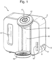
- Fig. 1 is a perspective view of an embodiment of the invention and shows an appliance 1 for dispensing warm water for the preparation of infant formula milk from powdered infant formula.
- the appliance is shown with an outer housing 2, in which is provided a window 4 for viewing the water level in the internal water tank 6 (see Figs. 2 and 3 ).
- On the right hand side of the housing 2 there are three user input buttons 8. These are used to set the timer when a new water filter has been installed, to run a cleaning cycle of the appliance 1, and to run a descaling cycle.
- a panel of LEDs 10 display various operational states of the appliance 1, i.e. a warning light to indicate that the water filter need changing.
- An on-off button 12 and rotatable dispense volume dial 13 are provided above the dispensing outlet 14, which is located above a drip tray 16.
- a baby bottle or cup 17 (shown in Fig. 5 ) can be placed on the drip tray 16 such that in use the heated water is dispensed into the bottle or cup 17, with the outer housing 2 having a vertically extending recess 18 between the drip tray 16 and the dispensing outlet 14 to accommodate the bottle 17.
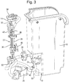
- the major internal components of the appliance 1 can be seen in the perspective views of Fig. 2 and 3 , from the front and rear of the appliance 1 respectively, in which the outer housing 2 has been removed.
- the internal water tank 6 with its window 4 is shown on the left, and has an outlet 19 towards its base which feeds a water conduit 20.
- the water conduit 20 passes first through a pump e.g. solenoid pump 22 and then past a pressure relief valve 24 and through a pressure compensating constant flow valve 26.
- the pressure relief valve 24 vents back into the water tank 6 in the event of the water conduit 20 becoming over-pressurised.
- a suitable pressure compensating constant flow valve 26 is available from Netafim ( www.netafim.com ).
- the water conduit 20 passes to a flow heater 27 in which a water flow tube 28 is brazed to a sheathed heating element 30. Cold tails 32 at either end of the sheathed heating element 30 connect it to a power supply (not shown).
- the water flow tube 28 passes to the final section of the water conduit 20 which then feeds to a dispensing head 34 and the outlet 14.
- the dispensing head 34 may take the form of an intermediate chamber receiving the liquid and/or vapour that exits from the flow heater 27. The dispensing head 34 may help to enable any steam to separate from the heated liquid so that there is a controlled flow out of the outlet 14 without any spitting.
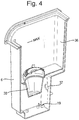
- the inside of the water tank 6 can be seen in the cross-sectional view of Fig. 4 which shows that a water hopper 36 is provided inside the top of the water tank 6. It is this water hopper 36 into which untreated water, e.g. tap water, is placed. An anti-microbial filter 38 is located at the bottom of the water hopper 36 to allow water to drain into the bottom of the water tank 6 before it exits the tank via the outlet 19. Also can be seen is the inlet 37 into the water tank 6 from the pressure relief valve 24.
- a number of temperature sensors are placed at various points around the heating system.
- a temperature sensor e.g. negative temperature coefficient thermistor 40 protrudes through the wall of the water tank 6 to sense the temperature of the filtered water in the bottom of the water tank 6.
- a second temperature sensor e.g. negative temperature coefficient thermistor 42 is placed towards the exit end and on the outside of the sheathed heating element 30.
- two bimetallic actuators e.g. half inch discs or thermal fuses 44, 46 (or other temperature sensing means) are provided on the outside of the flow heater 27, one in contact with just the water flow tube 28 and the other in contact with both the sheathed heating element 30 and the water flow tube 28.
- the two half inch discs or thermal fuses 44, 46 protect against the sheathed heating element 30 overheating.
- Such an arrangement of temperature sensing means in thermal communication with both the heating element 30 and the water flow tube 28 is also described in the Applicant's published application WO 2013/024286 .
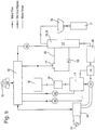
- the main components of the appliance 1 can also be seen in schematic form in Fig. 5 , in which the flow of water, electrical signals and power is also shown. All the components are directly or indirectly controlled by an electronic controller 50 which receives electronic signals from various components and controls the power delivered to the sheathed heating element 30 and the solenoid pump 22.
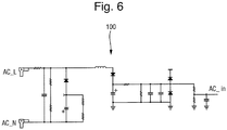
- the electronic controller 50 is connected to a mains power supply 52 via a voltage measuring circuit 100.
- the sheathed heating element 30 is also connected to the mains power supply 52, with this being controlled by the electronic controller 50 via a switch 54 in the heater power supply circuit 56.
- the pump 22 is connected to the mains power supply 52, with this being controlled by the electronic controller 50 via a pump power control 58.
- the electronic controller 50 receives electrical signals from the negative temperature coefficient thermistor 40 in the water tank 6 and the second negative temperature coefficient thermistor 42 on the sheathed heating element 30, as well as from the pump power control 58 and a water level sensor 60 (not shown in Figs. 2 and 3 ) which detects that a minimum fill level in the water tank 6 has been reached.
- the solenoid pump 22 may be replaced with another kind of pump, for example a positive displacement pump 22' such as a piston pump.
- the pressure compensating constant flow valve 26 may be omitted, especially where the pump 22' is able to deliver a substantially constant flow rate through the flow heater 27 despite variations in water pressure.
- Yet other embodiments may omit a pump altogether, relying instead on a direct connection to an external supply such as the mains water supply and using a constant flow valve or regulator to ensure that the flow rate through the heater is known.
- Fig. 6 provides an example of a suitable voltage measuring circuit 100 connected between the live AC_L and neutral AC_N poles of the mains power supply 52 for the appliance 1.
- the circuit 100 measures the analogue voltage level AC_in and provides this to an A/D converter of the electronic controller 50 to give a digital input.
- the supply voltage V_in used by the electronic controller 50 is proportional to this digital input.
- the apparatus When the apparatus starts a new dispensing cycle, it first conducts a preheating phase.
- the sheathed heating element 30 is turned on.
- the measured supply voltage V_in is used to calculate the instantaneous heating element power Q_dot according to Equation 1:
- Q _ dot V _ in ⁇ 2 / V _ cal ⁇ 2 ⁇ Q _ dot _ cal
- V_cal and Q_dot_cal are the calibrated values of the heating element voltage and heating element power as determined during an initial calibration of the appliance (either after manufacture or when the appliance is first used).
- the appliance therefore accounts for variations in the mains supply voltage 52 every time it runs a dispensing cycle. Once the supply voltage V_in has been measured it is not monitored again during the same dispensing cycle.
- the electronic controller 50 calculates the energy needed to heat a predetermined volume of liquid Vol_feed to a desired final temperature T_feed.
- the liquid volume Vol_feed may be set or selected a user via the input dial 13.
- the temperature, T_tank, of water in the tank 6 is measured by the negative temperature coefficient thermistor 40 and provided to the electronic controller 50.
- the ambient temperature for water in the tank 6 will vary depending on the ambient conditions.
- K 1 A typical value for K 1 can be empirically determined from factory testing or calibration of the apparatus, and pre-programmed into the controller.
- the first volume V_initial is dispensed at a temperature T_initialdispense > 70 °C to "sterilise" the milk powder in the bottle 17.
- T_target 210 °C
- the actual temperature, T_element, of the sheathed heating element 30 is measured by the negative temperature coefficient thermistor 42 on the sheathed heating element 30.
- Q _ preheat m ⁇ Cp ⁇ T _ target ⁇ T_element
- Cp the specific heat capacity of the heater
- m the mass of the heater
- t_ heater Q _ total ⁇ Q _ Stored / Q _ dot
- t_pump1 Vol_initial/Flow rate
- t_pump2 Vol_cold / flow rate
- the flow rate is another value that may be calibrated for each appliance (either after manufacture or when the appliance is first used).
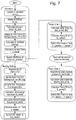
- Figure 7 is a flow chart outlining the main steps involved in a complete dispensing cycle. It can be seen that the process starts by measuring the mains supply voltage V_in at that time so as to make an accurate calculation of the power Q_dot of the sheathed heating element 30.
- the electronic controller 50 then takes readings from the negative temperature coefficient thermistor 40 (NTC1) in the water tank 6 and the second negative temperature coefficient thermistor 42 (NTC2) on the sheathed heating element 30.
- the electronic controller 50 may be programmed to pause for a set period of time, t_pause, e.g. 30 s, 40 s, 50 s or 60 s, to allow a user to add infant formula powder to the initially dispensed water, or to stir the feed if the formula powder was already in the bottle 17.
- t_pause e.g. 30 s, 40 s, 50 s or 60 s
- the appliance 1 may be provided with a button or other input allowing a user to start the second dispensing period on demand.
- the flow rate of liquid entering the flow heater 27 is set by the pressure compensating constant flow valve 26 so as to have a constant value (e.g. 170 ml/min) regardless of any variations in the pump speed e.g. due to voltage fluctuations or as a result of age-related wear. Under certain circumstances it may be necessary to reduce the flow rate to provide the desired dispense temperature and this may be achieved by pulsing the pump on and off.
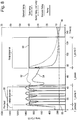
- Fig. 8 shows a plot of the operation of the sheathed heating element 30 and the pump 22 overlaid on the temperature profiles sensed for the sheathed heating element 30 i.e. T_element 52, and the outlet temperature 54 measured at the dispensing head of the appliance.
- the heater energisation state 58 and the pump operation state 60 are also shown.
- t_pump2 When the second period of pump operation, t_pump2, begins, there is a small volume of warm water dispensed through the outlet that has been sitting in the water flow tube 28, but this is quickly followed by most of the volume Vol_cold of unheated water that is pumped through during the period t_pump2.
- the outlet temperature 54 rapidly falls to match the ambient water (e.g. at 18 °C) that is being pumped through without any heating.
- the two volumes of water that are dispensed into the bottle 17 mix to provide the predetermined volume V_feed at the desired final temperature T_feed (e.g. set at 37 °C).
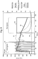
- Fig. 9 shows a temperature profile 62 for the dispensed water in the bottle throughout the operational cycle of the appliance.
- the water temperature very quickly rises to about 95°C.
- the first volume of water, V_initial has an average temperature of about 80°C and this remains above 70°C during the pause, t_pause, when the powdered infant formula is added to the bottle, ensuring sterilisation of the powder.
- T_feed T_tank + Q_dot/ m _ feed ⁇ Cp_water
- m_feed is the mass of the overall volume Vol_feed of liquid in the bottle 17.
- FIG. 10 shows the steps that may be taken when the apparatus is operated to continuously dispense a predetermined volume of warm liquid Vol_feed having a desired final temperature of T_feed e.g. 37 °C.
- the apparatus is not used to dispense a separate first volume V_initial at a particular predetermined initial temperature, i.e. no "hot shot” at 70 °C or higher.
- some of the liquid may be dispensed at such temperatures during a first phase of operation but there is no pause for a user to knowingly mix infant milk formula with the liquid while it is at this temperature.
- the heating element 30 is energised at substantially the same time as the pump 22, i.e. there is no preheating of the flow heater 27.
- a voltage compensation circuit may be used to measure the voltage V_in applied to the flow heater 27.
- the electronic controller 50 calculates the heating element power according to Eq. 1 and then calculates the predetermined volume Vol_feed from the feed size (kg) input at the user interface MMI. The total energy Q_total needed to heat the predetermined volume Vol_feed to the desired final temperature T_feed can then be calculated according to Eq. 2.
- t_pump Vol_feed/flow rate where the flow rate is that of the liquid entering the flow heater 27.
- This flow rate may be set by an upstream pressure compensating constant flow valve 26, where provided, or it may be a known constant of the pump 22'.
- T1 T_tank
- T2 T_element
- the total energy required Q_total is then calculated using Eq. 2.
- the controller 50 also calculates G_stored using Eq. 5.
- the heater ON time t_heater can then be calculated from Eq. 6.
- the pump 22, 22' may be operated continuously or the liquid may be dispensing substantially continuously using a pulsed pump operation.
- the heater ON time t_heater may be almost as long as the pump ON time t_pump, at a constant flow rate, so the controller 50 checks whether pulsed pump operation is required, e.g. if t_heater > t_pump - 3s.
- the flow heater 27 is de-energised after the time t_heater has lapsed.
- the pump is operated (continuously or in a pulsed fashion) until t_pump has lapsed and residual heat has been removed such that Vol_feed has the desired temperature T_feed.
- Figs. 11 and 12 shows the activation profiles for the heater 27 and pump 22, 22', as well as the temperature profiles for the water in the tank T_tank (measured by NTC1), the heater T_element (measured by NTC2) and the temperature of heated liquid being dispensed into a bottle at the outlet.
Landscapes
- Engineering & Computer Science (AREA)
- Food Science & Technology (AREA)
- Devices For Dispensing Beverages (AREA)
- Apparatus For Making Beverages (AREA)
- Cookers (AREA)
- External Artificial Organs (AREA)
- Control Of Positive-Displacement Pumps (AREA)
- Control Of Resistance Heating (AREA)
Applications Claiming Priority (2)
| Application Number | Priority Date | Filing Date | Title |
|---|---|---|---|
| GBGB1301297.6A GB201301297D0 (en) | 2013-01-24 | 2013-01-24 | Liquid heating apparatus |
| PCT/GB2014/050174 WO2014114935A1 (en) | 2013-01-24 | 2014-01-22 | Liquid heating apparatus and operating methods |
Publications (2)
| Publication Number | Publication Date |
|---|---|
| EP2948032A1 EP2948032A1 (en) | 2015-12-02 |
| EP2948032B1 true EP2948032B1 (en) | 2018-04-25 |
Family
ID=47843832
Family Applications (1)
| Application Number | Title | Priority Date | Filing Date |
|---|---|---|---|
| EP14701605.9A Active EP2948032B1 (en) | 2013-01-24 | 2014-01-22 | Liquid heating apparatus and operating methods |
Country Status (12)
| Country | Link |
|---|---|
| US (1) | US10226152B2 (zh) |
| EP (1) | EP2948032B1 (zh) |
| JP (1) | JP6416121B2 (zh) |
| CN (1) | CN104955366B (zh) |
| AU (1) | AU2014208971B2 (zh) |
| ES (1) | ES2670804T3 (zh) |
| GB (1) | GB201301297D0 (zh) |
| HK (1) | HK1211448A1 (zh) |
| RU (1) | RU2627212C2 (zh) |
| TR (1) | TR201807561T4 (zh) |
| WO (1) | WO2014114935A1 (zh) |
| ZA (1) | ZA201504527B (zh) |
Families Citing this family (24)
| Publication number | Priority date | Publication date | Assignee | Title |
|---|---|---|---|---|
| CN112167982A (zh) * | 2014-08-20 | 2021-01-05 | 布瑞威利私人有限公司 | 滴滤咖啡制作装置 |
| KR102293489B1 (ko) * | 2014-09-12 | 2021-08-27 | 코웨이 주식회사 | 커피 추출 장치 및 이의 히터 예열 방법 |
| US20160249766A1 (en) * | 2015-02-28 | 2016-09-01 | Briggo, Inc. | Automated beverage generating system and method of operating the same |
| DE102015113752A1 (de) * | 2015-08-19 | 2017-02-23 | Eugster/Frismag Ag | Vorrichtung zur Bereitung eines Heißgetränkes und Verwendung einer solchen |
| WO2017062979A1 (en) * | 2015-10-08 | 2017-04-13 | Flow Control Llc. | Solenoid pump mounting method |
| GB2549478A (en) * | 2016-04-18 | 2017-10-25 | Pernod Ricard | Beverage dispensing apparatus and method |
| CN106136881B (zh) * | 2016-08-10 | 2018-08-17 | 北京兆易创新科技股份有限公司 | 一种电水壶及其使用方法 |
| WO2018036653A1 (en) * | 2016-08-24 | 2018-03-01 | Innosteam Swiss Sa | Device and method to produce instant hot water |
| US20180100137A1 (en) * | 2016-10-07 | 2018-04-12 | Heateflex Corporation | Automated culture media preparation system and method for microbiology testing |
| DE102017112657A1 (de) * | 2017-06-08 | 2018-12-13 | Miele & Cie. Kg | Getränkeautomat zur Zubereitung eines Teegetränkes |
| DE102017123642A1 (de) * | 2017-10-11 | 2019-04-11 | Franke Kaffeemaschinen Ag | Vorrichtung zum erzeugen von milchschaum |
| TWI686156B (zh) * | 2018-08-24 | 2020-03-01 | 吉諾工業有限公司 | 飲料輸送裝置 |
| IT201900018401A1 (it) * | 2019-10-10 | 2021-04-10 | Simonelli Group Spa | Vaschetta di scarico per elettrovalvole di macchine per l’erogazione del caffè e macchina per l’erogazione del caffè provvista di tale vaschetta di scarico. |
| CN111035240B (zh) * | 2019-12-19 | 2021-06-29 | 珠海格力电器股份有限公司 | 一种水温定温控制方法及电热水设备 |
| CN113126522A (zh) * | 2019-12-31 | 2021-07-16 | 浙江苏泊尔家电制造有限公司 | 烹饪方法、烹饪器具和计算机存储介质 |
| IT202000016831A1 (it) * | 2020-07-10 | 2022-01-10 | G B Progetti S R L | Metodo di controllo per l’erogazione di un fluido caldo e dispositivo erogatore di un fluido caldo. |
| GB2600398B (en) * | 2020-10-21 | 2023-04-05 | Otter Controls Ltd | Liquid heating and dispensing apparatus and method |
| CN112361608A (zh) * | 2020-10-27 | 2021-02-12 | 安徽佳暖节能科技有限公司 | 一种智能超高频电热水器的控制方法 |
| CN116419698A (zh) * | 2020-10-28 | 2023-07-11 | 库里格绿山股份有限公司 | 用于饮料机的两用温度和导电探针 |
| US11542148B2 (en) * | 2021-03-10 | 2023-01-03 | Haier Us Appliance Solutions, Inc. | Free-standing beverage dispensing appliance and method for operating a beverage dispensing appliance |
| CN117320597A (zh) * | 2021-05-26 | 2023-12-29 | 菲仕兰坎皮纳荷兰公司 | 用于分配热的含奶饮料组分或饮料的一部分的系统和方法、以及厚膜加热器的用途 |
| CN114403710A (zh) * | 2021-12-08 | 2022-04-29 | 广东水护盾健康科技有限公司 | 液体加热设备的操作方法 |
| CN114224167A (zh) * | 2021-12-09 | 2022-03-25 | 广东水护盾健康科技有限公司 | 液体加热设备的控制方法 |
| CN114747943B (zh) * | 2022-04-29 | 2024-03-15 | 佛山市顺德区美的饮水机制造有限公司 | 即热饮水机及其预热控制方法与装置、存储介质 |
Family Cites Families (39)
| Publication number | Priority date | Publication date | Assignee | Title |
|---|---|---|---|---|
| ATE146054T1 (de) | 1992-07-01 | 1996-12-15 | Sintra Holding Ag | Gerät zum zubereiten von heissen getränken |
| US6118933A (en) * | 1992-11-25 | 2000-09-12 | Roberson; Danny J. | Apparatus and method for preparing infant formula from powder with dispensing and filtering means |
| US5671325A (en) * | 1992-11-25 | 1997-09-23 | Roberson; Danny J. | Apparatus for preparing infant formula from powder |
| US5397031A (en) | 1994-03-08 | 1995-03-14 | Jensen; Martin T. | Baby milk warmer |
| RU2136097C1 (ru) | 1998-03-17 | 1999-08-27 | Волошин Аркадий Иосифович | Устройство для защиты потребителя от повышенного и пониженного напряжения в сети переменного тока |
| AU6441500A (en) | 1999-09-10 | 2001-04-17 | Lutz Thomssen | Device for tempering orally administered, liquid or pasty media, method for operating the device and use thereof |
| KR20010037405A (ko) | 1999-10-16 | 2001-05-07 | 구자홍 | 히터 구동전력 보정방법 |
| JP2003325329A (ja) | 2002-05-14 | 2003-11-18 | Matsushita Electric Ind Co Ltd | 炊飯器 |
| EP1462043B1 (de) * | 2003-03-24 | 2006-03-01 | Wmf Württembergische Metallwarenfabrik Ag | Verfahren zum Steuern einer Getränkezubereitungsmaschine |
| AU2003279525A1 (en) | 2003-10-06 | 2005-04-21 | Fabrizia Di Giampaolo | Device for producing a sterilisable heated emulsion of milk and air |
| PL1763312T3 (pl) | 2004-06-14 | 2008-09-30 | Mathias Och | Urządzenie do przygotowywania pokarmu dla małych dzieci |
| EP1634520A1 (fr) * | 2004-09-13 | 2006-03-15 | Nestec S.A. | Dispositif de chauffage d'un liquide et procede pour chauffer un liquide |
| US7401545B2 (en) | 2004-11-09 | 2008-07-22 | Nestec S.A. | Method and apparatus for optimizing variable liquid temperatures |
| EP1748547A1 (en) | 2005-07-27 | 2007-01-31 | Rhea Vendors S.p.A. | Apparatus and process for controlling and regulating electric motor actuated devices |
| MX2008014680A (es) | 2006-05-19 | 2008-11-28 | Koninkl Philips Electronics Nv | Aparato para preparacion de bebida a partir de agua esterilizada y producto instantaneo. |
| ATE470385T1 (de) | 2006-05-19 | 2010-06-15 | Koninkl Philips Electronics Nv | Vorrichtung zur zubereitung eines getränks aus sterilisiertem wasser mit einer vorbestimmten verzehrtemperatur |
| DE102006062352A1 (de) | 2006-12-22 | 2008-06-26 | Alfred Kärcher Gmbh & Co. Kg | Wasserabgabegerät und Getränkeabgabevorrichtung mit einem Wasserabgabegerät |
| US7863546B2 (en) * | 2006-12-27 | 2011-01-04 | Kraft Foods Global Brands Llc | Automated preparation of infant formula and children's beverages |
| JP2010519688A (ja) * | 2007-02-16 | 2010-06-03 | コーニンクレッカ フィリップス エレクトロニクス エヌ ヴィ | 液体フロースルーヒーターの制御 |
| KR100827383B1 (ko) | 2007-03-23 | 2008-05-06 | 웅진코웨이주식회사 | 전압 제어가 가능한 히터 |
| CN101657130B (zh) * | 2007-04-16 | 2013-12-11 | 皇家飞利浦电子股份有限公司 | 用于产生饮料的装置和该装置的用途 |
| JP5030177B2 (ja) | 2007-11-05 | 2012-09-19 | 日本特殊陶業株式会社 | ガスセンサ制御装置およびガスセンサ制御システム |
| CN201177768Y (zh) | 2007-12-19 | 2009-01-07 | 白勇 | 电热水器用恒温控制装置 |
| ITMI20072446A1 (it) | 2007-12-28 | 2009-06-29 | Tenacta Group Spa | "macchina per caffe' espresso dotata di controllo migliorato della pompa e metodo di controllo" |
| CN201165611Y (zh) | 2008-03-25 | 2008-12-17 | 广东广雅中学 | 具有停电恢复功能的洗衣机 |
| DE102008056412A1 (de) | 2008-11-07 | 2010-05-12 | BSH Bosch und Siemens Hausgeräte GmbH | Haushaltsgerät mit einer Luft-Trocknungsvorrichtung und/oder Flüssigkeits-Heizungseinrichtung sowie zugehöriges Verfahren |
| KR20120085656A (ko) * | 2009-05-20 | 2012-08-01 | 스트릭스 리미티드 | 가열기 |
| WO2010106348A2 (en) | 2009-05-20 | 2010-09-23 | Strix Limited | Heaters |
| GB201001040D0 (en) | 2010-01-22 | 2010-03-10 | Strix Ltd | Liquid heating apparatus |
| KR101118850B1 (ko) | 2009-06-24 | 2012-03-07 | 강미선 | 분유디스펜서 |
| KR101084175B1 (ko) | 2009-11-23 | 2011-11-17 | 삼성모바일디스플레이주식회사 | 유기 발광 디스플레이 장치 및 그 제조 방법 |
| AU2010334628B2 (en) * | 2009-12-21 | 2015-07-09 | Strix Limited | Flow heaters |
| WO2011157675A1 (en) * | 2010-06-17 | 2011-12-22 | Nestec S.A. | Fast heat-up of a thermal conditioning device e.g. for coffee machine |
| FR2961649B1 (fr) | 2010-06-18 | 2012-07-27 | Schneider Electric Ind Sas | Procede et systeme de communication bases sur ws-discovery |
| JP2012061127A (ja) * | 2010-09-16 | 2012-03-29 | Marin Trading Co | 湯沸かし装置 |
| EP2661202A2 (en) | 2011-01-06 | 2013-11-13 | Strix Limited | Liquid heating apparatus |
| GB201102971D0 (en) * | 2011-02-21 | 2011-04-06 | Strix Ltd | Electrical water heating appliances |
| GB2493719A (en) | 2011-08-15 | 2013-02-20 | Strix Ltd | Flow heater with temperature sensing and a heat sink |
| WO2013100486A1 (en) | 2011-12-30 | 2013-07-04 | Coway Co., Ltd. | Hot water supply apparatus and hot water supply method |
-
2013
- 2013-01-24 GB GBGB1301297.6A patent/GB201301297D0/en not_active Ceased
-
2014
- 2014-01-22 JP JP2015554246A patent/JP6416121B2/ja active Active
- 2014-01-22 RU RU2015132171A patent/RU2627212C2/ru active
- 2014-01-22 CN CN201480006057.0A patent/CN104955366B/zh active Active
- 2014-01-22 WO PCT/GB2014/050174 patent/WO2014114935A1/en active Application Filing
- 2014-01-22 US US14/763,433 patent/US10226152B2/en active Active
- 2014-01-22 EP EP14701605.9A patent/EP2948032B1/en active Active
- 2014-01-22 ES ES14701605.9T patent/ES2670804T3/es active Active
- 2014-01-22 AU AU2014208971A patent/AU2014208971B2/en active Active
- 2014-01-22 TR TR2018/07561T patent/TR201807561T4/tr unknown
-
2015
- 2015-06-23 ZA ZA2015/04527A patent/ZA201504527B/en unknown
- 2015-12-14 HK HK15112272.7A patent/HK1211448A1/zh unknown
Non-Patent Citations (1)
| Title |
|---|
| None * |
Also Published As
| Publication number | Publication date |
|---|---|
| US20160045062A1 (en) | 2016-02-18 |
| AU2014208971A1 (en) | 2015-07-09 |
| RU2015132171A (ru) | 2017-03-02 |
| HK1211448A1 (zh) | 2016-05-27 |
| JP6416121B2 (ja) | 2018-10-31 |
| WO2014114935A1 (en) | 2014-07-31 |
| ES2670804T3 (es) | 2018-06-01 |
| JP2016504139A (ja) | 2016-02-12 |
| ZA201504527B (en) | 2017-11-29 |
| CN104955366A (zh) | 2015-09-30 |
| CN104955366B (zh) | 2018-04-27 |
| EP2948032A1 (en) | 2015-12-02 |
| AU2014208971B2 (en) | 2018-10-11 |
| RU2627212C2 (ru) | 2017-08-03 |
| GB201301297D0 (en) | 2013-03-06 |
| US10226152B2 (en) | 2019-03-12 |
| TR201807561T4 (tr) | 2018-06-21 |
Similar Documents
| Publication | Publication Date | Title |
|---|---|---|
| EP2948032B1 (en) | Liquid heating apparatus and operating methods | |
| US8127662B2 (en) | Apparatus for preparing a beverage from sterilized water of a predetermined consumption temperature | |
| ES2466017T3 (es) | Calentamiento rápido de un dispositivo de acondicionamiento térmico, por ejemplo, para máquina de café | |
| US10368689B2 (en) | Advanced heating device | |
| EP2709500B1 (en) | Apparatus and method for an improved coffee maker | |
| KR102455975B1 (ko) | 추출 시스템 및 음료 추출 프로세스 | |
| JP7343497B2 (ja) | 飲料を調製するための装置及び方法 | |
| WO2019069097A2 (en) | LIQUID HEATING APPARATUS AND CIRCULATING WATER HEATER | |
| GB2571788A (en) | Method and apparatus for dispensing sterilised and cooled water | |
| EP2471421B1 (en) | Method and machine for producing beverages from soluble material | |
| JP2024520038A (ja) | 温かいミルク含有飲料成分又は飲料の部分を分配するためのシステム及び方法、並びに厚膜ヒータの使用 | |
| GB2567213A (en) | Liquid heating appliances and flow heaters |
Legal Events
| Date | Code | Title | Description |
|---|---|---|---|
| PUAI | Public reference made under article 153(3) epc to a published international application that has entered the european phase |
Free format text: ORIGINAL CODE: 0009012 |
|
| 17P | Request for examination filed |
Effective date: 20150728 |
|
| AK | Designated contracting states |
Kind code of ref document: A1 Designated state(s): AL AT BE BG CH CY CZ DE DK EE ES FI FR GB GR HR HU IE IS IT LI LT LU LV MC MK MT NL NO PL PT RO RS SE SI SK SM TR |
|
| AX | Request for extension of the european patent |
Extension state: BA ME |
|
| DAX | Request for extension of the european patent (deleted) | ||
| GRAP | Despatch of communication of intention to grant a patent |
Free format text: ORIGINAL CODE: EPIDOSNIGR1 |
|
| STAA | Information on the status of an ep patent application or granted ep patent |
Free format text: STATUS: GRANT OF PATENT IS INTENDED |
|
| INTG | Intention to grant announced |
Effective date: 20170512 |
|
| GRAJ | Information related to disapproval of communication of intention to grant by the applicant or resumption of examination proceedings by the epo deleted |
Free format text: ORIGINAL CODE: EPIDOSDIGR1 |
|
| STAA | Information on the status of an ep patent application or granted ep patent |
Free format text: STATUS: REQUEST FOR EXAMINATION WAS MADE |
|
| INTC | Intention to grant announced (deleted) | ||
| GRAJ | Information related to disapproval of communication of intention to grant by the applicant or resumption of examination proceedings by the epo deleted |
Free format text: ORIGINAL CODE: EPIDOSDIGR1 |
|
| GRAL | Information related to payment of fee for publishing/printing deleted |
Free format text: ORIGINAL CODE: EPIDOSDIGR3 |
|
| GRAP | Despatch of communication of intention to grant a patent |
Free format text: ORIGINAL CODE: EPIDOSNIGR1 |
|
| GRAS | Grant fee paid |
Free format text: ORIGINAL CODE: EPIDOSNIGR3 |
|
| GRAJ | Information related to disapproval of communication of intention to grant by the applicant or resumption of examination proceedings by the epo deleted |
Free format text: ORIGINAL CODE: EPIDOSDIGR1 |
|
| GRAP | Despatch of communication of intention to grant a patent |
Free format text: ORIGINAL CODE: EPIDOSNIGR1 |
|
| GRAS | Grant fee paid |
Free format text: ORIGINAL CODE: EPIDOSNIGR3 |
|
| GRAR | Information related to intention to grant a patent recorded |
Free format text: ORIGINAL CODE: EPIDOSNIGR71 |
|
| GRAS | Grant fee paid |
Free format text: ORIGINAL CODE: EPIDOSNIGR3 |
|
| STAA | Information on the status of an ep patent application or granted ep patent |
Free format text: STATUS: GRANT OF PATENT IS INTENDED |
|
| GRAA | (expected) grant |
Free format text: ORIGINAL CODE: 0009210 |
|
| STAA | Information on the status of an ep patent application or granted ep patent |
Free format text: STATUS: THE PATENT HAS BEEN GRANTED |
|
| INTG | Intention to grant announced |
Effective date: 20180314 |
|
| AK | Designated contracting states |
Kind code of ref document: B1 Designated state(s): AL AT BE BG CH CY CZ DE DK EE ES FI FR GB GR HR HU IE IS IT LI LT LU LV MC MK MT NL NO PL PT RO RS SE SI SK SM TR |
|
| REG | Reference to a national code |
Ref country code: GB Ref legal event code: FG4D |
|
| REG | Reference to a national code |
Ref country code: CH Ref legal event code: EP |
|
| REG | Reference to a national code |
Ref country code: AT Ref legal event code: REF Ref document number: 991938 Country of ref document: AT Kind code of ref document: T Effective date: 20180515 |
|
| REG | Reference to a national code |
Ref country code: IE Ref legal event code: FG4D |
|
| REG | Reference to a national code |
Ref country code: DE Ref legal event code: R096 Ref document number: 602014024379 Country of ref document: DE |
|
| REG | Reference to a national code |
Ref country code: ES Ref legal event code: FG2A Ref document number: 2670804 Country of ref document: ES Kind code of ref document: T3 Effective date: 20180601 |
|
| REG | Reference to a national code |
Ref country code: SE Ref legal event code: TRGR |
|
| REG | Reference to a national code |
Ref country code: NL Ref legal event code: FP |
|
| REG | Reference to a national code |
Ref country code: LT Ref legal event code: MG4D |
|
| PG25 | Lapsed in a contracting state [announced via postgrant information from national office to epo] |
Ref country code: NO Free format text: LAPSE BECAUSE OF FAILURE TO SUBMIT A TRANSLATION OF THE DESCRIPTION OR TO PAY THE FEE WITHIN THE PRESCRIBED TIME-LIMIT Effective date: 20180725 Ref country code: PL Free format text: LAPSE BECAUSE OF FAILURE TO SUBMIT A TRANSLATION OF THE DESCRIPTION OR TO PAY THE FEE WITHIN THE PRESCRIBED TIME-LIMIT Effective date: 20180425 Ref country code: BG Free format text: LAPSE BECAUSE OF FAILURE TO SUBMIT A TRANSLATION OF THE DESCRIPTION OR TO PAY THE FEE WITHIN THE PRESCRIBED TIME-LIMIT Effective date: 20180725 Ref country code: FI Free format text: LAPSE BECAUSE OF FAILURE TO SUBMIT A TRANSLATION OF THE DESCRIPTION OR TO PAY THE FEE WITHIN THE PRESCRIBED TIME-LIMIT Effective date: 20180425 Ref country code: LT Free format text: LAPSE BECAUSE OF FAILURE TO SUBMIT A TRANSLATION OF THE DESCRIPTION OR TO PAY THE FEE WITHIN THE PRESCRIBED TIME-LIMIT Effective date: 20180425 |
|
| PG25 | Lapsed in a contracting state [announced via postgrant information from national office to epo] |
Ref country code: LV Free format text: LAPSE BECAUSE OF FAILURE TO SUBMIT A TRANSLATION OF THE DESCRIPTION OR TO PAY THE FEE WITHIN THE PRESCRIBED TIME-LIMIT Effective date: 20180425 Ref country code: HR Free format text: LAPSE BECAUSE OF FAILURE TO SUBMIT A TRANSLATION OF THE DESCRIPTION OR TO PAY THE FEE WITHIN THE PRESCRIBED TIME-LIMIT Effective date: 20180425 Ref country code: GR Free format text: LAPSE BECAUSE OF FAILURE TO SUBMIT A TRANSLATION OF THE DESCRIPTION OR TO PAY THE FEE WITHIN THE PRESCRIBED TIME-LIMIT Effective date: 20180726 Ref country code: RS Free format text: LAPSE BECAUSE OF FAILURE TO SUBMIT A TRANSLATION OF THE DESCRIPTION OR TO PAY THE FEE WITHIN THE PRESCRIBED TIME-LIMIT Effective date: 20180425 |
|
| REG | Reference to a national code |
Ref country code: AT Ref legal event code: MK05 Ref document number: 991938 Country of ref document: AT Kind code of ref document: T Effective date: 20180425 |
|
| PG25 | Lapsed in a contracting state [announced via postgrant information from national office to epo] |
Ref country code: PT Free format text: LAPSE BECAUSE OF FAILURE TO SUBMIT A TRANSLATION OF THE DESCRIPTION OR TO PAY THE FEE WITHIN THE PRESCRIBED TIME-LIMIT Effective date: 20180827 |
|
| REG | Reference to a national code |
Ref country code: DE Ref legal event code: R097 Ref document number: 602014024379 Country of ref document: DE |
|
| PG25 | Lapsed in a contracting state [announced via postgrant information from national office to epo] |
Ref country code: DK Free format text: LAPSE BECAUSE OF FAILURE TO SUBMIT A TRANSLATION OF THE DESCRIPTION OR TO PAY THE FEE WITHIN THE PRESCRIBED TIME-LIMIT Effective date: 20180425 Ref country code: AT Free format text: LAPSE BECAUSE OF FAILURE TO SUBMIT A TRANSLATION OF THE DESCRIPTION OR TO PAY THE FEE WITHIN THE PRESCRIBED TIME-LIMIT Effective date: 20180425 Ref country code: EE Free format text: LAPSE BECAUSE OF FAILURE TO SUBMIT A TRANSLATION OF THE DESCRIPTION OR TO PAY THE FEE WITHIN THE PRESCRIBED TIME-LIMIT Effective date: 20180425 Ref country code: CZ Free format text: LAPSE BECAUSE OF FAILURE TO SUBMIT A TRANSLATION OF THE DESCRIPTION OR TO PAY THE FEE WITHIN THE PRESCRIBED TIME-LIMIT Effective date: 20180425 Ref country code: RO Free format text: LAPSE BECAUSE OF FAILURE TO SUBMIT A TRANSLATION OF THE DESCRIPTION OR TO PAY THE FEE WITHIN THE PRESCRIBED TIME-LIMIT Effective date: 20180425 Ref country code: SK Free format text: LAPSE BECAUSE OF FAILURE TO SUBMIT A TRANSLATION OF THE DESCRIPTION OR TO PAY THE FEE WITHIN THE PRESCRIBED TIME-LIMIT Effective date: 20180425 |
|
| PG25 | Lapsed in a contracting state [announced via postgrant information from national office to epo] |
Ref country code: SM Free format text: LAPSE BECAUSE OF FAILURE TO SUBMIT A TRANSLATION OF THE DESCRIPTION OR TO PAY THE FEE WITHIN THE PRESCRIBED TIME-LIMIT Effective date: 20180425 |
|
| PLBE | No opposition filed within time limit |
Free format text: ORIGINAL CODE: 0009261 |
|
| STAA | Information on the status of an ep patent application or granted ep patent |
Free format text: STATUS: NO OPPOSITION FILED WITHIN TIME LIMIT |
|
| 26N | No opposition filed |
Effective date: 20190128 |
|
| PG25 | Lapsed in a contracting state [announced via postgrant information from national office to epo] |
Ref country code: SI Free format text: LAPSE BECAUSE OF FAILURE TO SUBMIT A TRANSLATION OF THE DESCRIPTION OR TO PAY THE FEE WITHIN THE PRESCRIBED TIME-LIMIT Effective date: 20180425 |
|
| PG25 | Lapsed in a contracting state [announced via postgrant information from national office to epo] |
Ref country code: MC Free format text: LAPSE BECAUSE OF FAILURE TO SUBMIT A TRANSLATION OF THE DESCRIPTION OR TO PAY THE FEE WITHIN THE PRESCRIBED TIME-LIMIT Effective date: 20180425 |
|
| REG | Reference to a national code |
Ref country code: CH Ref legal event code: PL |
|
| PG25 | Lapsed in a contracting state [announced via postgrant information from national office to epo] |
Ref country code: LU Free format text: LAPSE BECAUSE OF NON-PAYMENT OF DUE FEES Effective date: 20190122 |
|
| PG25 | Lapsed in a contracting state [announced via postgrant information from national office to epo] |
Ref country code: AL Free format text: LAPSE BECAUSE OF FAILURE TO SUBMIT A TRANSLATION OF THE DESCRIPTION OR TO PAY THE FEE WITHIN THE PRESCRIBED TIME-LIMIT Effective date: 20180425 |
|
| PG25 | Lapsed in a contracting state [announced via postgrant information from national office to epo] |
Ref country code: CH Free format text: LAPSE BECAUSE OF NON-PAYMENT OF DUE FEES Effective date: 20190131 Ref country code: LI Free format text: LAPSE BECAUSE OF NON-PAYMENT OF DUE FEES Effective date: 20190131 |
|
| PG25 | Lapsed in a contracting state [announced via postgrant information from national office to epo] |
Ref country code: MT Free format text: LAPSE BECAUSE OF NON-PAYMENT OF DUE FEES Effective date: 20190122 |
|
| PG25 | Lapsed in a contracting state [announced via postgrant information from national office to epo] |
Ref country code: CY Free format text: LAPSE BECAUSE OF FAILURE TO SUBMIT A TRANSLATION OF THE DESCRIPTION OR TO PAY THE FEE WITHIN THE PRESCRIBED TIME-LIMIT Effective date: 20180425 |
|
| PG25 | Lapsed in a contracting state [announced via postgrant information from national office to epo] |
Ref country code: IS Free format text: LAPSE BECAUSE OF FAILURE TO SUBMIT A TRANSLATION OF THE DESCRIPTION OR TO PAY THE FEE WITHIN THE PRESCRIBED TIME-LIMIT Effective date: 20180825 |
|
| PG25 | Lapsed in a contracting state [announced via postgrant information from national office to epo] |
Ref country code: HU Free format text: LAPSE BECAUSE OF FAILURE TO SUBMIT A TRANSLATION OF THE DESCRIPTION OR TO PAY THE FEE WITHIN THE PRESCRIBED TIME-LIMIT; INVALID AB INITIO Effective date: 20140122 |
|
| PG25 | Lapsed in a contracting state [announced via postgrant information from national office to epo] |
Ref country code: MK Free format text: LAPSE BECAUSE OF FAILURE TO SUBMIT A TRANSLATION OF THE DESCRIPTION OR TO PAY THE FEE WITHIN THE PRESCRIBED TIME-LIMIT Effective date: 20180425 |
|
| PGFP | Annual fee paid to national office [announced via postgrant information from national office to epo] |
Ref country code: FR Payment date: 20230118 Year of fee payment: 10 |
|
| PGFP | Annual fee paid to national office [announced via postgrant information from national office to epo] |
Ref country code: TR Payment date: 20230110 Year of fee payment: 10 Ref country code: SE Payment date: 20230120 Year of fee payment: 10 Ref country code: IT Payment date: 20230119 Year of fee payment: 10 Ref country code: BE Payment date: 20230117 Year of fee payment: 10 |
|
| P01 | Opt-out of the competence of the unified patent court (upc) registered |
Effective date: 20230525 |
|
| PGFP | Annual fee paid to national office [announced via postgrant information from national office to epo] |
Ref country code: NL Payment date: 20240118 Year of fee payment: 11 |
|
| PGFP | Annual fee paid to national office [announced via postgrant information from national office to epo] |
Ref country code: IE Payment date: 20240118 Year of fee payment: 11 Ref country code: ES Payment date: 20240208 Year of fee payment: 11 |
|
| PGFP | Annual fee paid to national office [announced via postgrant information from national office to epo] |
Ref country code: DE Payment date: 20240123 Year of fee payment: 11 Ref country code: GB Payment date: 20240118 Year of fee payment: 11 |