EP2947240A1 - Schloss - Google Patents
Schloss Download PDFInfo
- Publication number
- EP2947240A1 EP2947240A1 EP15168006.3A EP15168006A EP2947240A1 EP 2947240 A1 EP2947240 A1 EP 2947240A1 EP 15168006 A EP15168006 A EP 15168006A EP 2947240 A1 EP2947240 A1 EP 2947240A1
- Authority
- EP
- European Patent Office
- Prior art keywords
- latch
- bolt
- case
- stop
- biased
- Prior art date
- Legal status (The legal status is an assumption and is not a legal conclusion. Google has not performed a legal analysis and makes no representation as to the accuracy of the status listed.)
- Granted
Links
- 230000008878 coupling Effects 0.000 claims description 3
- 238000010168 coupling process Methods 0.000 claims description 3
- 238000005859 coupling reaction Methods 0.000 claims description 3
- 244000208734 Pisonia aculeata Species 0.000 claims 1
- 238000010276 construction Methods 0.000 description 3
- 230000000903 blocking effect Effects 0.000 description 2
- 230000002349 favourable effect Effects 0.000 description 2
Images


Classifications
-
- E—FIXED CONSTRUCTIONS
- E05—LOCKS; KEYS; WINDOW OR DOOR FITTINGS; SAFES
- E05B—LOCKS; ACCESSORIES THEREFOR; HANDCUFFS
- E05B63/00—Locks or fastenings with special structural characteristics
- E05B63/18—Locks or fastenings with special structural characteristics with arrangements independent of the locking mechanism for retaining the bolt or latch in the retracted position
- E05B63/20—Locks or fastenings with special structural characteristics with arrangements independent of the locking mechanism for retaining the bolt or latch in the retracted position released automatically when the wing is closed
-
- E—FIXED CONSTRUCTIONS
- E05—LOCKS; KEYS; WINDOW OR DOOR FITTINGS; SAFES
- E05B—LOCKS; ACCESSORIES THEREFOR; HANDCUFFS
- E05B15/00—Other details of locks; Parts for engagement by bolts of fastening devices
- E05B15/10—Bolts of locks or night latches
- E05B15/102—Bolts having movable elements
-
- E—FIXED CONSTRUCTIONS
- E05—LOCKS; KEYS; WINDOW OR DOOR FITTINGS; SAFES
- E05B—LOCKS; ACCESSORIES THEREFOR; HANDCUFFS
- E05B15/00—Other details of locks; Parts for engagement by bolts of fastening devices
- E05B15/04—Spring arrangements in locks
- E05B2015/0448—Units of springs; Two or more springs working together
Definitions
- the invention relates to a lock according to the preamble of claim 1.
- the aim of the invention is to avoid this disadvantage and to propose a lock of the type mentioned, in which only relatively small forces for retracting the latch and the bolt are required, however, a secure engagement of the trigger element is ensured.
- the lock should be as simple as possible, whereby the production costs are kept low.
- the features of claim 3 provide a particularly favorable construction of the trigger and the features of claim 4 provide a particularly favorable construction of the supported stop, which is ensured in a very simple manner, a secure blocking of the prestressed bolt in its retracted position with respect to the case.
- a push rod 2 is slidably supported, which is actuated by means of a pusher or a lock cylinder. This cooperates with a pivotally held in the housing 1 retraction lever 3, said parts in Fig. 1 are shown in their retracted case 4 corresponding position.
- an arm of the retraction lever 3 engages a projection 9 of a bolt 5, which is held displaceably in the case 4.
- the case 4 further has a trigger 20 which protrudes laterally on the contact surface cooperating with a striking plate from the attraction surface and when closing a door with a lock according to the invention first impinges on a strike plate and is pressed by this in the case.
- This trigger 20 is pivotable about a perpendicular to the direction of movement of the case 4 held in this axis 22 and is designed as a two-armed lever.
- the trigger 20 is biased in its rest position with protruding from the attraction surface first lever arm by a spring.
- the bolt further comprises a pin 10 which engages in a bore of a leaf spring 11 which lies in a recess of the bolt 5 and the Retracting the bolt 5 to take the case 4 by the bolt 5 is used.
- the Ausschiebeweg the trap 4 is limited in the usual way by a biased by a spring 12 against its working position slide 13, which cooperates with a stop surface of the trap, the e.g. is formed by the end of a groove arranged at the top of the case.
- a stop having a small spring travel 14 is held, which projects into the path of movement of the case 4.
- This supported by a spring 15 on the housing 1 stop 14 ensures that upon retraction of the bolt 5, the correct mutual position of the case 4 and 5 bar on reaching the retracted end position of the bolt 5 results and the trigger 20 with the free end of its lever arm 7 can be urged into a bolt 5 blocking position.
- the stop 14 protrudes with a projection 16 in the path of movement of the case 4 and in the housing 1 guide ribs 17 are arranged for the stop 14, which, as shown in Fig. 4 can be seen, two grooves 18, in which the guide ribs 17 engage.
- the leaf spring 11, which lies in a recess of the bolt 5, has a raised edge 19.
- the upstand 19 engages behind an opposite edge 21 of the case 4. By the upstand 19 of the leaf spring 11 and the edge 21, the case 4 is taken when retracting the bolt on the leaf spring 11 ( Fig. 1 ).
- the trap can be moved only after overcoming the additional force of the spring 15 of the stop 14 in the rearmost end position ( Fig. 1 ). This ensures that a possible frictional connection between latch 5 and case 4 is not sufficient to cause further entrainment of the case 4, whereby a correct mutual position of the latch 4 and the latch 5 is achieved and the lever arm 7 of the trigger 20 to rest against the Tab 8 of the bolt 5 comes.
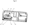
- the Fig. 5 shows for clarity a blank lock housing 1, in which only the slider 13, which is the outer end stop of the case, as well as the stop 14 are inserted.
- the stop 16 is slidably mounted on two guide ribs 17, wherein the movement path is limited by end stops in the housing 1. Since the stop 14 comes only about 2-3 mm before the rear end of the path of movement of the case 4 with its projection 16 at this plant, the force of the spring 15 acts only from this time in addition to the force of the Ausschubfeder 6, creating only more slight increase in torque takes place on the lock cylinder or pusher.
Landscapes
- Engineering & Computer Science (AREA)
- Structural Engineering (AREA)
- Lock And Its Accessories (AREA)
Abstract
Description
- Die Erfindung bezieht sich auf ein Schloss gemäß dem Oberbegriff des Anspruches 1.
- Bei solchen Schlössern, wie sie z.B. aus der
DE 102004037915 A bekannt sind, ist der Riegel in seiner zurückgezogenen Stellung durch ein Auslöseelement gegenüber der Falle blockiert. Beim Schließen einer Tür löst das Auslöseelement den Riegel aus und dieser kann über den Bewegungsweg der Falle hinausgeschoben werden und das Schloss wird dadurch automatisch verriegelt. Beim Zurückziehen des Riegels und der Falle müssen beide Teile zueinander einen ausreichenden Abstand haben, damit das Auslöseelement den Riegel wieder in zurückgezogener Stellung verrasten kann. In der Praxis ergibt sich das Problem, dass beim gemeinsamen Rückziehen von Riegel und Falle dieser notwendige Abstand nicht selbständig immer erreicht wird, wodurch das Schloss in der entsperrten Stellung nicht sicher blockiert werden würde. Um dies zu vermeiden, wurde in der oben genannten bekannten Lösung eine zweite Feder vorgesehen, welche auf die Falle einwirkt und beim Zurückziehen des Riegels die Falle in Richtung ausgeschobener Stellung zurückdrückt, damit der definierte Abstand zwischen Falle und Riegel erreicht wird. Dadurch ergibt sich jedoch der Nachteil, dass relativ hohe Kräfte zur Betätigung des Schlosses, bzw. zum Zurückziehen der Falle und des Riegels erforderlich sind, da ja Falle und Riegel gegen die jeweiligen Federn betätigt werden müssen und damit über den gesamten - Rückzugsweg das Drehmoment am Schließzylinder bzw. Drücker ansteigt.
- Ziel der Erfindung ist es, diesen Nachteil zu vermeiden und ein Schloss der eingangs erwähnten Art vorzuschlagen, bei dem nur relativ geringe Kräfte zum Zurückziehen der Falle und des Riegels erforderlich sind, jedoch ein sicheres Einrasten des Auslöseelements gewährleistet wird. Gleichzeitig sollte das Schloss möglichst einfach aufgebaut sein, wodurch die Produktionskosten gering gehalten werden.
- Erfindungsgemäß wird dies bei einem Schloss der eingangs erwähnten Art durch die kennzeichnenden Merkmale des Anspruches 1 erreicht.
- Da bei dem erfindungsgemäßen Schloss nur eine gemeinsame Feder zur Vorspannung des Riegels und der Falle vorgesehen ist, sind die erforderlichen Rückstellkräfte zum Zurückziehen der Falle und des Riegels deutlich geringer. Um sicherzustellen, dass sich beim Zurückziehen des Riegels der korrekte Abstand zwischen den in Ausschubrichtung gesehenen hinteren Endflächen der Falle und des Riegels ergibt, wirkt erst im letzten Abschnitt, im Wesentlichen auf den letzten 2-3 mm des Rückzugswegs, ein gefederter Anschlag auf die Falle ein. Auf diese Weise wird erreicht, dass, sollte die Falle durch Reibung und nicht erst durch das Mitnehmerkoppelglied beim Zurückziehen des Riegels mitgenommen werden, durch den federnden Anschlag die korrekte gegenseitige Lage von Falle und Riegel sichergestellt wird. Dabei ergeben sich erst im letzten Abschnitt des Rückzugsweges der Falle und des Riegels eine zusätzlich zu überwindende Kraft durch die Feder des Anschlags und damit ein Anstieg des Drehmoments. Dieser Anstieg ist aber aufgrund des sehr kurzen Abschnitts deutlich geringer als beim Stand der Technik, wo dieser Anstieg über den gesamten Rückzugsweg zunimmt.
- Weiters können die Merkmale des Anspruches 2 vorgesehen sein. Durch diese Maßnahmen ergibt sich eine sehr einfache Konstruktion für das Koppelglied.
- Die Merkmale des Anspruches 3 ergeben eine besonders günstige Konstruktion des Auslösers und die Merkmale des Anspruches 4 ergeben eine besonders günstige Konstruktion des abgestützten Anschlags, wodurch auf sehr einfache Weise eine sichere Blockierung des vorgespannten Riegels in seiner in Bezug auf die Falle zurückgezogenen Stellung gewährleistet ist.
- Die Erfindung wird nun anhand der Zeichnung näher erläutert. Dabei zeigen:
-
Fig. 1 schematisch ein erfindungsgemäßes Schloss mit abgehobenem Gehäusedeckel und zurückgezogener Falle, -
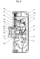
Fig. 2 eine Ansicht des Schlosses nach derFig. 1 mit ausgeschobener Falle und zurückgezogenem Riegel, -
Fig. 3 eine Teilansicht des Schlosses nachFig. 1 und2 mit ausgeschobener Falle und ausgeschobenem Riegel, -
Fig. 4 einen Anschlag für die Falle im Detail und -
Fig. 5 eine Ansicht des Gehäuses des Schlosses nur mit angeordnetem Anschlag. - In einem Gehäuse 1 ist eine Schubstange 2 verschiebbar gehalten, die mittels eines Drückers oder eines Schließzylinders betätigbar ist. Diese wirkt mit einem im Gehäuse 1 schwenkbar gehaltenen Rückzugshebel 3 zusammen, wobei diese Teile in
Fig. 1 in ihren der zurückgezogenen Falle 4 entsprechenden Stellung dargestellt sind. Dabei greift ein Arm des Rückzugshebels 3 an einem Ansatz 9 eines Riegels 5 an, der in der Falle 4 verschiebbar gehalten ist. - In der Falle 4 ist ein in Bewegungsrichtung der Falle 4 verschiebbarer Riegel 5 gehalten, wobei an diesem eine Ausschubfeder 6 angreift.
- Die Falle 4 weist weiters einen Auslöser 20 auf, der an der mit einem Schließblech zusammenwirkenden Anzugsfläche aus der Anzugsfläche seitlich vorragt und beim Schließen einer Tür mit einem erfindungsgemäßen Schloss zuerst auf ein Schließblech auftrifft und durch dieses in die Falle gedrückt wird. Dieser Auslöser 20 ist um eine senkrecht zur Bewegungsrichtung der Falle 4 in dieser gehaltenen Achse 22 schwenkbar und ist als zweiarmiger Hebel ausgebildet. Der Auslöser 20 ist in seiner Ruhelage mit aus der Anzugsfläche ragendem erstem Hebelarm durch eine Feder vorgespannt.
- In dieser Stellung liegt das freie Ende des zweiten Hebelarms 7 an einem Vorsprung 8 des Riegels 5 an und blockiert diesen. Dadurch ergibt sich eine gegenseitige Lage der Falle 4 und des Riegels 5, in der letzterer mit seinem in Ausschubrichtung vorne liegenden Ende nicht über die Falle 4 hinaus ragt.
- Der Riegel weist weiters einen Zapfen 10 auf, der in eine Bohrung einer Blattfeder 11 eingreift, die in einer Vertiefung des Riegels 5 liegt und beim Zurückziehen des Riegels 5 zur Mitnahme der Falle 4 durch den Riegel 5 dient.
- Der Ausschiebeweg der Falle 4 ist in üblicher Weise durch einen mittels einer Feder 12 gegen seine Arbeitsstellung vorgespannten Schieber 13 begrenzt, der mit einer Anschlagfläche der Falle zusammenwirkt, die z.B. durch das Ende einer an der Oberseite der Falle angeordneten Nut gebildet ist.
- Weiters ist in dem Gehäuse 1 ein einen geringen Federweg aufweisender Anschlag 14 gehalten, der in den Bewegungsweg der Falle 4 hineinragt. Dieser durch eine Feder 15 am Gehäuse 1 abgestützte Anschlag 14 stellt sicher, dass sich beim Zurückziehen des Riegels 5 die korrekte gegenseitige Lage von Falle 4 und Riegel 5 bei Erreichen der zurückgezogenen Endstellung des Riegels 5 ergibt und der Auslöser 20 mit dem freien Ende seines Hebelarmes 7 in eine den Riegel 5 blockierende Lage gedrängt werden kann. Aus
Fig. 2 ist zu ersehen, dass der Anschlag 14 mit einem Vorsprung 16 in den Bewegungsweg der Falle 4 hineinragt und im Gehäuse 1 Führungsrippen 17 für den Anschlag 14 angeordnet sind, der, wie aus derFig. 4 zu ersehen ist, zwei Nuten 18 aufweist, in welche die Führungsrippen 17 eingreifen. - Die Blattfeder 11, die in einer Vertiefung des Riegels 5 liegt, weist eine Aufkantung 19 auf. Die Aufkantung 19 hintergreift eine gegengleiche Kante 21 der Falle 4. Durch die Aufkantung 19 der Blattfeder 11 und der Kante 21 wird die Falle 4 beim Zurückziehen des Riegels über die Blattfeder 11 mitgenommen (
Fig. 1 ). - Schlägt die sich in ihrer ausgeschobenen Normalstellung befindliche Falle 4 (
Fig. 2 ), in der sie aus dem Gehäuse 1 vorragt, an einem Schließblech an, so wird der Auslöser 20, der mit seinem einem Hebelarm aus der Anzugsfläche der Falle 4 vorragt, in den Querschnitt der Falle 4 zurückgedrängt, wodurch sein Hebelarm 7 außer Eingriff mit dem Vorsprung 8 des Riegels 5 kommt und dieser wird durch die Ausschubfeder 6 über das freie Ende der Falle 4 hinaus ausgeschoben (Fig. 3 ). - Beim Zurückziehen des Riegels durch den Rückzugshebel 3 wird zuerst entgegen der Kraft der Ausschubfeder 6 der Riegel zurückgezogen. Dabei kann es auch vorkommen, dass die Falle bei ausreichendem Reibungsschluss mitgenommen wird. Reicht dieser nicht aus, so erfolgt die Mitnahme der Falle 4 auf jeden Fall durch die Aufkantung 19 der Blattfeder 11, die an der Kante 21 der Falle 4 zur Anlage kommt. Es muss für die Rückzugsbewegung lediglich die Kraft der Ausschubfeder 6 überwunden werden.
- Erreicht die Falle den federnden Anschlag 14, kann die Falle nur nach Überwindung auch der zusätzlichen Kraft der Feder 15 des Anschlags 14 in die hinterste Endstellung weiter bewegt werden (
Fig. 1 ). Dadurch ist sichergestellt, dass ein allfälliger Reibungsschluss zwischen Riegel 5 und Falle 4 nicht ausreicht eine weitere Mitnahme der Falle 4 zu bewirken, wodurch eine korrekte gegenseitige Lage der Falle 4 und des Riegels 5 erreicht wird und der Hebelarm 7 des Auslösers 20 zur Anlage an dem Vorsprung 8 des Riegels 5 kommt. - Die
Fig. 5 zeigt zur besseren Ansicht ein leeres Schlossgehäuse 1, in welchem lediglich der Schieber 13, welcher den äußeren Endanschlag der Falle darstellt, sowie der Anschlag 14 eingelegt sind. Bei dieser Darstellung ist deutlich zu erkennen, wie der Vorsprung 16 in den Freiraum ragt, in welchem normalerweise die Falle bewegt wird. Der Anschlag 16 ist auf zwei Führungsrippen 17 verschiebbar gelagert, wobei der Bewegungsweg durch Endanschläge im Gehäuse 1 begrenzt ist. Da der Anschlag 14 erst etwa 2-3 mm vor dem hinteren Ende des Bewegungswegs der Falle 4 mit seinem Vorsprung 16 an dieser zur Anlage kommt, wirkt die Kraft der Feder 15 erst ab diesem Zeitpunkt zusätzlich zur Kraft der Ausschubfeder 6, wodurch nur mehr ein geringer Anstieg des Drehmoments auf den Schließzylinder bzw. Drücker stattfindet.
Claims (4)
- Schloss mit einer Falle (4) und einem Riegel (5), die in ihre Ausschubrichtung gemeinsam mit einer Ausschubfeder (6) vorgespannt sind, wobei der Riegel (5) im Wesentlichen innerhalb des quer zur Bewegungsrichtung liegenden Querschnitts der Falle (4) gehalten ist und über die ausgeschobene Stellung der Falle (4) hinaus ausschiebbar ist, dadurch gekennzeichnet, dass ein an der Falle (4) gelagerter gegen seine Ruhestellung vorgespannter Auslöser (20) vorgesehen ist, der in Ruhestellung seitlich über eine Auflauffläche der Falle (4) vorragt und den Riegel (5) in dessen in Bezug auf die Falle (4) zurückgezogener Stellung verriegelt, wobei der Auslöser (20) zur Freigabe des Riegels (5) mit einem Schließblech zusammenwirkt und bei Betätigung den vorgespannten Riegel (5) freigibt, und wobei der Riegel (5) über einen Rückzugshebel (3) und die Falle (4) über ein am Riegel (5) angeordnetes Mitnehmerkoppelglied, rückziehbar sind, und dass ein in den Bewegungsweg der Falle (4) ragender mittels einer Stützfeder (15) abgestützter Anschlag (14) vorgesehen ist, wobei der Anschlag (14) nur in den hinteren Endabschnitt des Bewegungswegs der Falle (4) knapp vor Erreichen ihrer zurückgezogenen Endstellung ragt.
- Schloss nach Anspruch 1, dadurch gekennzeichnet, dass das Mitnehmerkoppelglied in eine Vertiefung des Riegels (5) eingelegt ist und als eine Blattfeder (11) ausgebildet ist, die an einem Ende mit einer Aufkantung (19) eine Kante (21) der Falle (4) hintergreift und zur Mitnahme derselben beim Zurückziehen des Riegels dient, wobei die Blattfeder (11) im Riegel (5) gehalten ist.
- Schloss nach Anspruch 1 oder 2, dadurch gekennzeichnet, dass der Auslöser (20) durch einen doppelten Hebelarm gebildet ist, der um eine in der Falle (4) gehaltenen senkrecht zur Bewegungsrichtung der Falle stehenden Achse (22) schwenkbar gehalten ist und dessen vom Fallenkopf abgekehrten Hebelarm (7) mit seinem freien Endbereich mit einem Ansatz (8) des Riegels zusammenwirkt und den Riegel (5) in dessen zurückgezogener Stellung blockiert.
- Schloss nach einem der Ansprüche 1 bis 3, dadurch gekennzeichnet, dass der abgestützte Anschlag (14) parallel zur Bewegungsrichtung der Falle bewegbar im Gehäuse auf Führungsrippen (17) gelagert und gegen seine ausgeschobene Stellung mittels der Stützfeder (15) vorgespannt ist, und dass der Bewegungsweg des Anschlags (14) durch jeweilige am Gehäuse angeordnete Endanschläge begrenzt ist.
Priority Applications (2)
| Application Number | Priority Date | Filing Date | Title |
|---|---|---|---|
| PL15168006T PL2947240T3 (pl) | 2014-05-19 | 2015-05-18 | Zamek |
| SI201530034A SI2947240T1 (sl) | 2014-05-19 | 2015-05-18 | Ključavnica |
Applications Claiming Priority (1)
| Application Number | Priority Date | Filing Date | Title |
|---|---|---|---|
| ATA50351/2014A AT515775B1 (de) | 2014-05-19 | 2014-05-19 | Schloss |
Publications (2)
| Publication Number | Publication Date |
|---|---|
| EP2947240A1 true EP2947240A1 (de) | 2015-11-25 |
| EP2947240B1 EP2947240B1 (de) | 2016-11-23 |
Family
ID=53177284
Family Applications (1)
| Application Number | Title | Priority Date | Filing Date |
|---|---|---|---|
| EP15168006.3A Not-in-force EP2947240B1 (de) | 2014-05-19 | 2015-05-18 | Schloss |
Country Status (4)
| Country | Link |
|---|---|
| EP (1) | EP2947240B1 (de) |
| AT (1) | AT515775B1 (de) |
| PL (1) | PL2947240T3 (de) |
| SI (1) | SI2947240T1 (de) |
Citations (3)
| Publication number | Priority date | Publication date | Assignee | Title |
|---|---|---|---|---|
| GB404324A (en) * | 1932-04-11 | 1934-01-11 | Rudolf Marx | Mortice lock with automatic shooting of the bolt |
| GB573165A (en) * | 1943-08-17 | 1945-11-08 | Albert Wirz | Improvements in or relating to door locks |
| DE102004037915A1 (de) | 2004-08-05 | 2006-02-23 | Roto Frank Ag | Verriegelungsvorrichtung zwischen einem Flügel und einem festen Rahmen einer Tür, eines Fensters oder dergleichen sowie Verriegelungsanordnung mit wenigstens einer derartigen Verriegelungsvorrichtung |
Family Cites Families (4)
| Publication number | Priority date | Publication date | Assignee | Title |
|---|---|---|---|---|
| BE532725A (de) * | ||||
| DE117861C (de) * | ||||
| DE614907C (de) * | 1932-03-23 | 1935-06-21 | Welwyn Lock & Fittings Co Ltd | Tuerschloss mit selbsttaetiger Ausloesung der den Riegel in Offenstellung festhaltenden Sperrung |
| CH239876A (de) * | 1942-08-12 | 1945-11-15 | Wirz Albert | Türschloss. |
-
2014
- 2014-05-19 AT ATA50351/2014A patent/AT515775B1/de not_active IP Right Cessation
-
2015
- 2015-05-18 EP EP15168006.3A patent/EP2947240B1/de not_active Not-in-force
- 2015-05-18 SI SI201530034A patent/SI2947240T1/sl unknown
- 2015-05-18 PL PL15168006T patent/PL2947240T3/pl unknown
Patent Citations (3)
| Publication number | Priority date | Publication date | Assignee | Title |
|---|---|---|---|---|
| GB404324A (en) * | 1932-04-11 | 1934-01-11 | Rudolf Marx | Mortice lock with automatic shooting of the bolt |
| GB573165A (en) * | 1943-08-17 | 1945-11-08 | Albert Wirz | Improvements in or relating to door locks |
| DE102004037915A1 (de) | 2004-08-05 | 2006-02-23 | Roto Frank Ag | Verriegelungsvorrichtung zwischen einem Flügel und einem festen Rahmen einer Tür, eines Fensters oder dergleichen sowie Verriegelungsanordnung mit wenigstens einer derartigen Verriegelungsvorrichtung |
Also Published As
| Publication number | Publication date |
|---|---|
| AT515775B1 (de) | 2015-12-15 |
| PL2947240T3 (pl) | 2017-06-30 |
| SI2947240T1 (sl) | 2017-07-31 |
| AT515775A4 (de) | 2015-12-15 |
| EP2947240B1 (de) | 2016-11-23 |
Similar Documents
| Publication | Publication Date | Title |
|---|---|---|
| EP2862991B1 (de) | Verriegelungseinrichtung | |
| EP1688566B1 (de) | Schloss mit Schwenkauslöser | |
| EP2862996A2 (de) | Verriegelungseinrichtung | |
| DE102011000549A1 (de) | Schloss mit einer Falle und einer Zusatzfalle zur Ablaufsicherung einer Riegelbewegung | |
| DE102015000606A1 (de) | Verriegelungsvorrichtung für einen schwenkbar gelagerten Flügel | |
| DE3739022C2 (de) | Schloß | |
| EP2947240B1 (de) | Schloss | |
| EP3112564A1 (de) | Selbstverriegelndes fallenschloss | |
| DE202008013792U1 (de) | Kombinationsschloss | |
| DE102018124060A1 (de) | Schlossvorrichtung für eine Tür | |
| EP2085543B1 (de) | Schloss | |
| DE202010000141U1 (de) | Schnappriegelvorrichtung | |
| EP1792035B1 (de) | Vorhangschloss | |
| DE202012012085U1 (de) | Schaltschloss | |
| DE202014009557U1 (de) | Schloss,insbesondere Glastürschloss | |
| EP2927397B1 (de) | Einsteckschloss | |
| DE19753234C2 (de) | Türschloß | |
| DE102023128399A1 (de) | Schloss mit umwendbarer Falle | |
| EP2927400B1 (de) | Schloss | |
| DE102017000346B4 (de) | Schloss mit Fallensperre | |
| EP3192950B1 (de) | Schloss | |
| AT515377B1 (de) | Schloss | |
| DE102016014981B4 (de) | Schloss, vorzugsweise Panikschloss | |
| DE102012024697A1 (de) | Schaltschloss | |
| DE102012111527A1 (de) | Türschloss mit Links-/Rechts umstellbarer Steuerfalle |
Legal Events
| Date | Code | Title | Description |
|---|---|---|---|
| PUAI | Public reference made under article 153(3) epc to a published international application that has entered the european phase |
Free format text: ORIGINAL CODE: 0009012 |
|
| AK | Designated contracting states |
Kind code of ref document: A1 Designated state(s): AL AT BE BG CH CY CZ DE DK EE ES FI FR GB GR HR HU IE IS IT LI LT LU LV MC MK MT NL NO PL PT RO RS SE SI SK SM TR |
|
| AX | Request for extension of the european patent |
Extension state: BA ME |
|
| 17P | Request for examination filed |
Effective date: 20151124 |
|
| RBV | Designated contracting states (corrected) |
Designated state(s): AL AT BE BG CH CY CZ DE DK EE ES FI FR GB GR HR HU IE IS IT LI LT LU LV MC MK MT NL NO PL PT RO RS SE SI SK SM TR |
|
| GRAP | Despatch of communication of intention to grant a patent |
Free format text: ORIGINAL CODE: EPIDOSNIGR1 |
|
| RIC1 | Information provided on ipc code assigned before grant |
Ipc: E05B 15/04 20060101ALN20160415BHEP Ipc: E05B 15/10 20060101ALI20160415BHEP Ipc: E05B 63/20 20060101AFI20160415BHEP |
|
| INTG | Intention to grant announced |
Effective date: 20160512 |
|
| GRAS | Grant fee paid |
Free format text: ORIGINAL CODE: EPIDOSNIGR3 |
|
| GRAA | (expected) grant |
Free format text: ORIGINAL CODE: 0009210 |
|
| AK | Designated contracting states |
Kind code of ref document: B1 Designated state(s): AL AT BE BG CH CY CZ DE DK EE ES FI FR GB GR HR HU IE IS IT LI LT LU LV MC MK MT NL NO PL PT RO RS SE SI SK SM TR |
|
| REG | Reference to a national code |
Ref country code: GB Ref legal event code: FG4D Free format text: NOT ENGLISH |
|
| REG | Reference to a national code |
Ref country code: CH Ref legal event code: EP |
|
| REG | Reference to a national code |
Ref country code: IE Ref legal event code: FG4D Free format text: LANGUAGE OF EP DOCUMENT: GERMAN |
|
| REG | Reference to a national code |
Ref country code: AT Ref legal event code: REF Ref document number: 848089 Country of ref document: AT Kind code of ref document: T Effective date: 20161215 |
|
| REG | Reference to a national code |
Ref country code: DE Ref legal event code: R096 Ref document number: 502015000324 Country of ref document: DE |
|
| PG25 | Lapsed in a contracting state [announced via postgrant information from national office to epo] |
Ref country code: LV Free format text: LAPSE BECAUSE OF FAILURE TO SUBMIT A TRANSLATION OF THE DESCRIPTION OR TO PAY THE FEE WITHIN THE PRESCRIBED TIME-LIMIT Effective date: 20161123 |
|
| REG | Reference to a national code |
Ref country code: LT Ref legal event code: MG4D |
|
| REG | Reference to a national code |
Ref country code: NL Ref legal event code: MP Effective date: 20161123 |
|
| PG25 | Lapsed in a contracting state [announced via postgrant information from national office to epo] |
Ref country code: LT Free format text: LAPSE BECAUSE OF FAILURE TO SUBMIT A TRANSLATION OF THE DESCRIPTION OR TO PAY THE FEE WITHIN THE PRESCRIBED TIME-LIMIT Effective date: 20161123 Ref country code: NO Free format text: LAPSE BECAUSE OF FAILURE TO SUBMIT A TRANSLATION OF THE DESCRIPTION OR TO PAY THE FEE WITHIN THE PRESCRIBED TIME-LIMIT Effective date: 20170223 Ref country code: NL Free format text: LAPSE BECAUSE OF FAILURE TO SUBMIT A TRANSLATION OF THE DESCRIPTION OR TO PAY THE FEE WITHIN THE PRESCRIBED TIME-LIMIT Effective date: 20161123 Ref country code: GR Free format text: LAPSE BECAUSE OF FAILURE TO SUBMIT A TRANSLATION OF THE DESCRIPTION OR TO PAY THE FEE WITHIN THE PRESCRIBED TIME-LIMIT Effective date: 20170224 Ref country code: SE Free format text: LAPSE BECAUSE OF FAILURE TO SUBMIT A TRANSLATION OF THE DESCRIPTION OR TO PAY THE FEE WITHIN THE PRESCRIBED TIME-LIMIT Effective date: 20161123 |
|
| REG | Reference to a national code |
Ref country code: FR Ref legal event code: PLFP Year of fee payment: 3 |
|
| PG25 | Lapsed in a contracting state [announced via postgrant information from national office to epo] |
Ref country code: RS Free format text: LAPSE BECAUSE OF FAILURE TO SUBMIT A TRANSLATION OF THE DESCRIPTION OR TO PAY THE FEE WITHIN THE PRESCRIBED TIME-LIMIT Effective date: 20161123 Ref country code: PT Free format text: LAPSE BECAUSE OF FAILURE TO SUBMIT A TRANSLATION OF THE DESCRIPTION OR TO PAY THE FEE WITHIN THE PRESCRIBED TIME-LIMIT Effective date: 20170323 Ref country code: ES Free format text: LAPSE BECAUSE OF FAILURE TO SUBMIT A TRANSLATION OF THE DESCRIPTION OR TO PAY THE FEE WITHIN THE PRESCRIBED TIME-LIMIT Effective date: 20161123 Ref country code: FI Free format text: LAPSE BECAUSE OF FAILURE TO SUBMIT A TRANSLATION OF THE DESCRIPTION OR TO PAY THE FEE WITHIN THE PRESCRIBED TIME-LIMIT Effective date: 20161123 Ref country code: HR Free format text: LAPSE BECAUSE OF FAILURE TO SUBMIT A TRANSLATION OF THE DESCRIPTION OR TO PAY THE FEE WITHIN THE PRESCRIBED TIME-LIMIT Effective date: 20161123 |
|
| PG25 | Lapsed in a contracting state [announced via postgrant information from national office to epo] |
Ref country code: RO Free format text: LAPSE BECAUSE OF FAILURE TO SUBMIT A TRANSLATION OF THE DESCRIPTION OR TO PAY THE FEE WITHIN THE PRESCRIBED TIME-LIMIT Effective date: 20161123 Ref country code: DK Free format text: LAPSE BECAUSE OF FAILURE TO SUBMIT A TRANSLATION OF THE DESCRIPTION OR TO PAY THE FEE WITHIN THE PRESCRIBED TIME-LIMIT Effective date: 20161123 Ref country code: SK Free format text: LAPSE BECAUSE OF FAILURE TO SUBMIT A TRANSLATION OF THE DESCRIPTION OR TO PAY THE FEE WITHIN THE PRESCRIBED TIME-LIMIT Effective date: 20161123 Ref country code: CZ Free format text: LAPSE BECAUSE OF FAILURE TO SUBMIT A TRANSLATION OF THE DESCRIPTION OR TO PAY THE FEE WITHIN THE PRESCRIBED TIME-LIMIT Effective date: 20161123 Ref country code: EE Free format text: LAPSE BECAUSE OF FAILURE TO SUBMIT A TRANSLATION OF THE DESCRIPTION OR TO PAY THE FEE WITHIN THE PRESCRIBED TIME-LIMIT Effective date: 20161123 |
|
| REG | Reference to a national code |
Ref country code: DE Ref legal event code: R097 Ref document number: 502015000324 Country of ref document: DE |
|
| PG25 | Lapsed in a contracting state [announced via postgrant information from national office to epo] |
Ref country code: BG Free format text: LAPSE BECAUSE OF FAILURE TO SUBMIT A TRANSLATION OF THE DESCRIPTION OR TO PAY THE FEE WITHIN THE PRESCRIBED TIME-LIMIT Effective date: 20170223 Ref country code: IT Free format text: LAPSE BECAUSE OF FAILURE TO SUBMIT A TRANSLATION OF THE DESCRIPTION OR TO PAY THE FEE WITHIN THE PRESCRIBED TIME-LIMIT Effective date: 20161123 Ref country code: LU Free format text: LAPSE BECAUSE OF NON-PAYMENT OF DUE FEES Effective date: 20170531 Ref country code: SM Free format text: LAPSE BECAUSE OF FAILURE TO SUBMIT A TRANSLATION OF THE DESCRIPTION OR TO PAY THE FEE WITHIN THE PRESCRIBED TIME-LIMIT Effective date: 20161123 |
|
| PLBE | No opposition filed within time limit |
Free format text: ORIGINAL CODE: 0009261 |
|
| STAA | Information on the status of an ep patent application or granted ep patent |
Free format text: STATUS: NO OPPOSITION FILED WITHIN TIME LIMIT |
|
| 26N | No opposition filed |
Effective date: 20170824 |
|
| PG25 | Lapsed in a contracting state [announced via postgrant information from national office to epo] |
Ref country code: MC Free format text: LAPSE BECAUSE OF FAILURE TO SUBMIT A TRANSLATION OF THE DESCRIPTION OR TO PAY THE FEE WITHIN THE PRESCRIBED TIME-LIMIT Effective date: 20161123 |
|
| REG | Reference to a national code |
Ref country code: IE Ref legal event code: MM4A |
|
| PG25 | Lapsed in a contracting state [announced via postgrant information from national office to epo] |
Ref country code: LU Free format text: LAPSE BECAUSE OF NON-PAYMENT OF DUE FEES Effective date: 20170518 |
|
| REG | Reference to a national code |
Ref country code: FR Ref legal event code: PLFP Year of fee payment: 4 |
|
| PG25 | Lapsed in a contracting state [announced via postgrant information from national office to epo] |
Ref country code: IE Free format text: LAPSE BECAUSE OF NON-PAYMENT OF DUE FEES Effective date: 20170518 |
|
| PG25 | Lapsed in a contracting state [announced via postgrant information from national office to epo] |
Ref country code: MT Free format text: LAPSE BECAUSE OF FAILURE TO SUBMIT A TRANSLATION OF THE DESCRIPTION OR TO PAY THE FEE WITHIN THE PRESCRIBED TIME-LIMIT Effective date: 20161123 |
|
| REG | Reference to a national code |
Ref country code: CH Ref legal event code: PL |
|
| PG25 | Lapsed in a contracting state [announced via postgrant information from national office to epo] |
Ref country code: CH Free format text: LAPSE BECAUSE OF NON-PAYMENT OF DUE FEES Effective date: 20180531 Ref country code: LI Free format text: LAPSE BECAUSE OF NON-PAYMENT OF DUE FEES Effective date: 20180531 |
|
| PG25 | Lapsed in a contracting state [announced via postgrant information from national office to epo] |
Ref country code: HU Free format text: LAPSE BECAUSE OF FAILURE TO SUBMIT A TRANSLATION OF THE DESCRIPTION OR TO PAY THE FEE WITHIN THE PRESCRIBED TIME-LIMIT; INVALID AB INITIO Effective date: 20150518 |
|
| PGFP | Annual fee paid to national office [announced via postgrant information from national office to epo] |
Ref country code: DE Payment date: 20190424 Year of fee payment: 5 Ref country code: PL Payment date: 20190424 Year of fee payment: 5 |
|
| PGFP | Annual fee paid to national office [announced via postgrant information from national office to epo] |
Ref country code: BE Payment date: 20190424 Year of fee payment: 5 Ref country code: TR Payment date: 20190425 Year of fee payment: 5 Ref country code: SI Payment date: 20190424 Year of fee payment: 5 Ref country code: FR Payment date: 20190423 Year of fee payment: 5 |
|
| PG25 | Lapsed in a contracting state [announced via postgrant information from national office to epo] |
Ref country code: CY Free format text: LAPSE BECAUSE OF FAILURE TO SUBMIT A TRANSLATION OF THE DESCRIPTION OR TO PAY THE FEE WITHIN THE PRESCRIBED TIME-LIMIT Effective date: 20161123 |
|
| PGFP | Annual fee paid to national office [announced via postgrant information from national office to epo] |
Ref country code: GB Payment date: 20190425 Year of fee payment: 5 |
|
| PG25 | Lapsed in a contracting state [announced via postgrant information from national office to epo] |
Ref country code: MK Free format text: LAPSE BECAUSE OF FAILURE TO SUBMIT A TRANSLATION OF THE DESCRIPTION OR TO PAY THE FEE WITHIN THE PRESCRIBED TIME-LIMIT Effective date: 20161123 |
|
| PG25 | Lapsed in a contracting state [announced via postgrant information from national office to epo] |
Ref country code: AL Free format text: LAPSE BECAUSE OF FAILURE TO SUBMIT A TRANSLATION OF THE DESCRIPTION OR TO PAY THE FEE WITHIN THE PRESCRIBED TIME-LIMIT Effective date: 20161123 Ref country code: IS Free format text: LAPSE BECAUSE OF FAILURE TO SUBMIT A TRANSLATION OF THE DESCRIPTION OR TO PAY THE FEE WITHIN THE PRESCRIBED TIME-LIMIT Effective date: 20170323 |
|
| REG | Reference to a national code |
Ref country code: DE Ref legal event code: R119 Ref document number: 502015000324 Country of ref document: DE |
|
| REG | Reference to a national code |
Ref country code: BE Ref legal event code: MM Effective date: 20200531 |
|
| GBPC | Gb: european patent ceased through non-payment of renewal fee |
Effective date: 20200518 |
|
| PG25 | Lapsed in a contracting state [announced via postgrant information from national office to epo] |
Ref country code: GB Free format text: LAPSE BECAUSE OF NON-PAYMENT OF DUE FEES Effective date: 20200518 Ref country code: FR Free format text: LAPSE BECAUSE OF NON-PAYMENT OF DUE FEES Effective date: 20200531 |
|
| REG | Reference to a national code |
Ref country code: SI Ref legal event code: KO00 Effective date: 20210317 |
|
| PG25 | Lapsed in a contracting state [announced via postgrant information from national office to epo] |
Ref country code: BE Free format text: LAPSE BECAUSE OF NON-PAYMENT OF DUE FEES Effective date: 20200531 Ref country code: DE Free format text: LAPSE BECAUSE OF NON-PAYMENT OF DUE FEES Effective date: 20201201 Ref country code: SI Free format text: LAPSE BECAUSE OF NON-PAYMENT OF DUE FEES Effective date: 20200519 |
|
| REG | Reference to a national code |
Ref country code: AT Ref legal event code: MM01 Ref document number: 848089 Country of ref document: AT Kind code of ref document: T Effective date: 20200518 |
|
| PG25 | Lapsed in a contracting state [announced via postgrant information from national office to epo] |
Ref country code: AT Free format text: LAPSE BECAUSE OF NON-PAYMENT OF DUE FEES Effective date: 20200518 |
|
| PG25 | Lapsed in a contracting state [announced via postgrant information from national office to epo] |
Ref country code: TR Free format text: LAPSE BECAUSE OF NON-PAYMENT OF DUE FEES Effective date: 20200518 |
|
| PG25 | Lapsed in a contracting state [announced via postgrant information from national office to epo] |
Ref country code: PL Free format text: LAPSE BECAUSE OF NON-PAYMENT OF DUE FEES Effective date: 20200518 |