EP2946961A1 - Verfahren zur absaugung von flüssigem kraftstoff aus einer zur abscheidung des flüssigen kraftstoffs dienenden flüssigkeitsfalle in einem kraftstofftank eines kraftfahrzeugs, sowie kraftstoffanlage für ein kraftfahrzeug - Google Patents
Verfahren zur absaugung von flüssigem kraftstoff aus einer zur abscheidung des flüssigen kraftstoffs dienenden flüssigkeitsfalle in einem kraftstofftank eines kraftfahrzeugs, sowie kraftstoffanlage für ein kraftfahrzeug Download PDFInfo
- Publication number
- EP2946961A1 EP2946961A1 EP15001384.5A EP15001384A EP2946961A1 EP 2946961 A1 EP2946961 A1 EP 2946961A1 EP 15001384 A EP15001384 A EP 15001384A EP 2946961 A1 EP2946961 A1 EP 2946961A1
- Authority
- EP
- European Patent Office
- Prior art keywords
- fuel
- gas
- liquid trap
- liquid
- fuel tank
- Prior art date
- Legal status (The legal status is an assumption and is not a legal conclusion. Google has not performed a legal analysis and makes no representation as to the accuracy of the status listed.)
- Granted
Links
Images



Classifications
-
- F—MECHANICAL ENGINEERING; LIGHTING; HEATING; WEAPONS; BLASTING
- F02—COMBUSTION ENGINES; HOT-GAS OR COMBUSTION-PRODUCT ENGINE PLANTS
- F02M—SUPPLYING COMBUSTION ENGINES IN GENERAL WITH COMBUSTIBLE MIXTURES OR CONSTITUENTS THEREOF
- F02M33/00—Other apparatus for treating combustion-air, fuel or fuel-air mixture
- F02M33/02—Other apparatus for treating combustion-air, fuel or fuel-air mixture for collecting and returning condensed fuel
- F02M33/08—Other apparatus for treating combustion-air, fuel or fuel-air mixture for collecting and returning condensed fuel returning to the fuel tank
-
- B—PERFORMING OPERATIONS; TRANSPORTING
- B60—VEHICLES IN GENERAL
- B60K—ARRANGEMENT OR MOUNTING OF PROPULSION UNITS OR OF TRANSMISSIONS IN VEHICLES; ARRANGEMENT OR MOUNTING OF PLURAL DIVERSE PRIME-MOVERS IN VEHICLES; AUXILIARY DRIVES FOR VEHICLES; INSTRUMENTATION OR DASHBOARDS FOR VEHICLES; ARRANGEMENTS IN CONNECTION WITH COOLING, AIR INTAKE, GAS EXHAUST OR FUEL SUPPLY OF PROPULSION UNITS IN VEHICLES
- B60K15/00—Arrangement in connection with fuel supply of combustion engines or other fuel consuming energy converters, e.g. fuel cells; Mounting or construction of fuel tanks
- B60K15/03—Fuel tanks
- B60K15/035—Fuel tanks characterised by venting means
- B60K15/03504—Fuel tanks characterised by venting means adapted to avoid loss of fuel or fuel vapour, e.g. with vapour recovery systems
-
- F—MECHANICAL ENGINEERING; LIGHTING; HEATING; WEAPONS; BLASTING
- F02—COMBUSTION ENGINES; HOT-GAS OR COMBUSTION-PRODUCT ENGINE PLANTS
- F02M—SUPPLYING COMBUSTION ENGINES IN GENERAL WITH COMBUSTIBLE MIXTURES OR CONSTITUENTS THEREOF
- F02M33/00—Other apparatus for treating combustion-air, fuel or fuel-air mixture
- F02M33/02—Other apparatus for treating combustion-air, fuel or fuel-air mixture for collecting and returning condensed fuel
-
- F—MECHANICAL ENGINEERING; LIGHTING; HEATING; WEAPONS; BLASTING
- F02—COMBUSTION ENGINES; HOT-GAS OR COMBUSTION-PRODUCT ENGINE PLANTS
- F02M—SUPPLYING COMBUSTION ENGINES IN GENERAL WITH COMBUSTIBLE MIXTURES OR CONSTITUENTS THEREOF
- F02M33/00—Other apparatus for treating combustion-air, fuel or fuel-air mixture
- F02M33/02—Other apparatus for treating combustion-air, fuel or fuel-air mixture for collecting and returning condensed fuel
- F02M33/04—Other apparatus for treating combustion-air, fuel or fuel-air mixture for collecting and returning condensed fuel returning to the intake passage
-
- F—MECHANICAL ENGINEERING; LIGHTING; HEATING; WEAPONS; BLASTING
- F02—COMBUSTION ENGINES; HOT-GAS OR COMBUSTION-PRODUCT ENGINE PLANTS
- F02M—SUPPLYING COMBUSTION ENGINES IN GENERAL WITH COMBUSTIBLE MIXTURES OR CONSTITUENTS THEREOF
- F02M37/00—Apparatus or systems for feeding liquid fuel from storage containers to carburettors or fuel-injection apparatus; Arrangements for purifying liquid fuel specially adapted for, or arranged on, internal-combustion engines
- F02M37/0076—Details of the fuel feeding system related to the fuel tank
- F02M37/0082—Devices inside the fuel tank other than fuel pumps or filters
-
- B—PERFORMING OPERATIONS; TRANSPORTING
- B60—VEHICLES IN GENERAL
- B60K—ARRANGEMENT OR MOUNTING OF PROPULSION UNITS OR OF TRANSMISSIONS IN VEHICLES; ARRANGEMENT OR MOUNTING OF PLURAL DIVERSE PRIME-MOVERS IN VEHICLES; AUXILIARY DRIVES FOR VEHICLES; INSTRUMENTATION OR DASHBOARDS FOR VEHICLES; ARRANGEMENTS IN CONNECTION WITH COOLING, AIR INTAKE, GAS EXHAUST OR FUEL SUPPLY OF PROPULSION UNITS IN VEHICLES
- B60K15/00—Arrangement in connection with fuel supply of combustion engines or other fuel consuming energy converters, e.g. fuel cells; Mounting or construction of fuel tanks
- B60K15/03—Fuel tanks
- B60K15/035—Fuel tanks characterised by venting means
- B60K15/03504—Fuel tanks characterised by venting means adapted to avoid loss of fuel or fuel vapour, e.g. with vapour recovery systems
- B60K2015/03509—Fuel tanks characterised by venting means adapted to avoid loss of fuel or fuel vapour, e.g. with vapour recovery systems with a droplet separator in the vent line
-
- B—PERFORMING OPERATIONS; TRANSPORTING
- B60—VEHICLES IN GENERAL
- B60K—ARRANGEMENT OR MOUNTING OF PROPULSION UNITS OR OF TRANSMISSIONS IN VEHICLES; ARRANGEMENT OR MOUNTING OF PLURAL DIVERSE PRIME-MOVERS IN VEHICLES; AUXILIARY DRIVES FOR VEHICLES; INSTRUMENTATION OR DASHBOARDS FOR VEHICLES; ARRANGEMENTS IN CONNECTION WITH COOLING, AIR INTAKE, GAS EXHAUST OR FUEL SUPPLY OF PROPULSION UNITS IN VEHICLES
- B60K15/00—Arrangement in connection with fuel supply of combustion engines or other fuel consuming energy converters, e.g. fuel cells; Mounting or construction of fuel tanks
- B60K15/03—Fuel tanks
- B60K15/035—Fuel tanks characterised by venting means
- B60K15/03504—Fuel tanks characterised by venting means adapted to avoid loss of fuel or fuel vapour, e.g. with vapour recovery systems
- B60K2015/03514—Fuel tanks characterised by venting means adapted to avoid loss of fuel or fuel vapour, e.g. with vapour recovery systems with vapor recovery means
Definitions
- the invention relates to a method for the extraction of liquid fuel from a liquid trap in a fuel tank of a motor vehicle, is deposited in the venting of the fuel tank, liquid fuel and collected in a plenum.
- the invention further relates to a fuel system for a motor vehicle, comprising a fuel tank, a disposed inside the fuel tank liquid trap for the separation of liquid fuel in a venting of the fuel tank, wherein the liquid trap comprises a collecting space for the separated fuel.
- Fuel tanks of modern motor vehicles are usually designed as pressure tanks and equipped with a Tankentl marsungs adopted, on the one hand prevents an unwanted pressure or in a larger increase or decrease in ambient temperatures due to the resulting evaporation or condensation of fuel in the gas or headspace of the fuel tank Can build negative pressure and on the other hand when refueling of the motor vehicle allows escape of the fuel displaced gas or gas mixture from the gas or headspace of the fuel tank.
- the tank vent may include a plurality of tank vent valves distributed in the gas or head space, a liquid trap disposed within the tank through lines with the tank vent valves, a tank shutoff valve connected to the liquid trap, and an activated carbon filter disposed outside the tank between the tank shutoff valve and the environment.
- the Tankabsperrventil is normally closed and is opened during refueling of the fuel tank to supply the fuel displaced gas mixture from the gas or head space of the fuel tank in the activated carbon filter, which prevents unwanted leakage of hydrocarbons into the environment.
- the liquid trap which is a liquid trap or siphon.
- the liquid trap is usually located inside the fuel tank and communicates with the tank bleed valves as well as with the tank shut-off valve. Since the liquid trap must not be filled with liquid fuel to ensure that the fuel tank is properly refueled, the liquid fuel separated in the liquid trap must be sucked off, as is the case with many tank ventilation devices by means of a suction jet pump, such as in the EP 1 518 739 A2 disclosed.
- the present invention seeks to improve a method and a fuel system of the type mentioned in that emptying the liquid trap is possible without suction jet pump with simple means.
- negative pressure in the context of the present patent application refers to a negative pressure difference between the gas or headspace of the fuel tank and the interior of the liquid trap.
- the invention is based on the idea to use instead of an intake manifold the existing at negative pressure in the gas or headspace of the fuel tank positive pressure gradient between the interior of the liquid trap and the gas or headspace for the extraction of liquid fuel from the reservoir of the liquid trap.
- the fuel tank is a gas-tight closed pressure tank
- the negative pressure in the gas or headspace can advantageously be generated either by a natural cooling of the fuel tank at decreasing ambient temperatures and / or by the consumption of liquid fuel in an internal combustion engine of the motor vehicle.
- the pressure in the gas or head space decreases as a result of condensation of fuel vapors, while in the latter case it decreases due to the decrease in the fuel level and the increase in volume of the gas or head space caused thereby.
- the suction line so enters from below into the liquid trap or into the plenum that from there liquid fuel can penetrate into the suction line, the liquid fuel from the liquid trap or from the plenum in the direction of the decrease in pressure in the gas or headspace Gas or headspace sucked until a pressure equalization occurs.
- the suction of the liquid fuel from the liquid trap can be assisted by providing a negative pressure difference between the pressure in the gas or head space and the liquid trap on the one hand and the atmosphere or ambient pressure on the other hand, the Tankabsperr- or Tankisolierventil between the liquid trap and the activated carbon filter is opened.
- the Tankabsperr- or Tankisolierventils flows due to the lower pressure in the gas or headspace air from the environment through the activated carbon filter and the insulating valve in the liquid trap and displaces there liquid fuel in the direction of the gas or headspace.
- a "negative pressure" is created in the gas or head space, namely a negative pressure difference between the gas or head space of the fuel tank and the interior of the liquid trap, as defined above.
- the Tankabsperr- or Tankisolierventil is opened when the pressure in the gas or head space drops below the hydrostatic pressure of a fuel column whose height corresponds to the height difference between the highest and lowest point of the suction line.
- Another possibility for generating the negative pressure in the gas or head space is basically that a gas or gas mixture contained in the gas or head space from the gas or headspace is sucked off.
- Purpose of the gas or headspace can be connected by a suction with a controllable shut-off valve directly to the intake of the engine of the motor vehicle and the shut-off valve is closed with Tankabsperr- or Tankisolierventil open to produce a negative pressure in the gas or headspace.
- the suction line between the gas and headspace and the liquid trap can be used not only for sucking liquid fuel from the liquid trap, but also serve as a vent line for venting the fuel tank when refueling or at a pressure increase due to an increase in ambient temperature.
- the object is achieved in that the gas or headspace of the fuel tank is connected by a communicating with the plenum suction line with the liquid trap, so sucked at a negative pressure in the gas or headspace liquid fuel through the suction line from the plenum becomes.
- the located in the gas or headspace end of the line is expediently provided with a Tankentldisposed- and level control valve, so that the line can be used not only as a suction line but also as a vent line.
- the line branches before entering the plenum in several parallel branch lines with smaller cross-sections then enter the bottom of the plenum or from below into the liquid trap.
- a preferred embodiment of the invention provides that the line or the branch lines enter from below into the collecting space such that an end section of the line or branch lines extends upwardly through the collecting space within the liquid trap, above the collecting space or above the fuel level in the collecting space opens into the liquid trap and has a lateral opening within the collecting space through which liquid fuel can enter the line or the branch lines.
- the capacity of the liquid trap or of the collecting space is adapted to the maximum amount of liquid fuel which accumulates during a hot dynamic drive and / or if an expansion volume is provided in a vent line leading from the liquid trap to the filler neck or filling tube of the fuel tank Ensuring a low pressure level is provided in the liquid trap.
- valve which prevents the fuel trap from being sucked back from the filler pipe into the liquid trap when the liquid trap is emptied.
- the valve preferably has three ports, one of which communicates with the liquid trap, a second port communicates with the filler neck or filler tube of the fuel tank, and a third port communicates with the environment.
- the valve is designed so that on the one hand at a negative pressure in the liquid trap through the valve air from the environment can flow into the liquid trap and that on the other hand during refueling through the liquid trap displaced gas or gas mixture is passed through the valve in the filler neck or the filler pipe ,
- the fuel system only partially shown in the figures is intended for a motor vehicle with an internal combustion engine.
- the fuel system comprises a pressure-tight fuel tank 1, which is provided for refueling with a filler pipe 2 with a pressure-tight closable filler neck 3 and a flap 4 at the lower end.
- the fuel tank 1 is equipped with a tank venting device, which allows a refueling of the fuel tank 1 when refueling of the motor vehicle as well as an increase in the ambient temperature.
- the tank venting device comprises a arranged in a gas or headspace 5 Tankentl marsungs- and level control valve 6, and a liquid trap 7 with a labyrinth 8 and a lower fuel plenum 9, which serves as a suction line and as an internal tank vent line 10 with the Valve 6 is connected.
- the liquid trap 7 opens from above an external ventilation line 11, which is led out of the tank 1 above the liquid trap 7.
- the tank ventilation device comprises a Tankabsperr- or Tankisolierventil 12 and connected to this activated carbon filter 13 ( Fig. 4 ).
- the Tankabsperr- or Tankisolierventil 12 is normally closed and is opened to vent the fuel tank 1 to dissipate during refueling of the fuel tank 1 from the gas or head space 5 displaced gas or gas mixture into the environment.
- the Tankabsperr- or Tankisolierventil 12 is opened for tank ventilation under the control of an engine control unit of the internal combustion engine, for example, when the pressure in the tank 1 exceeds an adjustable overpressure threshold due to an increase in ambient temperature.
- the activated carbon filter 13 prevents volatile hydrocarbons (HC) from escaping into the environment during venting of the fuel tank 1 in the gas or gas mixture flowing out of the tank 1 and for this purpose contains a filling of activated carbon which absorbs the volatile hydrocarbons (HC).
- the activated carbon filter 13 is regenerated by sucking ambient air through the activated carbon filter 13 into an intake passage of the internal combustion engine to purge the filter 13 and burn the volatile hydrocarbons in the combustion chambers of the internal combustion engine.
- the liquid trap 7 forms a liquid separator, which prevents the venting of the fuel tank 1 that is carried by the outflowing gas or gas mixture liquid fuel to the activated carbon filter 13.
- the separated liquid fuel accumulates in the fuel collecting chamber 9 in the lower part of the liquid trap 7.
- a more detailed description of the separating labyrinth 8 is omitted since the structure is the same as in conventional liquid traps 7.
- a negative pressure is generated in the gas or headspace 5 of the fuel tank 1, i. a negative pressure difference between the pressure in the gas or head space 5 and the pressure in the liquid trap 7.
- This negative pressure is applied through the line 10 to the liquid trap 7, whereby the liquid fuel located in the collecting space 9 at least partially through the conduit 10 and the tank venting - And level control valve 6 is sucked into the gas or headspace 5.
- the line 10 between the valve 6 and the liquid trap 7 in the gas or head space 5 include a manifold 14 in which the line 10 branches into a plurality of branch lines 15, as on best in Fig. 2 shown.
- the branch lines 15 have a smaller line diameter of about 8 mm.
- the branch lines 15 extend from the manifold 14 down to below a bottom 16 of the plenum 9, from where its end portions 17 through the bottom 16 through up into the liquid trap. 7 enter.
- the vertically oriented end portions 17 extend as dip tubes through the fuel located in the collecting space 9 upwards to near an upper boundary wall 18 of the liquid trap 7, where they open above the fuel level in the liquid trap 7.
- the end portions 17 each have a lateral bore 19 with a small opening cross-section, can enter through the liquid fuel from the plenum 9 in the branch lines 15.
- the dimensions of the liquid trap 7 and the collecting space are designed for the amounts of fuel that may be incurred during a hot dynamic drive of the motor vehicle.
- the ventilation and venting line 11 may comprise an expansion volume 20.
- the negative pressure is generated, for example, when the tank 1 cools due to lowering of the ambient temperature or when the fuel level in the tank 1 drops by consumption of fuel in the internal combustion engine. If this negative pressure sufficient is high so that it exceeds the hydrostatic pressure of a fuel column with a height H, the liquid trap 7 is emptied without additional supportive measures. As in Fig. 4 shown, the height H corresponds to the height difference between the highest and the lowest point of the line 10th
- the Tankabsperr- or Tankisolierventil 12 can be opened as a supporting measure, although between the interior of the liquid trap 7 and the environment a negative pressure difference is present. As in Fig. 4 represented, thereby the negative pressure difference between the gas or headspace 5 and the interior of the liquid trap 7 is amplified. Due to the additional negative pressure and by the incoming into the liquid trap 7 ambient air (arrow L in Fig. 4 ) additional fuel from the liquid trap 7 is conveyed into the gas or head space 5.
- Fig. 5a is determined in a first step S1 after the start of the control loop, whether the pressure difference between the ambient pressure and the pressure in the gas or headspace 5 is sufficient to promote the fuel from the liquid trap 7 via the height H in the gas or headspace 5 , If this is the case, in a second step S2, the Tankabsperr- or Tankisolierventil 12 is opened so that air can flow from the environment into the liquid trap 7 and thereby can press liquid fuel from the plenum 9 in the direction of the head or gas chamber 5. Once the liquid trap 7 is empty and the pressure in the gas or head space 5 corresponds to the ambient pressure, the Tankabsperr- or Tankisolierventil 12 is closed again in a third step S3. The control loop then returns to the start.
- Fig. 5b is determined in a first step S1, whether during a start of the preceding hot dynamic drive, which often leads to a filling of the liquid trap 7 with liquid fuel, the temperature of the fuel tank 1 has exceeded a predetermined temperature threshold T S and whether a tank pressure control is active. If both are the case, it is determined in a second step S2, whether the current temperature T actual by a predetermined amount below the temperature threshold T S lies. If this is the case, it is concluded that the pressure difference between the ambient pressure and the pressure in the gas or head space 5 sufficient to promote the fuel from the liquid trap 7 via the height H in the gas or head space 5.
- a third step S3 the Tankabsperr- or Tankisolierventil 12 is opened, so that air can flow from the environment into the liquid trap 7 and thereby can press liquid fuel from the plenum 9 in the direction of the head or gas chamber 5.
- the Tankabsperr- or Tankisolierventil 12 is closed again in a fourth step S4. The control loop then returns to the start.
- FIGS. 6 to 8 show parts of a fuel system, in which there is a connection 21 between the filler pipe 2 or the filler neck 3 and the ventilation line 11.
- this connection 21 comprises a valve 22, with which in the case of a negative pressure in the liquid trap 7, a sucking back of fuel from the filler pipe 3 into the liquid trap 7 can be avoided.
- the valve 22 has a valve housing 23 with a first port 24 which communicates through the conduit 11 with the liquid trap 7, a second port 25 communicating through a connecting conduit 26 with the filler neck 3 or filler pipe 2, and a third port 27 which communicates directly with the environment.
- the valve 22 further includes a deformable membrane 28 which in a first position (FIG. Fig. 6 ) is pressed by a spring 29 against an end opening 30 of the projecting into the housing 23 line 11 and closes it, and in a second position ( Fig. 7 ) is lifted from the opening 30. From the third port 27 from a pipe 31 extends through the valve housing 23 through to the conduit 11 and opens laterally into this.
- a lightweight closure element 32 is provided, which is movable up and down and due to its own weight in an in Fig. 6 shown lower end position moves when the diaphragm 28 closes the opening 30 in its closed position and thus the connection between the line 11 and the filler neck 3 interrupts.
- the liquid trap 7 is emptied by a negative pressure in the gas or head space 5
- air from the environment can flow in through the pipe 31 into the vent line 11 and the liquid trap 7 so that no fuel is sucked out of the filler neck 3 or filler pipe 2 can be.
Landscapes
- Engineering & Computer Science (AREA)
- Chemical & Material Sciences (AREA)
- Combustion & Propulsion (AREA)
- Mechanical Engineering (AREA)
- General Engineering & Computer Science (AREA)
- Life Sciences & Earth Sciences (AREA)
- Sustainable Development (AREA)
- Sustainable Energy (AREA)
- Transportation (AREA)
- Cooling, Air Intake And Gas Exhaust, And Fuel Tank Arrangements In Propulsion Units (AREA)
Abstract
Description
- Die Erfindung betrifft ein Verfahren zur Absaugung von flüssigem Kraftstoff aus einer Flüssigkeitsfalle in einem Kraftstofftank eines Kraftfahrzeugs, in der bei einer Entlüftung des Kraftstofftanks flüssiger Kraftstoff abgeschieden und in einem Sammelraum gesammelt wird. Die Erfindung betrifft weiter eine Kraftstoffanlage für ein Kraftfahrzeug, mit einem Kraftstofftank, einer innerhalb des Kraftstofftanks angeordneten Flüssigkeitsfalle zur Abscheidung von flüssigem Kraftstoff bei einer Entlüftung des Kraftstofftanks, wobei die Flüssigkeitsfalle einen Sammelraum für den abgeschiedenen Kraftstoff umfasst.
- Kraftstofftanks von modernen Kraftfahrzeugen sind gewöhnlich als Drucktanks ausgebildet und mit einer Tankentlüftungseinrichtung ausgestattet, die zum einen verhindert, dass sich bei einem größeren Anstieg oder Abfall der Umgebungstemperaturen aufgrund der dadurch hervorgerufenen Verdunstung bzw. Kondensation von Kraftstoff im Gasoder Kopfraum des Kraftstofftanks ein unerwünschter Überdruck bzw. Unterdruck aufbauen kann und die zum anderen beim Betanken des Kraftfahrzeugs ein Entweichen des vom Kraftstoff verdrängten Gases oder Gasgemischs aus dem Gas- oder Kopfraum des Kraftstofftanks gestattet.
- Die Tankentlüftungseinrichtung kann mehrere im Gas- oder Kopfraum verteilte Tankentlüftungsventile, eine durch Leitungen mit den Tankentlüftungsventilen verbundene, innerhalb des Tanks angeordnete Flüssigkeitsfalle, ein mit der Flüssigkeitsfalle verbundenes Tankabsperrventil und einen Aktivkohlefilter umfassen, der außerhalb des Tanks zwischen dem Tankabsperrventil und der Umgebung angeordnet ist. Das Tankabsperrventil ist normalerweise geschlossen und wird während des Betankens des Kraftstofftanks geöffnet, um das vom Kraftstoff verdrängte Gasgemisch aus dem Gas- oder Kopfraum des Kraftstofftanks in den Aktivkohlefilter zuzuführen, der einen unerwünschten Austritt von Kohlenwasserstoffen in die Umgebung verhindert.
- Da das bei der Entlüftung von Kraftstofftanks aus dem Gas- oder Kopfraum verdrängte Gas- oder Gasgemisch jedoch nicht nur flüchtige sondern auch flüssige Kohlenwasserstoff-Bestandteile in Form von kleinen Tröpfchen enthält, die den Aktivkohlefilter schädigen können, müssen diese vor dem Austritt des Gasgemischs aus dem Kraftstofftank aus diesem abgeschieden werden. Diese Aufgabe wird von der Flüssigkeitsfalle erfüllt, bei der es sich um einen Flüssigkeitsabscheider oder Syphon handelt. Die Flüssigkeitsfalle befindet sich gewöhnlich innerhalb des Kraftstofftanks und kommuniziert mit den Tankentlüftungsventilen sowie mit dem Tankabsperrventil. Da die Flüssigkeitsfalle zur Gewährleistung einer einwandfreien Betankung des Kraftstofftanks nicht mit flüssigem Kraftstoff gefüllt sein darf, muss der in der Flüssigkeitsfalle abgeschiedene flüssige Kraftstoff abgesaugt werden, was bei vielen Tankentlüftungseinrichtungen mittels einer Saugstrahlpumpe erfolgt, wie beispielsweise in der
EP 1 518 739 A2 offenbart. - Jedoch wird bei Saugstrahlpumpen als nachteilig angesehen, dass sie druckempfindlich und bei einem Druckabbau oder einer Druckregelung im Kraftstofftank nur bedingt funktionsfähig sind, ohne eine signifikante Entleerung des Sammelbehälters der Flüssigkeitsfalle permanent Energie verbrauchen und zudem eine aufwändige Konstruktion besitzen müssen, um Leckagen und dadurch ein Eindringen von Kraftstoff in die zumindest zeitweise untergetauchten Flüssigkeitsfallen zu verhindern.
- Ausgehend hiervon liegt der Erfindung die Aufgabe zugrunde, ein Verfahren und eine Kraftstoffanlage der eingangs genannten Art dahingehend zu verbessern, dass eine Entleerung der Flüssigkeitsfalle auch ohne Saugstrahlpumpe mit einfachen Mitteln möglich ist.
- Diese Aufgabe wird bei dem erfindungsgemäßen Verfahren dadurch gelöst, dass ein in einem Gas- oder Kopfraum des Kraftstofftanks erzeugter Unterdruck durch eine Saugleitung an der Flüssigkeitsfalle angelegt und der im Sammelraum befindliche flüssige Kraftstoff mindestens teilweise durch die Saugleitung in den Gas- oder Kopfraum abgesaugt wird.
- Der Begriff "Unterdruck" bezeichnet im Rahmen der vorliegenden Patentanmeldung eine negative Druckdifferenz zwischen dem Gas- oder Kopfraum des Kraftstofftanks und dem Inneren der Flüssigkeitsfalle.
- Der Erfindung liegt der Gedanke zugrunde, an Stelle einer Saugrohrpumpe das bei Unterdruck im Gas- oder Kopfraum des Kraftstofftanks vorhandene positive Druckgefälle zwischen dem Inneren der Flüssigkeitsfalle und dem Gas- oder Kopfraum zur Absaugung des flüssigen Kraftstoffs aus dem Sammelbehälter der Flüssigkeitsfalle zu nutzen. Wenn es sich bei dem Kraftstofftank um einen gasdicht geschlossenen Drucktank handelt, kann der Unterdruck im Gas- oder Kopfraum vorteilhaft entweder durch eine natürliche Abkühlung des Kraftstofftanks bei sinkenden Umgebungstemperaturen und/oder durch den Verbrauch von flüssigem Kraftstoff in einem Verbrennungsmotor des Kraftfahrzeugs erzeugt werden. Im zuerst genannten Fall nimmt der Druck im Gas- oder Kopfraum infolge einer Kondensation von Kraftstoffdämpfen ab, während er im zuletzt genannten Fall durch das Absinken des Kraftstoffspiegels und die dadurch verursachte Volumenzunahme des Gas- oder Kopfraums abnimmt. Wenn die Saugleitung derart von unten her in die Flüssigkeitsfalle bzw. in den Sammelraum eintritt, dass von dort flüssiger Kraftstoff in die Saugleitung eindringen kann, wird beim Absinken des Drucks im Gasoder Kopfraum der flüssige Kraftstoff aus der Flüssigkeitsfalle bzw. aus dem Sammelraum in Richtung des Gas- oder Kopfraums gesaugt, bis sich ein Druckausgleich einstellt.
- Wenn die auf diese Weise aus der Flüssigkeitsfalle gesaugte Kraftstoffmenge zur Entleerung der Flüssigkeitsfalle nicht ausreicht, kann die Absaugung des flüssigen Kraftstoffs aus der Flüssigkeitsfalle gemäß einer bevorzugten Ausgestaltung der Erfindung dadurch unterstützt werden, dass bei Vorhandensein einer negativen Druckdifferenz zwischen dem Druck im Gas- oder Kopfraum und der Flüssigkeitsfalle einerseits sowie dem Atmosphären- oder Umgebungsdruck andererseits das Tankabsperr- oder Tankisolierventil zwischen der Flüssigkeitsfalle und dem Aktivkohlefilter geöffnet wird. Beim Öffnen des Tankabsperr- oder Tankisolierventils strömt infolge des niedrigeren Drucks im Gas- oder Kopfraum Luft aus der Umgebung durch den Aktivkohlefilter und das Isolierventil in die Flüssigkeitsfalle und verdrängt dort flüssigen Kraftstoff in Richtung des Gas- oder Kopfraums. Auch durch diese Maßnahme wird ein "Unterdruck" im Gas- oder Kopfraum erzeugt, nämlich eine negative Druckdifferenz zwischen dem Gas- oder Kopfraum des Kraftstofftanks und dem Inneren der Flüssigkeitsfalle, wie zuvor definiert.
- Vorzugsweise wird das Tankabsperr- oder Tankisolierventil geöffnet, wenn der Druck im Gas- oder Kopfraum unter den hydrostatischen Druck einer Kraftstoffsäule absinkt, deren Höhe der Höhendifferenz zwischen dem höchsten und tiefsten Punkt der Saugleitung entspricht.
- Eine weitere Möglichkeit zur Erzeugung des Unterdrucks im Gas- oder Kopfraum, d.h. eines negativen Druckgefälles zwischen dem Gas- oder Kopfraum und dem Inneren der Flüssigkeitsfalle, besteht grundsätzlich darin, dass ein im Gas- oder Kopfraum enthaltenes Gas oder Gasgemisch aus dem Gas- oder Kopfraum abgesaugt wird. Zu diesem Zweck kann der Gas- oder Kopfraum durch eine Absaugleitung mit einem steuerbaren Absperrventil direkt mit dem Ansaugtrakt des Verbrennungsmotors des Kraftfahrzeugs verbunden und das Absperrventil bei geschlossenem Tankabsperr- oder Tankisolierventil geöffnet werden, um im Gas- oder Kopfraum einen Unterdruck zu erzeugen.
- Vorteilhaft kann die Saugleitung zwischen dem Gas- und Kopfraum und der Flüssigkeitsfalle nicht nur zum Absaugen von flüssigem Kraftstoff aus der Flüssigkeitsfalle verwendet werden, sondern zugleich auch als Entlüftungsleitung zur Entlüftung des Kraftstofftanks beim Betanken oder bei einer Druckerhöhung infolge eines Anstiegs der Umgebungstemperatur dienen.
- Bei der erfindungsgemäßen Kraftstoffanlage wird die Aufgabe dadurch gelöst, dass der Gas- oder Kopfraum des Kraftstofftanks durch eine mit dem Sammelraum kommunizierende Saugleitung mit der Flüssigkeitsfalle verbunden ist, so dass bei einem Unterdruck im Gas- oder Kopfraum flüssiger Kraftstoff durch die Saugleitung aus dem Sammelraum abgesaugt wird. Das im Gas- oder Kopfraum befindliche Ende der Leitung ist zweckmäßig mit einem Tankentlüftungs- und Füllstandsbegrenzungsventil versehen, so dass die Leitung nicht nur als Saugleitung sondern auch als Entlüftungsleitung genutzt werden kann.
- Dort, wo bei Verwendung einer einzigen Leitung infolge von größeren Leitungsquerschnitten keine ausreichenden Kraftstoffmengen aus der Flüssigkeitsfalle abgesaugt werden, ist bei einer vorteilhaften Ausgestaltung der erfindungsgemäßen Kraftstoffanlage vorgesehen, dass sich die Leitung vor dem Eintritt in den Sammelraum in mehrere parallele Zweigleitungen mit kleineren Leitungsquerschnitten verzweigt, die dann an der Unterseite des Sammelraums bzw. von unten her in die Flüssigkeitsfalle eintreten.
- In diesem Fall sieht eine bevorzugte Ausgestaltung der Erfindung vor, dass die Leitung oder die Zweigleitungen derart von unten her in den Sammelraum eintreten, dass sich ein Endabschnitt der Leitung oder Zweigleitungen innerhalb der Flüssigkeitsfalle nach oben durch den Sammelraum erstreckt, oberhalb des Sammelraums bzw. oberhalb des Kraftstoffspiegels im Sammelraum in die Flüssigkeitsfalle mündet und innerhalb des Sammelraums eine seitliche Öffnung aufweist, durch die flüssiger Kraftstoff in die Leitung oder die Zweigleitungen eintreten kann. Durch diese Maßnahme kann zum einen in der der Flüssigkeitsfalle eine sehr gute Abscheidewirkung erzielt werden, da kein Kraftstoff aus der Flüssigkeitsfalle mitgerissen werden kann. Zum anderen muss beim Betanken nur gegen das auszublasende Volumen der Flüssigkeitsfalle angetankt werden. Zusätzlich ist es von Vorteil, wenn das Fassungsvermögen der Flüssigkeitsfalle bzw. des Sammelraums an die bei einer Heißdynamikfahrt maximal anfallende Menge an flüssigem Kraftstoff angepasst wird und/oder wenn in einer von der Flüssigkeitsfalle zum Einfüllstutzen' bzw: Einfüllrohr des Kraftstofftanks führenden Entlüftungsleitung ein Expansionsvolumen zur Gewährleistung eines niedrigen Druckniveaus in der Flüssigkeitsfalle vorgesehen wird.
- Wenn zwischen dem Einfüllstutzen oder Einfüllrohr des Kraftstofftanks und der Flüssigkeitsfalle eine Verbindung besteht, kann dort vorteilhaft ein Ventil vorgesehen werden, das bei der Entleerung der Flüssigkeitsfalle ein Zurücksaugen von Kraftstoff aus dem Einfüllrohr in die Flüssigkeitsfalle verhindert. Das Ventil besitzt bevorzugt drei Anschlüsse, von denen einer erster Anschluss mit der Flüssigkeitsfalle, ein zweiter Anschluss mit dem Einfüllstutzen oder Einfüllrohr des Kraftstofftanks und ein dritter Anschluss mit der Umgebung kommuniziert. Das Ventil ist so ausgebildet, dass einerseits bei einem Unterdruck in der Flüssigkeitsfalle durch das Ventil Luft aus der Umgebung in die Flüssigkeitsfalle strömen kann und dass andererseits beim Betanken durch die Flüssigkeitsfalle hindurch verdrängte Gas oder Gasgemisch durch das Ventil in den Einfüllstutzen oder das Einfüllrohr geleitet wird.
- Im Folgenden wird die Erfindung anhand von zwei in der Zeichnung dargestellten Ausführungsbeispielen näher erläutert.
-
Fig. 1 zeigt eine schematische Querschnittsansicht von Teilen einer erfindungsgemäßen Kraftstoffanlage eines Kraftfahrzeugs mit einer Flüssigkeitsfalle zur Abscheidung von flüssigem Kraftstoff bei einer Entlüftung des Kraftstofftanks; -
Fig. 2 zeigt eine vergrößerte horizontale Schnittansicht entlang der Linie II - II derFig. 1 mit einer Draufsicht auf die Flüssigkeitsfalle und eine zum Gas- oder Kopfraum des Kraftstofftanks führende Saugleitung; -
Fig. 3 zeigt eine vergrößerte vertikale Schnittansicht der Flüssigkeitsfalle und eines Teils der Saugleitung; -
Fig. 4 zeigt eine vertikale Ansicht der Flüssigkeitsfalle und einer von der Flüssigkeitsfalle zu einem Aktivkohlefilter führenden Be- und Entlüftungsleitung mit einem Tankabsperroder Tankisolierventil; -
Fig. 5a und 5b zeigen zwei Regelschleifen zur Ansteuerung des Tankabsperr- oder Tankisolierventils; -
Fig. 6 zeigt eine schematische Ansicht von Teilen einer erfindungsgemäßen Kraftstoffanlage mit einer Verbindung zwischen dem Gas- oder Kopfraum und einem Einfüllstutzen oder Einfüllrohr des Kraftstofftanks bei geschlossenem Einfüllstutzen; -
Fig. 7 zeigt eine Ansicht entsprechendFig. 6 , jedoch während einer Betankung des Kraftstofftanks; -
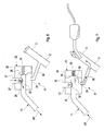
Fig. 8 zeigt eine vergrößerte Ausschnittsdarstellung ausFig. 6 und 7 . - Die in den Figuren nur teilweise dargestellte Kraftstoffanlage ist für ein Kraftfahrzeug mit einem Verbrennungsmotor bestimmt. Die Kraftstoffanlage umfasst einen druckdichten Kraftstofftank 1, der zum Betanken mit einem Einfüllrohr 2 mit einem druckdicht verschließbaren Einfüllstutzen 3 und einer Klappe 4 am unteren Ende versehen ist.
- Der Kraftstofftank 1 ist mit einer Tankentlüftungseinrichtung ausgestattet, die beim Betanken des Kraftfahrzeugs sowie bei einem Anstieg der Umgebungstemperatur eine Entlüftung des Kraftstofftanks 1 gestattet.
- Innerhalb des Tanks 1 umfasst die Tankentlüftungseinrichtung ein in einem Gas- oder Kopfraum 5 angeordnetes Tankentlüftungs- und Füllstandsbegrenzungsventil 6, sowie eine Flüssigkeitsfalle 7 mit einem Labyrinth 8 und einem unteren Kraftstoffsammelraum 9, die durch eine als Saugleitung und als interne Tankentlüftungsleitung dienende Leitung 10 mit dem Ventil 6 verbunden ist. In die Flüssigkeitsfalle 7 mündet von oben her eine externe Be- und Entlüftungsleitung 11, die oberhalb der Flüssigkeitsfalle 7 aus dem Tank 1 herausgeführt ist. Außerhalb des Tanks 1 umfasst die Tankentlüftungseinrichtung ein Tankabsperr- oder Tankisolierventil 12 und einen mit diesem verbundenen Aktivkohlefilter 13 (
Fig. 4 ). - Das Tankabsperr- oder Tankisolierventil 12 ist normalerweise geschlossen und wird zur Entlüftung des Kraftstofftanks 1 geöffnet, um während des Betankens des Kraftstofftanks 1 aus dem Gas- oder Kopfraum 5 verdrängtes Gas oder Gasgemisch in die Umgebung abzuführen. Außerdem wird das Tankabsperr- oder Tankisolierventil 12 zur Tankentlüftung unter der Steuerung eines Motorsteuergeräts des Verbrennungsmotors geöffnet, wenn der Druck im Tank 1 zum Beispiel infolge eines Anstiegs der Umgebungstemperatur einen einstellbaren Überdruck-Schwellenwert übersteigt.
- Der Aktivkohlefilter 13 verhindert, dass bei der Entlüftung des Kraftstofftanks 1 flüchtige Kohlenwasserstoffe (HC) in dem aus dem Tank 1 ausströmenden Gas oder Gasgemisch in die Umgebung gelangen und enthält zu diesem Zweck eine Füllung aus Aktivkohle, welche die flüchtigen Kohlenwasserstoffe (HC) absorbiert. Der Aktivkohlefilter 13 wird regeneriert, indem Umgebungsluft durch den Aktivkohlefilter 13 hindurch in einen Ansaugtrakt des Verbrennungsmotors angesaugt wird, um den Filter 13 zu spülen und die flüchtigen Kohlenwasserstoffe in den Brennräumen des Verbrennungsmotors zu verbrennen.
- Die Flüssigkeitsfalle 7 bildet einen Flüssigkeitsabscheider, der bei der Entlüftung des Kraftstofftanks 1 verhindert, dass von dem ausströmenden Gas oder Gasgemisch flüssiger Kraftstoff zum Aktivkohlefilter 13 mitgeführt wird. Der abgeschiedene flüssige Kraftstoff sammelt sich im Kraftstoffsammelraum 9 im unteren Teil der Flüssigkeitsfalle 7. Auf eine nähere Beschreibung des zur Abscheidung dienenden Labyrinths 8 wird verzichtet, da der Aufbau derselbe wie bei herkömmlichen Flüssigkeitsfallen 7 ist.
- Da zu viel flüssiger Kraftstoff in der Flüssigkeitsfalle 7 eine Betankung des Kraftfahrzeugs verhindert, muss die Flüssigkeitsfalle 7 bzw. deren Kraftstoffsammelraum 9 regelmäßig entleert werden. Dazu wird im Gas- oder Kopfraum 5 des Kraftstofftanks 1 ein Unterdruck erzeugt, d.h. eine negative Druckdifferenz zwischen dem Druck im Gas- oder Kopfraum 5 und dem Druck in der Flüssigkeitsfalle 7. Dieser Unterdruck wird durch die Leitung 10 an der Flüssigkeitsfalle 7 angelegt, wodurch der im Sammelraum 9 befindliche flüssige Kraftstoff mindestens teilweise durch die Leitung 10 und das Tankentlüftungs- und Füllstandsbegrenzungsventil 6 in den Gas- oder Kopfraum 5 abgesaugt wird.
- Um eine optimale Absaugung des Kraftstoffs aus dem Sammelraum 9 zu gewährleisten, kann die Leitung 10 zwischen dem Ventil 6 und der Flüssigkeitsfalle 7 im Gas- oder Kopfraum 5 einen Verteiler 14 umfassen, in dem sich die Leitung 10 in mehrere Zweigleitungen 15 verzweigt, wie am besten in
Fig. 2 dargestellt. Die Zweigleitungen 15 weisen einen kleineren Leitungsdurchmesser von etwa 8 mm auf. - Wie am besten in
Fig. 1 und3 dargestellt, erstrecken sich die Zweigleitungen 15 vom Verteiler 14 aus nach unten bis unter einen Boden 16 des Sammelraums 9, von wo aus ihre Endabschnitte 17 durch den Boden 16 hindurch nach oben in die Flüssigkeitsfalle 7 eintreten. Die vertikal ausgerichteten Endabschnitte 17 erstrecken sich als Tauchrohre durch den im Sammelraum 9 befindlichen Kraftstoff hindurch nach oben bis in die Nähe einer oberen Begrenzungswand 18 der Flüssigkeitsfalle 7, wo sie oberhalb des Kraftstoffspiegels in der Flüssigkeitsfalle 7 münden. In einem geringen Abstand oberhalb des Bodens 16 weisen die Endabschnitte 17 jeweils eine seitliche Bohrung 19 mit kleinen Öffnungsquerschnitt auf, durch die flüssiger Kraftstoff aus dem Sammelraum 9 in die Zweigleitungen 15 eintreten kann. - Die Abmessungen der Flüssigkeitsfalle 7 bzw. des Sammelraums sind auf die Kraftstoffmengen ausgelegt, die bei einer Heißdynamikfahrt des Kraftfahrzeugs anfallen können. Um einen Druckanstieg in der Flüssigkeitsfalle 7 zu verhindern, kann die Be- und Entlüftungsleitung 11 ein Expansionsvolumen 20 umfassen.
- Wenn im Gas- oder Kopfraum 5 ein "Überdruck" herrscht, d.h. wenn eine positive Druckdifferenz zwischen dem Gas- oder Kopfraum 5 und dem Inneren der Flüssigkeitsfalle 7 vorhanden ist, zum Beispiel wenn bei einem Anstieg der Umgebungstemperatur oder beim Betanken der Druck im Gas- oder Kopfraum 5 ansteigt, wird Gas oder Gasgemisch aus dem Gas- oder Kopfraum 5 durch die als Entlüftungsleitung wirkende Leitung 10 in die Flüssigkeitsfalle 7 gedrückt, wie durch die Pfeile pÜ in
Fig. 3 angezeigt. Bei geöffnetem Tankabsperr- oder Tankisolierventil 12 kann das Gas oder Gasgemisch von dort durch die Leitung 11 und den Aktivkohlefilter 13 in die Umgebung austreten. - Wenn hingegen im Gas- oder Kopfraum 5 ein "Unterdruck" herrscht, d.h. wenn eine negative Druckdifferenz zwischen dem Gas- oder Kopfraum 5 und dem Inneren der Flüssigkeitsfalle 7 vorhanden ist, wird flüssiger Kraftstoff aus dem Sammelraum 9 durch die als Saugleitung wirkende Leitung 10 aus der Flüssigkeitsfalle 7 in den Gas- oder Kopfraum 5 gesaugt, wie durch die Pfeile pU in
Fig. 3 angezeigt. Diese Druckdifferenz wird gezielt zur Absaugung von flüssigem Kraftstoff aus der Flüssigkeitsfalle 7 ausgenutzt, indem der im Gas- oder Kopfraum 5 erzeugte Unterdruck durch die Leitung 10 an der Flüssigkeitsfalle 7 angelegt wird. Dadurch wird der durch die Bohrung 19 in die Leitung 10 bzw. in die Zweigleitungen 15 eingetretene Kraftstoff in Richtung des Gas- oder Kopfraums 5 gesaugt, woraufhin weiterer Kraftstoff durch die Bohrung 19 in die Leitung 10 bzw. die Zweigleitungen 15 nachströmt. - Der Unterdruck wird zum Beispiel erzeugt, wenn sich der Tank 1 infolge eines Absinkens der Umgebungstemperatur abkühlt oder wenn der Kraftstoffspiegel im Tank 1 durch Verbrauch von Kraftstoff im Verbrennungsmotor absinkt. Wenn dieser Unterdruck ausreichend hoch ist, so dass er den hydrostatischen Druck einer Kraftstoffsäule mit einer Höhe H übersteigt, wird die Flüssigkeitsfalle 7 ohne zusätzliche unterstützende Maßnahmen entleert. Wie in
Fig. 4 dargestellt, entspricht die Höhe H der Höhendifferenz zwischen dem höchsten und dem tiefsten Punkt der Leitung 10. - Wenn der Unterdruck zur Entleerung der Flüssigkeitsfalle nicht ausreicht, kann als unterstützende Maßnahme das Tankabsperr- oder Tankisolierventil 12 geöffnet werden, wenn auch zwischen dem Inneren der Flüssigkeitsfalle 7 und der Umgebung eine negative Druckdifferenz vorhanden ist. Wie in
Fig. 4 dargestellt, wird dadurch die negative Druckdifferenz zwischen dem Gas- oder Kopfraum 5 und dem Inneren der Flüssigkeitsfalle 7 verstärkt. Durch den zusätzlichen Unterdruck sowie durch die in die Flüssigkeitsfalle 7 einströmende Umgebungsluft (Pfeil L inFig. 4 ) wird zusätzlicher Kraftstoff aus der Flüssigkeitsfalle 7 in den Gas- oder Kopfraum 5 gefördert. - Die Regelung des Öffnens und Schließens des Tankabsperr- oder Tankisolierventils 5 zur Unterstützung der Entleerung der Flüssigkeitsfalle wird nachfolgend unter Bezugnahme auf
Fig. 5a und 5b anhand zweier Regelschleifen erläutert, wobei der Unterdruck im Gas- oder Kopfraum 5 inFig. 5a durch den Kraftstoffverbrauch des Verbrennungsmotors und inFig. 5b durch natürliche Abkühlung des Kraftstofftanks 1 erzeugt wird. - In
Fig. 5a wird in einem ersten Schritt S1 nach dem Start der Regelschleife festgestellt, ob die Druckdifferenz zwischen dem Umgebungsdruck und dem Druck im Gas- oder Kopfraum 5 ausreicht, um den Kraftstoff aus der Flüssigkeitsfalle 7 über die Höhe H in den Gas- oder Kopfraum 5 zu fördern. Wenn dies der Fall ist, wird in einem zweiten Schritt S2 das Tankabsperr- oder Tankisolierventil 12 geöffnet, so dass Luft aus der Umgebung in die Flüssigkeitsfalle 7 strömen und dabei flüssigen Kraftstoff aus dem Sammelraum 9 in Richtung des Kopf- oder Gasraums 5 drücken kann. Sobald die Flüssigkeitsfalle 7 leer ist und der Druck im Gas- oder Kopfraum 5 dem Umgebungsdruck entspricht, wird in einem dritten Schritt S3 das Tankabsperr- oder Tankisolierventil 12 wieder geschlossen. Die Regelschleife kehrt dann zum Start zurück. - In
Fig. 5b wird in einem ersten Schritt S1 festgestellt, ob während einer dem Start der vorangehenden Heißdynamikfahrt, die häufig zu einer Befüllung der Flüssigkeitsfalle 7 mit flüssigem Kraftstoff führt, die Temperatur des Kraftstofftanks 1 einen vorgegebenen Temperaturschwellenwert TS überschritten hat und ob eine Tankdruckregelung aktiv ist. Wenn beides der Fall ist, wird in einem zweiten Schritt S2 festgestellt, ob die aktuelle Temperatur TIst um ein vorgegebenes Maß unterhalb des Temperaturschwellenwerts TS liegt. Wenn dies der Fall ist, wird daraus geschlossen, dass die Druckdifferenz zwischen dem Umgebungsdruck und dem Druck im Gas- oder Kopfraum 5 ausreicht, um den Kraftstoff aus der Flüssigkeitsfalle 7 über die Höhe H in den Gas- oder Kopfraum 5 zu fördern. Dann wird in einem dritten Schritt S3 das Tankabsperr- oder Tankisolierventil 12 geöffnet, so dass Luft aus der Umgebung in die Flüssigkeitsfalle 7 strömen und dabei flüssigen Kraftstoff aus dem Sammelraum 9 in Richtung des Kopf- oder Gasraums 5 drücken kann. Sobald die Flüssigkeitsfalle 7 leer ist und der Druck im Gas- oder Kopfraum 5 dem Umgebungsdruck entspricht, wird in einem vierten Schritt S4 das Tankabsperr- oder Tankisolierventil 12 wieder geschlossen. Die Regelschleife kehrt dann zum Start zurück. - Die
Figuren 6 bis 8 zeigen Teile einer Kraftstoffanlage, bei der zwischen dem Einfüllrohr 2 oder dem Einfüllstutzen 3 und der Be- und Entlüftungsleitung 11 eine Verbindung 21 besteht. Wie inFig. 6 und 7 dargestellt, umfasst diese Verbindung 21 ein Ventil 22, mit dem im Falle eines Unterdrucks in der Flüssigkeitsfalle 7 ein Zurücksaugen von Kraftstoff aus dem Einfüllrohr 3 in die Flüssigkeitsfalle 7 vermieden werden kann. - Das Ventil 22 besitzt ein Ventilgehäuse 23 mit einem ersten Anschluss 24, der durch die Leitung 11 mit der Flüssigkeitsfalle 7 kommuniziert, einen zweiten Anschluss 25, der durch eine Verbindungsleitung 26 mit dem Einfüllstutzen 3 oder Einfüllrohr 2 kommuniziert, und einen dritten Anschluss 27, der direkt mit der Umgebung kommuniziert. Das Ventil 22 enthält weiter eine verformbare Membran 28, die in einer ersten Stellung (
Fig. 6 ) von einer Feder 29 gegen eine stirnseitige Öffnung 30 der in das Gehäuse 23 ragenden Leitung 11 angepresst wird und diese verschließt, und die in einer zweiten Stellung (Fig. 7 ) von der Öffnung 30 abgehoben ist. Vom dritten Anschluss 27 aus erstreckt sich ein Rohr 31 durch das Ventilgehäuse 23 hindurch bis zu der Leitung 11 und mündet seitlich in diese ein. An der Einmündung ist ein leichtes Verschlusselement 32 vorgesehen, das auf und ab beweglich ist und sich infolge seines Eigengewichts in eine inFig. 6 dargestellte untere Endstellung bewegt, wenn die Membran 28 in ihrer Schließstellung die Öffnung 30 verschließt und damit die Verbindung zwischen der Leitung 11 und dem Einfüllstutzen 3 unterbricht. In dieser Stellung kann bei einer Entleerung der Flüssigkeitsfalle 7 durch einen Unterdruck im Gas- oder Kopfraum 5 Luft aus der Umgebung durch das Rohr 31 in die Entlüftungsleitung 11 und die Flüssigkeitsfalle 7 nachströmen, so dass aus dem Einfüllstutzen 3 bzw. Einfüllrohr 2 kein Kraftstoff angesaugt werden kann. - Wenn der Kraftstofftank 1 bei geöffnetem Einfüllstutzen 3 betankt wird, wie in
Fig. 7 dargestellt, drückt hingegen das aus dem Kopf- oder Gasraum 5 verdrängte und durch die Flüssigkeitsfalle 7 in die Leitung 11 strömende Gas oder Gasgemisch die Membran 28 entgegen der Kraft der Feder 29 in ihre Offenstellung, in der das Gas oder Gasgemisch durch die Verbindungsleitung 26 in den Einfüllstutzen 3 strömen kann. Dabei wird das Verschlusselement 32 angehoben und verschließt das Rohr 31, so dass dort kein Gas oder Gasgemisch in die Umgebung austreten kann. -
- 1
- Kraftstofftank
- 2
- Einfüllrohr
- 3
- Einfüllstutzen
- 4
- Klappe
- 5
- Gas- oder Kopfraum
- 6
- Tankentlüftungs- und Füllstandsbegrenzungsventil
- 7
- Flüssigkeitsfalle
- 8
- Labyrinth
- 9
- Kraftstoffsammelraum
- 10
- Saugleitung
- 11
- externe Be- und Entlüftungsleitung
- 12
- Tankabsperr- oder Tankisolierventil
- 13
- Aktivkohlefilter
- 14
- Verteiler
- 15
- Zweigleitungen
- 16
- Boden
- 17
- Endabschnitte
- 18
- obere Begrenzungswand
- 19
- Bohrung
- 20
- Expansionsvolumen
- 21
- Verbindung
- 22
- Ventil
- 23
- Ventilgehäuse
- 24
- erster Anschluss
- 25
- zweiter Anschluss
- 26
- Verbindungsleitung
- 27
- dritter Anschluss
- 28
- Membran
- 29
- Feder
- 30
- Öffnung
- 31
- Rohr
- 32
- Verschlusselement
Claims (13)
- Verfahren zur Absaugung von flüssigem Kraftstoff aus einer Flüssigkeitsfalle (7) in einem Kraftstofftank (1) eines Kraftfahrzeugs, in der bei einer Entlüftung des Kraftstofftanks (1) flüssiger Kraftstoff abgeschieden und in einem Sammelraum (9) gesammelt wird, dadurch gekennzeichnet, dass ein in einem Gas- oder Kopfraum des Kraftstofftanks (1) erzeugter Unterdruck durch eine Saugleitung (10) an der Flüssigkeitsfalle (7) angelegt und der im Sammelraum (9) befindliche flüssige Kraftstoff mindestens teilweise durch die Saugleitung (10) in den Gas- oder Kopfraum (5) abgesaugt wird.
- Verfahren nach Anspruch 1, dadurch gekennzeichnet, dass der Unterdruck im Gas- oder Kopfraum (5) bei gasdicht geschlossenem Kraftstofftank (1) durch Abkühlung des Kraftstofftanks (1) erzeugt wird.
- Verfahren nach Anspruch 1 oder 2, dadurch gekennzeichnet, dass der Unterdruck im Gas- oder Kopfraum (5) bei gasdicht geschlossenem Kraftstofftank (1) durch Verbrauch von Kraftstoff in einem Verbrennungsmotor des Kraftfahrzeugs erzeugt wird.
- Verfahren nach Anspruch 1, dadurch gekennzeichnet, dass der Unterdruck im Gas- oder Kopfraum (5) durch Absaugung von Gas oder Gasgemisch aus dem Gasoder Kopfraum (5) erzeugt wird.
- Verfahren nach Anspruch 4, dadurch gekennzeichnet, dass das Gas oder Gasgemisch in einen Ansaugtrakt eines Verbrennungsmotors des Kraftfahrzeugs abgesaugt wird.
- Verfahren nach einem der vorangehenden Ansprüche, dadurch gekennzeichnet, dass das Absaugen des flüssigen Kraftstoffs aus der Flüssigkeitsfalle (7) durch Öffnen eines geschlossenen Tankabsperr- oder Tankisolierventils (12) unterstützt wird.
- Kraftstoffanlage für ein Kraftfahrzeug, mit einem Kraftstofftank (1), einer innerhalb des Kraftstofftanks (1) angeordneten Flüssigkeitsfalle (7) zur Abscheidung von flüssigem Kraftstoff bei einer Entlüftung des Kraftstofftanks (1), wobei die Flüssigkeitsfalle (7) einen Sammelraum (9) für den abgeschiedenen Kraftstoff umfasst, dadurch gekennzeichnet, dass der Gas- oder Kopfraum (5) des Kraftstofftanks (1) durch eine mit dem Sammelraum (9) kommunizierende Saugleitung (10) mit der Flüssigkeitsfalle (7) verbunden ist.
- Kraftstoffanlage nach Anspruch 7, dadurch gekennzeichnet, dass das im Gasoder Kopfraum (5) befindliche Ende der Leitung (10) mit einem Tankentlüftungs- und Füllstandsbegrenzungsventil (6) versehen ist.
- Kraftstoffanlage nach Anspruch 7 oder 8, dadurch gekennzeichnet, dass sich die Leitung (10) vor dem Eintritt in den Sammelraum (9) in mehrere parallele Zweigleitungen (15) mit kleinerem Leitungsquerschnitt verzweigt.
- Kraftstoffanlage nach einem der Ansprüche 7 bis 9, dadurch gekennzeichnet, dass sich ein Ende der Leitung (10) oder der Zweigleitungen (15) innerhalb der Flüssigkeitsfalle (7) nach oben durch den Sammelraum (9) erstreckt, oberhalb des Sammelraums (9) in Innere der Flüssigkeitsfalle (7) mündet und innerhalb des Sammelraums (9) eine seitliche Öffnung (19) aufweist.
- Kraftstoffanlage nach einem der Ansprüche 7 bis 10, dadurch gekennzeichnet, dass die Flüssigkeitsfalle (7) durch eine Entlüftungsleitung (11) mit einem Aktivkohlefilter (13) verbunden ist und dass die Entlüftungsleitung (11) ein Expansionsvolumen (20) und/oder ein Tankabsperr- oder Tankisolierventil (12) enthält.
- Kraftstoffanlage nach einem der Ansprüche 7 bis 11, gekennzeichnet durch ein selbsttätig arbeitendes Ventil (22) zwischen der Flüssigkeitsfalle (7) und einem Einfüllstutzen (3) oder Einfüllrohr (2) des Kraftstofftanks (1), das einen mit der Flüssigkeitsfalle (7) kommunizierende ersten Anschluss (24), einen mit dem Einfüllstutzen (3) oder Einfüllrohr (2) kommunizierenden zweiten Anschluss (25), und einen mit der Umgebung kommunizierenden dritten Anschluss (27) umfasst.
- Kraftstoffanlage nach einem der Ansprüche 7 bis 12, gekennzeichnet durch eine mit einem Absperrventil versehene Absaugleitung zwischen dem Gas- oder Kopfraum (5) des Kraftstofftanks (1) und einem Ansaugtrakt eines Verbrennungsmotors des Kraftfahrzeugs.
Applications Claiming Priority (1)
| Application Number | Priority Date | Filing Date | Title |
|---|---|---|---|
| DE102014007694.6A DE102014007694B4 (de) | 2014-05-23 | 2014-05-23 | Verfahren zur Absaugung von flüssigem Kraftstoff aus einer zur Abscheidung des flüssigen Kraftstoffs dienenden Flüssigkeitsfalle in einem Kraftstofftank eines Kraftfahrzeugs, sowie Kraftstoffanlage für ein Kraftfahrzeug |
Publications (2)
| Publication Number | Publication Date |
|---|---|
| EP2946961A1 true EP2946961A1 (de) | 2015-11-25 |
| EP2946961B1 EP2946961B1 (de) | 2017-08-02 |
Family
ID=53189553
Family Applications (1)
| Application Number | Title | Priority Date | Filing Date |
|---|---|---|---|
| EP15001384.5A Active EP2946961B1 (de) | 2014-05-23 | 2015-05-07 | Verfahren zur absaugung von flüssigem kraftstoff aus einer zur abscheidung des flüssigen kraftstoffs dienenden flüssigkeitsfalle in einem kraftstofftank eines kraftfahrzeugs, sowie kraftstoffanlage für ein kraftfahrzeug |
Country Status (4)
| Country | Link |
|---|---|
| US (1) | US9631586B2 (de) |
| EP (1) | EP2946961B1 (de) |
| CN (1) | CN105089883B (de) |
| DE (1) | DE102014007694B4 (de) |
Families Citing this family (6)
| Publication number | Priority date | Publication date | Assignee | Title |
|---|---|---|---|---|
| DE102016109271A1 (de) * | 2016-05-20 | 2017-11-23 | Dr. Ing. H.C. F. Porsche Aktiengesellschaft | Filterbleeding-Messanordnung und Tankbleeding-Messanordnung |
| DE102016211160A1 (de) * | 2016-06-22 | 2017-12-28 | Röchling Automotive SE & Co. KG | Füllkopf für einen Betriebsflüssigkeitstank mit Gas- und Flüssigkeits-Ventilkörper |
| DE102016216860A1 (de) | 2016-09-06 | 2018-03-08 | Kautex Textron Gmbh & Co. Kg | Verfahren zur Innendrucksteuerung eines Betriebsflüssigkeitsbehälters und Betriebsflüssigkeitsbehältersystem mit Innendrucksteuerung |
| US11493000B1 (en) * | 2021-04-29 | 2022-11-08 | Ford Global Technologies, Llc | System and method for controlling flow in a fuel recirculation line |
| US11518238B1 (en) | 2021-10-19 | 2022-12-06 | Ford Global Technologies, Llc | System and method for controlling flow in a fuel recirculation line |
| US11698037B1 (en) | 2022-04-08 | 2023-07-11 | Ford Global Technologies, Llc | Fuel system for a vehicle and method of controlling |
Citations (7)
| Publication number | Priority date | Publication date | Assignee | Title |
|---|---|---|---|---|
| US5431144A (en) * | 1992-08-28 | 1995-07-11 | Toyota Jidosha Kabushiki Kaisha | Evaporated fuel control apparatus |
| DE19925728A1 (de) * | 1999-06-07 | 2000-12-21 | Benteler Werke Ag | Kraftstoffversorgungsanlage |
| EP1518739A2 (de) | 2003-09-29 | 2005-03-30 | Alfmeier Präzision Ag Baugruppen und Systemlösungen | Kraftfahrzeugtank mit Entlüftungssystem |
| DE102007016765A1 (de) * | 2007-04-07 | 2008-10-09 | Audi Ag | Verfahren zum Entleeren eines flüssigen Kraftstoff zurückhaltenden Kraftstoffauffanggefäßes einer Tankentlüftungsanlage und Tankentlüftungsanlage |
| DE102008025304A1 (de) * | 2007-06-01 | 2009-02-12 | Ti Automotive Technology Center Gmbh | Flüssigkeitsabscheider und entlüftete Kraftstofftankanordnung |
| DE102011106006A1 (de) * | 2011-06-30 | 2013-01-03 | Audi Ag | Verfahren zum Betreiben eines Kraftstoffsystems sowie Kraftstoffsystem |
| US20140123961A1 (en) * | 2012-11-07 | 2014-05-08 | Ford Global Technologies, Llc | Evaporative emission control |
Family Cites Families (12)
| Publication number | Priority date | Publication date | Assignee | Title |
|---|---|---|---|---|
| US3698160A (en) * | 1970-07-16 | 1972-10-17 | Chrysler Corp | Motor vehicle fuel tank venting |
| EP0648637A1 (de) * | 1993-09-15 | 1995-04-19 | General Motors Corporation | Vorrichtung zum Einfangen von Dämpfen |
| US6000426A (en) * | 1997-12-19 | 1999-12-14 | Walbro Corporation | Fuel system for reducing fuel vapor |
| FR2776273B1 (fr) * | 1998-03-18 | 2000-05-19 | Solvay | Circuit de mise a l'air pour reservoir a liquide |
| US6557581B2 (en) * | 2001-03-01 | 2003-05-06 | Raviv Precision Injection Molding | Liquid fuel trap |
| DE10148057A1 (de) * | 2001-09-28 | 2003-04-17 | Daimler Chrysler Ag | Vorrichtung zum Verflüssigen von dampfförmigen Kraftstoff-Fraktionen in Kraftstoffbehältern |
| JP3876753B2 (ja) * | 2002-04-17 | 2007-02-07 | トヨタ自動車株式会社 | 蒸発燃料処理装置 |
| US7168414B2 (en) * | 2004-09-03 | 2007-01-30 | Federal Mogul World Wide, Inc. | Marine vapor separator with bypass line |
| US7779820B2 (en) * | 2007-07-27 | 2010-08-24 | Ti Group Automotive Systems, L.L.C. | Liquid separator |
| DE102010055320A1 (de) * | 2010-12-21 | 2012-06-21 | Audi Ag | Kraftstoffsystem |
| DE102010055318B4 (de) * | 2010-12-21 | 2025-06-12 | Audi Ag | Verfahren und Einrichtung zur Steuerung des Drucks im Inneren eines Kraftstofftanks |
| DE102010055310A1 (de) * | 2010-12-21 | 2012-06-21 | Audi Ag | Kraftstoffsystem sowie Verfahren zum Betreiben eines Kraftstoffsystems |
-
2014
- 2014-05-23 DE DE102014007694.6A patent/DE102014007694B4/de not_active Expired - Fee Related
-
2015
- 2015-05-07 EP EP15001384.5A patent/EP2946961B1/de active Active
- 2015-05-22 US US14/720,011 patent/US9631586B2/en active Active
- 2015-05-22 CN CN201510264308.1A patent/CN105089883B/zh active Active
Patent Citations (7)
| Publication number | Priority date | Publication date | Assignee | Title |
|---|---|---|---|---|
| US5431144A (en) * | 1992-08-28 | 1995-07-11 | Toyota Jidosha Kabushiki Kaisha | Evaporated fuel control apparatus |
| DE19925728A1 (de) * | 1999-06-07 | 2000-12-21 | Benteler Werke Ag | Kraftstoffversorgungsanlage |
| EP1518739A2 (de) | 2003-09-29 | 2005-03-30 | Alfmeier Präzision Ag Baugruppen und Systemlösungen | Kraftfahrzeugtank mit Entlüftungssystem |
| DE102007016765A1 (de) * | 2007-04-07 | 2008-10-09 | Audi Ag | Verfahren zum Entleeren eines flüssigen Kraftstoff zurückhaltenden Kraftstoffauffanggefäßes einer Tankentlüftungsanlage und Tankentlüftungsanlage |
| DE102008025304A1 (de) * | 2007-06-01 | 2009-02-12 | Ti Automotive Technology Center Gmbh | Flüssigkeitsabscheider und entlüftete Kraftstofftankanordnung |
| DE102011106006A1 (de) * | 2011-06-30 | 2013-01-03 | Audi Ag | Verfahren zum Betreiben eines Kraftstoffsystems sowie Kraftstoffsystem |
| US20140123961A1 (en) * | 2012-11-07 | 2014-05-08 | Ford Global Technologies, Llc | Evaporative emission control |
Also Published As
| Publication number | Publication date |
|---|---|
| EP2946961B1 (de) | 2017-08-02 |
| US20150337777A1 (en) | 2015-11-26 |
| DE102014007694B4 (de) | 2024-01-11 |
| CN105089883A (zh) | 2015-11-25 |
| US9631586B2 (en) | 2017-04-25 |
| CN105089883B (zh) | 2018-04-06 |
| DE102014007694A1 (de) | 2015-11-26 |
Similar Documents
| Publication | Publication Date | Title |
|---|---|---|
| EP2946961B1 (de) | Verfahren zur absaugung von flüssigem kraftstoff aus einer zur abscheidung des flüssigen kraftstoffs dienenden flüssigkeitsfalle in einem kraftstofftank eines kraftfahrzeugs, sowie kraftstoffanlage für ein kraftfahrzeug | |
| DE102010055311B4 (de) | Einrichtung zur Entlüftung und Belüftung eines Kraftstofftanks | |
| DE102015012656B4 (de) | Verfahren zum Betreiben einer Kraftstoffanlage für ein Kraftfahrzeug sowie entsprechende Kraftstoffanlage | |
| DE102012213955B4 (de) | Kraftstoffspeichersystem für ein Fahrzeug | |
| DE102011011167B4 (de) | Kraftstoffsystem mit Einrichtungen zur Steuerung einer Saugstrahlpumpe in Abhängigkeit vom Kraftstoffpegel in einem Förder- oder Schwalltopf eines Kraftstofftanks | |
| DE102010033715A1 (de) | Ausgleichsbehälter für einen Kühlmittelkreislauf | |
| DE102008025304A1 (de) | Flüssigkeitsabscheider und entlüftete Kraftstofftankanordnung | |
| EP2103473B1 (de) | Belüftung für einen Reduktionsmittelbehälter | |
| DE1942963A1 (de) | Sicherheitsvorrichtung zur Be- und Entlueftung von geschlossenen Behaeltern | |
| DE112017004111T5 (de) | Füllgrenzen-Entlüftungsventil für Kraftstoffbehälter | |
| DE10209491A1 (de) | Kraftstoffbehälter mit Entlüftungssystem | |
| DE102007016765B4 (de) | Verfahren zum Entleeren eines flüssigen Kraftstoff zurückhaltenden Kraftstoffauffanggefäßes einer Tankentlüftungsanlage und Tankentlüftungsanlage | |
| DE112007003079T5 (de) | Entlüftungsventil | |
| DE102008014820A1 (de) | Kraftstofftank für Kraftfahrzeuge | |
| DE102010054960A1 (de) | Verfahren zur Betankung eines Kraftstofftanks, insbesondere eines Kraftfahrzeugs | |
| EP3452325B1 (de) | Tanksystem eines kraftfahrzeugs mit einem volumenveränderungselement | |
| EP3145743B1 (de) | Kraftstoffanlage für ein kraftfahrzeug mit einrichtungen zur entleerung einer flüssigkeitsfalle einer tankentlüftungseinrichtung bei einer schrägabstellung | |
| DE3913871A1 (de) | Kraftstofftank fuer kraftfahrzeuge und dergleichen | |
| EP2738031B1 (de) | Tanksystem für ein Kraftfahrzeug | |
| DE102009035345A1 (de) | Tiefentnahmegerät für Flüssigkeitsproben | |
| WO2013056886A2 (de) | Entlüftung eines kraftstofftanks über einen kraftstoffzufuhrpfad und einen luftzufuhrpfad eines vebrennungsmotors | |
| DE4311470C2 (de) | Be- und Entlüftungseinrichtung eines Fahrzeug-Kraftstofftanks | |
| EP2008857B1 (de) | Kraftstofftank für Kraftfahrzeuge | |
| DE102009060588B3 (de) | Vorrichtung zum Ablauf von Flüssigkeiten | |
| DE102010048844A1 (de) | Kraftstofftank mit einem Tankeinlassventil |
Legal Events
| Date | Code | Title | Description |
|---|---|---|---|
| PUAI | Public reference made under article 153(3) epc to a published international application that has entered the european phase |
Free format text: ORIGINAL CODE: 0009012 |
|
| AK | Designated contracting states |
Kind code of ref document: A1 Designated state(s): AL AT BE BG CH CY CZ DE DK EE ES FI FR GB GR HR HU IE IS IT LI LT LU LV MC MK MT NL NO PL PT RO RS SE SI SK SM TR |
|
| AX | Request for extension of the european patent |
Extension state: BA ME |
|
| 17P | Request for examination filed |
Effective date: 20160525 |
|
| RBV | Designated contracting states (corrected) |
Designated state(s): AL AT BE BG CH CY CZ DE DK EE ES FI FR GB GR HR HU IE IS IT LI LT LU LV MC MK MT NL NO PL PT RO RS SE SI SK SM TR |
|
| 17Q | First examination report despatched |
Effective date: 20161005 |
|
| GRAP | Despatch of communication of intention to grant a patent |
Free format text: ORIGINAL CODE: EPIDOSNIGR1 |
|
| INTG | Intention to grant announced |
Effective date: 20170524 |
|
| RIN1 | Information on inventor provided before grant (corrected) |
Inventor name: HAGEN, HARALD |
|
| GRAS | Grant fee paid |
Free format text: ORIGINAL CODE: EPIDOSNIGR3 |
|
| GRAA | (expected) grant |
Free format text: ORIGINAL CODE: 0009210 |
|
| AK | Designated contracting states |
Kind code of ref document: B1 Designated state(s): AL AT BE BG CH CY CZ DE DK EE ES FI FR GB GR HR HU IE IS IT LI LT LU LV MC MK MT NL NO PL PT RO RS SE SI SK SM TR |
|
| REG | Reference to a national code |
Ref country code: CH Ref legal event code: EP Ref country code: AT Ref legal event code: REF Ref document number: 914046 Country of ref document: AT Kind code of ref document: T Effective date: 20170815 |
|
| REG | Reference to a national code |
Ref country code: IE Ref legal event code: FG4D Free format text: LANGUAGE OF EP DOCUMENT: GERMAN |
|
| REG | Reference to a national code |
Ref country code: DE Ref legal event code: R096 Ref document number: 502015001521 Country of ref document: DE |
|
| REG | Reference to a national code |
Ref country code: NL Ref legal event code: MP Effective date: 20170802 |
|
| REG | Reference to a national code |
Ref country code: LT Ref legal event code: MG4D |
|
| PG25 | Lapsed in a contracting state [announced via postgrant information from national office to epo] |
Ref country code: LT Free format text: LAPSE BECAUSE OF FAILURE TO SUBMIT A TRANSLATION OF THE DESCRIPTION OR TO PAY THE FEE WITHIN THE PRESCRIBED TIME-LIMIT Effective date: 20170802 Ref country code: NO Free format text: LAPSE BECAUSE OF FAILURE TO SUBMIT A TRANSLATION OF THE DESCRIPTION OR TO PAY THE FEE WITHIN THE PRESCRIBED TIME-LIMIT Effective date: 20171102 Ref country code: NL Free format text: LAPSE BECAUSE OF FAILURE TO SUBMIT A TRANSLATION OF THE DESCRIPTION OR TO PAY THE FEE WITHIN THE PRESCRIBED TIME-LIMIT Effective date: 20170802 Ref country code: HR Free format text: LAPSE BECAUSE OF FAILURE TO SUBMIT A TRANSLATION OF THE DESCRIPTION OR TO PAY THE FEE WITHIN THE PRESCRIBED TIME-LIMIT Effective date: 20170802 Ref country code: SE Free format text: LAPSE BECAUSE OF FAILURE TO SUBMIT A TRANSLATION OF THE DESCRIPTION OR TO PAY THE FEE WITHIN THE PRESCRIBED TIME-LIMIT Effective date: 20170802 Ref country code: FI Free format text: LAPSE BECAUSE OF FAILURE TO SUBMIT A TRANSLATION OF THE DESCRIPTION OR TO PAY THE FEE WITHIN THE PRESCRIBED TIME-LIMIT Effective date: 20170802 |
|
| PG25 | Lapsed in a contracting state [announced via postgrant information from national office to epo] |
Ref country code: BG Free format text: LAPSE BECAUSE OF FAILURE TO SUBMIT A TRANSLATION OF THE DESCRIPTION OR TO PAY THE FEE WITHIN THE PRESCRIBED TIME-LIMIT Effective date: 20171102 Ref country code: PL Free format text: LAPSE BECAUSE OF FAILURE TO SUBMIT A TRANSLATION OF THE DESCRIPTION OR TO PAY THE FEE WITHIN THE PRESCRIBED TIME-LIMIT Effective date: 20170802 Ref country code: IS Free format text: LAPSE BECAUSE OF FAILURE TO SUBMIT A TRANSLATION OF THE DESCRIPTION OR TO PAY THE FEE WITHIN THE PRESCRIBED TIME-LIMIT Effective date: 20171202 Ref country code: RS Free format text: LAPSE BECAUSE OF FAILURE TO SUBMIT A TRANSLATION OF THE DESCRIPTION OR TO PAY THE FEE WITHIN THE PRESCRIBED TIME-LIMIT Effective date: 20170802 Ref country code: GR Free format text: LAPSE BECAUSE OF FAILURE TO SUBMIT A TRANSLATION OF THE DESCRIPTION OR TO PAY THE FEE WITHIN THE PRESCRIBED TIME-LIMIT Effective date: 20171103 Ref country code: LV Free format text: LAPSE BECAUSE OF FAILURE TO SUBMIT A TRANSLATION OF THE DESCRIPTION OR TO PAY THE FEE WITHIN THE PRESCRIBED TIME-LIMIT Effective date: 20170802 Ref country code: ES Free format text: LAPSE BECAUSE OF FAILURE TO SUBMIT A TRANSLATION OF THE DESCRIPTION OR TO PAY THE FEE WITHIN THE PRESCRIBED TIME-LIMIT Effective date: 20170802 |
|
| PG25 | Lapsed in a contracting state [announced via postgrant information from national office to epo] |
Ref country code: RO Free format text: LAPSE BECAUSE OF FAILURE TO SUBMIT A TRANSLATION OF THE DESCRIPTION OR TO PAY THE FEE WITHIN THE PRESCRIBED TIME-LIMIT Effective date: 20170802 Ref country code: DK Free format text: LAPSE BECAUSE OF FAILURE TO SUBMIT A TRANSLATION OF THE DESCRIPTION OR TO PAY THE FEE WITHIN THE PRESCRIBED TIME-LIMIT Effective date: 20170802 Ref country code: CZ Free format text: LAPSE BECAUSE OF FAILURE TO SUBMIT A TRANSLATION OF THE DESCRIPTION OR TO PAY THE FEE WITHIN THE PRESCRIBED TIME-LIMIT Effective date: 20170802 |
|
| REG | Reference to a national code |
Ref country code: DE Ref legal event code: R097 Ref document number: 502015001521 Country of ref document: DE |
|
| PG25 | Lapsed in a contracting state [announced via postgrant information from national office to epo] |
Ref country code: IT Free format text: LAPSE BECAUSE OF FAILURE TO SUBMIT A TRANSLATION OF THE DESCRIPTION OR TO PAY THE FEE WITHIN THE PRESCRIBED TIME-LIMIT Effective date: 20170802 Ref country code: SM Free format text: LAPSE BECAUSE OF FAILURE TO SUBMIT A TRANSLATION OF THE DESCRIPTION OR TO PAY THE FEE WITHIN THE PRESCRIBED TIME-LIMIT Effective date: 20170802 Ref country code: EE Free format text: LAPSE BECAUSE OF FAILURE TO SUBMIT A TRANSLATION OF THE DESCRIPTION OR TO PAY THE FEE WITHIN THE PRESCRIBED TIME-LIMIT Effective date: 20170802 Ref country code: SK Free format text: LAPSE BECAUSE OF FAILURE TO SUBMIT A TRANSLATION OF THE DESCRIPTION OR TO PAY THE FEE WITHIN THE PRESCRIBED TIME-LIMIT Effective date: 20170802 |
|
| PLBE | No opposition filed within time limit |
Free format text: ORIGINAL CODE: 0009261 |
|
| STAA | Information on the status of an ep patent application or granted ep patent |
Free format text: STATUS: NO OPPOSITION FILED WITHIN TIME LIMIT |
|
| 26N | No opposition filed |
Effective date: 20180503 |
|
| PG25 | Lapsed in a contracting state [announced via postgrant information from national office to epo] |
Ref country code: SI Free format text: LAPSE BECAUSE OF FAILURE TO SUBMIT A TRANSLATION OF THE DESCRIPTION OR TO PAY THE FEE WITHIN THE PRESCRIBED TIME-LIMIT Effective date: 20170802 |
|
| PG25 | Lapsed in a contracting state [announced via postgrant information from national office to epo] |
Ref country code: MT Free format text: LAPSE BECAUSE OF FAILURE TO SUBMIT A TRANSLATION OF THE DESCRIPTION OR TO PAY THE FEE WITHIN THE PRESCRIBED TIME-LIMIT Effective date: 20170802 |
|
| REG | Reference to a national code |
Ref country code: CH Ref legal event code: PL |
|
| REG | Reference to a national code |
Ref country code: BE Ref legal event code: MM Effective date: 20180531 |
|
| PG25 | Lapsed in a contracting state [announced via postgrant information from national office to epo] |
Ref country code: MC Free format text: LAPSE BECAUSE OF FAILURE TO SUBMIT A TRANSLATION OF THE DESCRIPTION OR TO PAY THE FEE WITHIN THE PRESCRIBED TIME-LIMIT Effective date: 20170802 |
|
| REG | Reference to a national code |
Ref country code: IE Ref legal event code: MM4A |
|
| PG25 | Lapsed in a contracting state [announced via postgrant information from national office to epo] |
Ref country code: CH Free format text: LAPSE BECAUSE OF NON-PAYMENT OF DUE FEES Effective date: 20180531 Ref country code: LI Free format text: LAPSE BECAUSE OF NON-PAYMENT OF DUE FEES Effective date: 20180531 |
|
| PG25 | Lapsed in a contracting state [announced via postgrant information from national office to epo] |
Ref country code: LU Free format text: LAPSE BECAUSE OF NON-PAYMENT OF DUE FEES Effective date: 20180507 |
|
| PG25 | Lapsed in a contracting state [announced via postgrant information from national office to epo] |
Ref country code: IE Free format text: LAPSE BECAUSE OF NON-PAYMENT OF DUE FEES Effective date: 20180507 Ref country code: FR Free format text: LAPSE BECAUSE OF NON-PAYMENT OF DUE FEES Effective date: 20180531 |
|
| PG25 | Lapsed in a contracting state [announced via postgrant information from national office to epo] |
Ref country code: BE Free format text: LAPSE BECAUSE OF NON-PAYMENT OF DUE FEES Effective date: 20180531 |
|
| GBPC | Gb: european patent ceased through non-payment of renewal fee |
Effective date: 20190507 |
|
| PG25 | Lapsed in a contracting state [announced via postgrant information from national office to epo] |
Ref country code: TR Free format text: LAPSE BECAUSE OF FAILURE TO SUBMIT A TRANSLATION OF THE DESCRIPTION OR TO PAY THE FEE WITHIN THE PRESCRIBED TIME-LIMIT Effective date: 20170802 |
|
| PG25 | Lapsed in a contracting state [announced via postgrant information from national office to epo] |
Ref country code: GB Free format text: LAPSE BECAUSE OF NON-PAYMENT OF DUE FEES Effective date: 20190507 |
|
| PG25 | Lapsed in a contracting state [announced via postgrant information from national office to epo] |
Ref country code: PT Free format text: LAPSE BECAUSE OF FAILURE TO SUBMIT A TRANSLATION OF THE DESCRIPTION OR TO PAY THE FEE WITHIN THE PRESCRIBED TIME-LIMIT Effective date: 20170802 |
|
| PG25 | Lapsed in a contracting state [announced via postgrant information from national office to epo] |
Ref country code: HU Free format text: LAPSE BECAUSE OF FAILURE TO SUBMIT A TRANSLATION OF THE DESCRIPTION OR TO PAY THE FEE WITHIN THE PRESCRIBED TIME-LIMIT; INVALID AB INITIO Effective date: 20150507 Ref country code: CY Free format text: LAPSE BECAUSE OF FAILURE TO SUBMIT A TRANSLATION OF THE DESCRIPTION OR TO PAY THE FEE WITHIN THE PRESCRIBED TIME-LIMIT Effective date: 20170802 Ref country code: MK Free format text: LAPSE BECAUSE OF NON-PAYMENT OF DUE FEES Effective date: 20170802 |
|
| PG25 | Lapsed in a contracting state [announced via postgrant information from national office to epo] |
Ref country code: AL Free format text: LAPSE BECAUSE OF FAILURE TO SUBMIT A TRANSLATION OF THE DESCRIPTION OR TO PAY THE FEE WITHIN THE PRESCRIBED TIME-LIMIT Effective date: 20170802 |
|
| REG | Reference to a national code |
Ref country code: AT Ref legal event code: MM01 Ref document number: 914046 Country of ref document: AT Kind code of ref document: T Effective date: 20200507 |
|
| PG25 | Lapsed in a contracting state [announced via postgrant information from national office to epo] |
Ref country code: AT Free format text: LAPSE BECAUSE OF NON-PAYMENT OF DUE FEES Effective date: 20200507 |
|
| P01 | Opt-out of the competence of the unified patent court (upc) registered |
Effective date: 20230530 |
|
| PGFP | Annual fee paid to national office [announced via postgrant information from national office to epo] |
Ref country code: DE Payment date: 20250531 Year of fee payment: 11 |