EP2946676B1 - Apparatus for and method of temperature treatment of a product - Google Patents
Apparatus for and method of temperature treatment of a product Download PDFInfo
- Publication number
- EP2946676B1 EP2946676B1 EP14169409.1A EP14169409A EP2946676B1 EP 2946676 B1 EP2946676 B1 EP 2946676B1 EP 14169409 A EP14169409 A EP 14169409A EP 2946676 B1 EP2946676 B1 EP 2946676B1
- Authority
- EP
- European Patent Office
- Prior art keywords
- gas
- arrangement
- products
- temperature treatment
- bed
- Prior art date
- Legal status (The legal status is an assumption and is not a legal conclusion. Google has not performed a legal analysis and makes no representation as to the accuracy of the status listed.)
- Active
Links
Images

Classifications
-
- A—HUMAN NECESSITIES
- A23—FOODS OR FOODSTUFFS; TREATMENT THEREOF, NOT COVERED BY OTHER CLASSES
- A23B—PRESERVATION OF FOODS, FOODSTUFFS OR NON-ALCOHOLIC BEVERAGES; CHEMICAL RIPENING OF FRUIT OR VEGETABLES
- A23B2/00—Preservation of foods or foodstuffs, in general
- A23B2/90—Preservation of foods or foodstuffs, in general by drying or kilning; Subsequent reconstitution
- A23B2/95—Fluidised-bed drying
-
- A—HUMAN NECESSITIES
- A23—FOODS OR FOODSTUFFS; TREATMENT THEREOF, NOT COVERED BY OTHER CLASSES
- A23B—PRESERVATION OF FOODS, FOODSTUFFS OR NON-ALCOHOLIC BEVERAGES; CHEMICAL RIPENING OF FRUIT OR VEGETABLES
- A23B2/00—Preservation of foods or foodstuffs, in general
- A23B2/80—Freezing; Subsequent thawing; Cooling
- A23B2/803—Materials being transported through or in the apparatus, with or without shaping, e.g. in the form of powders, granules or flakes
-
- F—MECHANICAL ENGINEERING; LIGHTING; HEATING; WEAPONS; BLASTING
- F25—REFRIGERATION OR COOLING; COMBINED HEATING AND REFRIGERATION SYSTEMS; HEAT PUMP SYSTEMS; MANUFACTURE OR STORAGE OF ICE; LIQUEFACTION SOLIDIFICATION OF GASES
- F25D—REFRIGERATORS; COLD ROOMS; ICE-BOXES; COOLING OR FREEZING APPARATUS NOT OTHERWISE PROVIDED FOR
- F25D13/00—Stationary devices, e.g. cold-rooms
- F25D13/06—Stationary devices, e.g. cold-rooms with conveyors carrying articles to be cooled through the cooling space
- F25D13/067—Stationary devices, e.g. cold-rooms with conveyors carrying articles to be cooled through the cooling space with circulation of gaseous cooling fluid
-
- F—MECHANICAL ENGINEERING; LIGHTING; HEATING; WEAPONS; BLASTING
- F26—DRYING
- F26B—DRYING SOLID MATERIALS OR OBJECTS BY REMOVING LIQUID THEREFROM
- F26B21/00—Arrangements for supplying or controlling air or other gases for drying solid materials or objects
- F26B21/50—Ducting arrangements from the source of air or other gases to the materials or objects being dried
-
- F—MECHANICAL ENGINEERING; LIGHTING; HEATING; WEAPONS; BLASTING
- F26—DRYING
- F26B—DRYING SOLID MATERIALS OR OBJECTS BY REMOVING LIQUID THEREFROM
- F26B3/00—Drying solid materials or objects by processes involving the application of heat
- F26B3/02—Drying solid materials or objects by processes involving the application of heat by convection, i.e. heat being conveyed from a heat source to the materials or objects to be dried by a gas or vapour, e.g. air
- F26B3/06—Drying solid materials or objects by processes involving the application of heat by convection, i.e. heat being conveyed from a heat source to the materials or objects to be dried by a gas or vapour, e.g. air the gas or vapour flowing through the materials or objects to be dried
- F26B3/08—Drying solid materials or objects by processes involving the application of heat by convection, i.e. heat being conveyed from a heat source to the materials or objects to be dried by a gas or vapour, e.g. air the gas or vapour flowing through the materials or objects to be dried so as to loosen them, e.g. to form a fluidised bed
- F26B3/084—Drying solid materials or objects by processes involving the application of heat by convection, i.e. heat being conveyed from a heat source to the materials or objects to be dried by a gas or vapour, e.g. air the gas or vapour flowing through the materials or objects to be dried so as to loosen them, e.g. to form a fluidised bed with heat exchange taking place in the fluidised bed, e.g. combined direct and indirect heat exchange
-
- F—MECHANICAL ENGINEERING; LIGHTING; HEATING; WEAPONS; BLASTING
- F28—HEAT EXCHANGE IN GENERAL
- F28C—HEAT-EXCHANGE APPARATUS, NOT PROVIDED FOR IN ANOTHER SUBCLASS, IN WHICH THE HEAT-EXCHANGE MEDIA COME INTO DIRECT CONTACT WITHOUT CHEMICAL INTERACTION
- F28C3/00—Other direct-contact heat-exchange apparatus
- F28C3/10—Other direct-contact heat-exchange apparatus one heat-exchange medium at least being a fluent solid, e.g. a particulate material
- F28C3/12—Other direct-contact heat-exchange apparatus one heat-exchange medium at least being a fluent solid, e.g. a particulate material the heat-exchange medium being a particulate material and a gas, vapour, or liquid
- F28C3/16—Other direct-contact heat-exchange apparatus one heat-exchange medium at least being a fluent solid, e.g. a particulate material the heat-exchange medium being a particulate material and a gas, vapour, or liquid the particulate material forming a bed, e.g. fluidised, on vibratory sieves
-
- F—MECHANICAL ENGINEERING; LIGHTING; HEATING; WEAPONS; BLASTING
- F25—REFRIGERATION OR COOLING; COMBINED HEATING AND REFRIGERATION SYSTEMS; HEAT PUMP SYSTEMS; MANUFACTURE OR STORAGE OF ICE; LIQUEFACTION SOLIDIFICATION OF GASES
- F25D—REFRIGERATORS; COLD ROOMS; ICE-BOXES; COOLING OR FREEZING APPARATUS NOT OTHERWISE PROVIDED FOR
- F25D2317/00—Details or arrangements for circulating cooling fluids; Details or arrangements for circulating gas, e.g. air, within refrigerated spaces, not provided for in other groups of this subclass
- F25D2317/06—Details or arrangements for circulating cooling fluids; Details or arrangements for circulating gas, e.g. air, within refrigerated spaces, not provided for in other groups of this subclass with forced air circulation
- F25D2317/063—Details or arrangements for circulating cooling fluids; Details or arrangements for circulating gas, e.g. air, within refrigerated spaces, not provided for in other groups of this subclass with forced air circulation with air guides
Definitions
- the invention relates to an apparatus for temperature treatment of a bed of products, the apparatus comprising a product transportation arrangement for transporting said bed of products along a product path in said apparatus, a gas temperature treatment arrangement for altering the temperature of a gas being circulated through the gas temperature treatment arrangement, and a gas circulation arrangement for circulating said gas in said apparatus, through said gas temperature treatment arrangement and through said bed of products.
- the gas circulation arrangement is adapted to provide a flow of said gas from beneath said bed of products and through said bed of products such that a fluidised bed of products is formed.
- the invention also relates to a method of temperature treatment of a bed of products, comprising transporting said bed of products along a product path in a product transportation arrangement, circulating gas through said bed of products, as the bed of products is transported along said product path, by a gas circulation arrangement, altering the temperature of said gas by circulating said gas through a temperature treatment arrangement, and circulating a flow of said gas from beneath said products and through said bed of products such that a fluidised bed of products is formed.
- US 3,169,381 discloses a freezer for freezing products in a fluidised bed.
- the fluidised bed is divided into different zones along a product path from a product inlet to a product outlet of the freezer. It is disclosed how the flow of cold air is supplied from a common main supply and that each zone is provided with a respective fan in order to be able to control the flow of air in respective zone. It is disclosed how there is supplied a greater quantity of cooled gas at the supply end than at other points, with an aim to supply a greater quantity of air to the newly supplied products require than to the products further downstream in the freezer.
- This document also discloses an air bypass at the supply end. A fraction of the air that has passed the product bed is re-circulated by a fan back to the supply end of the product bed without passing the cooling coil. This is said to reduce frost accumulation within the vessel.
- US 4,281,521 discloses a freezer for freezing products in a fluidised bed on a conveyor.
- the conveyor is driven forwardly and is interrupted by at least one downward stepping movement, causing a thinning of the product bed and a rapid increase in air velocity to thus cool and to separate the food articles preventing them from freezing to one another.
- the food articles are thereafter subjected to deep bed mass fluidisation by blowing freezing air there through in a fluidised state.
- the freezer is divided into a first section for cooling the product and a second section deep freezing.
- the first section is provided with a cooling system basically comprising a cooling coil and a fan.
- the second section is provided with a cooling system basically comprising a cooling coil and a fan.
- WO 2005/073649 discloses an apparatus for freezing products in a fluidised bed.
- the apparatus comprises air directing means arranged to direct a flow of air so that a bed formed of said products in a trough has a first fluidisation in a pre-cooling zone of the trough and a second fluidisation in a freezing zone of the trough downstream of the pre-cooling zone, wherein the second fluidisation is more vigorous than the first and so vigorous that freezing together of adjoining products is counteracted.
- US 3,718,024 discloses an apparatus and method for the controlled cooling of steel rod.
- the apparatus includes two cooling sections in which a cooling medium comprising sand is provided in a fluidized bed for the cooling of the steel rod.
- the apparatus and method relates to an apparatus and method for freezing products.
- the apparatus and method relates to temperature treatment of food products.
- the apparatus and method relates to freezing of food products. Examples of such a product are vegetables, fruits, berries and shellfish.
- the invention may also be used in heating or drying applications.
- the apparatus is provided with two, along the product path successively arranged, zones, wherein said gas temperature treatment arrangement is common to both zones and is associated with both zones such that gas circulated through said common gas temperature treatment arrangement is circulated through said bed of products in both zones, and wherein at least one of the zones is provided with a gas flow bypass arrangement, and wherein said gas flow bypass arrangement being adapted to allow a fraction of the gas to bypass the common gas temperature treatment arrangement and to rejoin with gas that has been circulated through the common gas temperature treatment arrangement before the gas is circulated through said bed of products in said gas flow bypass arrangement provided zone, the apparatus thereby being adapted to allow the temperature of gas circulated through said bed of products in said gas flow bypass arrangement provided zone to be controlled to be different from the temperature of gas circulated through said bed of products in the other of the two zones associated with the common gas temperature treatment arrangement.
- the gas temperature treatment arrangement may be designed without having to consider the length (along the product path) of the zone in which the temperature of the gas is to be controlled or the length of the zone may be designed without having to consider the length of the gas temperature arrangement or arrangements in the apparatus.
- This design makes it possible to address the problem of products forming lumps or the product sticking to the apparatus in a robust and cost-effective manner.
- By controlling the temperature of the gas in this manner in the different zones it is possible, in e.g. freezing or cooling applications, to address the problem of the products forming lumps or the product sticking to the apparatus.
- a freezing application it has been found that by providing an inlet zone, a zone in which the products are introduced into the apparatus, with said gas flow bypass arrangement it is possible to reduce the cooling effect in this inlet zone while still making it possible to maintain the flow of gas necessary to provide the fluidised bed of products in this inlet zone.
- the inventive design allows for the possibility that the gas flow bypass arrangement may be closed (not allowing any gas to bypass the gas temperature treatment arrangement) in cases where the products does not have the tendency to stick to each other and thereby full temperature treatment effect may be provided along the full length.
- the design also makes it possible to in a robust and cost-effective manner to control the temperature in a specific zone for other reasons.
- an outlet zone a zone in which the products leave the apparatus, is provided with said gas flow bypass arrangement.
- Rapid heating at the inlet or rapid cooling to ambient temperature after the outlet may e.g. cause products to crack, burst or shrink in an uncontrolled manner.
- the invention may also be used to control the temperature of the gas in a more central zone within the apparatus, a zone not forming an inlet zone and not forming an outlet zone, and to thereby provide such a zone with a gas flow bypass arrangement. It may e.g. be useful to control the temperature in such a zone in order to influence the moisture content. It may also be useful to control the temperature in a zone where e.g. additional agitation, pulsating gas, a step in a conveyor or other means are provided for further improve breaking up of any lumps in the bed of products into individual products.
- a fluidised bed of products is formed.
- a bed of products When a bed of products is fluidised it begins to behave like a liquid.
- the individual products In a fluidised bed of products the individual products are subjected to a flow of gas from beneath such that the products at the bottom have a tendency to jump up and down or to levitate and to hit surrounding products in the bed of products.
- the flow of gas flows around the products at the bottom and affects products above such that they begin to jump or levitate and to hit surrounding products.
- the individual products moves around and continue to hit each other and to be affected by the flow of gas from beneath each product. The total result is that the bed of products begins to behave like a liquid.
- the bed of product By controlling the flow of gas it is possible to influence the behaviour of the bed of products. With an increased flow of gas the bed of product typically behaves like a liquid with decreased viscosity.
- the fluidisation may be improved by pulsation of the flow of gas and/or by agitating the bed of products.
- Each of said two zones may be provided with a gas flow bypass arrangement, wherein a gas flow bypass arrangement of one of the zones is operable independently from a gas flow bypass arrangement of the other zone.
- a gas flow bypass arrangement of one of the zones is operable independently from a gas flow bypass arrangement of the other zone.
- the two zones are the only zones of the apparatus.
- the apparatus comprises one or more further zones apart from said two zones.
- the one or more further zones may in turn be provided with a gas flow bypass arrangement.
- the invention offers a possibility to design the gas temperature treatment arrangement independently of the division of the apparatus into zones.
- One set-up may e.g. be that one gas temperature treatment arrangement is associated with two zones and another gas temperature treatment arrangement is associated with one or more other zones. This may e.g.
- a zone may also be associated with two gas temperature treatment arrangements.
- One set-up may be that the apparatus is provided with two gas temperature treatment arrangements each along half the length of the product path in the apparatus.
- a short zone (with or without bypass) at one end of the apparatus, this zone being associated with a first gas temperature treatment arrangement, and the other zone (with or without bypass) is a longer zone being associated both with the first (i.e. the common) and the second gas temperature treatment arrangement.
- the gas may be circulated in a flow having a main component transverse to the product path, and wherein the gas temperature treatment arrangement extends along the product path, and is, in a horizontal plane projection, positioned beside the product path.
- the distance the gas flows may be kept short, i.e. unnecessary pressure drops may be kept at a minimum. Since the gas temperature treatment arrangement is positioned beside the product path, the risk of products falling into the gas temperature treatment arrangement or the risk of ice from the gas treatment arrangement falling into the product has been significantly reduced in a robust and efficient manner.
- the gas flow may be directed and the apparatus may designed such that the gas in consecutive order is circulated through said bed of products, thereafter the gas is circulated through the gas temperature treatment arrangement, and thereafter the gas passes the gas circulation arrangement.
- the gas is dried while passing the gas temperature treatment arrangement (e.g. so-called cooling battery) before reaching the gas circulation arrangement (e.g. a fan) thereby reducing the risk of frost building up on the fan which introduces imbalances which in turn could course a complete mechanical or electrical breakdown of the fan.
- the gas flow bypass arrangement may be arranged such that gas from said gas flow bypass arrangement rejoins the gas from the gas temperature treatment arrangement in a direction having a component directed away from said gas circulation arrangement.
- One advantage of this is that in cooling or freezing application will moisture in the comparably moisture rich gas from the gas flow bypass arrangement be blown in a general direction away from the gas circulation arrangement (e.g. a fan) thereby reducing the risk of frost building up on the fan which introduces imbalances which in turn could course a complete mechanical or electrical breakdown of the fan.
- the gas circulation arrangement may, in a direction transverse to the product path and in a horizontal plane projection, be positioned between the product transportation arrangement and the gas temperature treatment arrangement. This positioning reduces the risk of products or e.g. frost from the gas temperature treatment arrangement (when acting as a cooling battery in a cooling for freezing application) to fall into the gas circulation arrangement.
- the gas circulation arrangement may in a vertical plane projection be positioned beneath the gas temperature treatment arrangement and beneath the product path of the product transportation arrangement. This makes it possible to design the apparatus with short flow paths, which reduces unnecessary pressure drops of the gas flow. By arranging the gas circulation arrangement beneath the product path, it is possible to blow gas from beneath through the bed of products with a minimum of pressure drop losses.
- the gas flow bypass arrangement may be arranged such that gas from said gas flow bypass arrangement rejoins the gas from the gas temperature treatment arrangement in a direction having a component directed along gravity.
- One advantage of this is that in cooling or freezing application will moisture in the comparably moisture rich gas from the gas flow bypass arrangement be blown in a direction downwardly thereby making use of gravity to separate moisture from the gas thereby reducing the risk of frost building up on the fan which introduces imbalances which in turn could course a complete mechanical or electrical breakdown of the fan.
- the gas flow bypass arrangement may be arranged such that gas from said gas flow bypass arrangement rejoins the gas from the gas temperature treatment arrangement in a direction having a component, preferably a main component, being on one hand transverse to a main flow direction of the gas from the gas temperature treatment arrangement and on the other hand transverse to the product path.
- a component preferably a main component
- One advantage of this is that it promotes mixing of gas from the gas flow bypass arrangement with the gas from the gas temperature treatment arrangement, while reducing mixing of gas intended for one zone with gas intended for a neighbouring zone.
- one preferred application of use of the apparatus is cooling of products in said bed of products, preferably cooling of food products, and most preferred freezing of food products.
- the method further comprises; providing two, along the product path successively arranged, zones; associating both zones with a common gas temperature treatment arrangement such that gas circulated through said common gas temperature treatment arrangement will be circulated through said bed of products in both zones, and providing at least one of the zones with a gas flow bypass arrangement; arranging said gas flow bypass arrangement such that it allows a fraction of said gas to bypass the gas temperature treatment arrangement and to rejoin with gas that has been circulated through said gas temperature treatment arrangement before the gas is circulated through said bed of products in said gas flow bypass arrangement provided zone, the method thereby allowing the temperature of gas circulated through said bed of products in said gas flow bypass arrangement provided zone to be controlled to be different from the temperature of gas circulated through said bed of products in the other of the two zones associated with said common gas temperature treatment arrangement.
- the gas temperature treatment arrangement may be designed without having to consider the length (along the product path) of the zone in which the temperature of the gas is to be controlled or the length of the zone may be designed without having to consider the length of the gas temperature arrangement or arrangements in the apparatus. Further advantages with the inventive method have been discussed in detail in relation to features also being present in the independent claim related to the apparatus.
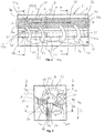
- the apparatus 1 is designed for temperature treatment of a bed B of products 8.
- the apparatus 1 comprises a housing 2 with two sidewalls 3a-b, two end walls 4a-b, a floor 6 and a ceiling 7.
- One of the end walls 4a is provided with an inlet opening 5a and the other end wall 4b is provided with an outlet opening 5b.
- the product 8 which is intended to be temperature treated is fed into the apparatus 1 via the inlet opening 5a, is transported through the apparatus 1 along a product path P, and is after temperature treatment removed from the apparatus 1 via the outlet opening 5b.
- the walls 3a-b, 4a-b, the floor 6 and the ceiling 7 of the housing 2 are preferably insulated to minimise undesired heat transfer between the inside of the housing 2 and the outside of the housing 2.
- the temperature of the outside of the housing 2 is ambient temperature, i.e. the temperature prevailing in the factory building and the inside of the housing 2 is significantly cooler in e.g. cooling or freezing applications or significantly hotter in e.g. heating, baking or drying applications.
- the apparatus 1 further comprises a gas temperature treatment arrangement 10, a product transportation arrangement 20, and a gas circulation arrangement 30.
- the gas temperature treatment arrangement 10 is adapted to alter the temperature of gas being circulated in a flow F2 of gas through the gas temperature treatment arrangement 10.
- the gas temperature treatment arrangement 10 is a so-called cooling battery for cooling the gas for cooling or freezing of the products 8.
- the cooling battery 10 is basically a heat exchanger where the gas is circulated past or through a plurality of cooler bodies in the cooling battery 10, such that the air is cooler after the cooling battery than before the cooling battery.
- the cooler bodies are a tubing system with fins attached to the tubing system and where the tubing system is designed as an evaporator for a cooling media circulated in the tubing system. The evaporation of the cooling media draws heat energy from the gas circulated through or past the cooling battery.
- the gas temperature treatment arrangement 10 is a well-defined more or less closed compartment with walls distinctly defining a flow path through the arrangement 10.
- the gas temperature treatment arrangement 10 does not comprise any compartment forming walls but are basically a set of heat exchange bodies located within in a geometric volume in space, and circulation of the gas through the gas temperature treatment arrangement relates to a circulation of gas through this geometric volume in space.
- the product transportation arrangement 20 is adapted to transport a fluidised bed B of products 8 through the apparatus along the product path P.
- the gas circulation arrangement 30 is adapted to circulate gas in the apparatus 1 through the gas temperature treatment arrangement 20 and upwardly through said bed B of products 8.
- the gas circulation arrangement 30 is adapted to provide a flow F1 of said gas from beneath the bed B of products 8 and through said bed B of products 8 such that a fluidised bed B of products 8 is formed.
- the product transportation arrangement 20 is a trough 21, with side walls 22, a bottom 23 and end walls 24a-b.
- the end wall 24b at the outlet opening 5b is lower than the side walls 22, thereby allowing the fluidised bed B to flow as a liquid in the trough 21 towards and over the end wall 24b for further transport by an adjoining apparatus.
- the bottom 23 of the trough 21 is foraminous, e.g. being formed of one or more plates provided with a plurality of through-going holes, thereby allowing gas to be circulated through the bottom 23 of the trough 21 and through the bed B of product 8 in the trough 21.
- the trough may be sloping downwardly, forwardly along the product path P in the direction P in which the products 8 in the bed B of products 8 is to be transported in order to facilitate the transport of the fluidised bed B of products 8.
- the product transportation arrangement 20 is provided with a conveyor, such as a belt conveyor, forming the bottom 23 of the trough 21.
- the conveyor e.g. the belt
- the conveyor is foraminous, thereby allowing gas to be circulated through the belt and through the bed B of products 8 on the conveyor.
- Such a design is e.g. disclosed in WO 2005/073649 .
- the conveyor e.g. the belt, may have its side edges folded upwardly to partly of fully form the side walls 22 of the trough 21.
- the complete trough 21 or at least the bottom 23, e.g. formed of one or more plates, is agitated back and forth along the product path P.
- the conveyor e.g. a belt conveyor
- the conveyor is agitated back and forth during its forward movement.
- the part of the conveyor belt in contact with the products 8 is moved in the desired transport direction while being agitated back and forth along the transport direction.
- the conveyor belt is agitated in an asymmetric manner such that there is an improved separation of the products and an improved fluidisation while there is still a resulting movement, of the part of the conveyor belt in contact with the products 8, in the direction of the desired transport direction of the products.
- the upwardly directed flow of gas flowing through the bottom 23 may be directed inclined in the direction in which the products 8 in the product bed B are to be transported. Such a flow of gas may be said to function also as a transportation arrangement 20.
- the flow of gas may be pulsated such that the flow of gas through the bed B of products 8 varies in short time periods in order to improve the fluidisation of the bed B of products 8.
- the product transportation arrangement 20 need not be or include any member which explicitly transports the products 8 along the product path P. Rather the product transportation arrangement 20 may in some cases, such as when the transportation arrangement 20 is formed as a trough 21, be considered more as an arrangement, which by its design provides physical boundaries for the fluidised bed B of products 8 to flow as a liquid along the product path P in the desired transportation direction.
- the apparatus 1 is provided with two zones Z1 and Z2.
- the zones Z1 and Z2 are successively arranged along the product path.
- Zone Z1 forms an inlet zone and zone Z2 forms an outlet zone.
- Zone Z1 is provided with a gas flow bypass arrangement 40.
- the gas flow bypass arrangement 40 in zone Z1 is adapted to allow a fraction F3 of the gas to bypass the common gas temperature treatment arrangement 10 and to rejoin with the fraction F2 of gas that has been circulated through the common gas temperature treatment arrangement 10 before the gas is circulated in a flow F1 through the bed B of products 8 in zone Z1.
- By providing a gas flow bypass arrangement 40 in zone Z1 it is possible to control the temperature of gas circulated through the bed B of products 8 in zone Z1 to be different from the temperature of gas circulated through said bed B of products 8 in zone 2 associated with the common gas temperature treatment arrangement.
- the gas circulation in zone Z1 is shown in the cross-sectional view of fig 2 .
- zone Z2 there is no gas flow bypass arrangement.
- the gas which has temperature treated the products 8 is circulated through the gas temperature treatment arrangement 10 and to the products 8 again.
- the gas circulation in zone Z2 is shown in the cross-sectional view of fig 3 .
- the products 8 in zone Z2 is subjected to a temperature treatment determined by the full temperature effect of the common gas temperature treatment arrangement 10 on the gas.
- the products 8 in zone Z1 is subjected to a temperature treatment which is lesser than the temperature treatment in zone Z2.
- the gas circulated through the bed B of products 8 is cooler in zone Z2, where there is no gas flow bypass arrangement 40, than the gas circulated through the bed B of products 8 in zone Z1, where there is a gas flow bypass arrangement 40.
- the gas circulation arrangement 30 is formed of an array of fans 31-35 successively arranged along the product path P.
- the zone Z1 being provided with a gas flow bypass arrangement 40 is associated with two fans 31 and 32.
- the zone Z1 being provided with a gas flow bypass arrangement 40 is associated with an integer number of fans.
- the demarcation zone is associated with a fan or fan arrangement drawing air intended for both zones.
- this latter would e.g. be achieved by having the gas flow bypass arrangement 40 to have an extension along the product path P ending half-way through the extension of the second fan 32 along the product path P.
- each of the two zones Z1 and Z2 provided with a gas flow bypass arrangement 40, 40b.
- the gas flow bypass arrangement 40 of zone Z1 is operable independently from the gas flow bypass arrangement 40b of zone Z2.
- This embodiment with a gas flow bypass arrangement 40b also in zone Z2 is indicated by the dashed line denoted 40b. If zone Z2 is provided with a gas flow bypass arrangement 40b and it is open, the gas flow will be as indicated in fig 2 also in zone Z2.
- the gas flow bypass arrangement 40 is an opening 41 in a wall section 42 otherwise closing the distance between the product transportation arrangement 20 and the gas temperature treatment arrangement 10.
- the opening has a rectangular shape with a longitudinal extension along the product path P with longitudinally extending side edges 42a-b and transversely extending end edges 43a-b.
- the side edges 42a-b and end edges 43a-b need not be straight and distinctly separated edges as in the rectangular shape. They may be curved and they may be smoothly adjoining each other.
- the shapes may e.g. be circular or ellipsoid. It is also conceivable that the opening 41 is divided into several openings successively arranged along the product path P.
- the gas flow bypass arrangement 40 comprises a hatch 44 which is operable between a closed state and an open state.
- the hatch 44 closes the opening 41 such that the gas flow bypass arrangement 40 is closed.
- there is no gas flow through the gas flow bypass arrangement i.e. the flow is as illustrated in fig 3 also in zone Z1 which is provided with the gas flow bypass arrangement 40.
- the hatch 44 does not close the opening 41 and the gas flow bypass arrangement 40 is open.
- a fraction F3 of the gas flows through the gas flow bypass arrangement 40, i.e. the flow is as illustrated in fig 2 in zone Z1 which is provided with the gas flow bypass arrangement.
- the hatch 44 is continuously or step-wise operable into one or a plurality of states between said open and closed states, thereby allowing the size of the fraction F3 through the gas flow bypass arrangement 40 and the size of the remaining fraction F2 through the gas temperature treatment arrangement 10 to be varied.
- the gas flow bypass arrangement is at least operable between a first state and a second state, wherein the first state allows a greater fraction of the gas to flow via the gas flow bypass arrangement compared to the second state, wherein the gas flow bypass arrangement preferably is continuously or step-wise operable into one or a plurality of states between said first and second states.
- the first state in this embodiment may be the most open state the gas flow bypass arrangement is capable of reaching.
- the gas flow bypass arrangement may be arranged to be able to reach an even more open state than the first state e.g. by removing any throttle or the like providing the operability between the first and second state.
- the second state may be a fully closed state.
- the second state may be a state where the gas flow bypass arrangement is still partly open. From such a partly open second state it may be possible to fully close the gas flow bypass arrangement e.g. by providing a separate member closing the gas flow bypass arrangement or by manually change the position of any throttle of the like providing the operability between the first and second state.
- the gas is circulated in a flow having a main component transverse to the product path P, and wherein the gas temperature treatment arrangement 10 extends along the product path P, and is, in a horizontal plane projection (a plane as shown in fig 1 ), positioned beside the product transportation arrangement 20.
- the gas flows in an essentially circular flow from the product transportation arrangement 20 to the gas temperature treatment arrangement 10 and back to the product transportation arrangement 20.
- the flow has a main component in the plane shown in fig 2 and fig 3 , i.e. a main component in a plane being transverse to the product path P.
- the gas flow is directed and the apparatus is designed such that the gas in consecutive order is circulated through said bed B of products 8, thereafter the gas is circulated through the gas temperature treatment arrangement 10, and thereafter the gas passes the gas circulation arrangement 30. Thereafter the gas is circulated through the bed B of products 8.
- the gas flow bypass arrangement 40 is arranged such that gas F4 from said gas flow bypass arrangement 40 rejoins the gas F5 from the gas temperature treatment arrangement 10 in a direction (indicated by the arrow F4) having a component directed away from said gas circulation arrangement 30 as viewed in a plane being transverse to the product path P.
- the gas F4 from said gas flow bypass arrangement 40 rejoins the gas F5 from the gas temperature treatment arrangement 10 in a direction (indicated by the arrow F4) in the preferred embodiment having a main component directed away from said gas circulation arrangement 30 as viewed in a plane being transverse to the product path P.
- the gas flow bypass arrangement 40 is arranged such that gas F3 from said gas flow bypass arrangement 40 rejoins the gas F4 from the gas temperature treatment arrangement 10 in a direction F4 having a component being transverse to a main flow direction F5 of the gas from the gas temperature treatment arrangement 10 and transverse to the product path P.
- the gas flow bypass arrangement 40 is arranged such that gas F3 from said gas flow bypass arrangement 40 rejoins the gas F4 from the gas temperature treatment arrangement 10 in a direction F4 in the preferred embodiment having a main component being transverse to a main flow direction F5 of the gas from the gas temperature treatment arrangement 10 and transverse to the product path P.
- the gas flow bypass arrangement 40 is arranged such that gas F4 from said gas flow bypass arrangement 40 rejoins the gas F5 from the gas temperature treatment arrangement 10 in a direction F4 having a component directed along gravity G.
- the fans 31-35 of the gas circulation arrangement 30 are, in a direction transverse to the product path P and in a horizontal plane projection (the plane of fig 4 ) positioned between the product transportation arrangement 20 and the gas temperature treatment arrangement 10. As shown in figs 2 and 3 , the fans 31-35 of the gas circulation arrangement 30 are in a vertical plane projection (the plane of figs 2 and 3 ) positioned beneath the gas temperature treatment arrangement 10 and beneath the product path P of the product transportation arrangement 20.
- the fans 31-35 are not located directly beneath the gas temperature treatment arrangement 10 and not directly beneath the product path P of the product transportation arrangement 20 but are at a lower level and in a horizontal direction between the gas temperature treatment arrangement 10 and the product path P of the product transportation arrangement 20.
- the fraction of flow (in volume/time unit) of gas F4 through the gas flow bypass arrangement 40 may be between 1% and 90% of the total flow F4+F5 of gas which has passed the gas flow bypass arrangement 40 and the gas temperature treatment arrangement 10 in the zone Z1 provided with the gas flow bypass arrangement 40.
- the temperature of the flow F1 of gas from beneath the bed B of products 8 and through said bed B of products 8 may be varied.
- the fraction of flow of gas F4 through the gas flow bypass arrangement 40 may be controlled by operating the hatch 44 into one of the plurality of states between the open and closed states.
- the operating of the hatch 44 into one of the plurality of states between the open and closed states may be controlled by means of a temperature regulator.
- the gas is air.
- the air has been filtered or otherwise cleaned to minimize introduction of contaminants.
- the preferred embodiment has e.g. been discussed in respect of a cooling or freezing application where the gas temperature treatment arrangement 10 is a so-called cooling battery for cooling the gas.
- the invention is e.g. also applicable for heating or drying applications where the gas temperature treatment arrangement will be heating the gas.
- zones each provided with an independently controlled gas flow bypass arrangement such that the temperature of the gas may be controlled to be different in respective zone compared to the temperature of the gas in the other zones provided with gas flow bypass arrangements.
- the zone(s) provided with gas flow bypass arrangement may be the inlet zone as in the disclosed embodiment.
- the zone provided with a gas flow bypass arrangement may be an outlet zone.
- it may be a central zone not forming an inlet or outlet zone.
- a plurality of zones provided with independently operable gas flow bypass arrangements may also be used to provide a controlled temperature profile along the product path.
Landscapes
- Engineering & Computer Science (AREA)
- Life Sciences & Earth Sciences (AREA)
- General Engineering & Computer Science (AREA)
- Mechanical Engineering (AREA)
- Chemical & Material Sciences (AREA)
- Wood Science & Technology (AREA)
- Microbiology (AREA)
- Zoology (AREA)
- Food Science & Technology (AREA)
- Polymers & Plastics (AREA)
- Thermal Sciences (AREA)
- Physics & Mathematics (AREA)
- Combustion & Propulsion (AREA)
- Furnace Details (AREA)
Priority Applications (2)
| Application Number | Priority Date | Filing Date | Title |
|---|---|---|---|
| PL14169409T PL2946676T3 (pl) | 2014-05-22 | 2014-05-22 | Urządzenie i sposób obróbki termicznej produktu |
| EP14169409.1A EP2946676B1 (en) | 2014-05-22 | 2014-05-22 | Apparatus for and method of temperature treatment of a product |
Applications Claiming Priority (1)
| Application Number | Priority Date | Filing Date | Title |
|---|---|---|---|
| EP14169409.1A EP2946676B1 (en) | 2014-05-22 | 2014-05-22 | Apparatus for and method of temperature treatment of a product |
Publications (2)
| Publication Number | Publication Date |
|---|---|
| EP2946676A1 EP2946676A1 (en) | 2015-11-25 |
| EP2946676B1 true EP2946676B1 (en) | 2017-09-06 |
Family
ID=50774661
Family Applications (1)
| Application Number | Title | Priority Date | Filing Date |
|---|---|---|---|
| EP14169409.1A Active EP2946676B1 (en) | 2014-05-22 | 2014-05-22 | Apparatus for and method of temperature treatment of a product |
Country Status (2)
| Country | Link |
|---|---|
| EP (1) | EP2946676B1 (pl) |
| PL (1) | PL2946676T3 (pl) |
Families Citing this family (1)
| Publication number | Priority date | Publication date | Assignee | Title |
|---|---|---|---|---|
| CN117029386B (zh) * | 2023-09-08 | 2025-07-08 | 山东奥诺能源科技股份有限公司 | 一种适用于热敏性物料的流化床干燥方法 |
Family Cites Families (8)
| Publication number | Priority date | Publication date | Assignee | Title |
|---|---|---|---|---|
| US3169381A (en) | 1964-04-13 | 1965-02-16 | Frigoscandia Ltd | Fluidized freezer |
| FR1473109A (fr) * | 1965-01-15 | 1967-03-17 | Hupp Corp | Procédé et installation pour la torréfaction du café et pour des applications analogues |
| US3718024A (en) * | 1971-02-12 | 1973-02-27 | Morgan Construction Co | Apparatus including a fluidized bed for cooling steel rod through transformation |
| DE2724037A1 (de) * | 1977-05-27 | 1978-12-07 | Hauni Werke Koerber & Co Kg | Vorrichtung zum trocknen eines kontinuierlich gefoerderten tabakstromes |
| US4281521A (en) | 1979-12-05 | 1981-08-04 | Refrigeration Engineering Corporation | Fluidized freezing |
| SE527465C2 (sv) | 2004-01-30 | 2006-03-14 | Frigoscandia Equipment Ab | Anordning och metod för infrysning av produkter i en fluidiserad bädd |
| DE102005015781A1 (de) * | 2005-04-01 | 2006-10-05 | Hauni Maschinenbau Ag | Verfahren und Vorrichtung zum Trocknen eines faserförmigen Gutes |
| PL2261583T3 (pl) * | 2009-06-08 | 2019-09-30 | John Bean Technologies Ab | Urządzenie do obróbki produktu |
-
2014
- 2014-05-22 EP EP14169409.1A patent/EP2946676B1/en active Active
- 2014-05-22 PL PL14169409T patent/PL2946676T3/pl unknown
Non-Patent Citations (1)
| Title |
|---|
| None * |
Also Published As
| Publication number | Publication date |
|---|---|
| PL2946676T3 (pl) | 2018-02-28 |
| EP2946676A1 (en) | 2015-11-25 |
Similar Documents
| Publication | Publication Date | Title |
|---|---|---|
| AU2008287045B2 (en) | Cross-flow spiral heat transfer system | |
| KR101916714B1 (ko) | 식품급속 개체냉동장치 | |
| US5170631A (en) | Combination cryogenic and mechanical freezer apparatus and method | |
| EP2274992B1 (en) | Cooling Mechanism For Use With a food Processing System | |
| US20120273165A1 (en) | Cross-flow spiral heat transfer apparatus with solid belt | |
| KR102341708B1 (ko) | 냉각 또는 냉동하기 위한 장치 및 방법 | |
| US2527542A (en) | Method and apparatus for freezing materials | |
| EP2946676B1 (en) | Apparatus for and method of temperature treatment of a product | |
| US20070169630A1 (en) | Thermal processing chamber and conveyor belt for use therein and method of processing product | |
| US9791201B1 (en) | Spiral chiller apparatus and method of chilling | |
| RU2036396C1 (ru) | Способ замораживания плодов и овощей и устройство для его осуществления | |
| DK178194B1 (da) | Apparat og fremgangsmåde til køling af produkter i et fluidiseret leje | |
| US5520006A (en) | Airflow and defrosting system for refrigeration systems and apparatus | |
| CZ288223B6 (en) | Apparatus for processing foodstuffs by air | |
| EP1866582A1 (en) | Impingement freezer | |
| EP2261583B1 (en) | Apparatus for treatment of a product | |
| RU2718982C1 (ru) | Устройство для замораживания в кипящем слое с нагреваемым впускным каналом | |
| KR102176270B1 (ko) | 개별 신선 냉동(Individual Fresh Frozen)을 이용한 닭고기 냉동 방법 및 장치 | |
| JP6818221B2 (ja) | 冷却装置 | |
| ES2899138T3 (es) | Aparatos de refrigeración de productos | |
| JP2009019851A (ja) | 冷却方法及び冷却装置 | |
| US20240361063A1 (en) | Product overblow management assembly | |
| WO1993019334A1 (en) | A chiller | |
| KR102176261B1 (ko) | 개별 신선 냉동(Individual Fresh Frozen)을 이용한 닭고기 냉동 방법 및 장치 | |
| RU2198358C2 (ru) | Скороморозильный аппарат для плодов, ягод и овощей |
Legal Events
| Date | Code | Title | Description |
|---|---|---|---|
| PUAI | Public reference made under article 153(3) epc to a published international application that has entered the european phase |
Free format text: ORIGINAL CODE: 0009012 |
|
| AK | Designated contracting states |
Kind code of ref document: A1 Designated state(s): AL AT BE BG CH CY CZ DE DK EE ES FI FR GB GR HR HU IE IS IT LI LT LU LV MC MK MT NL NO PL PT RO RS SE SI SK SM TR |
|
| AX | Request for extension of the european patent |
Extension state: BA ME |
|
| 17P | Request for examination filed |
Effective date: 20160525 |
|
| RBV | Designated contracting states (corrected) |
Designated state(s): AL AT BE BG CH CY CZ DE DK EE ES FI FR GB GR HR HU IE IS IT LI LT LU LV MC MK MT NL NO PL PT RO RS SE SI SK SM TR |
|
| GRAP | Despatch of communication of intention to grant a patent |
Free format text: ORIGINAL CODE: EPIDOSNIGR1 |
|
| STAA | Information on the status of an ep patent application or granted ep patent |
Free format text: STATUS: GRANT OF PATENT IS INTENDED |
|
| RIC1 | Information provided on ipc code assigned before grant |
Ipc: F26B 3/08 20060101ALI20170224BHEP Ipc: A23L 3/36 20060101AFI20170224BHEP Ipc: A23L 3/50 20060101ALI20170224BHEP Ipc: F28C 3/16 20060101ALI20170224BHEP Ipc: F25D 13/06 20060101ALI20170224BHEP |
|
| INTG | Intention to grant announced |
Effective date: 20170330 |
|
| GRAS | Grant fee paid |
Free format text: ORIGINAL CODE: EPIDOSNIGR3 |
|
| GRAA | (expected) grant |
Free format text: ORIGINAL CODE: 0009210 |
|
| STAA | Information on the status of an ep patent application or granted ep patent |
Free format text: STATUS: THE PATENT HAS BEEN GRANTED |
|
| AK | Designated contracting states |
Kind code of ref document: B1 Designated state(s): AL AT BE BG CH CY CZ DE DK EE ES FI FR GB GR HR HU IE IS IT LI LT LU LV MC MK MT NL NO PL PT RO RS SE SI SK SM TR |
|
| REG | Reference to a national code |
Ref country code: GB Ref legal event code: FG4D |
|
| REG | Reference to a national code |
Ref country code: CH Ref legal event code: EP Ref country code: AT Ref legal event code: REF Ref document number: 924902 Country of ref document: AT Kind code of ref document: T Effective date: 20170915 |
|
| REG | Reference to a national code |
Ref country code: IE Ref legal event code: FG4D |
|
| REG | Reference to a national code |
Ref country code: DE Ref legal event code: R096 Ref document number: 602014014045 Country of ref document: DE |
|
| REG | Reference to a national code |
Ref country code: SE Ref legal event code: TRGR |
|
| REG | Reference to a national code |
Ref country code: NL Ref legal event code: MP Effective date: 20170906 |
|
| REG | Reference to a national code |
Ref country code: LT Ref legal event code: MG4D |
|
| PG25 | Lapsed in a contracting state [announced via postgrant information from national office to epo] |
Ref country code: FI Free format text: LAPSE BECAUSE OF FAILURE TO SUBMIT A TRANSLATION OF THE DESCRIPTION OR TO PAY THE FEE WITHIN THE PRESCRIBED TIME-LIMIT Effective date: 20170906 Ref country code: HR Free format text: LAPSE BECAUSE OF FAILURE TO SUBMIT A TRANSLATION OF THE DESCRIPTION OR TO PAY THE FEE WITHIN THE PRESCRIBED TIME-LIMIT Effective date: 20170906 Ref country code: LT Free format text: LAPSE BECAUSE OF FAILURE TO SUBMIT A TRANSLATION OF THE DESCRIPTION OR TO PAY THE FEE WITHIN THE PRESCRIBED TIME-LIMIT Effective date: 20170906 Ref country code: NO Free format text: LAPSE BECAUSE OF FAILURE TO SUBMIT A TRANSLATION OF THE DESCRIPTION OR TO PAY THE FEE WITHIN THE PRESCRIBED TIME-LIMIT Effective date: 20171206 |
|
| REG | Reference to a national code |
Ref country code: AT Ref legal event code: MK05 Ref document number: 924902 Country of ref document: AT Kind code of ref document: T Effective date: 20170906 |
|
| PG25 | Lapsed in a contracting state [announced via postgrant information from national office to epo] |
Ref country code: LV Free format text: LAPSE BECAUSE OF FAILURE TO SUBMIT A TRANSLATION OF THE DESCRIPTION OR TO PAY THE FEE WITHIN THE PRESCRIBED TIME-LIMIT Effective date: 20170906 Ref country code: ES Free format text: LAPSE BECAUSE OF FAILURE TO SUBMIT A TRANSLATION OF THE DESCRIPTION OR TO PAY THE FEE WITHIN THE PRESCRIBED TIME-LIMIT Effective date: 20170906 Ref country code: RS Free format text: LAPSE BECAUSE OF FAILURE TO SUBMIT A TRANSLATION OF THE DESCRIPTION OR TO PAY THE FEE WITHIN THE PRESCRIBED TIME-LIMIT Effective date: 20170906 Ref country code: BG Free format text: LAPSE BECAUSE OF FAILURE TO SUBMIT A TRANSLATION OF THE DESCRIPTION OR TO PAY THE FEE WITHIN THE PRESCRIBED TIME-LIMIT Effective date: 20171206 Ref country code: GR Free format text: LAPSE BECAUSE OF FAILURE TO SUBMIT A TRANSLATION OF THE DESCRIPTION OR TO PAY THE FEE WITHIN THE PRESCRIBED TIME-LIMIT Effective date: 20171207 |
|
| PG25 | Lapsed in a contracting state [announced via postgrant information from national office to epo] |
Ref country code: NL Free format text: LAPSE BECAUSE OF FAILURE TO SUBMIT A TRANSLATION OF THE DESCRIPTION OR TO PAY THE FEE WITHIN THE PRESCRIBED TIME-LIMIT Effective date: 20170906 |
|
| PG25 | Lapsed in a contracting state [announced via postgrant information from national office to epo] |
Ref country code: CZ Free format text: LAPSE BECAUSE OF FAILURE TO SUBMIT A TRANSLATION OF THE DESCRIPTION OR TO PAY THE FEE WITHIN THE PRESCRIBED TIME-LIMIT Effective date: 20170906 Ref country code: RO Free format text: LAPSE BECAUSE OF FAILURE TO SUBMIT A TRANSLATION OF THE DESCRIPTION OR TO PAY THE FEE WITHIN THE PRESCRIBED TIME-LIMIT Effective date: 20170906 |
|
| PG25 | Lapsed in a contracting state [announced via postgrant information from national office to epo] |
Ref country code: SM Free format text: LAPSE BECAUSE OF FAILURE TO SUBMIT A TRANSLATION OF THE DESCRIPTION OR TO PAY THE FEE WITHIN THE PRESCRIBED TIME-LIMIT Effective date: 20170906 Ref country code: EE Free format text: LAPSE BECAUSE OF FAILURE TO SUBMIT A TRANSLATION OF THE DESCRIPTION OR TO PAY THE FEE WITHIN THE PRESCRIBED TIME-LIMIT Effective date: 20170906 Ref country code: IS Free format text: LAPSE BECAUSE OF FAILURE TO SUBMIT A TRANSLATION OF THE DESCRIPTION OR TO PAY THE FEE WITHIN THE PRESCRIBED TIME-LIMIT Effective date: 20180106 Ref country code: IT Free format text: LAPSE BECAUSE OF FAILURE TO SUBMIT A TRANSLATION OF THE DESCRIPTION OR TO PAY THE FEE WITHIN THE PRESCRIBED TIME-LIMIT Effective date: 20170906 Ref country code: AT Free format text: LAPSE BECAUSE OF FAILURE TO SUBMIT A TRANSLATION OF THE DESCRIPTION OR TO PAY THE FEE WITHIN THE PRESCRIBED TIME-LIMIT Effective date: 20170906 Ref country code: SK Free format text: LAPSE BECAUSE OF FAILURE TO SUBMIT A TRANSLATION OF THE DESCRIPTION OR TO PAY THE FEE WITHIN THE PRESCRIBED TIME-LIMIT Effective date: 20170906 |
|
| REG | Reference to a national code |
Ref country code: DE Ref legal event code: R097 Ref document number: 602014014045 Country of ref document: DE |
|
| PLBE | No opposition filed within time limit |
Free format text: ORIGINAL CODE: 0009261 |
|
| STAA | Information on the status of an ep patent application or granted ep patent |
Free format text: STATUS: NO OPPOSITION FILED WITHIN TIME LIMIT |
|
| PG25 | Lapsed in a contracting state [announced via postgrant information from national office to epo] |
Ref country code: DK Free format text: LAPSE BECAUSE OF FAILURE TO SUBMIT A TRANSLATION OF THE DESCRIPTION OR TO PAY THE FEE WITHIN THE PRESCRIBED TIME-LIMIT Effective date: 20170906 |
|
| 26N | No opposition filed |
Effective date: 20180607 |
|
| PG25 | Lapsed in a contracting state [announced via postgrant information from national office to epo] |
Ref country code: SI Free format text: LAPSE BECAUSE OF FAILURE TO SUBMIT A TRANSLATION OF THE DESCRIPTION OR TO PAY THE FEE WITHIN THE PRESCRIBED TIME-LIMIT Effective date: 20170906 |
|
| REG | Reference to a national code |
Ref country code: CH Ref legal event code: PL |
|
| GBPC | Gb: european patent ceased through non-payment of renewal fee |
Effective date: 20180522 |
|
| REG | Reference to a national code |
Ref country code: BE Ref legal event code: MM Effective date: 20180531 |
|
| PG25 | Lapsed in a contracting state [announced via postgrant information from national office to epo] |
Ref country code: MC Free format text: LAPSE BECAUSE OF FAILURE TO SUBMIT A TRANSLATION OF THE DESCRIPTION OR TO PAY THE FEE WITHIN THE PRESCRIBED TIME-LIMIT Effective date: 20170906 |
|
| REG | Reference to a national code |
Ref country code: IE Ref legal event code: MM4A |
|
| PG25 | Lapsed in a contracting state [announced via postgrant information from national office to epo] |
Ref country code: LI Free format text: LAPSE BECAUSE OF NON-PAYMENT OF DUE FEES Effective date: 20180531 Ref country code: CH Free format text: LAPSE BECAUSE OF NON-PAYMENT OF DUE FEES Effective date: 20180531 |
|
| PG25 | Lapsed in a contracting state [announced via postgrant information from national office to epo] |
Ref country code: LU Free format text: LAPSE BECAUSE OF NON-PAYMENT OF DUE FEES Effective date: 20180522 |
|
| PG25 | Lapsed in a contracting state [announced via postgrant information from national office to epo] |
Ref country code: IE Free format text: LAPSE BECAUSE OF NON-PAYMENT OF DUE FEES Effective date: 20180522 Ref country code: FR Free format text: LAPSE BECAUSE OF NON-PAYMENT OF DUE FEES Effective date: 20180531 Ref country code: GB Free format text: LAPSE BECAUSE OF NON-PAYMENT OF DUE FEES Effective date: 20180522 |
|
| PG25 | Lapsed in a contracting state [announced via postgrant information from national office to epo] |
Ref country code: BE Free format text: LAPSE BECAUSE OF NON-PAYMENT OF DUE FEES Effective date: 20180531 |
|
| PG25 | Lapsed in a contracting state [announced via postgrant information from national office to epo] |
Ref country code: MT Free format text: LAPSE BECAUSE OF NON-PAYMENT OF DUE FEES Effective date: 20180522 |
|
| PG25 | Lapsed in a contracting state [announced via postgrant information from national office to epo] |
Ref country code: TR Free format text: LAPSE BECAUSE OF FAILURE TO SUBMIT A TRANSLATION OF THE DESCRIPTION OR TO PAY THE FEE WITHIN THE PRESCRIBED TIME-LIMIT Effective date: 20170906 |
|
| PG25 | Lapsed in a contracting state [announced via postgrant information from national office to epo] |
Ref country code: PT Free format text: LAPSE BECAUSE OF FAILURE TO SUBMIT A TRANSLATION OF THE DESCRIPTION OR TO PAY THE FEE WITHIN THE PRESCRIBED TIME-LIMIT Effective date: 20170906 |
|
| PG25 | Lapsed in a contracting state [announced via postgrant information from national office to epo] |
Ref country code: HU Free format text: LAPSE BECAUSE OF FAILURE TO SUBMIT A TRANSLATION OF THE DESCRIPTION OR TO PAY THE FEE WITHIN THE PRESCRIBED TIME-LIMIT; INVALID AB INITIO Effective date: 20140522 Ref country code: MK Free format text: LAPSE BECAUSE OF NON-PAYMENT OF DUE FEES Effective date: 20170906 Ref country code: CY Free format text: LAPSE BECAUSE OF FAILURE TO SUBMIT A TRANSLATION OF THE DESCRIPTION OR TO PAY THE FEE WITHIN THE PRESCRIBED TIME-LIMIT Effective date: 20170906 |
|
| PG25 | Lapsed in a contracting state [announced via postgrant information from national office to epo] |
Ref country code: AL Free format text: LAPSE BECAUSE OF FAILURE TO SUBMIT A TRANSLATION OF THE DESCRIPTION OR TO PAY THE FEE WITHIN THE PRESCRIBED TIME-LIMIT Effective date: 20170906 |
|
| P01 | Opt-out of the competence of the unified patent court (upc) registered |
Effective date: 20230505 |
|
| REG | Reference to a national code |
Ref country code: DE Ref legal event code: R079 Ref document number: 602014014045 Country of ref document: DE Free format text: PREVIOUS MAIN CLASS: A23L0003360000 Ipc: A23B0002800000 |
|
| PGFP | Annual fee paid to national office [announced via postgrant information from national office to epo] |
Ref country code: SE Payment date: 20250326 Year of fee payment: 12 |
|
| PGFP | Annual fee paid to national office [announced via postgrant information from national office to epo] |
Ref country code: PL Payment date: 20250327 Year of fee payment: 12 |
|
| PGFP | Annual fee paid to national office [announced via postgrant information from national office to epo] |
Ref country code: DE Payment date: 20250325 Year of fee payment: 12 |