US2527542A - Method and apparatus for freezing materials - Google Patents
Method and apparatus for freezing materials Download PDFInfo
- Publication number
- US2527542A US2527542A US558378A US55837844A US2527542A US 2527542 A US2527542 A US 2527542A US 558378 A US558378 A US 558378A US 55837844 A US55837844 A US 55837844A US 2527542 A US2527542 A US 2527542A
- Authority
- US
- United States
- Prior art keywords
- trays
- air
- chamber
- elevator
- freezing
- Prior art date
- Legal status (The legal status is an assumption and is not a legal conclusion. Google has not performed a legal analysis and makes no representation as to the accuracy of the status listed.)
- Expired - Lifetime
Links
- 238000007710 freezing Methods 0.000 title description 65
- 230000008014 freezing Effects 0.000 title description 65
- 239000000463 material Substances 0.000 title description 26
- 238000000034 method Methods 0.000 title description 16
- 238000001816 cooling Methods 0.000 description 43
- 235000013305 food Nutrition 0.000 description 16
- 230000010006 flight Effects 0.000 description 13
- 239000007921 spray Substances 0.000 description 12
- 238000004891 communication Methods 0.000 description 11
- 238000007664 blowing Methods 0.000 description 9
- 230000018044 dehydration Effects 0.000 description 7
- 238000006297 dehydration reaction Methods 0.000 description 7
- 230000033001 locomotion Effects 0.000 description 5
- 230000008569 process Effects 0.000 description 5
- 230000002528 anti-freeze Effects 0.000 description 4
- 239000000969 carrier Substances 0.000 description 4
- 239000007788 liquid Substances 0.000 description 4
- 230000000630 rising effect Effects 0.000 description 3
- 238000012546 transfer Methods 0.000 description 3
- XLYOFNOQVPJJNP-UHFFFAOYSA-N water Substances O XLYOFNOQVPJJNP-UHFFFAOYSA-N 0.000 description 3
- 241000251468 Actinopterygii Species 0.000 description 2
- 241000196324 Embryophyta Species 0.000 description 2
- 230000009471 action Effects 0.000 description 2
- 230000008901 benefit Effects 0.000 description 2
- 230000001143 conditioned effect Effects 0.000 description 2
- 238000007791 dehumidification Methods 0.000 description 2
- 238000007599 discharging Methods 0.000 description 2
- 235000019688 fish Nutrition 0.000 description 2
- 238000010438 heat treatment Methods 0.000 description 2
- 208000020442 loss of weight Diseases 0.000 description 2
- 235000013372 meat Nutrition 0.000 description 2
- 239000003507 refrigerant Substances 0.000 description 2
- 238000005507 spraying Methods 0.000 description 2
- 230000007480 spreading Effects 0.000 description 2
- 238000010257 thawing Methods 0.000 description 2
- 235000013311 vegetables Nutrition 0.000 description 2
- 241000287828 Gallus gallus Species 0.000 description 1
- 235000003095 Vaccinium corymbosum Nutrition 0.000 description 1
- 240000000851 Vaccinium corymbosum Species 0.000 description 1
- 235000017537 Vaccinium myrtillus Nutrition 0.000 description 1
- 230000001464 adherent effect Effects 0.000 description 1
- 235000021014 blueberries Nutrition 0.000 description 1
- 235000013330 chicken meat Nutrition 0.000 description 1
- 239000012141 concentrate Substances 0.000 description 1
- 238000010790 dilution Methods 0.000 description 1
- 239000012895 dilution Substances 0.000 description 1
- 235000013399 edible fruits Nutrition 0.000 description 1
- 230000000694 effects Effects 0.000 description 1
- 239000012595 freezing medium Substances 0.000 description 1
- 235000021022 fresh fruits Nutrition 0.000 description 1
- 235000013611 frozen food Nutrition 0.000 description 1
- 230000005484 gravity Effects 0.000 description 1
- 239000011810 insulating material Substances 0.000 description 1
- 238000009413 insulation Methods 0.000 description 1
- 235000000396 iron Nutrition 0.000 description 1
- 238000012423 maintenance Methods 0.000 description 1
- 239000002184 metal Substances 0.000 description 1
- 230000000737 periodic effect Effects 0.000 description 1
- 244000144977 poultry Species 0.000 description 1
- 235000013594 poultry meat Nutrition 0.000 description 1
- 238000004321 preservation Methods 0.000 description 1
- 238000012545 processing Methods 0.000 description 1
- 238000005057 refrigeration Methods 0.000 description 1
- 238000009877 rendering Methods 0.000 description 1
- 230000008439 repair process Effects 0.000 description 1
- 230000000979 retarding effect Effects 0.000 description 1
- 238000013517 stratification Methods 0.000 description 1
- 230000032258 transport Effects 0.000 description 1
- 235000021269 warm food Nutrition 0.000 description 1
- 238000010792 warming Methods 0.000 description 1
Images


Classifications
-
- F—MECHANICAL ENGINEERING; LIGHTING; HEATING; WEAPONS; BLASTING
- F25—REFRIGERATION OR COOLING; COMBINED HEATING AND REFRIGERATION SYSTEMS; HEAT PUMP SYSTEMS; MANUFACTURE OR STORAGE OF ICE; LIQUEFACTION SOLIDIFICATION OF GASES
- F25D—REFRIGERATORS; COLD ROOMS; ICE-BOXES; COOLING OR FREEZING APPARATUS NOT OTHERWISE PROVIDED FOR
- F25D13/00—Stationary devices, e.g. cold-rooms
- F25D13/06—Stationary devices, e.g. cold-rooms with conveyors carrying articles to be cooled through the cooling space
- F25D13/067—Stationary devices, e.g. cold-rooms with conveyors carrying articles to be cooled through the cooling space with circulation of gaseous cooling fluid
-
- A—HUMAN NECESSITIES
- A23—FOODS OR FOODSTUFFS; TREATMENT THEREOF, NOT COVERED BY OTHER CLASSES
- A23L—FOODS, FOODSTUFFS, OR NON-ALCOHOLIC BEVERAGES, NOT COVERED BY SUBCLASSES A21D OR A23B-A23J; THEIR PREPARATION OR TREATMENT, e.g. COOKING, MODIFICATION OF NUTRITIVE QUALITIES, PHYSICAL TREATMENT; PRESERVATION OF FOODS OR FOODSTUFFS, IN GENERAL
- A23L3/00—Preservation of foods or foodstuffs, in general, e.g. pasteurising, sterilising, specially adapted for foods or foodstuffs
- A23L3/36—Freezing; Subsequent thawing; Cooling
- A23L3/361—Freezing; Subsequent thawing; Cooling the materials being transported through or in the apparatus, with or without shaping, e.g. in form of powder, granules, or flakes
-
- F—MECHANICAL ENGINEERING; LIGHTING; HEATING; WEAPONS; BLASTING
- F25—REFRIGERATION OR COOLING; COMBINED HEATING AND REFRIGERATION SYSTEMS; HEAT PUMP SYSTEMS; MANUFACTURE OR STORAGE OF ICE; LIQUEFACTION SOLIDIFICATION OF GASES
- F25D—REFRIGERATORS; COLD ROOMS; ICE-BOXES; COOLING OR FREEZING APPARATUS NOT OTHERWISE PROVIDED FOR
- F25D2317/00—Details or arrangements for circulating cooling fluids; Details or arrangements for circulating gas, e.g. air, within refrigerated spaces, not provided for in other groups of this subclass
- F25D2317/06—Details or arrangements for circulating cooling fluids; Details or arrangements for circulating gas, e.g. air, within refrigerated spaces, not provided for in other groups of this subclass with forced air circulation
- F25D2317/068—Details or arrangements for circulating cooling fluids; Details or arrangements for circulating gas, e.g. air, within refrigerated spaces, not provided for in other groups of this subclass with forced air circulation characterised by the fans
- F25D2317/0683—Details or arrangements for circulating cooling fluids; Details or arrangements for circulating gas, e.g. air, within refrigerated spaces, not provided for in other groups of this subclass with forced air circulation characterised by the fans the fans not of the axial type
Definitions
- This invention relates to a method and apparatus for freezing materials, and more particularly to such method and apparatus by which the foods are rapidly frozen through contact with 'a stream of air moved rapidly over the materials being conveyed through a freezing chamber and maintained at a'temperature substantially below the freezing point of the-articles being frozen.
- the invention is essentially directed to the preservation of fresh fruit, vegetables, fish, poul- "try, meat and the like in open or packaged form by rapid freezing through direct contact with a low temperature *air stream to retain to a high degree the fresh taste, color, aroma, texture and other qualities of the preserved product when subsequently thawed.
- One of the principal objects of the invention is to reduce to a minimum the amount of handling required in carrying out the freezing process, of the materials, both before and after freezing, and also of the trays or other carriers used.
- Another object of the invention is to reduce to a minimum the alternate cooling and heating of the carriers used in conveying the materials through the freezing chamber, the heating occurring while the carriers are being returned to the inlet end of the freezing chamber for refilling.
- Another object of the invention is to provide such a method and apparatus which can be advantageously used in conjunction with a food storage room or hopper forthe food storage room located above the ground floor of the building.
- Another object is to provide such a process and apparatus which is continuous, that is, the materials to be frozen are continuously fed to the apparatus and the frozen materials continuously removed therefrom.
- Another important object is to provide such a method and apparatus in which there is aminimum loss of weight of the product, due to dehydration while being processed.
- Another object is to provide such apparatus in which there is no substantial loss of refrigeration either through the loss of cold air at the inlet or outlet of the freezing chamber or through the introduction of damp warm air which would tend to frost'the coils.
- Another object is to provide such apparatus which employs standard air cooling units which can be purchased at low cost and readily incorporated inthe apparatus, thereby to reduce the cost of the apparatus as well as reducing the cost of maintenance as compared with systems in which specially designed cooling and air handling Sysn tems are required.
- Another most important object of the invention is to provide such a system in which every tray or carrier for the food receives exactly the same treatment as to velocity, volume, humidity and temperature of the air as every other tray, this providing a high degree of uniformity of the frozen product as well as permitting of exact control.
- Another object is to provide such apparatus in which the flow of air is crosswise of the product throughout and in which the distribution of this crosswise flow of air is effected by the food itself thereby to obtain high freezing efiiciency and uniformity of treatment.
- Another object of the invention is to eliminate the necessity for all access doors in connection with the handling of the product.
- Another object is to provide a system in which there is a true countercurrent application of the air to the articles being frozen, that is, the application of the coldest air to the coldest leaving product and the warmest air to the warm entering product.
- Another object is to treat the product in two zones, the first zone being designed to remove any moisture from the product without frosting up of the cooling coils so that dry cooling coils can be used in the second zone without undue frosting of the drycoils.
- Another object is to provide such a two stage process in which two relatively small and independently operated air cooling units can be used for the two stages, this permitting the apparatus to be produced at low cost; rendering it subject to exact control; and facilitating repair and replacement of parts.
- Another object is to provide such apparatus in which the floor space occupied is reduced to a minimum.
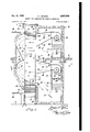
- Fig. 1 is a vertical sectional view through apparatus embodying the present invention.
- Figs. 2 and 3 are horizontal sectional views, taken on the correspondingly numbered lines of Fig. 1.
- the trays are removed from the truck and the frozen food emptied from each tray into a hopper, each emptied tray being replaced on the truck.
- the frozen material from the hopper is then automatically elevated to the second floor freezer storage room, it having been found undesirable to locate such freezer storage rooms on the ground floor both because of the working fioor space lost and also because of the danger of heaving of the floors.
- the truck with empty trays is then pushed back to the loading station where the trays are removed, refilled and replaced to repeat the cycle of operations.
- the freezing apparatus forming the subject of the present invention occupies the first and second floors of the building in which the frozen product is stored, the first floor being indicated at 5 and preferabl being at ground level so that the articles to be frozen can be transported directly to the freezing apparatus without intermediate handling and the second floor being indicated at 6.
- the apparatus forming the subject of the present invention is arranged within a housing I ⁇ of thermal insulating material, the quick freezing of the products being accomplished at relatively low temperatures and it being hence important to provide adequate insulation and thereby obtain efficient operation.
- an elevator shaft A which extends through an opening 9 in the second floor and has a horizontal inlet opening II] at the lower end of the housing 8 and a horizontal outlet opening I I at the upper end of the housing 8.
- the housing 8 On one side of the elevator shaft A and on the ground floor 5 the housing 8 encloses a chamber B in which a non-frosting, low temperature cooling unit, indicated generally at I2, is arranged.
- the housing 8 On the second floor 6 the housing 8 encloses a chamber C which is arranged directly above the chamber B and contains a dry coil, low temperature cooling unit indicated generally at I3.
- the chambers B and C are in communication with the same side of the elevator shaft A.
- the housing 8 On the opposite side of the elevator shaft from the chamber 0 the housing 8 encloses an air return chamber or passage D which is in communication with this elevator shaft A and which returns the air discharged through the elevator shaft by the cooling unit I3 to the inlet thereof, as hereinafter described. Similarly, below the chamber D, and on the opposite side of the elevator shaft A from the chamber B the housing 8 encloses an air return chamber or passage E which is in communication with this elevator shaft A and which returns the air discharged through the elevator shaft b the non-frosting low temperature cooling unit I2 to the inlet thereof, as hereinafter described.
- the articles are frozen while being conveyed upwardly on an elevator which traverses the elevator shaft A and which is preferably constructed as follows:
- each side of the elevator shaft A is arranged a pair of endless chains I5, the upper ends of which pass around sprockets It on a pair of horizontal shafts I8 and the lower ends of which pass around sprockets 20 fast to a pair of shafts 2I.
- the upper shafts I8 are arranged above the horizontal outlet opening I I of he ele- 4 vator shaft and are preferably housed within a hood 22 having an outlet 23 in one side wall through which the frozen product is removed from the elevator.
- the lower shafts 2! are arranged below the horizontal inlet opening I!) of the elevator shaft A so as to permit of loading the elevator on the ground floor from a position outside of the housing 8.
- are rotated so that the inner stretches of the chains I5 move upwardly and the outer stretches of these chains move downwardly and along the opposite walls of the elevator shaft A.
- the corresponding pair of chains I5 carry uniformly spaced horizontal flights or slats 24, these flights or slats being shown as being in the form of angle irons and connected to the links of the chains so that while traversing the inner or upwardly moving stretches of the chains I5 they form a series of inwardly projecting shelves or ledges adapted to receive the edges of trays 25 on which the articles to be frozen are loaded.
- a feature of the invention resides in the fact that standard cooling units can be employed as the cooling units I2 and I3, this greatly reducing the cost of the apparatus since these units can be purchased on the open market at the low cost permitted by their standard form and merely installed in the chambers B and C of the housing 8.
- the unit I2 treats the warm moist materials entering the lower end of the elevator shaft A and hence is designed to remove moisture from the air which it recirculates over the entering materials as well as to maintain this air at low temperature.
- the cooling unit B is a spray type cooler contained within a sheet metal casing 30 having an air inlet 3i at its bottom and having a plurality of fans 32 in its top, these fans drawing air from the bottom of the chamber B through the inlet 3
- a series of coils 34 through which a refrigerant at low temperature flows so that the air so drawn through the casing by the fans 32 is cooled.
- the air drawn in carries moisture from the incoming products and to prevent this moisture from freezing on the coils 34, and to thereby gradually reduce the heat transfer efficiency of these coils as well as to require periodic defrosting, these coils are sprayed from an over head spray pipe 35 with an antifreeze liquid 36.
- spray chamber and is recirculated and in order to prevent excessive dilution of the spray water reconcentration means are usually employed. It will be seen,however, that the spray cooler I2 operates both to cool the air and to nate immediately adjacent the elevator shaft .A
- the horizontal walls '40 of the conduit 38 diverge from the spray cooler l2 so as to encompass a substantial number of the trays rising on the elevator and it will be noted that the upper wall 45 terminates adjacent the floor line of the second floor while the lower wallfi'fl of this duct 38 terminates a substantial distance above the inlet opening ill for the elevator so as to leave a space 4
- the top of the air return chamber E is formed by a curved baiiie 42, the upper edge of which terminates in the same plane as the upper edge of the upper wall 43 of the conduit 39.
- the cooler l3 in the-chamber C can be of the dry coil type because no substantial frosting up of its coils will occur.
- This cooler is shown as comprising an open bottomed casing 45 carried by legs 46 and containing cooling coils 48 through which a low temperature refrigerant is passed. Air from the chamber C is drawn upwardly through the casing 45 by fans 49 which discharge the cold air horizontally toward the elevator shaft A through discharge openings 50.
- leads from these dischargeopenings 59 to the elevator shaft A, this conduit having side walls 52 and vertical walls 53 which converge and diverge, respectively, in the same manner as the corresponding walls of the conduit 38 so as to concentrate the cold'air discharged from the dry coil cooler 13 against'the edges or the passing trays 25 and over a substantial vertical height thereof.
- the top of the air return chamber D is curved so as to deflect the air entering from the spaces between the trays 25 downwardly and the bottom of this air return chamber D is formed by an inclined baffle 55 which serves to direct the stream by the dry coil cooler l3.
- abafile 56 is provided which connectsthe extremity of the upper wall 40 of the conduit 39 with the floor of the chamber C. It will therefore be seen that the cold air discharged by the dry coil unit I3 through the conduit 5! passes horizontally through the spaces between the trays 25 at the top of the elevator and into the air return chamber D. In this air return chamber this air is deflected downwardly and is then returned horizontally by the baffle 55 to pass between the trays 25 on the corresponding part of the elevator. From these trays the air passes into the chamber C to be thence drawn through the open bottom of the cooling unit l3 in which its temperature is reduced by the cooling coils 48.
- the apparatus can be used to rapidly freeze vegetables, fruit, fish, chickens, meat, packaged goods or any other materials.
- freezing materials such as blueberries
- each tray is elevated from the inlet H] to the outlet II in about onehalf hour and is subjected to a temperature of approximately 5 F. in the first zone, that is, by the spra cooler l2, and to a temperature of from 5 to l0 F. in the second zone, that is,
- thespeed of the'elevator can be out down; its height increased; or it can be operated in steps so that it can be loaded at, say, hour intervals instead of 'at ten minute intervals, thereby to enable more efficient use of the operator's time.
- the articles to be frozen are brought into the plant on the ground floor 5 and are filled into the trays 25 on the loading table. These trays preferably have screened bottoms so that both sides of the produce are exposed to secure rapid freezing. These trays are then slid onto the successive pairs of flights or slats 24 as they pass the table 26 and are elevated by the slat con-veyers upwardly through the opening It into the elevator shaft A.
- the trays of warm produce are immediately subjected to the return "flow of the air from'the spray cooler t2, this air being drawn into the chamber 13 and inlet 3
- This air is concentrated by the converging side walls of the duct 38 to pass horizontally "through the spaces between the several trays, this air being caught by 'thebaiile 4-2 and deflected downwardly through the air return chamber E where it returns horizontally through the spaces of the incoming trays to rapidly reduce the temperature thereof.
- the trays of frozen material are drawn forwardly from the flights or slats 24 onto the guideway 28 from which they can be conveniently dumped into a conveyer which transports the frozen product to the freezer storage room or hopper leading to the freezer storage room.
- the empty trays can then be dropped in a chute (not shown) which conveys them, by gravity, back to the feeding table 26.
- the emptied flights or slats of the conveyer chains [5 continue upwardly, over the sprockets I6 and enter the descending outer stretches of the chains I5.
- the present invention provides a number of very distinct advantages.
- the material must first be loaded on trays and then the trays loaded into trucks.
- Each truck must then be wheeled up to the tunnel and the access doors at both ends of the tunnel must be opened to permit the loaded truck to be moved in and the finished truck to be removed, the one truck replacing the other.
- This requires the expenditure of a great deal of manual labor as well as a loss of refrigerated air from both ends of the tunnel and the admission of a large quantity of warm damp air to frost the coils.
- the trays must be removed from the trucks and emptied into a hopper from which hopper they are elevated to the hopper of the freezer storage room. As each tray is removed from the truck and emptied it is replaced on the truck and the truckload of empty trays is then wheeled back to the loading station. At this loading station each tray must again be removed from the truck, refilled and replaced. During this unloading, transfer and reloading of the trucks and trays they naturally warm up and are required to be cooled in the tunnel.
- the trays are loaded, and can be loaded automatically, on the first floor and fed directly to the conveyer.
- the product is frozen and at the top the trays are withdrawn, dumped into a conveyer, which process can be automatic, and dropped into a chute which returns the empty trays to the loading table 26 for immediate refilling.
- the trays form their own valves at the inlet and outlet ends of the elevator shaft A to prevent loss of cold air or ingress of any substantial amount of warm damp air and each tray is subjected to room temperatures for a very short period. Further, the trays have very little bulk as compared with a truck.
- each cooling unit I2, I3 is completely independent in its action from the other unit so that any increase in load in one zone does not affect the operating temperature of the other zone.
- the removal of moisture can be effected exclusively in the first stage by a non-frosting type of cooler and the unit in the second stage can be a simple dry coil unit.
- the units 12 and [3 can be any type of standard blower type of cooling unit and can be purchased on the open market, this avoiding the necessity for expensively tailored cooling equipment. Such standard units could not be used with horizontal tunnel type quick freezing units because of their height.
- the apparatus provides continuous processing of small charges of the product to be cooled.
- the temperature of the material on each tray is reduced uniformly to follow a smooth curve from the time it enters to the time it leaves the elevator shaft.
- the admission of a truckload of material into a tunnel type freezer slows up the entire operation of freezing all along the tunnel, due to the large instantaneous load which is impressed.
- the freezing in a tunnel type freezer proceeds in steps, and the freezing instead of following a smooth curve, flat- .tens out each time a fresh truckload is admitted to the tunnel. Therefore, with the present proc- 9 ess more uniform conditions can be maintained and more uniform results achieved, this being particularly important with freezing foodstuffs which are sensitive and which require careful control.
- the elevator equipment is always in the tunnel, except for a very short space of travel which can be protected to prevent warming up of the elevator equipment and further this equipment is very materially less bulky than the trucks used with tunnel freezers.
- one of the principal features of the invention is that there is a minimum dehydration of the product itself and very much less dehydration as compared with tunnel freezers.
- the product is, of course, generally washed before being frozen and the adherent wash water, as well as the moist air admitted, provides a dehumidification load on the cooling unit H2 in the first zone so as to make it desirable to use a non-frosting type of cooling unit in this zone as previously pointed out.
- the amount of moisture which will leave the food as it is being frozen is governed by the temperature difference between the air which freezes the product and the temperature of the product itself. The lower this temperature difference can be kept, the less will be the dehydration of the product itself.
- any truck type of tunnel freezer a complete truckload of warm food is introduced and a wide temperature difference is maintained between the air and the food until the entire truckload of food is reduced to a temperature approaching that of the air, this requiring a substantial length of time and resulting in a substantial dehydration of the food.
- This difference is, of course, reduced between the periods of truck introduction, but nevertheless after introduction each truck has this wide temperature difference.
- the very fact that the temperatures of the air vary up and down as the trucks are introduced also results in dehydration losses.
- the equipment forming the subject of the present invention takes very little floor space, particularly on the first floor where space is at a premium and it will also be noted that the equipment conveniently receives the materials to be frozen on the first floor where they; are received in the plant and delivers the frozen product on the second floor where good practice requires that the freezin storage room be located.
- an elevator adapted to convey a succession of the articles to be frozen in an upward direction, means at one station at the bottom of said elevator for loading said articles on said elevator, means at another station at the top of said elevator for unloading said articles from said elevator, and means between said stations and discharging a freezing medium transversely across the path of the articles being conveyed upwardly by said elevator and to impinge on said articles.
- means providing a freezing chamber having an inlet opening at its lower end and an outlet opening at its upper end, a conveyer adapted to convey a succession of the articles to be frozen upwardly in through said inlet openin up through said chamber and'out through said outlet opening, said conveyer being adapted to be loaded at a station outside of said chamber and adjacent said inlet opening and to be unloaded at a station outside of said chamber and adjacent said outlet opening, and means within said chamher and blowing a current of cold air across the path of the articles being conveyed by said conveyer.
- a plurality of trays means providing a freezing chamber, an elevator passing through said chamber and through inlet and outlet openings provided therein and adapted to convey a succession of said trays in a horizontal position in through said inlet opening, vertically through said chamber and out through said outlet opening, said elevator being adapted to be loaded with said trays filled with the articles to be frozen at a station outside of said chamber and adjacent said inlet opening and unloaded at a station outside of said chamber and adjacent said outlet opening, and means within said chamber and blowing a current of cold air across the path of the trays being conveyed by said elevator, said trays. being of substantially the same size and shape as at least one of said openings thereby to successively provide closures therefor to prevent leakage of air therethrough.
- a plurality of trays means providing a freezing chamber having a vertical elevator shaft extending therethrough and having inlet and outlet openings provided through the walls of said chamber at the lower and upper ends, respectively, of said elevator shaft, an elevator arranged in said shaft and projecting through said openings and adapted to convey a succession of said trays in horizontally arranged, vertically spaced relation upwardly through said openings and chamber, said elevator being adapted to be loaded with said trays filled with the articles to be frozen at a station outside of said chamber and below said inlet opening and unloaded at a station outside of said chamber and above said outlet opening, and means within said chamber and blowing a current of cold air across the path of the trays being conveyed by said elevator.
- a plurality of trays means providing a freezing chamber having a vertical elevator shaft extending therethrough and with inlet and outlet openings provided through the walls of said chamber at the lower and upper ends, respective ly, of said elevator shaft, an elevator arranged in said shaft and projecting through said openings and adapted to convey a succession of said trays in horizontally arranged, vertically spaced relation upwardly through said openings and chamber, said elevator comprising an endless conveyer arranged at each side of said shaft and each including a wheel below said inlet opening, a wheel above said outlet opening, an endless flexible conveyer passin around said wheels and flights on said endless conveyers and forming horizontal supports for the corresponding edges of said trays, said flights of both conveyers being adapted to be loaded with said trays filled with the articles to be frozen at a station outside of said chamber and below said inlet opening and unloaded at a station outside of said chamber and above said outlet opening, and means within said chamber and blowing a current of cold air across the path of the trays being convey
- a plurality of trays means providing a freezing chamber having a vertical elevator shaft extendin therethrough and with inlet and outlet openings provided through the walls of said chamber at the lower and upper ends, respectively, of said elevator shaft, an elevator arranged in said shaft and projecting through said openings and adapted to convey a succession of said trays in horizontally arranged, vertically spaced relation upwardly through said openings and chamber, said elevator comprising an endless conveyer arranged at each side of said shaft and each including a wheel below said inlet opening, a.
- an endless flexible conveyer passin around said wheels and flights on said endless conveyers and forming horizontal supports for the corresponding edges of said trays, a horizontal feeding table outside of said chamber and adjacent said inlet opening and arranged in line with the flights of said two conveyers so that loaded trays on said table can he slid onto said flights from said table, a horizontal guideway outside of said chamber and adjacent said outlet opening and arranged in line with the flights of said two conveyers so that the trays on said elevator can be slid from said flights onto said guideway, and means within said chamber and blowing a current of cold air across the path of the trays bein conveyed by said said said elevator.
- means providing a freezing chamber, an elevator passing through said chamber and through inlet and outlet openings for said chamber and adapted to convey a succession of the articles to be frozen in through said inlet opening, vertically through said chamber and out through said outlet opening, said elevator being adapted to be loaded at a station outside of said chamber and adjacent said inlet opening and to be unloaded at a station outside of said chamber and adjacent said outlet opening, means dividing said chamber into two compartments through which the articles conveyed by said elevator successively pass, a cooler in one of said compartments and including a fan, cooling coils and means directing the air discharged by said fan transversely across the path of the articles being conveyed by said elevator, and a second cooler in the other of said compartments and including a fan, cooling coils and means directing the air discharged by said fan transversely across the path of the articles being conveyed by said elevator through said other of said compartments, the air delivered by said coolers being differently conditioned.
- means providing a freezing chamber, an elevator passing through said chamber and through inlet and outlet openings for said chamber and adapted to convey a succession of the articles to be frozen in through said inlet opening, vertically through said chamber and out through said outlet opening, said elevator being adapted to be loaded at a station outside of said P chamber and adjacent said inlet opening and to be unloaded at a station outside of said chamber and adjacent said outlet opening, means dividing said chamber into two compartments through which the articles conveyed by said elevator successively pass, a cooler in the entering compartment and including a fan, cooling coils, means for spraying an antifreeze liquid over said coils to prevent frosting thereof and means directing the air discharged by said fan transversely across the path of the articles being conveyed through said entering compartment, and a second cooler in the leaving compartment and including a fan, cooling coils and means directing the air discharged by said fan transversely across the path of the articles being conveyed by said elevator through said leaving compartment.
- a plurality of trays means providing a freezing chamber having a vertical elevator shaft extending therethrough and having inlet and outlet openings provided through the walls of said chamber at the opposite ends of said elevator shaft, an elevator arranged in said shaft and projecting through said openings and adapted to convey a succession of said trays in horizontally arranged, vertically spaced relation through said openings and chamber, said elevator being adapted to be loaded with said trays filled with the articles to be frozen at a station outside of said chamber and adjacent said inlet opening and unloaded at a station outside of said chamber and adjacent said outlet opening, said freezing chamber including a compartment arranged alongside said elevator shaft and in communication therewith and an air return compartment arranged along the opposite side of said elevator shaft and in communication therewith, a cooler in said first compartment and including a fan, cooling coils and means directing the air discharged by said fan horizontally against the opposing edges of the trays on said elevator and leaving said chamber, said discharged air passing horizontally across said leaving trays to the corresponding end of said freezing chamber
- a plurality of trays means providing a freezing chamber having a vertical elevator shaft extending therethrough and having inlet and outlet openings provided through the walls of said chamber at the lower and upper ends, respectively, of said elevator shaft, an elevator arranged in said shaft and projecting through said openings and adapted to convey a succession of said trays in horizontally arranged, vertically spaced relation upwardly through said openings and chamber, said elevator being adapted to be loaded with said trays filled with the articles to be frozen at a station outside of and below said inlet opening and unloaded at a station outside of said chamber and above said outlet opening, means dividing said chamber into two compartments through which the trays conveyed by said elevator successively pass, each of said compartments including a first sub-compartment arranged alongside of said elevator shaft and in communication therewith and a second air return sub-compartment arranged along the opposite side of said elevator shaft and in communicatio therewith, a cooler in said first sub-compartment and including a fan, cooling coil
- means providing a freezing chamber through which the articles to be frozen are conveyed from one end thereof to the other, means dividing said chamber into two compartments through which the articles successively pass, a cooler in the entering compartment and including a fan, cooling coils, means for spraying an antifreeze liquid over said coils to prevent frosting thereof and means directing the air discharged by said fan transversely across the path of the articles through said entering compartment to maintain high humidity therein, and a second cooler in the leaving compartment and including a fan, dry cooling coils and means directing the air discharged by said fan transversely across the path of the articles through said leaving compartment.
- the method of freezing articles which comprises spreading said articles in horizontal layers, moving said horizontal layers vertically through a predetermined path, blowing a stream of cold air horizontally across said layers and through the spaces therebetween, and deflecting the air leaving said layers to travel countercurrent thereto and to enter and pass horizontally through the spaces between layers following those against which said stream of cold air is initially blown.
- a plurality of trays means providing a freezing chamber, an elevator arranged to convey a succession of said trays in spaced relation each in a horizontal position vertically upwardly in said chamber, means guiding a succession of said trays in a horizontal plane into the lower end of said elevator to be elevated thereby, a horizontal slideway at the top of said elevator in position to receive the trays. from said elevator ina hori-- zontal. plane, and means at one side of said'elevaetor and blowing a current of cold air'againstya. plurality of the passing trays to. cross the path thereof.
- means providing a freezing chamber, an elevator arranged to convey a succession of the, articles tobe frozen vertically through said chamber, means dividing said chamber into: twov come partments through which the articles conveyed by said elevator successively pass, a cooler in. one of said compartments and including a fan, cooling. coils and means directing the air discharged by said fan transversely across the path of the articles being conveyed by said elevator, and a second cooler in the other of said compartments and including a fan, cooling coils and means directing the air discharged by said fan transversely across the path of the articles being conveyed by said elevator through the other of said compartments, the air delivered by said coolers being differently conditioned.
- a plurality of trays means providing a freezing chamber and having a vertical elevator shaft therein, an elevator adapted to convey a succession of said trays in horizontally arranged, spaced relation Vertically upwardly through, said, chamber, said freezing chamber including a compartment arranged alongside said elevator shaft and in communicationv therewith and an air return compartment arranged along the opposite; side of the elevator shaft and in communication therewith, a cooler in said first compartment and including a fan, cooling coils and means directing the air discharged by said fan horizontally against: the opposing edges of the trays on an upper part of said elevator, said discharged air passing horizontally across said trays on said upper part of said elevator and thence passing downwardly along said air return compartment to the edges of the trays on a lower part of said elevator, said return air thence passing horizontally across said trays on said lower part of said elevator to said first compartment for recirculation over said coils by said fan.
- a plurality of trays means providing a freezing chamber having a vertical elevator shaft therein, an elevator arranged in said shaft and adapted to convey a succession of said trays in horizontally arranged, vertically spaced relation upwardly through said chamber, means dividing said chamber into two compartments through which the trays conveyed by said elevator successively pass, each of said compartments including a first sub-compartment arranged alongside of said elevator shaft and in communication therewith and a second air return sub-compartment arranged along the opposite side of said elevator shaft and in communication therewith, a cooler in each of said first sub-compartments and including a fan, cooling coils and means directing the air discharged by said fan horizontally against the opposing edges of the trays on that part of said elevator in an upper part of the corresponding compartment, said discharged air passing horizontally across said trays on said elevator to the upper end of said air return subcompartment and thence passing downwardly through said air return sub-compartment to the edges of the trays on that
- the method of freezing articles which comprises spreading said articles in horizontal layers, moving said horizontal layers vertically in a procession through a predetermined path, blowing a stream of cold air horizontally across the edges of a group of said layers and through the spaces therebetween, and deflecting the air leaving the opposite edges of said group of layers to travel countercurrent thereto and to enter and pass horizontally through the spaces between a group of layers following those against which said stream of cold air is initially blown.
- a plurality of trays means providing a freezing chamber, means providing a vertical elevator shaft in said chamber, an elevator arranged in said shaft and adapted to convey a succession of said trays in horizontally arranged, vertically spaced relation upwardly, said elevator comprising an endless conveyer arranged at each side of said shaft and each including a wheel adjacent the bottom of said shaft, a wheel adjacent the top of said shaft, an endless flexible conveyer passing around said wheels and slats on said endless conveyers and forming horizontal supports for the corresponding edges of said trays, said slats being adapted to be loaded with said trays filled with the articles to be frozen at the bottom of said shaft and unloaded at the top of said shaft and means within said chamber and blowing a current of cold air across the path of the trays being conveyed by said elevator.
- a freezing apparatus of the character described, the combination of a plurality of material-supporting trays; an enclosing structure including a vertical shaft with inlet and outlet openings for material-carrying trays, one at the top and the other at the bottom of the shaft; means adapted to advance a succession of horizontal superposed trays in spaced relation through said shaft; means related to said enclosing structure and forming an air-cooling chamber at one side of said shaft and in communication therewith and an air return passage arranged along the opposite side of said shaft and in communication therewith; a cooling unit in said air cooling chamber comprising refrigerating coils and means for directing air in contact with said refrigerating coils; and a fan arranged to circulate air in a closed path over said coils, then across the shaft through one portion of the series of spaced trays to the air return passage, and from the return passage back across the shaft through another portion of the series of spaced trays, the flow in the return passage being opposite to the direction of advance of the trays.
Landscapes
- Engineering & Computer Science (AREA)
- Chemical & Material Sciences (AREA)
- General Engineering & Computer Science (AREA)
- Physics & Mathematics (AREA)
- Mechanical Engineering (AREA)
- Thermal Sciences (AREA)
- Combustion & Propulsion (AREA)
- Health & Medical Sciences (AREA)
- Nutrition Science (AREA)
- Life Sciences & Earth Sciences (AREA)
- Food Science & Technology (AREA)
- Polymers & Plastics (AREA)
- Devices That Are Associated With Refrigeration Equipment (AREA)
Description
Filed Oct. 12, 1944 J. L. GIL'SON METHOD AND APPARATUS FOR FREEZING MATERIALS 3 Sheets-Sheet l m W M M WWW/w w M f i arm ys Oct. 31, 1950 .1. L. GILSON 2,527,542
METHOD AND APPARATUS FOR FREEZING MATERIALS Filed Oct. 12, 1944 3 Sheets-Sheet 2 mam/h w m 1/ w y w k w m x y M/X/K y w 5911 l as F g 2 =11? g :2
if 5- i m Mf/WWA w? Wm M m" 1 I N VEN TOR.
W a? afggzqys W Get. 31, 1950 J. L. GILSON 2,527,542
METHOD AND APPARATUS FOR FREEZING MATERIALS Filed Oct. 12, 1944 3 Sheets-Sheet 3 WWW/y l i I l V y E \Xnxx I INVENTOR. X BY I aha 14.
Patented Oct. 31, 1950 METHOD AND APPARATUS FOR FREEZING MATERIALS Joseph .L. Gilson, Hartsdale, N. Y., assignor to Van Rensselaer H. Greene, Summit, N. J.
Application October 12, 1944, Serial No. 558,378
19 Claims.
This invention relates to a method and apparatus for freezing materials, and more particularly to such method and apparatus by which the foods are rapidly frozen through contact with 'a stream of air moved rapidly over the materials being conveyed through a freezing chamber and maintained at a'temperature substantially below the freezing point of the-articles being frozen.
The invention is essentially directed to the preservation of fresh fruit, vegetables, fish, poul- "try, meat and the like in open or packaged form by rapid freezing through direct contact with a low temperature *air stream to retain to a high degree the fresh taste, color, aroma, texture and other qualities of the preserved product when subsequently thawed.
One of the principal objects of the invention is to reduce to a minimum the amount of handling required in carrying out the freezing process, of the materials, both before and after freezing, and also of the trays or other carriers used.
Another object of the invention is to reduce to a minimum the alternate cooling and heating of the carriers used in conveying the materials through the freezing chamber, the heating occurring while the carriers are being returned to the inlet end of the freezing chamber for refilling.
Another object of the invention is to provide such a method and apparatus which can be advantageously used in conjunction with a food storage room or hopper forthe food storage room located above the ground floor of the building.
Another object is to provide such a process and apparatus which is continuous, that is, the materials to be frozen are continuously fed to the apparatus and the frozen materials continuously removed therefrom.
Another important object is to provide such a method and apparatus in which there is aminimum loss of weight of the product, due to dehydration while being processed.
Another object is to provide such apparatus in which there is no substantial loss of refrigeration either through the loss of cold air at the inlet or outlet of the freezing chamber or through the introduction of damp warm air which would tend to frost'the coils.
Another object is to provide such apparatus which employs standard air cooling units which can be purchased at low cost and readily incorporated inthe apparatus, thereby to reduce the cost of the apparatus as well as reducing the cost of maintenance as compared with systems in which specially designed cooling and air handling Sysn tems are required.
Another most important object of the invention is to provide such a system in which every tray or carrier for the food receives exactly the same treatment as to velocity, volume, humidity and temperature of the air as every other tray, this providing a high degree of uniformity of the frozen product as well as permitting of exact control.
Another object is to provide such apparatus in which the flow of air is crosswise of the product throughout and in which the distribution of this crosswise flow of air is effected by the food itself thereby to obtain high freezing efiiciency and uniformity of treatment.
Another object of the invention is to eliminate the necessity for all access doors in connection with the handling of the product.
Another object is to provide a system in which there is a true countercurrent application of the air to the articles being frozen, that is, the application of the coldest air to the coldest leaving product and the warmest air to the warm entering product.
Another object is to treat the product in two zones, the first zone being designed to remove any moisture from the product without frosting up of the cooling coils so that dry cooling coils can be used in the second zone without undue frosting of the drycoils.
Another object is to provide such a two stage process in which two relatively small and independently operated air cooling units can be used for the two stages, this permitting the apparatus to be produced at low cost; rendering it subject to exact control; and facilitating repair and replacement of parts.
Another object is to provide such apparatus in which the floor space occupied is reduced to a minimum.
In the accompanying drawings:
Fig. 1 is a vertical sectional view through apparatus embodying the present invention.
Figs. 2 and 3 are horizontal sectional views, taken on the correspondingly numbered lines of Fig. 1.
As now practiced, the quick freezing of foods by the application of refrigerated air is effected in a horizontal tunnel type of freezer. [Such tunnel type of freezer is usually located on the first floor of the building and is provided with large access doors at its opposite ends through which truckloads of foods are moved into and out of the freezer. The material to be frozen is first loaded on trays and these trays are then loaded on trucks. The access doors are then opened to l? the W191; the far en of the tun l 3 and to admit the freshly loaded truck to the tunnel, the trucks being progressively moved along the tunnel as each freshly laden truck is introduced into the tunnel.
At the outlet end of the tunnel, the trays are removed from the truck and the frozen food emptied from each tray into a hopper, each emptied tray being replaced on the truck. The frozen material from the hopper is then automatically elevated to the second floor freezer storage room, it having been found undesirable to locate such freezer storage rooms on the ground floor both because of the working fioor space lost and also because of the danger of heaving of the floors. The truck with empty trays is then pushed back to the loading station where the trays are removed, refilled and replaced to repeat the cycle of operations.
The freezing apparatus forming the subject of the present invention occupies the first and second floors of the building in which the frozen product is stored, the first floor being indicated at 5 and preferabl being at ground level so that the articles to be frozen can be transported directly to the freezing apparatus without intermediate handling and the second floor being indicated at 6.
The apparatus forming the subject of the present invention is arranged within a housing I} of thermal insulating material, the quick freezing of the products being accomplished at relatively low temperatures and it being hence important to provide adequate insulation and thereby obtain efficient operation. Within the housing 8 is arranged an elevator shaft A which extends through an opening 9 in the second floor and has a horizontal inlet opening II] at the lower end of the housing 8 and a horizontal outlet opening I I at the upper end of the housing 8. On one side of the elevator shaft A and on the ground floor 5 the housing 8 encloses a chamber B in which a non-frosting, low temperature cooling unit, indicated generally at I2, is arranged. On the second floor 6 the housing 8 encloses a chamber C which is arranged directly above the chamber B and contains a dry coil, low temperature cooling unit indicated generally at I3. The chambers B and C are in communication with the same side of the elevator shaft A.
On the opposite side of the elevator shaft from the chamber 0 the housing 8 encloses an air return chamber or passage D which is in communication with this elevator shaft A and which returns the air discharged through the elevator shaft by the cooling unit I3 to the inlet thereof, as hereinafter described. Similarly, below the chamber D, and on the opposite side of the elevator shaft A from the chamber B the housing 8 encloses an air return chamber or passage E which is in communication with this elevator shaft A and which returns the air discharged through the elevator shaft b the non-frosting low temperature cooling unit I2 to the inlet thereof, as hereinafter described.
The articles are frozen while being conveyed upwardly on an elevator which traverses the elevator shaft A and which is preferably constructed as follows:
On each side of the elevator shaft A is arranged a pair of endless chains I5, the upper ends of which pass around sprockets It on a pair of horizontal shafts I8 and the lower ends of which pass around sprockets 20 fast to a pair of shafts 2I. The upper shafts I8 are arranged above the horizontal outlet opening I I of he ele- 4 vator shaft and are preferably housed within a hood 22 having an outlet 23 in one side wall through which the frozen product is removed from the elevator. The lower shafts 2! are arranged below the horizontal inlet opening I!) of the elevator shaft A so as to permit of loading the elevator on the ground floor from a position outside of the housing 8. The shafts I8 and 2| are rotated so that the inner stretches of the chains I5 move upwardly and the outer stretches of these chains move downwardly and along the opposite walls of the elevator shaft A. At each side of the elevator shaft the corresponding pair of chains I5 carry uniformly spaced horizontal flights or slats 24, these flights or slats being shown as being in the form of angle irons and connected to the links of the chains so that while traversing the inner or upwardly moving stretches of the chains I5 they form a series of inwardly projecting shelves or ledges adapted to receive the edges of trays 25 on which the articles to be frozen are loaded. Since counterpart slatted chain structures are provided on opposite sides of the elevator shaft, it will be seen that the trays 25 forming a loading table 26 o the first floor can be slid between the two chain carriers to be supported by a corresponding pair of the flights or slats 24. The trays so loaded on the slatted conveyors are then conveyed upwardly through the inlet opening I0, elevator shaft A and out through the outlet opening II at the upper end of the elevator shaft, at which time they can be conveniently removed horizontally from the slatted conveyors through the opening 23, a horizontal slideway 28 being preferably provided below the opening 23 to facilitate this removal. In order to prevent loss of cold air from either the inlet opening If) or outlet opening II for the elevator shaft, and also to prevent the ingress of moist warm air, canvas flaps 29 can be provided around these openings in position to engage the sides of the passing trays 25.
A feature of the invention resides in the fact that standard cooling units can be employed as the cooling units I2 and I3, this greatly reducing the cost of the apparatus since these units can be purchased on the open market at the low cost permitted by their standard form and merely installed in the chambers B and C of the housing 8. The unit I2 treats the warm moist materials entering the lower end of the elevator shaft A and hence is designed to remove moisture from the air which it recirculates over the entering materials as well as to maintain this air at low temperature. To this end the cooling unit B is a spray type cooler contained within a sheet metal casing 30 having an air inlet 3i at its bottom and having a plurality of fans 32 in its top, these fans drawing air from the bottom of the chamber B through the inlet 3| and up through the casing, discharging this air horizontally through outlets 33 at the top of the casing, these outlets being directed toward the elevator shaft A. Within the casing are arranged a series of coils 34 through which a refrigerant at low temperature flows so that the air so drawn through the casing by the fans 32 is cooled. The air drawn in carries moisture from the incoming products and to prevent this moisture from freezing on the coils 34, and to thereby gradually reduce the heat transfer efficiency of these coils as well as to require periodic defrosting, these coils are sprayed from an over head spray pipe 35 with an antifreeze liquid 36. U y this q d c llects in the bottom of the stantial number of these rising trays.
: spray chamber and is recirculated and in order to prevent excessive dilution of the spray water reconcentration means (not shown) are usually employed. It will be seen,however, that the spray cooler I2 operates both to cool the air and to nate immediately adjacent the elevator shaft .A
and in position to discharge all of the air horizontally against the edges of the trays 25 being conveyed upwardly by the elevator. To'this end the side walls 39 of this conduit converge from the spray cooler 12 toward the column of trays '25 on the'elevator, the'vertical edges of these walls 39 terminating immediately adjacent the corners of these trays. The horizontal walls '40 of the conduit 38 diverge from the spray cooler l2 so as to encompass a substantial number of the trays rising on the elevator and it will be noted that the upper wall 45 terminates adjacent the floor line of the second floor while the lower wallfi'fl of this duct 38 terminates a substantial distance above the inlet opening ill for the elevator so as to leave a space 4| for the return of the air from the air return chamber E to the inlet 3| of the spray cooler. In order to facilitate the movement of the air, the top of the air return chamber E is formed by a curved baiiie 42, the upper edge of which terminates in the same plane as the upper edge of the upper wall 43 of the conduit 39. It will therefore be seen that the air discharged from the outlets 33 of the blower is contracted horizontally by the side Walls 39 of the duct 38 to be discharged horizontally against the sides of the rising trays only, and that this air is expanded in a vertical direction by the diverging walls 49 of this duct so as to encompass a sub- This air then passes horizontally through the spaces between thetrays 25 and is deflected downwardly by the bafiie 42 to the lower part of the .air return chamber E. From the lower part of this air return chamber E the air passes horizontally through the spaces between the trays 25 on the conveyer into the chamber B where it enters the inlet 31 of the spray cooler 12 and is recirculated past its low temperature cooling coils 34 so as to maintain the desired, low temperature of this air.
Since the work of dehumidification is effected by the spray cooler [2, the cooler l3 in the-chamber C can be of the dry coil type because no substantial frosting up of its coils will occur. This cooler is shown as comprising an open bottomed casing 45 carried by legs 46 and containing cooling coils 48 through which a low temperature refrigerant is passed. Air from the chamber C is drawn upwardly through the casing 45 by fans 49 which discharge the cold air horizontally toward the elevator shaft A through discharge openings 50. A conduit 5| leads from these dischargeopenings 59 to the elevator shaft A, this conduit having side walls 52 and vertical walls 53 which converge and diverge, respectively, in the same manner as the corresponding walls of the conduit 38 so as to concentrate the cold'air discharged from the dry coil cooler 13 against'the edges or the passing trays 25 and over a substantial vertical height thereof.
The top of the air return chamber D is curved so as to deflect the air entering from the spaces between the trays 25 downwardly and the bottom of this air return chamber D is formed by an inclined baffle 55 which serves to direct the stream by the dry coil cooler l3.
of air toward the elevator shaft A. To insure a smooth return of the air to the unit l3, abafile 56 is provided which connectsthe extremity of the upper wall 40 of the conduit 39 with the floor of the chamber C. It will therefore be seen that the cold air discharged by the dry coil unit I3 through the conduit 5! passes horizontally through the spaces between the trays 25 at the top of the elevator and into the air return chamber D. In this air return chamber this air is deflected downwardly and is then returned horizontally by the baffle 55 to pass between the trays 25 on the corresponding part of the elevator. From these trays the air passes into the chamber C to be thence drawn through the open bottom of the cooling unit l3 in which its temperature is reduced by the cooling coils 48.
The apparatus can be used to rapidly freeze vegetables, fruit, fish, chickens, meat, packaged goods or any other materials. In freezing materials, such as blueberries, each tray is elevated from the inlet H] to the outlet II in about onehalf hour and is subjected to a temperature of approximately 5 F. in the first zone, that is, by the spra cooler l2, and to a temperature of from 5 to l0 F. in the second zone, that is, In freezing larger pieces, such as poultry, thespeed of the'elevator can be out down; its height increased; or it can be operated in steps so that it can be loaded at, say, hour intervals instead of 'at ten minute intervals, thereby to enable more efficient use of the operator's time.
The articles to be frozen are brought into the plant on the ground floor 5 and are filled into the trays 25 on the loading table. These trays preferably have screened bottoms so that both sides of the produce are exposed to secure rapid freezing. These trays are then slid onto the successive pairs of flights or slats 24 as they pass the table 26 and are elevated by the slat con-veyers upwardly through the opening It into the elevator shaft A. On emerging from the opening I 0 the trays of warm produce are immediately subjected to the return "flow of the air from'the spray cooler t2, this air being drawn into the chamber 13 and inlet 3| of the "spray cooler and up past the refrigerating coils 31 by the fans '32, the air being cooled on passing thecoils 34 and being discharged through the duct 38 against the next higher group of trays on the elevator. This air is concentrated by the converging side walls of the duct 38 to pass horizontally "through the spaces between the several trays, this air being caught by 'thebaiile 4-2 and deflected downwardly through the air return chamber E where it returns horizontally through the spaces of the incoming trays to rapidly reduce the temperature thereof. In this flow moisture 'is absorbed from the wash or other water adhering to the produce and also a certain amount of 'warmmoist air enters with the trays. This moist air would ordinarily frost up the coils 34 and progressively reduce their heat transfer efficiency :as well :as to require shut down for defrosting. To avoid this the cooling unit I2 'isipreferably of the non-frosting type, these coilsbeing sprayed with an antifreeze liquid 36 which can be maintained atan'y desired concentration by anysuitable means (no shown).
.As the *trays .25 move upwardly they Pass into the zone of iclischarge "of theduct 38, thereby being subjectedto the coldair in the state whicni't leaves the unit l2. It will be observed that the trays form their own ducts in securing a horizontal flow of air thereover and that a true counterflow movement of the materials relative to the air flow is obtained. That is, the coldest materials are subjected to the coldest air issuing directly from the unit l2 while the entering materials are subjected to the warmer return air. It will particularly be observed, however, that each tray is subjected to exactly the same conditions as every other tray, thereby to secure uniformity in the product. Thus, if any particular stratification should occur under operating conditions it affects all of the trays equally and does not have an accelerating effect on one tray and a retarding effect on another tray.
As each tray moves past the opposing edges of the baffles 42 and 56, this tray forms a seal or closure to isolate the zones of action of the units [2 and l 3. Consequently'there is no tendency for moist air to enter the chamber C and frost up the dry coils of the unit 13. Further, an exact temperature differential can be maintained in the two zones of freezing.
In the second zone a counter flow movement of the air and materials is again achieved, the
trays opposite the bottom part of chamber C being subjected to the relatively warm air from the air return chamber D back through the chamber C to the inlet of the dry coil unit I3 and the trays in the upper part of the shaft being subjected to the cold air as it leaves the unit [3 through the duct 5|. it will be observed that the movement of the air from the unit C is substantially the same as the movement of the air from the unit I 2, the trays forming their own individual ducts for securing distribution of the air in horizontally flowing layers between the trays and the air passing through the air return chamber and in a reverse direction through the trays to the chamber C, all as illustrated by arrows in Fig. 1.
On emerging from the upper outlet opening I l of the elevator shaft, the trays of frozen material are drawn forwardly from the flights or slats 24 onto the guideway 28 from which they can be conveniently dumped into a conveyer which transports the frozen product to the freezer storage room or hopper leading to the freezer storage room. The empty trays can then be dropped in a chute (not shown) which conveys them, by gravity, back to the feeding table 26. The emptied flights or slats of the conveyer chains [5 continue upwardly, over the sprockets I6 and enter the descending outer stretches of the chains I5. It will be particularly observed, however, that all parts of the conveyer, including the return stretches, are located in the elevator shaft A, and hence are continuously maintained at a low temperature, this being of particular advantage over horizontal tunnels using trucks which warm up while being unloaded, transferred and reloaded.
Particularly as compared with the horizontal tunnel type of quick freezers now in use it will be seen that the present invention provides a number of very distinct advantages. Thus with the tunnel type of freezer the material must first be loaded on trays and then the trays loaded into trucks. Each truck must then be wheeled up to the tunnel and the access doors at both ends of the tunnel must be opened to permit the loaded truck to be moved in and the finished truck to be removed, the one truck replacing the other. This requires the expenditure of a great deal of manual labor as well as a loss of refrigerated air from both ends of the tunnel and the admission of a large quantity of warm damp air to frost the coils. At the outlet end of the tunnel the trays must be removed from the trucks and emptied into a hopper from which hopper they are elevated to the hopper of the freezer storage room. As each tray is removed from the truck and emptied it is replaced on the truck and the truckload of empty trays is then wheeled back to the loading station. At this loading station each tray must again be removed from the truck, refilled and replaced. During this unloading, transfer and reloading of the trucks and trays they naturally warm up and are required to be cooled in the tunnel.
With the apparatus forming the subject of the present invention the trays are loaded, and can be loaded automatically, on the first floor and fed directly to the conveyer. As the trays move upwardly through the elevator shaft the product is frozen and at the top the trays are withdrawn, dumped into a conveyer, which process can be automatic, and dropped into a chute which returns the empty trays to the loading table 26 for immediate refilling. The trays form their own valves at the inlet and outlet ends of the elevator shaft A to prevent loss of cold air or ingress of any substantial amount of warm damp air and each tray is subjected to room temperatures for a very short period. Further, the trays have very little bulk as compared with a truck.
Further, with the present apparatus the air flows crosswise of the product and the distribution of the air across the elevator shaft is effected by the food on the trays, this avoiding the necessity of special baille arrangements. If any inequality of air velocity develops, such inequality is compensated for by the fact that during the upward travel of the trays every tray is subjected to exactly the same treatment as to volume, velocity and temperature of air encountered. It will further be observed that a true countercurrent application of air to the food is obtained as previously set forth and that by the two phase or two zone treatment, a greater uniformity of treatment is obtained. In particular, it will be noted that each cooling unit I2, I3 is completely independent in its action from the other unit so that any increase in load in one zone does not affect the operating temperature of the other zone. Further, with the two Zone cooling as shown, the removal of moisture can be effected exclusively in the first stage by a non-frosting type of cooler and the unit in the second stage can be a simple dry coil unit. It will also be noted that the units 12 and [3 can be any type of standard blower type of cooling unit and can be purchased on the open market, this avoiding the necessity for expensively tailored cooling equipment. Such standard units could not be used with horizontal tunnel type quick freezing units because of their height.
It will particularly be noted that the apparatus provides continuous processing of small charges of the product to be cooled. As a result the temperature of the material on each tray is reduced uniformly to follow a smooth curve from the time it enters to the time it leaves the elevator shaft. In contrast to this the admission of a truckload of material into a tunnel type freezer slows up the entire operation of freezing all along the tunnel, due to the large instantaneous load which is impressed. As a result the freezing in a tunnel type freezer proceeds in steps, and the freezing instead of following a smooth curve, flat- .tens out each time a fresh truckload is admitted to the tunnel. Therefore, with the present proc- 9 ess more uniform conditions can be maintained and more uniform results achieved, this being particularly important with freezing foodstuffs which are sensitive and which require careful control.
The elevator equipment is always in the tunnel, except for a very short space of travel which can be protected to prevent warming up of the elevator equipment and further this equipment is very materially less bulky than the trucks used with tunnel freezers.
As previously indicated, one of the principal features of the invention is that there is a minimum dehydration of the product itself and very much less dehydration as compared with tunnel freezers. The product is, of course, generally washed before being frozen and the adherent wash water, as well as the moist air admitted, provides a dehumidification load on the cooling unit H2 in the first zone so as to make it desirable to use a non-frosting type of cooling unit in this zone as previously pointed out. Because, however, of the small quantity of produce introduced each time a relatively small trayful of food enters the elevator shaft A and also because such small quantity of produce introduced on each tray is rapidly reduced in temperature to a non-dehydrating temperature differential between it and the air, there is a negligible loss, and at times no loss, due to the dehydration of the product itself. Such loss is undesirable not only because of the resulting loss of weight, but also because such loss results in the product being shriveled when thawed and hence becoming commercially less desirable.
The amount of moisture which will leave the food as it is being frozen is governed by the temperature difference between the air which freezes the product and the temperature of the product itself. The lower this temperature difference can be kept, the less will be the dehydration of the product itself. In any truck type of tunnel freezer a complete truckload of warm food is introduced and a wide temperature difference is maintained between the air and the food until the entire truckload of food is reduced to a temperature approaching that of the air, this requiring a substantial length of time and resulting in a substantial dehydration of the food. This difference is, of course, reduced between the periods of truck introduction, but nevertheless after introduction each truck has this wide temperature difference. The very fact that the temperatures of the air vary up and down as the trucks are introduced also results in dehydration losses.
In contrast with this, by the practice of the present invention, only a single small trayful of the food is introduced at a time and each tray after entry is quickly brought down to a condition where the temperature difference is materially less. For example, in a tunnel type freezer trucks are usually introduced every six or seven minutes and this six or seven minute period is required to bring the product down to a reasonable temperature difference condition. With the present process for the same product a new tray comes into the air blast at the bottom of the elevator shaft every thirty-six seconds and temperature readings of the air coming off the third or fourth tray from the bottom indicate that in something less than two minutes this undesirable wide temperature difference is eliminated.
Further, the same rapid cooling of the small and spread out trays of produce is all way up through the elevator shaft A, each tray being rapidly brought to a minimum temperature difference as it advances through th shaft. The net result is that the overall efiect of temperature difference is minimized almost to a perfect condition as regards the application of cold air to the food to be frozen.
It will further be particularly observed that the equipment forming the subject of the present invention takes very little floor space, particularly on the first floor where space is at a premium and it will also be noted that the equipment conveniently receives the materials to be frozen on the first floor where they; are received in the plant and delivers the frozen product on the second floor where good practice requires that the freezin storage room be located.
I claim as my invention:
1. In freezing apparatus of the character described, an elevator adapted to convey a succession of the articles to be frozen in an upward direction, means at one station at the bottom of said elevator for loading said articles on said elevator, means at another station at the top of said elevator for unloading said articles from said elevator, and means between said stations and discharging a freezing medium transversely across the path of the articles being conveyed upwardly by said elevator and to impinge on said articles.
2. In freezing apparatus of the character described, means providing a freezing chamber having an inlet opening at its lower end and an outlet opening at its upper end, a conveyer adapted to convey a succession of the articles to be frozen upwardly in through said inlet openin up through said chamber and'out through said outlet opening, said conveyer being adapted to be loaded at a station outside of said chamber and adjacent said inlet opening and to be unloaded at a station outside of said chamber and adjacent said outlet opening, and means within said chamher and blowing a current of cold air across the path of the articles being conveyed by said conveyer.
3. In freezing apparatus of the character described, a plurality of trays, means providing a freezing chamber, an elevator passing through said chamber and through inlet and outlet openings provided therein and adapted to convey a succession of said trays in a horizontal position in through said inlet opening, vertically through said chamber and out through said outlet opening, said elevator being adapted to be loaded with said trays filled with the articles to be frozen at a station outside of said chamber and adjacent said inlet opening and unloaded at a station outside of said chamber and adjacent said outlet opening, and means within said chamber and blowing a current of cold air across the path of the trays being conveyed by said elevator, said trays. being of substantially the same size and shape as at least one of said openings thereby to successively provide closures therefor to prevent leakage of air therethrough.
4. In freezing apparatus of the character described, a plurality of trays, means providing a freezing chamber having a vertical elevator shaft extending therethrough and having inlet and outlet openings provided through the walls of said chamber at the lower and upper ends, respectively, of said elevator shaft, an elevator arranged in said shaft and projecting through said openings and adapted to convey a succession of said trays in horizontally arranged, vertically spaced relation upwardly through said openings and chamber, said elevator being adapted to be loaded with said trays filled with the articles to be frozen at a station outside of said chamber and below said inlet opening and unloaded at a station outside of said chamber and above said outlet opening, and means within said chamber and blowing a current of cold air across the path of the trays being conveyed by said elevator.
5. In freezing apparatus of the character described, a plurality of trays, means providing a freezing chamber having a vertical elevator shaft extending therethrough and with inlet and outlet openings provided through the walls of said chamber at the lower and upper ends, respective ly, of said elevator shaft, an elevator arranged in said shaft and projecting through said openings and adapted to convey a succession of said trays in horizontally arranged, vertically spaced relation upwardly through said openings and chamber, said elevator comprising an endless conveyer arranged at each side of said shaft and each including a wheel below said inlet opening, a wheel above said outlet opening, an endless flexible conveyer passin around said wheels and flights on said endless conveyers and forming horizontal supports for the corresponding edges of said trays, said flights of both conveyers being adapted to be loaded with said trays filled with the articles to be frozen at a station outside of said chamber and below said inlet opening and unloaded at a station outside of said chamber and above said outlet opening, and means within said chamber and blowing a current of cold air across the path of the trays being conveyed by said elevator.
6. In freezing apparatus of the character described, a plurality of trays, means providing a freezing chamber having a vertical elevator shaft extendin therethrough and with inlet and outlet openings provided through the walls of said chamber at the lower and upper ends, respectively, of said elevator shaft, an elevator arranged in said shaft and projecting through said openings and adapted to convey a succession of said trays in horizontally arranged, vertically spaced relation upwardly through said openings and chamber, said elevator comprising an endless conveyer arranged at each side of said shaft and each including a wheel below said inlet opening, a. wheel above said outlet opening, an endless flexible conveyer passin around said wheels and flights on said endless conveyers and forming horizontal supports for the corresponding edges of said trays, a horizontal feeding table outside of said chamber and adjacent said inlet opening and arranged in line with the flights of said two conveyers so that loaded trays on said table can he slid onto said flights from said table, a horizontal guideway outside of said chamber and adjacent said outlet opening and arranged in line with the flights of said two conveyers so that the trays on said elevator can be slid from said flights onto said guideway, and means within said chamber and blowing a current of cold air across the path of the trays bein conveyed by said said elevator.
7. In freezing apparatus of the character described, means providing a freezing chamber, an elevator passing through said chamber and through inlet and outlet openings for said chamber and adapted to convey a succession of the articles to be frozen in through said inlet opening, vertically through said chamber and out through said outlet opening, said elevator being adapted to be loaded at a station outside of said chamber and adjacent said inlet opening and to be unloaded at a station outside of said chamber and adjacent said outlet opening, means dividing said chamber into two compartments through which the articles conveyed by said elevator successively pass, a cooler in one of said compartments and including a fan, cooling coils and means directing the air discharged by said fan transversely across the path of the articles being conveyed by said elevator, and a second cooler in the other of said compartments and including a fan, cooling coils and means directing the air discharged by said fan transversely across the path of the articles being conveyed by said elevator through said other of said compartments, the air delivered by said coolers being differently conditioned.
8. In freezing apparatus of the character described, means providing a freezing chamber, an elevator passing through said chamber and through inlet and outlet openings for said chamber and adapted to convey a succession of the articles to be frozen in through said inlet opening, vertically through said chamber and out through said outlet opening, said elevator being adapted to be loaded at a station outside of said P chamber and adjacent said inlet opening and to be unloaded at a station outside of said chamber and adjacent said outlet opening, means dividing said chamber into two compartments through which the articles conveyed by said elevator successively pass, a cooler in the entering compartment and including a fan, cooling coils, means for spraying an antifreeze liquid over said coils to prevent frosting thereof and means directing the air discharged by said fan transversely across the path of the articles being conveyed through said entering compartment, and a second cooler in the leaving compartment and including a fan, cooling coils and means directing the air discharged by said fan transversely across the path of the articles being conveyed by said elevator through said leaving compartment.
9. In freezing apparatus of the character described, a plurality of trays, means providing a freezing chamber having a vertical elevator shaft extending therethrough and having inlet and outlet openings provided through the walls of said chamber at the opposite ends of said elevator shaft, an elevator arranged in said shaft and projecting through said openings and adapted to convey a succession of said trays in horizontally arranged, vertically spaced relation through said openings and chamber, said elevator being adapted to be loaded with said trays filled with the articles to be frozen at a station outside of said chamber and adjacent said inlet opening and unloaded at a station outside of said chamber and adjacent said outlet opening, said freezing chamber including a compartment arranged alongside said elevator shaft and in communication therewith and an air return compartment arranged along the opposite side of said elevator shaft and in communication therewith, a cooler in said first compartment and including a fan, cooling coils and means directing the air discharged by said fan horizontally against the opposing edges of the trays on said elevator and leaving said chamber, said discharged air passing horizontally across said leaving trays to the corresponding end of said air return compartment and thence passing along said air return compartment to the edges of the trays entering said chamber, said return air thence passing horizontally across said entering trays to said first compartment for recirculation over said cooling coils by said fan.
10. In freezing apparatus of the character described, a plurality of trays, means providing a freezing chamber having a vertical elevator shaft extending therethrough and having inlet and outlet openings provided through the walls of said chamber at the lower and upper ends, respectively, of said elevator shaft, an elevator arranged in said shaft and projecting through said openings and adapted to convey a succession of said trays in horizontally arranged, vertically spaced relation upwardly through said openings and chamber, said elevator being adapted to be loaded with said trays filled with the articles to be frozen at a station outside of and below said inlet opening and unloaded at a station outside of said chamber and above said outlet opening, means dividing said chamber into two compartments through which the trays conveyed by said elevator successively pass, each of said compartments including a first sub-compartment arranged alongside of said elevator shaft and in communication therewith and a second air return sub-compartment arranged along the opposite side of said elevator shaft and in communicatio therewith, a cooler in said first sub-compartment and including a fan, cooling coils and means directing the air discharged by said fan horizontally against the opposing edges of the trays on said elevator and leaving the corresponding compartment, said discharged air passing horizontally across said, leaving trays to the corresponding end of said air return sub-compartment and thence passing downwardly through said air return sub-compartment to the edges of the trays entering the corresponding compartment, said return air thence passing horizontally across said entering trays to said first sub-compartment for recirculation over said cooling coils by said fan.
11. In freezing apparatus of the character described, means providing a freezing chamber through which the articles to be frozen are conveyed from one end thereof to the other, means dividing said chamber into two compartments through which the articles successively pass, a cooler in the entering compartment and including a fan, cooling coils, means for spraying an antifreeze liquid over said coils to prevent frosting thereof and means directing the air discharged by said fan transversely across the path of the articles through said entering compartment to maintain high humidity therein, and a second cooler in the leaving compartment and including a fan, dry cooling coils and means directing the air discharged by said fan transversely across the path of the articles through said leaving compartment.
12. The method of freezing articles which comprises spreading said articles in horizontal layers, moving said horizontal layers vertically through a predetermined path, blowing a stream of cold air horizontally across said layers and through the spaces therebetween, and deflecting the air leaving said layers to travel countercurrent thereto and to enter and pass horizontally through the spaces between layers following those against which said stream of cold air is initially blown.
13. In freezing apparatus of the character described, a plurality of trays, means providing a freezing chamber, an elevator arranged to convey a succession of said trays in spaced relation each in a horizontal position vertically upwardly in said chamber, means guiding a succession of said trays in a horizontal plane into the lower end of said elevator to be elevated thereby, a horizontal slideway at the top of said elevator in position to receive the trays. from said elevator ina hori-- zontal. plane, and means at one side of said'elevaetor and blowing a current of cold air'againstya. plurality of the passing trays to. cross the path thereof.
14. In freezing apparatus of the. character described, means providing a freezing chamber, an elevator arranged to convey a succession of the, articles tobe frozen vertically through said chamber, means dividing said chamber into: twov come partments through which the articles conveyed by said elevator successively pass, a cooler in. one of said compartments and including a fan, cooling. coils and means directing the air discharged by said fan transversely across the path of the articles being conveyed by said elevator, and a second cooler in the other of said compartments and including a fan, cooling coils and means directing the air discharged by said fan transversely across the path of the articles being conveyed by said elevator through the other of said compartments, the air delivered by said coolers being differently conditioned.
15. In freezing apparatus of the character described, a plurality of trays, means providing a freezing chamber and having a vertical elevator shaft therein, an elevator adapted to convey a succession of said trays in horizontally arranged, spaced relation Vertically upwardly through, said, chamber, said freezing chamber including a compartment arranged alongside said elevator shaft and in communicationv therewith and an air return compartment arranged along the opposite; side of the elevator shaft and in communication therewith, a cooler in said first compartment and including a fan, cooling coils and means directing the air discharged by said fan horizontally against: the opposing edges of the trays on an upper part of said elevator, said discharged air passing horizontally across said trays on said upper part of said elevator and thence passing downwardly along said air return compartment to the edges of the trays on a lower part of said elevator, said return air thence passing horizontally across said trays on said lower part of said elevator to said first compartment for recirculation over said coils by said fan.
16. In freezing apparatus of the character described, a plurality of trays, means providing a freezing chamber having a vertical elevator shaft therein, an elevator arranged in said shaft and adapted to convey a succession of said trays in horizontally arranged, vertically spaced relation upwardly through said chamber, means dividing said chamber into two compartments through which the trays conveyed by said elevator successively pass, each of said compartments including a first sub-compartment arranged alongside of said elevator shaft and in communication therewith and a second air return sub-compartment arranged along the opposite side of said elevator shaft and in communication therewith, a cooler in each of said first sub-compartments and including a fan, cooling coils and means directing the air discharged by said fan horizontally against the opposing edges of the trays on that part of said elevator in an upper part of the corresponding compartment, said discharged air passing horizontally across said trays on said elevator to the upper end of said air return subcompartment and thence passing downwardly through said air return sub-compartment to the edges of the trays on that part of said elevator in the lower part of the corresponding compartment, said return air thence passing horizontally across said trays on said elevator to said first subcompartment for recirculation over said cooling coils by said fan.
17. The method of freezing articles which comprises spreading said articles in horizontal layers, moving said horizontal layers vertically in a procession through a predetermined path, blowing a stream of cold air horizontally across the edges of a group of said layers and through the spaces therebetween, and deflecting the air leaving the opposite edges of said group of layers to travel countercurrent thereto and to enter and pass horizontally through the spaces between a group of layers following those against which said stream of cold air is initially blown.
18. In freezing apparatus of the character described, a plurality of trays, means providing a freezing chamber, means providing a vertical elevator shaft in said chamber, an elevator arranged in said shaft and adapted to convey a succession of said trays in horizontally arranged, vertically spaced relation upwardly, said elevator comprising an endless conveyer arranged at each side of said shaft and each including a wheel adjacent the bottom of said shaft, a wheel adjacent the top of said shaft, an endless flexible conveyer passing around said wheels and slats on said endless conveyers and forming horizontal supports for the corresponding edges of said trays, said slats being adapted to be loaded with said trays filled with the articles to be frozen at the bottom of said shaft and unloaded at the top of said shaft and means within said chamber and blowing a current of cold air across the path of the trays being conveyed by said elevator.
19. In a freezing apparatus of the character described, the combination of a plurality of material-supporting trays; an enclosing structure including a vertical shaft with inlet and outlet openings for material-carrying trays, one at the top and the other at the bottom of the shaft; means adapted to advance a succession of horizontal superposed trays in spaced relation through said shaft; means related to said enclosing structure and forming an air-cooling chamber at one side of said shaft and in communication therewith and an air return passage arranged along the opposite side of said shaft and in communication therewith; a cooling unit in said air cooling chamber comprising refrigerating coils and means for directing air in contact with said refrigerating coils; and a fan arranged to circulate air in a closed path over said coils, then across the shaft through one portion of the series of spaced trays to the air return passage, and from the return passage back across the shaft through another portion of the series of spaced trays, the flow in the return passage being opposite to the direction of advance of the trays.
JOSEPH L. GILSON.
REFERENCES CITED The following references are of record in the file of this patent:
UNITED STATES PATENTS Number Name Date 1,835,881 Kolbe Dec. 8, 1931 1,867,546 Baer July 19, 1932 1,958,890 Foss et al May 15, 1934 2,237,257 Finnegan Apr. 1, 1941 2,265,858 Reynoldson Dec. 9, 1941 2,300,229 Knowles Oct. 27, 1942
Priority Applications (1)
| Application Number | Priority Date | Filing Date | Title |
|---|---|---|---|
| US558378A US2527542A (en) | 1944-10-12 | 1944-10-12 | Method and apparatus for freezing materials |
Applications Claiming Priority (1)
| Application Number | Priority Date | Filing Date | Title |
|---|---|---|---|
| US558378A US2527542A (en) | 1944-10-12 | 1944-10-12 | Method and apparatus for freezing materials |
Publications (1)
| Publication Number | Publication Date |
|---|---|
| US2527542A true US2527542A (en) | 1950-10-31 |
Family
ID=24229317
Family Applications (1)
| Application Number | Title | Priority Date | Filing Date |
|---|---|---|---|
| US558378A Expired - Lifetime US2527542A (en) | 1944-10-12 | 1944-10-12 | Method and apparatus for freezing materials |
Country Status (1)
| Country | Link |
|---|---|
| US (1) | US2527542A (en) |
Cited By (15)
| Publication number | Priority date | Publication date | Assignee | Title |
|---|---|---|---|---|
| US2766871A (en) * | 1953-05-22 | 1956-10-16 | Lee Norse Co | Take-up for articulated conveyor with swing section |
| US2901891A (en) * | 1956-02-09 | 1959-09-01 | Union Stock Yard & Transit Co Chicago | Method and apparatus for preserving perishable material |
| US3096163A (en) * | 1960-08-16 | 1963-07-02 | Harold T Meryman | Apparatus for freeze-drying at atmospheric pressure |
| US3263337A (en) * | 1962-01-08 | 1966-08-02 | Chemet Entpr | Method and apparatus for dehydrating foam |
| US3273258A (en) * | 1964-01-16 | 1966-09-20 | Ralph C Liebert | Egg dryer |
| US3376710A (en) * | 1966-05-16 | 1968-04-09 | Hirtensteiner Walter Earl | Food freezing apparatus |
| FR2204787A1 (en) * | 1972-10-31 | 1974-05-24 | Osaka Gas Co Ltd | |
| US4078398A (en) * | 1976-10-04 | 1978-03-14 | Cloudy & Britton, Inc. | Food freezing tunnel with improved freezing air flow apparatus |
| DE2830679A1 (en) * | 1977-07-14 | 1979-02-01 | Gram Brdr As | SYSTEM FOR THE TREATMENT OF GOODS AND WITH A LIFT DEVICE FOR THE TRANSPORTATION OF MAT-SHAPED STRUCTURES |
| EP0143811A1 (en) * | 1983-04-22 | 1985-06-12 | Patentsmith Ii Inc | Impingement thermal treatment apparatus with collector plate. |
| US5444985A (en) * | 1994-05-13 | 1995-08-29 | Liquid Carbonic Corporation | Cryogenic tunnel freezer |
| US5577392A (en) * | 1995-01-17 | 1996-11-26 | Liquid Carbonic Corporation | Cryogenic chiller with vortical flow |
| US5606861A (en) * | 1995-06-07 | 1997-03-04 | Air Liquide America Corporation | Crossflow cryogenic freezer and method of use |
| US5765381A (en) * | 1997-03-04 | 1998-06-16 | Air Liquide America Corporation | Multitier crossflow cryogenic freezer and method of use |
| EP2957846A1 (en) * | 2014-06-13 | 2015-12-23 | Officine Smac S.P.A. | Apparatus for cooling ceramic products |
Citations (6)
| Publication number | Priority date | Publication date | Assignee | Title |
|---|---|---|---|---|
| US1835881A (en) * | 1928-12-31 | 1931-12-08 | Robert E Kolbe | Method of and apparatus for freezing materials |
| US1867546A (en) * | 1930-10-16 | 1932-07-19 | Frick Co | Quick freeze tunnel |
| US1958890A (en) * | 1930-03-27 | 1934-05-15 | B F Sturtevant Co | Cooling apparatus |
| US2237257A (en) * | 1939-02-01 | 1941-04-01 | William J Finnegan | Method and apparatus for rapid refrigerating and handling of foods |
| US2265858A (en) * | 1938-07-18 | 1941-12-09 | Roland G Reynoldson | Congelation apparatus |
| US2300229A (en) * | 1938-08-17 | 1942-10-27 | Frank W Knowles | Freezer for peas and other produce |
-
1944
- 1944-10-12 US US558378A patent/US2527542A/en not_active Expired - Lifetime
Patent Citations (6)
| Publication number | Priority date | Publication date | Assignee | Title |
|---|---|---|---|---|
| US1835881A (en) * | 1928-12-31 | 1931-12-08 | Robert E Kolbe | Method of and apparatus for freezing materials |
| US1958890A (en) * | 1930-03-27 | 1934-05-15 | B F Sturtevant Co | Cooling apparatus |
| US1867546A (en) * | 1930-10-16 | 1932-07-19 | Frick Co | Quick freeze tunnel |
| US2265858A (en) * | 1938-07-18 | 1941-12-09 | Roland G Reynoldson | Congelation apparatus |
| US2300229A (en) * | 1938-08-17 | 1942-10-27 | Frank W Knowles | Freezer for peas and other produce |
| US2237257A (en) * | 1939-02-01 | 1941-04-01 | William J Finnegan | Method and apparatus for rapid refrigerating and handling of foods |
Cited By (16)
| Publication number | Priority date | Publication date | Assignee | Title |
|---|---|---|---|---|
| US2766871A (en) * | 1953-05-22 | 1956-10-16 | Lee Norse Co | Take-up for articulated conveyor with swing section |
| US2901891A (en) * | 1956-02-09 | 1959-09-01 | Union Stock Yard & Transit Co Chicago | Method and apparatus for preserving perishable material |
| US3096163A (en) * | 1960-08-16 | 1963-07-02 | Harold T Meryman | Apparatus for freeze-drying at atmospheric pressure |
| US3263337A (en) * | 1962-01-08 | 1966-08-02 | Chemet Entpr | Method and apparatus for dehydrating foam |
| US3273258A (en) * | 1964-01-16 | 1966-09-20 | Ralph C Liebert | Egg dryer |
| US3376710A (en) * | 1966-05-16 | 1968-04-09 | Hirtensteiner Walter Earl | Food freezing apparatus |
| FR2204787A1 (en) * | 1972-10-31 | 1974-05-24 | Osaka Gas Co Ltd | |
| US4078398A (en) * | 1976-10-04 | 1978-03-14 | Cloudy & Britton, Inc. | Food freezing tunnel with improved freezing air flow apparatus |
| DE2830679A1 (en) * | 1977-07-14 | 1979-02-01 | Gram Brdr As | SYSTEM FOR THE TREATMENT OF GOODS AND WITH A LIFT DEVICE FOR THE TRANSPORTATION OF MAT-SHAPED STRUCTURES |
| EP0143811A1 (en) * | 1983-04-22 | 1985-06-12 | Patentsmith Ii Inc | Impingement thermal treatment apparatus with collector plate. |
| EP0143811A4 (en) * | 1983-04-22 | 1986-08-21 | Patentsmith Ii Inc | Impingement thermal treatment apparatus with collector plate. |
| US5444985A (en) * | 1994-05-13 | 1995-08-29 | Liquid Carbonic Corporation | Cryogenic tunnel freezer |
| US5577392A (en) * | 1995-01-17 | 1996-11-26 | Liquid Carbonic Corporation | Cryogenic chiller with vortical flow |
| US5606861A (en) * | 1995-06-07 | 1997-03-04 | Air Liquide America Corporation | Crossflow cryogenic freezer and method of use |
| US5765381A (en) * | 1997-03-04 | 1998-06-16 | Air Liquide America Corporation | Multitier crossflow cryogenic freezer and method of use |
| EP2957846A1 (en) * | 2014-06-13 | 2015-12-23 | Officine Smac S.P.A. | Apparatus for cooling ceramic products |
Similar Documents
| Publication | Publication Date | Title |
|---|---|---|
| US2527542A (en) | Method and apparatus for freezing materials | |
| US4403479A (en) | Quick freezing system | |
| CA2086551C (en) | Combination cryogenic and mechanical freezer apparatus | |
| US6796142B2 (en) | Continuous throughput blast freezer | |
| US3298188A (en) | Method and apparatus for freezing food products | |
| US4164129A (en) | Variable mode freezer | |
| US6713107B2 (en) | Airflow distribution systems for food processors | |
| US4028774A (en) | Method of and apparatus for carcass cooling | |
| US3769807A (en) | Carcass chilling facility | |
| US2402921A (en) | Apparatus for freezing comestibles | |
| US1955669A (en) | Refrigerating apparatus | |
| KR100720767B1 (en) | Low temperature zoning formation system for holding freshness of food | |
| US2363037A (en) | Art of preserving valuable elements of organic materials in dry storage | |
| US3220333A (en) | Defrosting of frozen fish | |
| US4226093A (en) | Rapid-freezing apparatus for food products | |
| KR20180036035A (en) | Quick freezer for food | |
| US2277382A (en) | Apparatus for quick freezing food products | |
| US2640333A (en) | Method of quick-freezing foodstuffs | |
| US3139739A (en) | Updraft continuous freezer for comestibles | |
| US1969833A (en) | Apparatus for treating foodstuffs | |
| US2419380A (en) | Freezing of foods | |
| SU1449803A1 (en) | Drier for products | |
| KR102176270B1 (en) | Method and apparatus for freezing chicken using individual fresh frozen | |
| JP3030761B2 (en) | Freezer for frozen noodles | |
| RU2198358C2 (en) | Quick freezer for fruit, berries and vegetables |