EP2945246A1 - Appareil de réglage de tension - Google Patents
Appareil de réglage de tension Download PDFInfo
- Publication number
- EP2945246A1 EP2945246A1 EP15165419.1A EP15165419A EP2945246A1 EP 2945246 A1 EP2945246 A1 EP 2945246A1 EP 15165419 A EP15165419 A EP 15165419A EP 2945246 A1 EP2945246 A1 EP 2945246A1
- Authority
- EP
- European Patent Office
- Prior art keywords
- transformer
- converter
- voltage
- switch
- adjusting apparatus
- Prior art date
- Legal status (The legal status is an assumption and is not a legal conclusion. Google has not performed a legal analysis and makes no representation as to the accuracy of the status listed.)
- Granted
Links
Images


Classifications
-
- H—ELECTRICITY
- H02—GENERATION; CONVERSION OR DISTRIBUTION OF ELECTRIC POWER
- H02M—APPARATUS FOR CONVERSION BETWEEN AC AND AC, BETWEEN AC AND DC, OR BETWEEN DC AND DC, AND FOR USE WITH MAINS OR SIMILAR POWER SUPPLY SYSTEMS; CONVERSION OF DC OR AC INPUT POWER INTO SURGE OUTPUT POWER; CONTROL OR REGULATION THEREOF
- H02M7/00—Conversion of ac power input into dc power output; Conversion of dc power input into ac power output
- H02M7/02—Conversion of ac power input into dc power output without possibility of reversal
- H02M7/04—Conversion of ac power input into dc power output without possibility of reversal by static converters
- H02M7/12—Conversion of ac power input into dc power output without possibility of reversal by static converters using discharge tubes with control electrode or semiconductor devices with control electrode
- H02M7/21—Conversion of ac power input into dc power output without possibility of reversal by static converters using discharge tubes with control electrode or semiconductor devices with control electrode using devices of a triode or transistor type requiring continuous application of a control signal
- H02M7/217—Conversion of ac power input into dc power output without possibility of reversal by static converters using discharge tubes with control electrode or semiconductor devices with control electrode using devices of a triode or transistor type requiring continuous application of a control signal using semiconductor devices only
-
- H—ELECTRICITY
- H02—GENERATION; CONVERSION OR DISTRIBUTION OF ELECTRIC POWER
- H02J—CIRCUIT ARRANGEMENTS OR SYSTEMS FOR SUPPLYING OR DISTRIBUTING ELECTRIC POWER; SYSTEMS FOR STORING ELECTRIC ENERGY
- H02J3/00—Circuit arrangements for ac mains or ac distribution networks
- H02J3/18—Arrangements for adjusting, eliminating or compensating reactive power in networks
- H02J3/1807—Arrangements for adjusting, eliminating or compensating reactive power in networks using series compensators
- H02J3/1814—Arrangements for adjusting, eliminating or compensating reactive power in networks using series compensators wherein al least one reactive element is actively controlled by a bridge converter, e.g. unified power flow controllers [UPFC]
-
- Y—GENERAL TAGGING OF NEW TECHNOLOGICAL DEVELOPMENTS; GENERAL TAGGING OF CROSS-SECTIONAL TECHNOLOGIES SPANNING OVER SEVERAL SECTIONS OF THE IPC; TECHNICAL SUBJECTS COVERED BY FORMER USPC CROSS-REFERENCE ART COLLECTIONS [XRACs] AND DIGESTS
- Y02—TECHNOLOGIES OR APPLICATIONS FOR MITIGATION OR ADAPTATION AGAINST CLIMATE CHANGE
- Y02E—REDUCTION OF GREENHOUSE GAS [GHG] EMISSIONS, RELATED TO ENERGY GENERATION, TRANSMISSION OR DISTRIBUTION
- Y02E40/00—Technologies for an efficient electrical power generation, transmission or distribution
- Y02E40/10—Flexible AC transmission systems [FACTS]
Definitions
- Embodiments of the present invention relate to a voltage adjusting apparatus provided in a system.
- a power receiving point voltage of a consumer needs to be kept constant.
- voltage fluctuation occurs due to impedance of the system.
- a voltage drop occurs due to the impedance of the system in proportion to a distance from a transformer substation and thus, a system voltage lowers.
- power demand is low at nighttime, for example, a phenomenon that the system voltage rises due to a phase advancing capacitor connected to the system is reported.
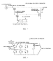
- Fig. 12 illustrates a conventional voltage adjusting apparatus.
- This apparatus is called a UPFC (Unified Power Flow Controller) and is capable not only of suppressing voltage fluctuation but also of controlling a power flow.
- a serial transformer T1 having a primary winding connected in series to a system between a power supply P and a load R and a parallel transformer T2 having a primary winding connected in parallel to the system are provided, and an AC terminal of an AC/DC converter I is connected to secondary windings of the transformers T1 and T2, respectively.
- DC terminals of the two AD/DC converters I are connected via a capacitor and have a so-called BTB (Back to Back) configuration.
- a compensation voltage is Vc
- a system voltage is Vs
- a system load capacity is Ps
- the AC/DC converter of the conventional voltage adjusting apparatus needs to have a capacity determined by the compensation voltage, the system line voltage, and the system load capacity.
- it leads to an increase in the output of the AC/DC converter and results in an increase in loss, size, complexity, and a cost of the voltage adjusting apparatus.
- Embodiments of the present invention are proposed in order to solve the above-described problems of the conventional technology and have an object to reduce an output of the AC/DC converter in a voltage adjusting apparatus connected in series to the system.
- a voltage adjusting apparatus which is an embodiment of the present invention, is proposed in order to achieve the above-described object and includes: a second serial transformer having a primary side connected in series to a secondary side of a first serial transformer having a primary side connected in series to a system and to a secondary side of a parallel transformer having a primary side connected in parallel to the system; and an AC/DC converter having an AC side connected to a secondary side of the second serial transformer.
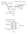
- a voltage adjusting apparatus 100 in this embodiment is an apparatus connected to a first serial transformer 13 and a parallel transformer 14 connected between a power supply 11 and a load 12 and has a second serial transformer 21 and a first AC/DC converter 22.
- the power supply 11 is a system power supply of a three-phase alternating current.
- a three-phase or single-phase commercial power supply at 50Hz or 60Hz is employed as the power supply 11.
- the load 12 is an apparatus installed in a consumer and consuming power from a system connected to the power supply 11.
- the first serial transformer 13 is a transformer connected in series to the system. That is, the first serial transformer 13 has a primary side connected in series between the power supply 11 and the load 12.
- the parallel transformer 14 is a transformer connected in parallel to the system. That is, the parallel transformer 14 has a primary side connected in parallel between the power supply 11 and the load 12.
- the second serial transformer 21 is a transformer having a primary side connected in series between a secondary side of the first serial transformer 13 and a secondary side of the parallel transformer 14.
- the first AC/DC converter 22 is an AC/DC converter having an AC terminal 22a connected to the secondary side of the second serial transformer 21.
- Fig. 2 illustrates a circuit configuration example of a three-phase AC/DC converter as the first AC/DC converter 22.
- the first AC/DC converter 22 has a switching element 22c, an antiparallel diode 22d and a capacitor 22e connected between the AC terminal 22a and a DC terminal 22b.
- the switching element 22c is a semiconductor device having self arc-extinguishing capability.
- an IGBT, a MOSFET, a GTO and the like can be used as the switching element 22c.
- the antiparallel diode 22d is a diode connected in parallel to the switching element 22c and returning an electric current of an inductor immediately after switching of a switch.
- the switching elements 22c are provided at least in a pair in each phase, and the AC terminal 22a is connected between the pair of switching elements 22c in each phase. An opposite end of the switching element 22c in each phase is connected to the DC terminal 22b.
- the capacitor 22e is an electric energy storage element connected in parallel to the DC terminal 22b.
- the capacitor 22e needs to maintain a certain charge, that is, electric energy in order to obtain an output of the first AC/DC converter 22.
- Methods for obtaining the energy for that purpose include a method of obtaining it from the system and a method of obtaining it from an outside, but the method is not limited to a specific one in this embodiment.
- the first AC/DC converter 22 switches the switching element 22c in accordance with an instruction value of a compensation voltage from a controller or the like and outputs voltage.
- the voltage output by the first AC/DC converter 22 may be Vc - Vtr.
- the output of the first AC/DC converter 22 can be reduced to a half of that of the conventional method.
- reduction in loss and size, simplification, and cost reduction of the voltage adjusting apparatus 100 can be made possible.
- the second serial transformer 21 is added to the conventional method.
- the power supply 11 at a high voltage and the second serial transformer 21 are insulated.
- a transformer with a relatively low withstanding voltage can be used as the second serial transformer 21, and a cost rise and a size increase can be suppressed.
- FIG. 3 A configuration of this embodiment will be described with reference to Figs. 3, 4 , and 5 .
- This embodiment has basically the same configuration as that of the above-described first embodiment.
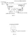
- a polarity reversing switch 30 is provided as illustrated in Fig. 3 .
- the polarity reversing switch 30 is a switch for reversing the polarity of the voltage between the terminals.
- the polarity reversing switch 30 is connected in series between the primary side of the second serial transformer 21 and the secondary side of the parallel transformer 14. This polarity reversing switch 30 is constituted by a semiconductor device.
- FIG. 4 illustrates a circuit configuration of one phase.
- AC switches (a) to (d) bridge-connected between an AC terminal (1) and an AC terminal (2) are provided.
- Each of the AC switches (a) to (d) has a pair of the switching element and the antiparallel diode connected in parallel so that a direction of the electric current becomes opposite.
- an IGBT is used as the switching element of the AC switches (a) to (d) as an example.
- any other self arc-extinguishing semiconductor devices can be also employed.
- the switching element can be also realized by an AC switch in which a thyristor is connected in an antiparallel manner and by any other types of semiconductor devices.
- FIG. 5 An example of a connection diagram of the polarity reversing switch 30 and the parallel transformer 14 is illustrated in Fig. 5 .
- a V-connection transformer with an open secondary side is used as the parallel transformer 14.
- two units of the polarity reversing switches 30 are connected to the secondary side of the parallel transformer 14.
- the output voltage of the parallel transformer 14 is +Vtr only.
- the output of the first AC/DC converter 22 can be reduced to a half of that of the conventional method.
- reduction in loss and size, simplification, and cost reduction of the voltage adjusting apparatus can be made possible.
- This embodiment will be described with reference to Fig. 6 .
- This embodiment has basically the same configuration as that of the above-described first embodiment.
- this embodiment is configured such that a DC terminal of a second AC/DC converter 23 is connected to the DC terminal 22b of the first AC/DC converter 22 via the capacitor 22e (see Fig. 2 ), which is a so-called BTB (Back to Back) configuration.
- an AC terminal of the second AC/DC converter 23 is connected in parallel to the secondary side of the parallel transformer 14.
- the polarity reversing switch 30 is provided similarly to the second embodiment, and the polarity reversing switch 30 is connected between the second AC/DC converter 23 and the parallel transformer 14.
- the polarity reversing switch 30 does not have to be provided as in the first embodiment.
- the first AC/DC converter 22 can freely output a voltage of an active component and a voltage of an reactive component.
- the parallel transformer 14 is a transformer having a third winding.
- the parallel transformer 14 has its secondary winding connected to the polarity reversing switch 30 and the third winding connected to the AC terminal of the second AC/DC converter 23.
- the polarity reversing switch 30 is made to function as a short-circuit switch.
- the AC terminal (1) can be short-circuited.
- the compensation voltage can be made 0 even if the output is 0.
- the second AC/DC converter 23 is connected to the third winding of the parallel transformer 14 and thus, energy can be acquired from the system.
- the polarity reversing switch 30 may be made to function as a short-circuit switch.
- Fig. 8 illustrates a relation between the compensation voltage Vc and the output Pc of the first AC/DC converter 22 in this embodiment in which a short-circuit state is made to occur and the embodiment in which a short-circuit state is not made to occur.
- a one-dot chain line indicates a conventional example
- a solid line indicates this embodiment
- a dotted line indicates an embodiment without short-circuit.
- FIG. 9 A configuration of this embodiment will be described with reference to Figs. 9 and 10 .
- This embodiment has basically the same configuration as that of the above-described first embodiment.
- an inter-phase short-circuit switch 31 is connected between the second serial transformer 21 and the parallel transformer 14.
- the parallel transformer 14 is a transformer having a third winding. Note that the parallel transformer 14 has its secondary winding connected to the short-circuit switch 31 and the third winding connected to the AC terminal of the second AC/DC converter 23.
- Fig. 10 illustrates the short-circuit switch 31 having an inter-phase AC switch 31a in a case of three-phase.
- the AC switch 31a include a mechanical switch, a self arc-extinguishing semiconductor device such as an IGBT, a bilateral semiconductor switch using a thyristor and the like.
- a short-circuit state can be generated by closing the AC switch 31a similarly to the fourth embodiment and thus, an output of the first AC/DC converter 22 can be reduced.
- This embodiment will be described with reference to Fig. 11 .
- This embodiment has basically the same configuration as that of the above-described first embodiment.
- an energy storage portion 22f is connected to the DC terminal 22b of the first AC/DC converter 22.
- Examples of the energy storage portion 22f include a battery and a storage apparatus of an electric double-layer capacitor (EDLC).
- EDLC electric double-layer capacitor
- the first AC/DC converter 22 can freely output a voltage of an effective component and a voltage of an ineffective component.
- this energy storage portion 22f may be configured to be charged or to store power from the system by being connected to the parallel transformer 14 via the second AC/DC converter 23 as in the above-described embodiment.
- the embodiment of the present invention is not limited to the above aspects.
- the primary side, the secondary side, and the third side of the above-described various transformers are merely numbered such that the side which is the closest to the system is the primary side for convenience so that each of the windings can be distinguished.
- the primary side, the secondary side, and the third side do not have to match the primary side, the secondary side, and the third side determined by rating of the transformer or the like.
Landscapes
- Engineering & Computer Science (AREA)
- Power Engineering (AREA)
- Rectifiers (AREA)
- Inverter Devices (AREA)
- Supply And Distribution Of Alternating Current (AREA)
- Ac-Ac Conversion (AREA)
- Direct Current Feeding And Distribution (AREA)
Applications Claiming Priority (1)
| Application Number | Priority Date | Filing Date | Title |
|---|---|---|---|
| JP2014102669A JP6363391B2 (ja) | 2014-05-16 | 2014-05-16 | 電圧調整装置 |
Publications (2)
| Publication Number | Publication Date |
|---|---|
| EP2945246A1 true EP2945246A1 (fr) | 2015-11-18 |
| EP2945246B1 EP2945246B1 (fr) | 2017-08-23 |
Family
ID=53054867
Family Applications (1)
| Application Number | Title | Priority Date | Filing Date |
|---|---|---|---|
| EP15165419.1A Not-in-force EP2945246B1 (fr) | 2014-05-16 | 2015-04-28 | Appareil de réglage de tension |
Country Status (6)
| Country | Link |
|---|---|
| US (1) | US9571002B2 (fr) |
| EP (1) | EP2945246B1 (fr) |
| JP (1) | JP6363391B2 (fr) |
| CN (1) | CN105098784B (fr) |
| AU (1) | AU2015202261B2 (fr) |
| ES (1) | ES2647312T3 (fr) |
Cited By (1)
| Publication number | Priority date | Publication date | Assignee | Title |
|---|---|---|---|---|
| US10710494B2 (en) | 2015-11-26 | 2020-07-14 | Johnson Electric International AG | Vehicular lighting assembly |
Families Citing this family (3)
| Publication number | Priority date | Publication date | Assignee | Title |
|---|---|---|---|---|
| CN105827118B (zh) * | 2016-04-17 | 2019-03-05 | 合肥博雷电气有限公司 | 一种开关电源高频变压器 |
| EP3783783A1 (fr) * | 2019-08-23 | 2021-02-24 | Siemens Energy Global GmbH & Co. KG | Agencement de régulation d'un flux de puissance dans un réseau à tension alternative et procédé de protection de l'agencement |
| CN111525570B (zh) * | 2020-07-06 | 2020-10-16 | 深圳华工能源技术有限公司 | 一种配用电系统智能节电装置及其控制方法 |
Citations (3)
| Publication number | Priority date | Publication date | Assignee | Title |
|---|---|---|---|---|
| DE19532177C1 (de) * | 1995-08-31 | 1997-01-16 | Siemens Ag | Steuerverfahren und Vorrichtung für einen stromrichtergesteuerten, stromeinprägenden Schrägtransformator |
| JP2003070251A (ja) | 2001-08-22 | 2003-03-07 | Toshiba Corp | 電圧調整装置 |
| US20060229767A1 (en) * | 2005-04-08 | 2006-10-12 | Chang Gung University | Method for calculating power flow solution of a power transmission network that includes unified power flow controllers |
Family Cites Families (15)
| Publication number | Priority date | Publication date | Assignee | Title |
|---|---|---|---|---|
| US5029285A (en) * | 1990-04-20 | 1991-07-02 | Albar, Inc. | Power back feed protection device |
| JPH04272208A (ja) | 1991-02-22 | 1992-09-29 | Asahi Chem Ind Co Ltd | 中空糸膜紡糸用紡口 |
| US5166597A (en) * | 1991-08-08 | 1992-11-24 | Electric Power Research Institute | Phase-shifting transformer system |
| EP0792483B1 (fr) * | 1994-07-22 | 2001-05-09 | Electric Power Research Institute, Inc | Regulateur d'une ligne de transmission comprenant une source de tension commandee en continu, sensible a une demande en puissance active ainsi qu'a une demande en puissance reactive |
| US5469044A (en) * | 1995-01-05 | 1995-11-21 | Westinghouse Electric Corporation | Transmission line power flow controller with unequal advancement and retardation of transmission angle |
| JP3406122B2 (ja) * | 1995-06-06 | 2003-05-12 | 愛知電機株式会社 | 配電線の電圧管理方式 |
| JP2000014009A (ja) * | 1998-06-24 | 2000-01-14 | Toshiba Corp | 電力系統安定化装置 |
| JP4672093B2 (ja) | 1998-07-14 | 2011-04-20 | 株式会社キューヘン | 電力品質補償装置 |
| US6900619B2 (en) * | 1999-11-24 | 2005-05-31 | American Superconductor Corporation | Reactive power compensation to minimize step voltage changes and transients |
| TWI291282B (en) * | 2002-06-03 | 2007-12-11 | Fuji Electric Co Ltd | Power converter |
| US7117070B2 (en) * | 2003-06-30 | 2006-10-03 | Rensselaer Polytechnic Institute | Power flow controller responsive to power circulation demand for optimizing power transfer |
| CN100364200C (zh) | 2004-02-12 | 2008-01-23 | 三菱电机株式会社 | 功率变换器 |
| CN100571003C (zh) * | 2005-06-01 | 2009-12-16 | 中国科学院电工研究所 | 一种不对称式电流调节器及其双极性控制方法 |
| US7813884B2 (en) * | 2008-01-14 | 2010-10-12 | Chang Gung University | Method of calculating power flow solution of a power grid that includes generalized power flow controllers |
| CN103703643B (zh) * | 2011-09-02 | 2017-12-19 | 株式会社日立制作所 | 系统电压稳定化装置以及稳定化方法 |
-
2014
- 2014-05-16 JP JP2014102669A patent/JP6363391B2/ja active Active
-
2015
- 2015-04-22 CN CN201510194551.0A patent/CN105098784B/zh not_active Expired - Fee Related
- 2015-04-28 EP EP15165419.1A patent/EP2945246B1/fr not_active Not-in-force
- 2015-04-28 ES ES15165419.1T patent/ES2647312T3/es active Active
- 2015-04-29 US US14/698,972 patent/US9571002B2/en active Active
- 2015-04-30 AU AU2015202261A patent/AU2015202261B2/en not_active Ceased
Patent Citations (3)
| Publication number | Priority date | Publication date | Assignee | Title |
|---|---|---|---|---|
| DE19532177C1 (de) * | 1995-08-31 | 1997-01-16 | Siemens Ag | Steuerverfahren und Vorrichtung für einen stromrichtergesteuerten, stromeinprägenden Schrägtransformator |
| JP2003070251A (ja) | 2001-08-22 | 2003-03-07 | Toshiba Corp | 電圧調整装置 |
| US20060229767A1 (en) * | 2005-04-08 | 2006-10-12 | Chang Gung University | Method for calculating power flow solution of a power transmission network that includes unified power flow controllers |
Cited By (1)
| Publication number | Priority date | Publication date | Assignee | Title |
|---|---|---|---|---|
| US10710494B2 (en) | 2015-11-26 | 2020-07-14 | Johnson Electric International AG | Vehicular lighting assembly |
Also Published As
| Publication number | Publication date |
|---|---|
| US20150333655A1 (en) | 2015-11-19 |
| CN105098784B (zh) | 2017-06-23 |
| CN105098784A (zh) | 2015-11-25 |
| US9571002B2 (en) | 2017-02-14 |
| AU2015202261B2 (en) | 2016-02-25 |
| EP2945246B1 (fr) | 2017-08-23 |
| JP6363391B2 (ja) | 2018-07-25 |
| AU2015202261A1 (en) | 2015-12-03 |
| JP2015220861A (ja) | 2015-12-07 |
| ES2647312T3 (es) | 2017-12-20 |
Similar Documents
| Publication | Publication Date | Title |
|---|---|---|
| Bhattacharya | Transforming the transformer | |
| JP5226873B2 (ja) | 太陽光発電用パワーコンディショナ | |
| US20210061114A1 (en) | On-board charging and discharging system | |
| US20120044728A1 (en) | Electric power converter | |
| US10186874B2 (en) | Predicting high-voltage direct current transmission in a wind turbine system | |
| US20080252142A1 (en) | Apparatus for Electrical Power Transmission | |
| US20080205093A1 (en) | Apparatus for Electrical Power Transmission | |
| US10243370B2 (en) | System and method for integrating energy storage into modular power converter | |
| US20180013291A1 (en) | Bidirectional dc-dc converter, power conditioner, and distributed power system | |
| EP3288169B1 (fr) | Dispositif de conversion de courant | |
| EP2945246B1 (fr) | Appareil de réglage de tension | |
| CN104218805A (zh) | 一种单双极性转换直流变换器 | |
| Liu et al. | Modular multilevel converter with high-frequency transformers for interfacing hybrid DC and AC microgrid systems | |
| RU159416U1 (ru) | Высоковольтный преобразователь частоты большой мощности | |
| RU2540966C1 (ru) | Статический преобразователь | |
| US20150249400A1 (en) | Converter | |
| Koyama et al. | System fault test of SiC device applied 6.6 kV transformerless D-STATCOM | |
| US20240055973A1 (en) | Power Supply Device | |
| EP3961847A1 (fr) | Dispositif d'alimentation électrique | |
| RU151864U1 (ru) | Система электроснабжения собственных нужд электростанции | |
| RU2481691C1 (ru) | Статический преобразователь | |
| RU2661936C1 (ru) | Система электроснабжения потребителей собственных нужд электрической станции | |
| RU2619917C1 (ru) | Устройство гарантированного электропитания | |
| Srivastava et al. | Harmonic compensation of HVDC rectifier using shunt active filter | |
| RU124067U1 (ru) | Установка для плавки гололеда и компенсации реактивной мощности |
Legal Events
| Date | Code | Title | Description |
|---|---|---|---|
| PUAI | Public reference made under article 153(3) epc to a published international application that has entered the european phase |
Free format text: ORIGINAL CODE: 0009012 |
|
| AK | Designated contracting states |
Kind code of ref document: A1 Designated state(s): AL AT BE BG CH CY CZ DE DK EE ES FI FR GB GR HR HU IE IS IT LI LT LU LV MC MK MT NL NO PL PT RO RS SE SI SK SM TR |
|
| AX | Request for extension of the european patent |
Extension state: BA ME |
|
| 17P | Request for examination filed |
Effective date: 20160408 |
|
| RBV | Designated contracting states (corrected) |
Designated state(s): AL AT BE BG CH CY CZ DE DK EE ES FI FR GB GR HR HU IE IS IT LI LT LU LV MC MK MT NL NO PL PT RO RS SE SI SK SM TR |
|
| RIC1 | Information provided on ipc code assigned before grant |
Ipc: H02J 3/18 20060101AFI20170208BHEP |
|
| GRAP | Despatch of communication of intention to grant a patent |
Free format text: ORIGINAL CODE: EPIDOSNIGR1 |
|
| INTG | Intention to grant announced |
Effective date: 20170317 |
|
| GRAS | Grant fee paid |
Free format text: ORIGINAL CODE: EPIDOSNIGR3 |
|
| GRAA | (expected) grant |
Free format text: ORIGINAL CODE: 0009210 |
|
| AK | Designated contracting states |
Kind code of ref document: B1 Designated state(s): AL AT BE BG CH CY CZ DE DK EE ES FI FR GB GR HR HU IE IS IT LI LT LU LV MC MK MT NL NO PL PT RO RS SE SI SK SM TR |
|
| REG | Reference to a national code |
Ref country code: GB Ref legal event code: FG4D |
|
| REG | Reference to a national code |
Ref country code: CH Ref legal event code: EP |
|
| REG | Reference to a national code |
Ref country code: AT Ref legal event code: REF Ref document number: 922290 Country of ref document: AT Kind code of ref document: T Effective date: 20170915 |
|
| REG | Reference to a national code |
Ref country code: IE Ref legal event code: FG4D |
|
| REG | Reference to a national code |
Ref country code: DE Ref legal event code: R096 Ref document number: 602015004223 Country of ref document: DE |
|
| REG | Reference to a national code |
Ref country code: ES Ref legal event code: FG2A Ref document number: 2647312 Country of ref document: ES Kind code of ref document: T3 Effective date: 20171220 |
|
| REG | Reference to a national code |
Ref country code: NL Ref legal event code: MP Effective date: 20170823 |
|
| REG | Reference to a national code |
Ref country code: LT Ref legal event code: MG4D |
|
| REG | Reference to a national code |
Ref country code: AT Ref legal event code: MK05 Ref document number: 922290 Country of ref document: AT Kind code of ref document: T Effective date: 20170823 |
|
| PG25 | Lapsed in a contracting state [announced via postgrant information from national office to epo] |
Ref country code: LT Free format text: LAPSE BECAUSE OF FAILURE TO SUBMIT A TRANSLATION OF THE DESCRIPTION OR TO PAY THE FEE WITHIN THE PRESCRIBED TIME-LIMIT Effective date: 20170823 Ref country code: NO Free format text: LAPSE BECAUSE OF FAILURE TO SUBMIT A TRANSLATION OF THE DESCRIPTION OR TO PAY THE FEE WITHIN THE PRESCRIBED TIME-LIMIT Effective date: 20171123 Ref country code: NL Free format text: LAPSE BECAUSE OF FAILURE TO SUBMIT A TRANSLATION OF THE DESCRIPTION OR TO PAY THE FEE WITHIN THE PRESCRIBED TIME-LIMIT Effective date: 20170823 Ref country code: FI Free format text: LAPSE BECAUSE OF FAILURE TO SUBMIT A TRANSLATION OF THE DESCRIPTION OR TO PAY THE FEE WITHIN THE PRESCRIBED TIME-LIMIT Effective date: 20170823 Ref country code: SE Free format text: LAPSE BECAUSE OF FAILURE TO SUBMIT A TRANSLATION OF THE DESCRIPTION OR TO PAY THE FEE WITHIN THE PRESCRIBED TIME-LIMIT Effective date: 20170823 Ref country code: HR Free format text: LAPSE BECAUSE OF FAILURE TO SUBMIT A TRANSLATION OF THE DESCRIPTION OR TO PAY THE FEE WITHIN THE PRESCRIBED TIME-LIMIT Effective date: 20170823 Ref country code: AT Free format text: LAPSE BECAUSE OF FAILURE TO SUBMIT A TRANSLATION OF THE DESCRIPTION OR TO PAY THE FEE WITHIN THE PRESCRIBED TIME-LIMIT Effective date: 20170823 |
|
| PG25 | Lapsed in a contracting state [announced via postgrant information from national office to epo] |
Ref country code: GR Free format text: LAPSE BECAUSE OF FAILURE TO SUBMIT A TRANSLATION OF THE DESCRIPTION OR TO PAY THE FEE WITHIN THE PRESCRIBED TIME-LIMIT Effective date: 20171124 Ref country code: RS Free format text: LAPSE BECAUSE OF FAILURE TO SUBMIT A TRANSLATION OF THE DESCRIPTION OR TO PAY THE FEE WITHIN THE PRESCRIBED TIME-LIMIT Effective date: 20170823 Ref country code: IS Free format text: LAPSE BECAUSE OF FAILURE TO SUBMIT A TRANSLATION OF THE DESCRIPTION OR TO PAY THE FEE WITHIN THE PRESCRIBED TIME-LIMIT Effective date: 20171223 Ref country code: BG Free format text: LAPSE BECAUSE OF FAILURE TO SUBMIT A TRANSLATION OF THE DESCRIPTION OR TO PAY THE FEE WITHIN THE PRESCRIBED TIME-LIMIT Effective date: 20171123 Ref country code: PL Free format text: LAPSE BECAUSE OF FAILURE TO SUBMIT A TRANSLATION OF THE DESCRIPTION OR TO PAY THE FEE WITHIN THE PRESCRIBED TIME-LIMIT Effective date: 20170823 Ref country code: LV Free format text: LAPSE BECAUSE OF FAILURE TO SUBMIT A TRANSLATION OF THE DESCRIPTION OR TO PAY THE FEE WITHIN THE PRESCRIBED TIME-LIMIT Effective date: 20170823 |
|
| PG25 | Lapsed in a contracting state [announced via postgrant information from national office to epo] |
Ref country code: DK Free format text: LAPSE BECAUSE OF FAILURE TO SUBMIT A TRANSLATION OF THE DESCRIPTION OR TO PAY THE FEE WITHIN THE PRESCRIBED TIME-LIMIT Effective date: 20170823 Ref country code: RO Free format text: LAPSE BECAUSE OF FAILURE TO SUBMIT A TRANSLATION OF THE DESCRIPTION OR TO PAY THE FEE WITHIN THE PRESCRIBED TIME-LIMIT Effective date: 20170823 Ref country code: CZ Free format text: LAPSE BECAUSE OF FAILURE TO SUBMIT A TRANSLATION OF THE DESCRIPTION OR TO PAY THE FEE WITHIN THE PRESCRIBED TIME-LIMIT Effective date: 20170823 |
|
| REG | Reference to a national code |
Ref country code: DE Ref legal event code: R097 Ref document number: 602015004223 Country of ref document: DE |
|
| PG25 | Lapsed in a contracting state [announced via postgrant information from national office to epo] |
Ref country code: SK Free format text: LAPSE BECAUSE OF FAILURE TO SUBMIT A TRANSLATION OF THE DESCRIPTION OR TO PAY THE FEE WITHIN THE PRESCRIBED TIME-LIMIT Effective date: 20170823 Ref country code: EE Free format text: LAPSE BECAUSE OF FAILURE TO SUBMIT A TRANSLATION OF THE DESCRIPTION OR TO PAY THE FEE WITHIN THE PRESCRIBED TIME-LIMIT Effective date: 20170823 Ref country code: SM Free format text: LAPSE BECAUSE OF FAILURE TO SUBMIT A TRANSLATION OF THE DESCRIPTION OR TO PAY THE FEE WITHIN THE PRESCRIBED TIME-LIMIT Effective date: 20170823 |
|
| PLBE | No opposition filed within time limit |
Free format text: ORIGINAL CODE: 0009261 |
|
| STAA | Information on the status of an ep patent application or granted ep patent |
Free format text: STATUS: NO OPPOSITION FILED WITHIN TIME LIMIT |
|
| 26N | No opposition filed |
Effective date: 20180524 |
|
| PG25 | Lapsed in a contracting state [announced via postgrant information from national office to epo] |
Ref country code: SI Free format text: LAPSE BECAUSE OF FAILURE TO SUBMIT A TRANSLATION OF THE DESCRIPTION OR TO PAY THE FEE WITHIN THE PRESCRIBED TIME-LIMIT Effective date: 20170823 |
|
| PG25 | Lapsed in a contracting state [announced via postgrant information from national office to epo] |
Ref country code: MC Free format text: LAPSE BECAUSE OF FAILURE TO SUBMIT A TRANSLATION OF THE DESCRIPTION OR TO PAY THE FEE WITHIN THE PRESCRIBED TIME-LIMIT Effective date: 20170823 |
|
| REG | Reference to a national code |
Ref country code: CH Ref legal event code: PL |
|
| REG | Reference to a national code |
Ref country code: BE Ref legal event code: MM Effective date: 20180430 |
|
| REG | Reference to a national code |
Ref country code: IE Ref legal event code: MM4A |
|
| PG25 | Lapsed in a contracting state [announced via postgrant information from national office to epo] |
Ref country code: LU Free format text: LAPSE BECAUSE OF NON-PAYMENT OF DUE FEES Effective date: 20180428 |
|
| PG25 | Lapsed in a contracting state [announced via postgrant information from national office to epo] |
Ref country code: BE Free format text: LAPSE BECAUSE OF NON-PAYMENT OF DUE FEES Effective date: 20180430 Ref country code: CH Free format text: LAPSE BECAUSE OF NON-PAYMENT OF DUE FEES Effective date: 20180430 Ref country code: LI Free format text: LAPSE BECAUSE OF NON-PAYMENT OF DUE FEES Effective date: 20180430 |
|
| PG25 | Lapsed in a contracting state [announced via postgrant information from national office to epo] |
Ref country code: FR Free format text: LAPSE BECAUSE OF NON-PAYMENT OF DUE FEES Effective date: 20180430 Ref country code: IE Free format text: LAPSE BECAUSE OF NON-PAYMENT OF DUE FEES Effective date: 20180428 |
|
| PG25 | Lapsed in a contracting state [announced via postgrant information from national office to epo] |
Ref country code: MT Free format text: LAPSE BECAUSE OF NON-PAYMENT OF DUE FEES Effective date: 20180428 |
|
| PG25 | Lapsed in a contracting state [announced via postgrant information from national office to epo] |
Ref country code: TR Free format text: LAPSE BECAUSE OF FAILURE TO SUBMIT A TRANSLATION OF THE DESCRIPTION OR TO PAY THE FEE WITHIN THE PRESCRIBED TIME-LIMIT Effective date: 20170823 |
|
| PG25 | Lapsed in a contracting state [announced via postgrant information from national office to epo] |
Ref country code: PT Free format text: LAPSE BECAUSE OF FAILURE TO SUBMIT A TRANSLATION OF THE DESCRIPTION OR TO PAY THE FEE WITHIN THE PRESCRIBED TIME-LIMIT Effective date: 20170823 |
|
| PG25 | Lapsed in a contracting state [announced via postgrant information from national office to epo] |
Ref country code: CY Free format text: LAPSE BECAUSE OF FAILURE TO SUBMIT A TRANSLATION OF THE DESCRIPTION OR TO PAY THE FEE WITHIN THE PRESCRIBED TIME-LIMIT Effective date: 20170823 Ref country code: HU Free format text: LAPSE BECAUSE OF FAILURE TO SUBMIT A TRANSLATION OF THE DESCRIPTION OR TO PAY THE FEE WITHIN THE PRESCRIBED TIME-LIMIT; INVALID AB INITIO Effective date: 20150428 Ref country code: MK Free format text: LAPSE BECAUSE OF NON-PAYMENT OF DUE FEES Effective date: 20170823 |
|
| PG25 | Lapsed in a contracting state [announced via postgrant information from national office to epo] |
Ref country code: AL Free format text: LAPSE BECAUSE OF FAILURE TO SUBMIT A TRANSLATION OF THE DESCRIPTION OR TO PAY THE FEE WITHIN THE PRESCRIBED TIME-LIMIT Effective date: 20170823 |
|
| PGFP | Annual fee paid to national office [announced via postgrant information from national office to epo] |
Ref country code: DE Payment date: 20200415 Year of fee payment: 6 Ref country code: ES Payment date: 20200504 Year of fee payment: 6 |
|
| PGFP | Annual fee paid to national office [announced via postgrant information from national office to epo] |
Ref country code: GB Payment date: 20200416 Year of fee payment: 6 Ref country code: IT Payment date: 20200312 Year of fee payment: 6 |
|
| REG | Reference to a national code |
Ref country code: DE Ref legal event code: R119 Ref document number: 602015004223 Country of ref document: DE |
|
| GBPC | Gb: european patent ceased through non-payment of renewal fee |
Effective date: 20210428 |
|
| PG25 | Lapsed in a contracting state [announced via postgrant information from national office to epo] |
Ref country code: DE Free format text: LAPSE BECAUSE OF NON-PAYMENT OF DUE FEES Effective date: 20211103 Ref country code: GB Free format text: LAPSE BECAUSE OF NON-PAYMENT OF DUE FEES Effective date: 20210428 |
|
| REG | Reference to a national code |
Ref country code: ES Ref legal event code: FD2A Effective date: 20220706 |
|
| PG25 | Lapsed in a contracting state [announced via postgrant information from national office to epo] |
Ref country code: ES Free format text: LAPSE BECAUSE OF NON-PAYMENT OF DUE FEES Effective date: 20210429 |
|
| PG25 | Lapsed in a contracting state [announced via postgrant information from national office to epo] |
Ref country code: IT Free format text: LAPSE BECAUSE OF NON-PAYMENT OF DUE FEES Effective date: 20200428 |