EP2944932B1 - Verfahren zur messung der temperatur einer stromspeichervorrichtung - Google Patents
Verfahren zur messung der temperatur einer stromspeichervorrichtung Download PDFInfo
- Publication number
- EP2944932B1 EP2944932B1 EP13870565.2A EP13870565A EP2944932B1 EP 2944932 B1 EP2944932 B1 EP 2944932B1 EP 13870565 A EP13870565 A EP 13870565A EP 2944932 B1 EP2944932 B1 EP 2944932B1
- Authority
- EP
- European Patent Office
- Prior art keywords
- electrical storage
- storage device
- temperature
- internal
- alternating
- Prior art date
- Legal status (The legal status is an assumption and is not a legal conclusion. Google has not performed a legal analysis and makes no representation as to the accuracy of the status listed.)
- Not-in-force
Links
Images


Classifications
-
- G—PHYSICS
- G01—MEASURING; TESTING
- G01K—MEASURING TEMPERATURE; MEASURING QUANTITY OF HEAT; THERMALLY-SENSITIVE ELEMENTS NOT OTHERWISE PROVIDED FOR
- G01K13/00—Thermometers specially adapted for specific purposes
-
- G—PHYSICS
- G01—MEASURING; TESTING
- G01K—MEASURING TEMPERATURE; MEASURING QUANTITY OF HEAT; THERMALLY-SENSITIVE ELEMENTS NOT OTHERWISE PROVIDED FOR
- G01K7/00—Measuring temperature based on the use of electric or magnetic elements directly sensitive to heat ; Power supply therefor, e.g. using thermoelectric elements
-
- G—PHYSICS
- G01—MEASURING; TESTING
- G01R—MEASURING ELECTRIC VARIABLES; MEASURING MAGNETIC VARIABLES
- G01R31/00—Arrangements for testing electric properties; Arrangements for locating electric faults; Arrangements for electrical testing characterised by what is being tested not provided for elsewhere
- G01R31/36—Arrangements for testing, measuring or monitoring the electrical condition of accumulators or electric batteries, e.g. capacity or state of charge [SoC]
- G01R31/382—Arrangements for monitoring battery or accumulator variables, e.g. SoC
-
- G—PHYSICS
- G01—MEASURING; TESTING
- G01R—MEASURING ELECTRIC VARIABLES; MEASURING MAGNETIC VARIABLES
- G01R31/00—Arrangements for testing electric properties; Arrangements for locating electric faults; Arrangements for electrical testing characterised by what is being tested not provided for elsewhere
- G01R31/36—Arrangements for testing, measuring or monitoring the electrical condition of accumulators or electric batteries, e.g. capacity or state of charge [SoC]
- G01R31/389—Measuring internal impedance, internal conductance or related variables
-
- H—ELECTRICITY
- H01—ELECTRIC ELEMENTS
- H01M—PROCESSES OR MEANS, e.g. BATTERIES, FOR THE DIRECT CONVERSION OF CHEMICAL ENERGY INTO ELECTRICAL ENERGY
- H01M10/00—Secondary cells; Manufacture thereof
- H01M10/42—Methods or arrangements for servicing or maintenance of secondary cells or secondary half-cells
- H01M10/48—Accumulators combined with arrangements for measuring, testing or indicating the condition of cells, e.g. the level or density of the electrolyte
- H01M10/486—Accumulators combined with arrangements for measuring, testing or indicating the condition of cells, e.g. the level or density of the electrolyte for measuring temperature
-
- Y—GENERAL TAGGING OF NEW TECHNOLOGICAL DEVELOPMENTS; GENERAL TAGGING OF CROSS-SECTIONAL TECHNOLOGIES SPANNING OVER SEVERAL SECTIONS OF THE IPC; TECHNICAL SUBJECTS COVERED BY FORMER USPC CROSS-REFERENCE ART COLLECTIONS [XRACs] AND DIGESTS
- Y02—TECHNOLOGIES OR APPLICATIONS FOR MITIGATION OR ADAPTATION AGAINST CLIMATE CHANGE
- Y02E—REDUCTION OF GREENHOUSE GAS [GHG] EMISSIONS, RELATED TO ENERGY GENERATION, TRANSMISSION OR DISTRIBUTION
- Y02E60/00—Enabling technologies; Technologies with a potential or indirect contribution to GHG emissions mitigation
- Y02E60/10—Energy storage using batteries
Definitions
- the present invention relates to a method of measuring the temperature of an electrical storage device and particularly to an electrical storage device temperature-measuring method for accurately measuring the internal temperature of the electrical storage device.
- Electrical storage devices such as a lithium-ion secondary battery and an electric double-layer capacitor have been used for various purposes and have been widely applied to, for example, battery packs for mobile phones, batteries for PCs, and batteries for vehicles.
- detection of a state of an electrical storage device such as a deterioration state (referred to as SOH; state of health) and a remaining capacity (referred to as SOC; state of charge) is a very important matter.
- SOH deterioration state
- SOC state of charge
- detection of the state of an electrical storage device in a vehicle such as an energy-saving vehicle or a hybrid vehicle, which has a start-stop system, or in an electric vehicle is strongly associated with vehicle travelling and is therefore drawing attention as being very important.
- the voltage, the current, and the temperature of the electrical storage device are measured, and the deterioration state (SOH), the remaining capacity (SOC), or the like of the electrical storage device is measured on the basis of the measurement result.
- SOH deterioration state
- SOC remaining capacity
- the temperature of the electrical storage device is an important measurement parameter since temperature has a great influence on deterioration of the electrical storage device.
- a method is generally known in which a temperature detection element is in contact with or connected to the electrical storage device to directly measure the temperature (see, for example, PTL 1).
- a Zener diode is used as a temperature detection element and connected to the positive terminal of the electrical storage device, such that the heat transmitted from the positive terminal of the electrical storage device can be accurately measured.
- the measurement method of PTL 1 has a problem in that, due to self-heating or the like of an internal resistor of the electrical storage device, a great difference may occur between the temperature of a temperature detection point of the temperature detection element (the positive terminal of the electrical storage device in Known Example 1) and the internal temperature of the electrical storage device, and thus it is difficult to accurately determine the temperature of the electrical storage device.
- a characteristics map representing the relationship of the internal resistance (internal impedance), the remaining capacity (SOC), and the temperature of an electrical storage device is obtained in advance, and the temperature of the electrical storage device is determined by applying, to the characteristics map, the remaining capacity (SOC) and the internal resistance (internal impedance) measured during temperature detection (see, for example, PTL 2).
- the remaining capacity (SOC) of the electrical storage device is independently calculated by adding up the values of the currents flowing through the electrical storage device. After the addition, the temperature of the electrical storage device is obtained on the basis of the calculated remaining capacity (SOC) and the internal resistance defined in the above-described characteristics map. This leads to a problem of complex processing being required for obtaining the temperature of the electrical storage device.
- the present invention has been made in view of the above-described respects and aims to provide a method for measuring the temperature of an electrical storage device, the method enabling accurate measurement of the internal temperature of the electrical storage device without the need for complex computational processing.
- An electrical storage device temperature-measuring method includes: measuring a real part of internal impedance of an electrical storage device by using an alternating-current signal having a frequency band in which the real part of the internal impedance of the electrical storage device does not change according to a remaining capacity (SOC: state of charge) of the electrical storage device; and calculating internal temperature of the electrical storage device from a measured value of the real part of the internal impedance.
- SOC remaining capacity
- the real part of the internal impedance of the electrical storage device is measured by using an alternating-current signal having a frequency band in which the real part of the internal impedance of the electrical storage device does not change.
- This makes it possible to measure the real part of the internal impedance of the electrical storage device, which is likely to depend only on the internal temperature of the electrical storage device, such that the internal temperature of the electrical storage device can be accurately measured.
- the real part of the internal impedance of the electrical storage device is measured by using an alternating-current signal having a frequency at which the real part of the internal impedance of the electrical storage device does not change, the remaining capacity of the electrical storage device does not need to be calculated independently. For this reason, the internal temperature of the electrical storage device can be accurately measured without the need for complex computational processing.
- the real part of the internal impedance of the electrical storage device is measured by using an alternating-current signal having a frequency band between 100 KHz and 1 MHz inclusive, and the internal temperature of the electrical storage device is calculated from a measured value of the real part of the internal impedance.
- the real part of the internal impedance of the electrical storage device is measured by using an alternating-current signal having a frequency of 300 KHz, and the internal temperature of the electrical storage device is calculated from a measured value of the real part of the internal impedance.
- the electrical storage device temperature-measuring method of the present invention includes: measuring internal impedance of an electrical storage device by using an alternating-current signal having a frequency band in which the internal impedance of the electrical storage device does not change according to a remaining capacity (SOC: state of charge) of the electrical storage device; and calculating internal temperature of the electrical storage device from a measured value of the internal impedance.
- SOC remaining capacity
- the internal impedance of the electrical storage device is measured by using an alternating-current signal having a frequency band in which the internal impedance of the electrical storage device does not change.
- This makes it possible to measure the internal impedance of the electrical storage device, which is likely to depend only on the internal temperature of the electrical storage device, such that the internal temperature of the electrical storage device can be accurately measured.
- the internal impedance of the electrical storage device is measured by using an alternating-current signal having a frequency at which the internal impedance of the electrical storage device does not change, the remaining capacity of the electrical storage device does not need to be calculated independently. For this reason, the internal temperature of the electrical storage device can be accurately measured without the need for complex computational processing.
- the internal impedance of the electrical storage device is measured by using an alternating-current signal having a frequency band between 10 KHz and 100 KHz inclusive, and the internal temperature of the electrical storage device is calculated from a measured value of the internal impedance.
- the internal impedance of the electrical storage device is measured by using an alternating-current signal having a frequency of 30 KHz, and the internal temperature of the electrical storage device is calculated from a measured value of the internal impedance.
- the alternating-current signal is superimposed on a direct current to be used for charging or discharging the electrical storage device.
- an alternating-current signal to be used for measuring the internal temperature of the electrical storage device is superimposed on a direct current to be used for charging or discharging the electrical storage device.
- the electrical storage device includes a current detection unit and a voltage detection unit for detecting the alternating-current signal, and at least one of the current detection unit and the voltage detection unit is used for calculation of the remaining capacity of the electrical storage device.
- at least one of the current detection unit and the voltage detection unit for detecting an alternating-current signal to be used for measuring the internal temperature of the electrical storage device is used to calculate the remaining capacity of the electrical storage device.
- the component (the current detection unit or the voltage detection unit) to be used for calculation of the remaining capacity of the electrical storage device is also used for the measurement of the internal temperature of the electrical storage device. This makes it possible to accurately measure the internal temperature of the electrical storage device with a reduced number of components for measuring the internal temperature of the electrical storage device.
- the current detection unit which is a single one, is connected to the plurality of electrical storage devices in series and the voltage detection unit is provided for each of the electrical storage devices.
- the single current detection unit is connected to the plurality of serially connected electrical storage devices. Accordingly, the current detection unit can be used for all of the plurality of electrical storage devices. This makes it possible to accurately measure the internal temperatures of the electrical storage devices with a reduced number of components for measuring the internal temperatures of the electrical storage devices.
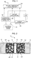
- Fig. 1 is a schematic diagram illustrating an example of a configuration of a measuring system to which an electrical storage device temperature-measuring method according to an embodiment of the present invention is applied.
- Fig. 2 is a schematic diagram of a configuration of a lithium-ion secondary battery forming an electrical storage device of the measuring system according to the embodiment.
- the electrical storage device temperature-measuring method according to this embodiment is a method performed by using, for example, a measuring system 100 for measuring the internal temperature of an electrical storage device 101 illustrated in Fig. 1 .
- the measuring system 100 includes an alternating-current signal source unit 102 for providing an alternating-current signal in a predetermined frequency band to the electrical storage device 101, a current detection unit 103 and a voltage detection unit 104 for detecting a current and a voltage responding to the alternating-current signal in the predetermined frequency band, and an internal-temperature calculation unit 105 for calculating the internal temperature of the electrical storage device 101 by using the alternating-current signal in the predetermined frequency band as well as the detected current and voltage.
- an alternating-current signal source unit 102 for providing an alternating-current signal in a predetermined frequency band to the electrical storage device 101
- a current detection unit 103 and a voltage detection unit 104 for detecting a current and a voltage responding to the alternating-current signal in the predetermined frequency band
- an internal-temperature calculation unit 105 for calculating the internal temperature of the electrical storage device 101 by using the alternating-current signal in the predetermined frequency band as well as the detected current and voltage.
- the electrical storage device 101 is, for example, a rechargeable chemical battery such as a lithium-ion secondary battery and also includes a device that can store electrical energy by using ions, such as an electric double-layer capacitor.
- the electrical storage device 101 mainly includes a positive electrode collector A1, a negative electrode collector C1, an electrolyte E1, and a separator S1.
- the electrical storage device 101 includes, in addition to the above components, a positive-electrode active material A51, which is a material for storing electricity on the positive electrode collector A1 side, a negative-electrode active material C51, which is a material for storing electricity on the negative electrode collector C1 side, an electrical conduction assistant D51, which is added in order to make electricity flow easily, and a binding agent, which is a binder, as illustrated in Fig. 2 .
- a positive-electrode active material A51 which is a material for storing electricity on the positive electrode collector A1 side
- a negative-electrode active material C51 which is a material for storing electricity on the negative electrode collector C1 side
- an electrical conduction assistant D51 which is added in order to make electricity flow easily
- a binding agent which is a binder, as illustrated in Fig. 2 .
- the lithium-ion secondary battery L1 mainly aluminum (Al) is used as the positive electrode collector A1
- mainly copper (Cu) is used as the negative electrode collector C1
- mainly a solution composed of an organic solvent (e.g., C4H6O3) and a lithium salt (e.g., LiPF6) is used as the electrolyte E1
- mainly lithium cobalt oxide (LiCoO2) is used as the positive-electrode active material A51
- mainly carbon (C) is used as the negative-electrode active material C51.
- the positive-electrode active material A51 may be composed of nickel lithium oxide (LiNiO2), lithium manganese oxide (LiMn2O4), or olivine-type lithium phosphate (LiFePO4).
- the carbon (C) of the negative-electrode active material C51 layered black lead crystal is used and is characterized by lithium being stored in an ionic state between the layers.
- the negative-electrode active material C51 may be composed of lithium titanate (Li4Ti5O12) silicon monoxide (SiO), an alloy of Sn, or an alloy of Si.
- the alternating-current signal source unit 102 serves to generate an alternating-current signal having a frequency band in which the real part of the internal impedance of the electrical storage device 101 does not change according to the remaining capacity (SOC: state of charge) of the electrical storage device 101.
- the alternating-current signal source unit 102 generates an alternating-current signal in the frequency band between 100 KHz and 1 MHz inclusive, for example. More preferably, the alternating-current signal source unit 102 generates an alternating-current signal having a frequency of 300 KHz. Note that a description is given later of the frequency band of the alternating-current signal generated by the alternating-current signal source unit 102.
- the current detection unit 103 is connected in a circuit to which the electrical storage device 101 is connected and a load 106 is applied.
- the current detection unit 103 mainly includes a current sensor for detecting a current and a control circuit for the current sensor and detects a current flowing through the circuit.
- a current sensor for example, a small-size current sensor using a magnetoresistive element can be used.
- the voltage detection unit 104 mainly includes a voltage sensor for detecting a voltage and a control circuit for the voltage sensor, and detects the voltage of the electrical storage device 101.
- the internal-temperature calculation unit 105 measures the real part of the internal impedance (internal resistance) of the electrical storage device 101 by using the alternating-current signal in the predetermined frequency band received from the alternating-current signal source unit 102, and the current and voltage detected by the current detection unit 103 and the voltage detection unit 104.
- the internal-temperature calculation unit 105 calculates the internal temperature of the electrical storage device 101 from the measured value of the real part of the internal impedance.
- the load 106 includes a power converter such as an inverter for converting a direct-current power from the electrical storage device 101 into an alternating-current power or a converter such as a DC-DC converter, for example.
- the internal temperature and the remaining capacity (SOC) of the electrical storage device 101 greatly affect the internal impedance of the electrical storage device 101.
- SOC remaining capacity
- Fig. 3 is an example of a graph presenting the temperature dependence of the real part of the internal impedance of the electrical storage device 101 in the measuring system 100 according to this embodiment.
- Fig. 4 is an example of a graph presenting the SOC dependence of the real part of the internal impedance of the electrical storage device 101 in the measuring system 100 according to this embodiment.
- the frequency of an alternating-current signal provided to the electrical storage device 101 is plotted on the horizontal axis
- the internal resistance of the electrical storage device 101 is plotted on the vertical axis.
- Fig. 3 presents the coefficient indicating the influence of the internal temperature on the internal resistance of the electrical storage device 101 (temperature coefficient).
- the temperature coefficient indicates that the internal resistance increases as the temperature increases in the case of an alternating-current signal in the frequency band between 10 KHz and 3 MHz inclusive (band a shown in Fig. 3 ) and that the internal resistance decreases as the temperature increases in the case of an alternating-current signal in the frequency band excluding the above (in the frequency band lower than 10 KHz (band b shown in Fig. 3 ) and the frequency band higher than 3 MHz (band c shown in Fig. 3 )).
- the temperature dependence is positive in the former frequency band whereas the temperature dependence is negative in the latter frequency band.
- Fig. 4 presents the coefficient indicating the influence of the SOC on the internal resistance of the electrical storage device 101 (SOC coefficient).
- the SOC coefficient indicates that the internal resistance increases as the SOC increases regarding an alternating-current signal in the frequency band lower than 300 KHz (band a shown in Fig. 4 ) and that the internal resistance decreases as the SOC increases regarding an alternating-current signal in the frequency band higher than 300 KHz (band b shown in Fig. 4 ).
- the SOC dependence is positive in the former frequency band whereas the SOC dependence is negative in the latter frequency band.
- the SOC dependence switches from positive dependence to negative dependence in alternating-current signals each having a frequency of around 300 KHz.
- an alternating-current signal having a frequency of around 300 KHz is close to the state of having no SOC influence on the internal resistance of the electrical storage device 101.
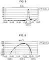
- Fig. 5 is an example of a graph presenting the influence of the internal temperature and the remaining capacity (SOC) of the electrical storage device 101 on the real part of the internal impedance of the electrical storage device 101 in the measuring system 100 according to this embodiment.
- the frequency of an alternating-current signal provided to the electrical storage device 101 is plotted on the horizontal axis, and the value obtained by dividing the influence of the internal temperature of the electrical storage device 101 by the influence of the SOC of the electrical storage device 101 (internal temperature / SOC) is plotted on the vertical axis.
- Fig. 5 presents the coefficient indicating the influence of the internal temperature and the remaining capacity (SOC) on the internal resistance of the electrical storage device 101 (temperature/SOC coefficient).
- the temperature/SOC coefficient has a large value in the case of an alternating-current signal in the frequency band between 100 KHz and 1 MHz inclusive (band a shown in Fig. 5 ) compared with one in the frequency band excluding the above and has the largest value in the case of an alternating-current signal having a frequency of 300 KHz. This is because, as shown in Fig. 4 , an alternating-current signal having a frequency of around 300 KHz is close to the state of having no SOC influence on the internal resistance of the electrical storage device 101.
- such an alternating-current signal having a frequency band in which the alternating-current signal is close to a state of having no SOC influence on the internal resistance of the electrical storage device 101 is defined as an alternating-current signal in a frequency band in which the real part of the internal impedance of the electrical storage device 101 does not change according to the SOC of the electrical storage device 101.
- the real part of the internal impedance of the electrical storage device 101 is measured by using an alternating-current signal in such a frequency band, and the internal temperature of the electrical storage device 101 is calculated from the measured value of the real part of the internal impedance.
- the real part of the internal impedance of the electrical storage device 101 is measured by using an alternating-current signal having a frequency band in which the real part of the internal impedance of the electrical storage device 101 does not change. This makes it possible to measure the real part of the internal impedance of the electrical storage device 101, which is likely to depend only on the internal temperature of the electrical storage device 101, such that the internal temperature of the electrical storage device 101 can be accurately measured.
- the real part of the internal impedance of the electrical storage device 101 is measured by using an alternating-current signal having a frequency at which the real part of the internal impedance of the electrical storage device 101 does not change, the remaining capacity of the electrical storage device 101 does not need to be calculated independently. For this reason, the internal temperature of the electrical storage device 101 can be accurately measured without the need for complex computational processing.
- the real part of the internal impedance of the electrical storage device 101 is measured by using an alternating-current signal in the frequency band between 100 KHz and 1 MHz inclusive, and the internal temperature of the electrical storage device 101 is calculated from the measured value of the real part of the internal impedance.
- the real part of the internal impedance of the electrical storage device 101 is measured by using an alternating-current signal having a frequency of 300 KHz, and the internal temperature of the electrical storage device 101 is calculated from the measured value of the real part of the internal impedance.
- the internal impedance itself instead of the real part of the internal impedance, may be set as a measurement target in the electrical storage device temperature-measuring method according to this embodiment.
- the internal impedance of the electrical storage device 101 is measured by using an alternating-current signal having a frequency band in which the internal impedance of the electrical storage device 101 does not change according to the SOC of the electrical storage device 101, and the internal temperature of the electrical storage device 101 is calculated from the measured value of the internal impedance.
- the measuring system 100 illustrated in Fig. 1 can be used in the electrical storage device temperature-measuring method according to this modified example.
- Fig. 6 is an example of a graph presenting the temperature dependence of the internal impedance of the electrical storage device 101 in the measuring system 100 according to the modified example of this embodiment.
- Fig. 7 is an example of a graph presenting the SOC dependence of the internal impedance of the electrical storage device 101 in the measuring system 100 according to the modified example of this embodiment.
- the frequency of an alternating-current signal provided to the electrical storage device 101 is plotted on the horizontal axis
- the internal impedance of the electrical storage device 101 is plotted on the vertical axis.
- Fig. 6 presents the coefficient indicating the influence of the internal temperature on the internal impedance of the electrical storage device 101 (temperature coefficient).
- the temperature coefficient indicates that the internal impedance increases as the temperature increases in the case of an alternating-current signal in the frequency band between 3 KHz and 500 KHz inclusive (band a shown in Fig. 6 ) and that the internal impedance decreases as the temperature increases in the case of an alternating-current signal in the frequency band excluding the above (in the frequency band lower than 3 KHz (band b shown in Fig. 6 ) and the frequency band higher than 500 KHz (band c shown in Fig. 6 ).
- the temperature dependence is positive in the former frequency band whereas the temperature dependence is negative in the latter frequency band.
- Fig. 7 presents the coefficient indicating the influence of the SOC on the internal impedance of the electrical storage device 101 (SOC coefficient).
- the SOC coefficient indicates that the internal impedance increases as the SOC increases in the case of an alternating-current signal in the frequency band lower than 30 KHz (band a shown in Fig. 7 ) and that the internal impedance decreases as the SOC increases in the case of an alternating-current signal in the frequency band higher than 30 KHz (band b shown in Fig. 7 ).
- the SOC dependence is positive in the former frequency band whereas the SOC dependence is negative in the latter frequency band.
- the SOC dependence switches from positive dependence to negative dependence in alternating-current signals each having a frequency of around 30 KHz.
- an alternating-current signal having a frequency of around 30 KHz is close to the state of having no SOC influence on the internal impedance of the electrical storage device 101.
- Fig. 8 is an example of a graph presenting the influence of the internal temperature and the remaining capacity (SOC) of the electrical storage device 101 on the internal impedance of the electrical storage device 101 in the measuring system 100 according to this embodiment.
- the frequency of an alternating-current signal provided to the electrical storage device 101 is plotted on the horizontal axis, and the value obtained by dividing the influence of the internal temperature of the electrical storage device 101 by the influence of the SOC of the electrical storage device 101 (internal temperature / SOC) is plotted on the vertical axis.
- Fig. 8 presents the coefficient indicating the influence of the internal temperature and the remaining capacity (SOC) on the internal resistance of the electrical storage device 101 (temperature/SOC coefficient).
- the temperature/SOC coefficient has a large value in the case of an alternating-current signal in the frequency band between 10 KHz and 100 KHz inclusive (band a shown in Fig. 8 ) compared with one in the frequency band excluding the above and has the largest value in the case of an alternating-current signal having a frequency of 30 KHz.
- an alternating-current signal having a frequency of around 30 KHz is close to the state of having no SOC influence on the internal impedance of the electrical storage device 101.
- the internal temperature of the electrical storage device 101 can be measured using an alternating-current signal in the frequency band between 10 KHz and 100 KHz inclusive (in particular, an alternating-current signal having a frequency of around 30 KHz).
- such an alternating-current signal in a frequency band in which the alternating-current signal is close to a state of having no SOC influence on the internal impedance of the electrical storage device 101 is defined as an alternating-current signal in a frequency band in which the internal impedance of the electrical storage device 101 does not change according to the SOC of the electrical storage device 101.
- the internal impedance of the electrical storage device 101 is measured by using an alternating-current signal in such a frequency band, and the internal temperature of the electrical storage device 101 is calculated from the measured value of the internal impedance.
- the internal impedance of the electrical storage device 101 is measured by using an alternating-current signal having a frequency band in which the internal impedance of the electrical storage device 101 does not change, as in the above-described embodiment. This makes it possible to measure the internal impedance of the electrical storage device 101, which is likely to depend only on the internal temperature of the electrical storage device 101, such that the internal temperature of the electrical storage device 101 can be accurately measured.
- the internal impedance of the electrical storage device 101 is measured by using an alternating-current signal having a frequency at which the internal impedance of the electrical storage device 101 does not change, the remaining capacity of the electrical storage device 101 does not need to be calculated independently. For this reason, the internal temperature of the electrical storage device 101 can be accurately measured without the need for complex computational processing.
- the internal impedance of the electrical storage device 101 is measured by using an alternating-current signal in the frequency band between 10 KHz and 100 KHz inclusive, and the internal temperature of the electrical storage device 101 is calculated from the measured value of the internal impedance.
- the internal impedance of the electrical storage device 101 is measured by using an alternating-current signal having a frequency of 30 KHz, and the internal temperature of the electrical storage device 101 is calculated from the measured value of the internal impedance.
- the internal impedance of the electrical storage device 101 By measuring the internal impedance of the electrical storage device 101 by using an alternating-current signal having a frequency of 30 KHz, the internal impedance of the electrical storage device 101, which depends only on the internal temperature of the electrical storage device 101, can be accurately measured.
- Fig. 9 is a schematic diagram illustrating an example of a preferable configuration of a measuring system 200 to which the electrical storage device temperature-measuring method according to this embodiment is applied.
- the same components as those in Fig. 1 are denoted by the same numerals, and a detailed description thereof is omitted.
- the current detection unit 103 and the voltage detection unit 104 illustrated in Fig. 1 are denoted by "A" and "V", respectively.
- the internal-temperature calculation unit 105 illustrated in Fig. 1 is omitted.
- FIG. 9 multiple (four in the example illustrated in Fig. 9 ) electrical storage devices 101a to 101d are connected in series in the measuring system 200.
- a current detection unit (current sensor) A is connected in series.
- Voltage detection units (voltage sensors) V1 to V4 are connected respectively to the electrical storage devices 101a to 101d.
- the alternating-current signal transmission source unit 102 is connected in parallel to the load 106 via capacitors.
- the current detection unit A detects a current flowing through the circuit.
- the voltage detection units V1 to V4 detect the voltages of the respective electrical storage devices 101a to 101d.
- the current detection unit A and the voltage detection units V1 to V4 are used to detect an alternating-current signal generated by the alternating-current signal transmission source unit 102.
- at least one of the current detection unit A and the voltage detection unit V is used to calculate the remaining capacities of the electrical storage devices 101a to 101d.
- an alternating-current signal generated by the alternating-current signal source unit 102 is superimposed on a direct current to be used for charging or discharging the electrical storage devices 101a to 101d. Accordingly, an alternating-current signal to be used for measuring the internal temperatures of the electrical storage devices 101a to 101d is superimposed on a direct current to be used for charging or discharging the electrical storage devices 101a to 101d. This makes it possible to measure the internal impedances of the electrical storage devices 101a to 101d by using the above-described alternating-current signal, while charging or discharging the electrical storage devices 101a to 101d.
- At least one of the current detection unit A and the voltage detection unit V (V1 to V4) for detecting an alternating-current signal to be used for measuring the internal temperatures of the electrical storage devices 101a to 101d is used to calculate the remaining quantities (SOCs) of the electrical storage devices 101a to 101d. Accordingly, the components to be used for calculation of the remaining quantities of the electrical storage devices 101a to 101d (the current detection unit A or the voltage detection unit V (V1 to V4)) are also used for measuring the internal temperatures of the electrical storage devices 101a to 101d. This makes it possible to accurately measure the internal temperatures of the electrical storage devices 101a to 101d with a reduced number of components in the electrical storage devices 101a to 101d.
- the single current detection unit A is connected in series to the multiple serially connected electrical storage devices 101a to 101d in the electrical-storage device temperature measuring method to which the measuring system 200 is applied. Accordingly, the current detection unit A can be used for all of the multiple electrical storage devices 101a to 101d. This makes it possible to accurately measure the internal temperatures of the electrical storage devices 101a to 101d with a reduced number of components in the electrical storage devices 101a to 101d.
- the mode to which the measuring system 200 illustrated in Fig. 9 is applied is not limited to this, and the measuring system 200 is also applicable to a mode of measuring the real parts of the internal impedances of the electrical storage devices 101a to 101d as in the above embodiment.
- the measuring system 200 is also applicable to a mode of measuring the real parts of the internal impedances of the electrical storage devices 101a to 101d as in the above embodiment. For example, by adding a lock-in detection circuit and a lock-in amplifier, although not illustrated, phases can be accurately obtained and weak signals can be accurately measured, thereby making further accurate measurement of internal temperatures possible.
- the present invention is not limited to the above embodiment, and various changes can be made to the above embodiment.
- changes can be made to the above embodiment in terms of the connection relationship and sizes of the elements as appropriate as long as the gist of the present invention is not changed.
- the configuration, method, and the like described in the embodiment can be implemented in combination as appropriate.
- the electrical storage device temperature-measuring method of the present invention is useful in obtaining the state of health (SOH) and the remaining capacity (SOC) of an electrical storage device.
Landscapes
- Physics & Mathematics (AREA)
- General Physics & Mathematics (AREA)
- Engineering & Computer Science (AREA)
- Manufacturing & Machinery (AREA)
- Chemical & Material Sciences (AREA)
- Chemical Kinetics & Catalysis (AREA)
- Electrochemistry (AREA)
- General Chemical & Material Sciences (AREA)
- Secondary Cells (AREA)
- Tests Of Electric Status Of Batteries (AREA)
- Charge And Discharge Circuits For Batteries Or The Like (AREA)
Claims (9)
- Verfahren zur Messung der Temperatur einer elektrischen Speichervorrichtung, das folgende Schritte aufweist:Messen eines Realteils der internen Impedanz einer elektrischen Speichervorrichtung (101) unter Verwendung eines Wechselstromsignals mit einem Frequenzband, in dem sich der Realteil der internen Impedanz der elektrischen Speichervorrichtung (101) nicht in Abhängigkeit von einer Restkapazität, d.h. SOC: Ladezustand, der elektrischen Speichervorrichtung (101) ändert; undBerechnen der Innentemperatur der elektrischen Speichervorrichtung (101) aus einem Messwert des Realteils der internen Impedanz.
- Verfahren zur Messung der Temperatur einer elektrischen Speichervorrichtung nach Anspruch 1,
wobei der Realteil der internen Impedanz der elektrischen Speichervorrichtung (101) unter Verwendung eines Wechselstromsignals mit einem Frequenzband von 100 kHz bis 1 MHz einschließlich gemessen wird, und wobei die Innentemperatur der elektrischen Speichervorrichtung (101) aus einem Messwert des Realteils der internen Impedanz berechnet wird. - Verfahren zur Messung der Temperatur einer elektrischen Speichervorrichtung nach Anspruch 1,
wobei der Realteil der internen Impedanz der elektrischen Speichervorrichtung (101) unter Verwendung eines Wechselstromsignals mit einer Frequenz von 300 KHz gemessen wird, und
wobei die Innentemperatur der elektrischen Speichervorrichtung (101) aus einem Messwert des Realteils der internen Impedanz berechnet wird. - Verfahren zur Messung der Temperatur einer elektrischen Speichervorrichtung, das folgende Schritte aufweist:Messen der internen Impedanz einer elektrischen Speichervorrichtung (101) unter Verwendung eines Wechselstromsignals mit einem Frequenzband, in dem sich die interne Impedanz der elektrischen Speichervorrichtung (101) nicht in Abhängigkeit von einer Restkapazität, d.h. SOC: Ladezustand, der elektrischen Speichervorrichtung ändert; undBerechnen der Innentemperatur der elektrischen Speichervorrichtung (101) aus einem Messwert der internen Impedanz.
- Verfahren zur Messung der Temperatur einer elektrischen Speichervorrichtung nach Anspruch 4,
wobei die interne Impedanz der elektrischen Speichervorrichtung (101) unter Verwendung eines Wechselstromsignals mit einem Frequenzband von 10 kHz bis 100 kHz einschließlich gemessen wird, und
wobei die Innentemperatur der elektrischen Speichervorrichtung (101) aus einem Messwert der internen Impedanz berechnet wird. - Verfahren zur Messung der Temperatur einer elektrischen Speichervorrichtung nach Anspruch 4,
wobei die interne Impedanz der elektrischen Speichervorrichtung (101) unter Verwendung eines Wechselstromsignals mit einer Frequenz von 30 kHz gemessen wird, und
wobei die Innentemperatur der elektrischen Speichervorrichtung (101) aus einem Messwert der internen Impedanz berechnet wird. - Verfahren zur Messung der Temperatur einer elektrischen Speichervorrichtung nach einem der Ansprüche 1 bis 6,
wobei das Wechselstromsignal einem Gleichstrom überlagert wird, der zum Laden oder Entladen der elektrischen Speichervorrichtung (101) verwendet wird. - Verfahren zur Messung der Temperatur einer elektrischen Speichervorrichtung nach einem der Ansprüche 1 bis 7,
wobei die elektrische Speichervorrichtung (101) eine Stromerfassungseinheit (103) und eine Spannungserfassungseinheit (104) zum Erfassen des Wechselstromsignals aufweist, und
wobei mindestens eine von der Stromerfassungseinheit (103) und der Spannungserfassungseinheit (104) zur Berechnung der Restkapazität der elektrischen Speichervorrichtung (101) verwendet wird. - Verfahren zur Messung der Temperatur einer elektrischen Speichervorrichtung nach Anspruch 8,
wobei mehrere elektrische Speichervorrichtungen (101a, 101b, 101c, 101d), die jeweils der elektrischen Speichervorrichtung (101) entsprechen, in Reihe geschaltet sind, und
wobei die Stromerfassungseinheit (103, A), bei der es sich um eine einzige Einheit handelt, mit den mehreren elektrischen Speichervorrichtungen (101a, 101b, 101c, 101d) in Reihe geschaltet ist und eine Spannungserfassungseinheit (V1, V2, V3, V4) für jede der elektrischen Speichervorrichtungen (101a, 101b, 101c, 101d) vorgesehen ist.
Applications Claiming Priority (2)
| Application Number | Priority Date | Filing Date | Title |
|---|---|---|---|
| JP2013003500 | 2013-01-11 | ||
| PCT/JP2013/007545 WO2014108971A1 (ja) | 2013-01-11 | 2013-12-24 | 蓄電装置温度測定方法 |
Publications (3)
| Publication Number | Publication Date |
|---|---|
| EP2944932A1 EP2944932A1 (de) | 2015-11-18 |
| EP2944932A4 EP2944932A4 (de) | 2016-08-17 |
| EP2944932B1 true EP2944932B1 (de) | 2017-05-17 |
Family
ID=51166649
Family Applications (1)
| Application Number | Title | Priority Date | Filing Date |
|---|---|---|---|
| EP13870565.2A Not-in-force EP2944932B1 (de) | 2013-01-11 | 2013-12-24 | Verfahren zur messung der temperatur einer stromspeichervorrichtung |
Country Status (5)
| Country | Link |
|---|---|
| US (1) | US20150253204A1 (de) |
| EP (1) | EP2944932B1 (de) |
| JP (1) | JP6019318B2 (de) |
| CN (1) | CN104937387B (de) |
| WO (1) | WO2014108971A1 (de) |
Families Citing this family (11)
| Publication number | Priority date | Publication date | Assignee | Title |
|---|---|---|---|---|
| JP5906491B2 (ja) * | 2012-11-12 | 2016-04-20 | アルプス・グリーンデバイス株式会社 | 蓄電装置の状態検知方法 |
| JP6019368B2 (ja) * | 2013-07-10 | 2016-11-02 | アルプス・グリーンデバイス株式会社 | 蓄電装置状態推定方法 |
| JP2017175705A (ja) | 2016-03-22 | 2017-09-28 | Ntn株式会社 | 二次電池の劣化抑制装置および個別劣化抑制装置 |
| DE102016009052A1 (de) | 2016-07-26 | 2017-02-16 | Daimler Ag | Ermitteln einer Temperatur von einer an einen Gleichspannungszwischenkreis einer elektronischen Anlage für ein Kraftfahrzeug angeschlossenen elektrischen Einheit |
| JP6787189B2 (ja) * | 2017-03-03 | 2020-11-18 | 住友電気工業株式会社 | 温度異常判定装置、温度異常判定方法及びコンピュータプログラム |
| DE102017220134A1 (de) | 2017-11-13 | 2019-05-16 | Bayerische Motoren Werke Aktiengesellschaft | Vorrichtung zur Detektion einer Deformation eines elektrischen Energiespeichers |
| WO2019215786A1 (ja) * | 2018-05-07 | 2019-11-14 | 三菱電機株式会社 | 電池劣化検出装置および電池温度推定装置 |
| DE102019127910A1 (de) * | 2019-10-16 | 2021-04-22 | Bayerische Motoren Werke Aktiengesellschaft | Verfahren und vorrichtung zur überwachung einer elektrochemischen energiespeicherzelle sowie fahrzeug |
| JP7314805B2 (ja) * | 2020-01-10 | 2023-07-26 | 株式会社デンソー | 温度推定装置 |
| JP2022096471A (ja) * | 2020-12-17 | 2022-06-29 | 株式会社デンソー | 電池監視装置 |
| WO2023192902A2 (en) * | 2022-03-29 | 2023-10-05 | Temple University-Of The Commonwealth System Of Higher Education | System and method to detect mechanically damaged energy storage cells using electrical signals |
Family Cites Families (11)
| Publication number | Priority date | Publication date | Assignee | Title |
|---|---|---|---|---|
| JPH06260215A (ja) | 1991-08-20 | 1994-09-16 | Japan Storage Battery Co Ltd | 自動車蓄電池用充電装置 |
| US6137269A (en) * | 1999-09-01 | 2000-10-24 | Champlin; Keith S. | Method and apparatus for electronically evaluating the internal temperature of an electrochemical cell or battery |
| JP4383597B2 (ja) | 1999-09-13 | 2009-12-16 | トヨタ自動車株式会社 | 組電池の温度検出装置および温度検出方法 |
| JP5367604B2 (ja) * | 2003-08-22 | 2013-12-11 | 古河電気工業株式会社 | 二次電池の内部インピーダンスを測定する方法及び装置 |
| JP2010243481A (ja) * | 2009-03-18 | 2010-10-28 | National Institute Of Advanced Industrial Science & Technology | 二次電池の温度に関する状態を判定する方法、判定装置および判定プログラム |
| JP2011001649A (ja) * | 2009-06-18 | 2011-01-06 | Shimano Inc | 釣用エプロン |
| JP4807443B2 (ja) * | 2009-07-08 | 2011-11-02 | トヨタ自動車株式会社 | 二次電池の温度推定装置 |
| JP5840693B2 (ja) * | 2010-10-18 | 2016-01-06 | ジョンズ ホプキンズ ユニバーシティJohns Hopkins University | 充電および放電時のリチウムイオン充電式セルの内部温度を検出するバッテリ位相メータ |
| JP5453232B2 (ja) * | 2010-12-24 | 2014-03-26 | 本田技研工業株式会社 | 電動車両 |
| CN202372273U (zh) * | 2011-12-22 | 2012-08-08 | 中国移动通信集团安徽有限公司 | 一种蓄电池温度监测装置 |
| CN102680904A (zh) * | 2012-05-15 | 2012-09-19 | 上海福睿电子科技有限公司 | 一种电池内部温度检测电路及检测方法 |
-
2013
- 2013-12-24 EP EP13870565.2A patent/EP2944932B1/de not_active Not-in-force
- 2013-12-24 CN CN201380069986.1A patent/CN104937387B/zh not_active Expired - Fee Related
- 2013-12-24 JP JP2014556219A patent/JP6019318B2/ja not_active Expired - Fee Related
- 2013-12-24 WO PCT/JP2013/007545 patent/WO2014108971A1/ja active Application Filing
-
2015
- 2015-05-21 US US14/718,484 patent/US20150253204A1/en not_active Abandoned
Non-Patent Citations (1)
| Title |
|---|
| None * |
Also Published As
| Publication number | Publication date |
|---|---|
| EP2944932A4 (de) | 2016-08-17 |
| US20150253204A1 (en) | 2015-09-10 |
| WO2014108971A1 (ja) | 2014-07-17 |
| EP2944932A1 (de) | 2015-11-18 |
| CN104937387A (zh) | 2015-09-23 |
| JP6019318B2 (ja) | 2016-11-02 |
| CN104937387B (zh) | 2017-02-15 |
| JPWO2014108971A1 (ja) | 2017-01-19 |
Similar Documents
| Publication | Publication Date | Title |
|---|---|---|
| EP2944932B1 (de) | Verfahren zur messung der temperatur einer stromspeichervorrichtung | |
| EP2741060B1 (de) | Temperaturmessverfahren für eine batterievorrichtung | |
| EP3104185B1 (de) | Zustandsermittlungsverfahren für eine speichervorrichtung | |
| TWI470252B (zh) | Control device for secondary battery and detection method of SOC | |
| KR101611116B1 (ko) | 2차 전지의 제어 장치, 충전 제어 방법 및 soc 검출 방법 | |
| JP6019368B2 (ja) | 蓄電装置状態推定方法 | |
| JP6347212B2 (ja) | 制御装置、蓄電モジュール、電動車両、電源システムおよび制御方法 | |
| US10976370B2 (en) | SOC estimation device of energy storage device, energy storage apparatus, and SOC estimation method of energy storage device | |
| JPWO2015064735A1 (ja) | 充電装置、蓄電システム、充電方法及びプログラム | |
| CN108963354B (zh) | 锂离子电池的状态推定装置和状态推定方法 | |
| JP6365820B2 (ja) | 二次電池の異常判定装置 | |
| JP2011076976A (ja) | 放電可能容量算出方法および放電可能容量算出装置 |
Legal Events
| Date | Code | Title | Description |
|---|---|---|---|
| PUAI | Public reference made under article 153(3) epc to a published international application that has entered the european phase |
Free format text: ORIGINAL CODE: 0009012 |
|
| 17P | Request for examination filed |
Effective date: 20150716 |
|
| AK | Designated contracting states |
Kind code of ref document: A1 Designated state(s): AL AT BE BG CH CY CZ DE DK EE ES FI FR GB GR HR HU IE IS IT LI LT LU LV MC MK MT NL NO PL PT RO RS SE SI SK SM TR |
|
| AX | Request for extension of the european patent |
Extension state: BA ME |
|
| DAX | Request for extension of the european patent (deleted) | ||
| A4 | Supplementary search report drawn up and despatched |
Effective date: 20160715 |
|
| RIC1 | Information provided on ipc code assigned before grant |
Ipc: H01M 10/48 20060101ALI20160708BHEP Ipc: G01K 7/00 20060101AFI20160708BHEP |
|
| RAP1 | Party data changed (applicant data changed or rights of an application transferred) |
Owner name: ALPS ELECTRIC CO., LTD. |
|
| GRAP | Despatch of communication of intention to grant a patent |
Free format text: ORIGINAL CODE: EPIDOSNIGR1 |
|
| INTG | Intention to grant announced |
Effective date: 20170207 |
|
| GRAS | Grant fee paid |
Free format text: ORIGINAL CODE: EPIDOSNIGR3 |
|
| GRAA | (expected) grant |
Free format text: ORIGINAL CODE: 0009210 |
|
| AK | Designated contracting states |
Kind code of ref document: B1 Designated state(s): AL AT BE BG CH CY CZ DE DK EE ES FI FR GB GR HR HU IE IS IT LI LT LU LV MC MK MT NL NO PL PT RO RS SE SI SK SM TR |
|
| REG | Reference to a national code |
Ref country code: GB Ref legal event code: FG4D |
|
| REG | Reference to a national code |
Ref country code: CH Ref legal event code: EP |
|
| REG | Reference to a national code |
Ref country code: IE Ref legal event code: FG4D |
|
| REG | Reference to a national code |
Ref country code: AT Ref legal event code: REF Ref document number: 894892 Country of ref document: AT Kind code of ref document: T Effective date: 20170615 |
|
| REG | Reference to a national code |
Ref country code: DE Ref legal event code: R096 Ref document number: 602013021444 Country of ref document: DE |
|
| REG | Reference to a national code |
Ref country code: NL Ref legal event code: MP Effective date: 20170517 |
|
| REG | Reference to a national code |
Ref country code: LT Ref legal event code: MG4D |
|
| REG | Reference to a national code |
Ref country code: AT Ref legal event code: MK05 Ref document number: 894892 Country of ref document: AT Kind code of ref document: T Effective date: 20170517 |
|
| PG25 | Lapsed in a contracting state [announced via postgrant information from national office to epo] |
Ref country code: ES Free format text: LAPSE BECAUSE OF FAILURE TO SUBMIT A TRANSLATION OF THE DESCRIPTION OR TO PAY THE FEE WITHIN THE PRESCRIBED TIME-LIMIT Effective date: 20170517 Ref country code: GR Free format text: LAPSE BECAUSE OF FAILURE TO SUBMIT A TRANSLATION OF THE DESCRIPTION OR TO PAY THE FEE WITHIN THE PRESCRIBED TIME-LIMIT Effective date: 20170818 Ref country code: HR Free format text: LAPSE BECAUSE OF FAILURE TO SUBMIT A TRANSLATION OF THE DESCRIPTION OR TO PAY THE FEE WITHIN THE PRESCRIBED TIME-LIMIT Effective date: 20170517 Ref country code: AT Free format text: LAPSE BECAUSE OF FAILURE TO SUBMIT A TRANSLATION OF THE DESCRIPTION OR TO PAY THE FEE WITHIN THE PRESCRIBED TIME-LIMIT Effective date: 20170517 Ref country code: NO Free format text: LAPSE BECAUSE OF FAILURE TO SUBMIT A TRANSLATION OF THE DESCRIPTION OR TO PAY THE FEE WITHIN THE PRESCRIBED TIME-LIMIT Effective date: 20170817 Ref country code: FI Free format text: LAPSE BECAUSE OF FAILURE TO SUBMIT A TRANSLATION OF THE DESCRIPTION OR TO PAY THE FEE WITHIN THE PRESCRIBED TIME-LIMIT Effective date: 20170517 Ref country code: LT Free format text: LAPSE BECAUSE OF FAILURE TO SUBMIT A TRANSLATION OF THE DESCRIPTION OR TO PAY THE FEE WITHIN THE PRESCRIBED TIME-LIMIT Effective date: 20170517 |
|
| PG25 | Lapsed in a contracting state [announced via postgrant information from national office to epo] |
Ref country code: IS Free format text: LAPSE BECAUSE OF FAILURE TO SUBMIT A TRANSLATION OF THE DESCRIPTION OR TO PAY THE FEE WITHIN THE PRESCRIBED TIME-LIMIT Effective date: 20170917 Ref country code: NL Free format text: LAPSE BECAUSE OF FAILURE TO SUBMIT A TRANSLATION OF THE DESCRIPTION OR TO PAY THE FEE WITHIN THE PRESCRIBED TIME-LIMIT Effective date: 20170517 Ref country code: SE Free format text: LAPSE BECAUSE OF FAILURE TO SUBMIT A TRANSLATION OF THE DESCRIPTION OR TO PAY THE FEE WITHIN THE PRESCRIBED TIME-LIMIT Effective date: 20170517 Ref country code: RS Free format text: LAPSE BECAUSE OF FAILURE TO SUBMIT A TRANSLATION OF THE DESCRIPTION OR TO PAY THE FEE WITHIN THE PRESCRIBED TIME-LIMIT Effective date: 20170517 Ref country code: PL Free format text: LAPSE BECAUSE OF FAILURE TO SUBMIT A TRANSLATION OF THE DESCRIPTION OR TO PAY THE FEE WITHIN THE PRESCRIBED TIME-LIMIT Effective date: 20170517 Ref country code: BG Free format text: LAPSE BECAUSE OF FAILURE TO SUBMIT A TRANSLATION OF THE DESCRIPTION OR TO PAY THE FEE WITHIN THE PRESCRIBED TIME-LIMIT Effective date: 20170817 Ref country code: LV Free format text: LAPSE BECAUSE OF FAILURE TO SUBMIT A TRANSLATION OF THE DESCRIPTION OR TO PAY THE FEE WITHIN THE PRESCRIBED TIME-LIMIT Effective date: 20170517 |
|
| REG | Reference to a national code |
Ref country code: FR Ref legal event code: PLFP Year of fee payment: 5 |
|
| PG25 | Lapsed in a contracting state [announced via postgrant information from national office to epo] |
Ref country code: EE Free format text: LAPSE BECAUSE OF FAILURE TO SUBMIT A TRANSLATION OF THE DESCRIPTION OR TO PAY THE FEE WITHIN THE PRESCRIBED TIME-LIMIT Effective date: 20170517 Ref country code: DK Free format text: LAPSE BECAUSE OF FAILURE TO SUBMIT A TRANSLATION OF THE DESCRIPTION OR TO PAY THE FEE WITHIN THE PRESCRIBED TIME-LIMIT Effective date: 20170517 Ref country code: RO Free format text: LAPSE BECAUSE OF FAILURE TO SUBMIT A TRANSLATION OF THE DESCRIPTION OR TO PAY THE FEE WITHIN THE PRESCRIBED TIME-LIMIT Effective date: 20170517 Ref country code: CZ Free format text: LAPSE BECAUSE OF FAILURE TO SUBMIT A TRANSLATION OF THE DESCRIPTION OR TO PAY THE FEE WITHIN THE PRESCRIBED TIME-LIMIT Effective date: 20170517 Ref country code: SK Free format text: LAPSE BECAUSE OF FAILURE TO SUBMIT A TRANSLATION OF THE DESCRIPTION OR TO PAY THE FEE WITHIN THE PRESCRIBED TIME-LIMIT Effective date: 20170517 |
|
| REG | Reference to a national code |
Ref country code: DE Ref legal event code: R097 Ref document number: 602013021444 Country of ref document: DE |
|
| PG25 | Lapsed in a contracting state [announced via postgrant information from national office to epo] |
Ref country code: SM Free format text: LAPSE BECAUSE OF FAILURE TO SUBMIT A TRANSLATION OF THE DESCRIPTION OR TO PAY THE FEE WITHIN THE PRESCRIBED TIME-LIMIT Effective date: 20170517 Ref country code: IT Free format text: LAPSE BECAUSE OF FAILURE TO SUBMIT A TRANSLATION OF THE DESCRIPTION OR TO PAY THE FEE WITHIN THE PRESCRIBED TIME-LIMIT Effective date: 20170517 |
|
| PLBE | No opposition filed within time limit |
Free format text: ORIGINAL CODE: 0009261 |
|
| STAA | Information on the status of an ep patent application or granted ep patent |
Free format text: STATUS: NO OPPOSITION FILED WITHIN TIME LIMIT |
|
| 26N | No opposition filed |
Effective date: 20180220 |
|
| PG25 | Lapsed in a contracting state [announced via postgrant information from national office to epo] |
Ref country code: SI Free format text: LAPSE BECAUSE OF FAILURE TO SUBMIT A TRANSLATION OF THE DESCRIPTION OR TO PAY THE FEE WITHIN THE PRESCRIBED TIME-LIMIT Effective date: 20170517 |
|
| REG | Reference to a national code |
Ref country code: CH Ref legal event code: PL |
|
| REG | Reference to a national code |
Ref country code: IE Ref legal event code: MM4A |
|
| PG25 | Lapsed in a contracting state [announced via postgrant information from national office to epo] |
Ref country code: LU Free format text: LAPSE BECAUSE OF NON-PAYMENT OF DUE FEES Effective date: 20171224 Ref country code: MT Free format text: LAPSE BECAUSE OF NON-PAYMENT OF DUE FEES Effective date: 20171224 |
|
| REG | Reference to a national code |
Ref country code: BE Ref legal event code: MM Effective date: 20171231 |
|
| PG25 | Lapsed in a contracting state [announced via postgrant information from national office to epo] |
Ref country code: IE Free format text: LAPSE BECAUSE OF NON-PAYMENT OF DUE FEES Effective date: 20171224 |
|
| PG25 | Lapsed in a contracting state [announced via postgrant information from national office to epo] |
Ref country code: CH Free format text: LAPSE BECAUSE OF NON-PAYMENT OF DUE FEES Effective date: 20171231 Ref country code: BE Free format text: LAPSE BECAUSE OF NON-PAYMENT OF DUE FEES Effective date: 20171231 Ref country code: LI Free format text: LAPSE BECAUSE OF NON-PAYMENT OF DUE FEES Effective date: 20171231 |
|
| REG | Reference to a national code |
Ref country code: DE Ref legal event code: R082 Ref document number: 602013021444 Country of ref document: DE Representative=s name: SCHMITT-NILSON SCHRAUD WAIBEL WOHLFROM PATENTA, DE Ref country code: DE Ref legal event code: R081 Ref document number: 602013021444 Country of ref document: DE Owner name: ALPS ALPINE CO., LTD., JP Free format text: FORMER OWNER: ALPS ELECTRIC CO., LTD., TOKYO, JP |
|
| PG25 | Lapsed in a contracting state [announced via postgrant information from national office to epo] |
Ref country code: HU Free format text: LAPSE BECAUSE OF FAILURE TO SUBMIT A TRANSLATION OF THE DESCRIPTION OR TO PAY THE FEE WITHIN THE PRESCRIBED TIME-LIMIT; INVALID AB INITIO Effective date: 20131224 Ref country code: MC Free format text: LAPSE BECAUSE OF FAILURE TO SUBMIT A TRANSLATION OF THE DESCRIPTION OR TO PAY THE FEE WITHIN THE PRESCRIBED TIME-LIMIT Effective date: 20170517 |
|
| PG25 | Lapsed in a contracting state [announced via postgrant information from national office to epo] |
Ref country code: CY Free format text: LAPSE BECAUSE OF FAILURE TO SUBMIT A TRANSLATION OF THE DESCRIPTION OR TO PAY THE FEE WITHIN THE PRESCRIBED TIME-LIMIT Effective date: 20170517 |
|
| PG25 | Lapsed in a contracting state [announced via postgrant information from national office to epo] |
Ref country code: MK Free format text: LAPSE BECAUSE OF FAILURE TO SUBMIT A TRANSLATION OF THE DESCRIPTION OR TO PAY THE FEE WITHIN THE PRESCRIBED TIME-LIMIT Effective date: 20170517 |
|
| PGFP | Annual fee paid to national office [announced via postgrant information from national office to epo] |
Ref country code: FR Payment date: 20191220 Year of fee payment: 7 |
|
| PG25 | Lapsed in a contracting state [announced via postgrant information from national office to epo] |
Ref country code: TR Free format text: LAPSE BECAUSE OF FAILURE TO SUBMIT A TRANSLATION OF THE DESCRIPTION OR TO PAY THE FEE WITHIN THE PRESCRIBED TIME-LIMIT Effective date: 20170517 |
|
| PGFP | Annual fee paid to national office [announced via postgrant information from national office to epo] |
Ref country code: GB Payment date: 20191220 Year of fee payment: 7 |
|
| PG25 | Lapsed in a contracting state [announced via postgrant information from national office to epo] |
Ref country code: PT Free format text: LAPSE BECAUSE OF FAILURE TO SUBMIT A TRANSLATION OF THE DESCRIPTION OR TO PAY THE FEE WITHIN THE PRESCRIBED TIME-LIMIT Effective date: 20170517 |
|
| PG25 | Lapsed in a contracting state [announced via postgrant information from national office to epo] |
Ref country code: AL Free format text: LAPSE BECAUSE OF FAILURE TO SUBMIT A TRANSLATION OF THE DESCRIPTION OR TO PAY THE FEE WITHIN THE PRESCRIBED TIME-LIMIT Effective date: 20170517 |
|
| GBPC | Gb: european patent ceased through non-payment of renewal fee |
Effective date: 20201224 |
|
| PG25 | Lapsed in a contracting state [announced via postgrant information from national office to epo] |
Ref country code: FR Free format text: LAPSE BECAUSE OF NON-PAYMENT OF DUE FEES Effective date: 20201231 |
|
| PG25 | Lapsed in a contracting state [announced via postgrant information from national office to epo] |
Ref country code: GB Free format text: LAPSE BECAUSE OF NON-PAYMENT OF DUE FEES Effective date: 20201224 |
|
| PGFP | Annual fee paid to national office [announced via postgrant information from national office to epo] |
Ref country code: DE Payment date: 20211210 Year of fee payment: 9 |
|
| REG | Reference to a national code |
Ref country code: DE Ref legal event code: R119 Ref document number: 602013021444 Country of ref document: DE |
|
| PG25 | Lapsed in a contracting state [announced via postgrant information from national office to epo] |
Ref country code: DE Free format text: LAPSE BECAUSE OF NON-PAYMENT OF DUE FEES Effective date: 20230701 |