EP2944556B1 - Système à propulsion marine cycloïdale - Google Patents
Système à propulsion marine cycloïdale Download PDFInfo
- Publication number
- EP2944556B1 EP2944556B1 EP14167934.0A EP14167934A EP2944556B1 EP 2944556 B1 EP2944556 B1 EP 2944556B1 EP 14167934 A EP14167934 A EP 14167934A EP 2944556 B1 EP2944556 B1 EP 2944556B1
- Authority
- EP
- European Patent Office
- Prior art keywords
- blade
- vessel
- axis
- primary
- cycloidal
- Prior art date
- Legal status (The legal status is an assumption and is not a legal conclusion. Google has not performed a legal analysis and makes no representation as to the accuracy of the status listed.)
- Active
Links
Images


Classifications
-
- B—PERFORMING OPERATIONS; TRANSPORTING
- B63—SHIPS OR OTHER WATERBORNE VESSELS; RELATED EQUIPMENT
- B63H—MARINE PROPULSION OR STEERING
- B63H3/00—Propeller-blade pitch changing
- B63H3/06—Propeller-blade pitch changing characterised by use of non-mechanical actuating means, e.g. electrical
-
- B—PERFORMING OPERATIONS; TRANSPORTING
- B63—SHIPS OR OTHER WATERBORNE VESSELS; RELATED EQUIPMENT
- B63H—MARINE PROPULSION OR STEERING
- B63H1/00—Propulsive elements directly acting on water
- B63H1/02—Propulsive elements directly acting on water of rotary type
- B63H1/04—Propulsive elements directly acting on water of rotary type with rotation axis substantially at right angles to propulsive direction
- B63H1/06—Propulsive elements directly acting on water of rotary type with rotation axis substantially at right angles to propulsive direction with adjustable vanes or blades
- B63H1/08—Propulsive elements directly acting on water of rotary type with rotation axis substantially at right angles to propulsive direction with adjustable vanes or blades with cyclic adjustment
- B63H1/10—Propulsive elements directly acting on water of rotary type with rotation axis substantially at right angles to propulsive direction with adjustable vanes or blades with cyclic adjustment of Voith Schneider type, i.e. with blades extending axially from a disc-shaped rotary body
-
- B—PERFORMING OPERATIONS; TRANSPORTING
- B63—SHIPS OR OTHER WATERBORNE VESSELS; RELATED EQUIPMENT
- B63H—MARINE PROPULSION OR STEERING
- B63H3/00—Propeller-blade pitch changing
- B63H3/002—Propeller-blade pitch changing with individually adjustable blades
-
- B—PERFORMING OPERATIONS; TRANSPORTING
- B63—SHIPS OR OTHER WATERBORNE VESSELS; RELATED EQUIPMENT
- B63H—MARINE PROPULSION OR STEERING
- B63H1/00—Propulsive elements directly acting on water
- B63H1/02—Propulsive elements directly acting on water of rotary type
- B63H1/04—Propulsive elements directly acting on water of rotary type with rotation axis substantially at right angles to propulsive direction
- B63H1/06—Propulsive elements directly acting on water of rotary type with rotation axis substantially at right angles to propulsive direction with adjustable vanes or blades
- B63H1/08—Propulsive elements directly acting on water of rotary type with rotation axis substantially at right angles to propulsive direction with adjustable vanes or blades with cyclic adjustment
- B63H1/10—Propulsive elements directly acting on water of rotary type with rotation axis substantially at right angles to propulsive direction with adjustable vanes or blades with cyclic adjustment of Voith Schneider type, i.e. with blades extending axially from a disc-shaped rotary body
- B63H2001/105—Propulsive elements directly acting on water of rotary type with rotation axis substantially at right angles to propulsive direction with adjustable vanes or blades with cyclic adjustment of Voith Schneider type, i.e. with blades extending axially from a disc-shaped rotary body with non-mechanical control of individual blades, e.g. electric or hydraulic control
Definitions
- the present technology relates generally to a cycloidal-marine propulsion system.
- the technology relates more particularly to a cycloidal marine-propulsion system comprising multiple electric motors for controlling individually each of multiple respective cycloidal blades.
- a cycloidal-drive propeller system is a specialized marine propulsion system allowing high maneuverability.
- the system allows change of vessel thrust to a direction and magnitude per command.
- Cycloidal-drive propeller systems are used widely in vessels for which station keeping and high maneuverability at lower speeds are central functions, such as tugboats, ferries, and offshore support vehicles.
- a conventional type of cycloidal-drive propeller system is a Voith-Schneider propeller (VSP) system.
- VSP Voith-Schneider propeller
- Conventional cycloidal propeller systems use heavy-duty drive engines such as a diesel motor drive.
- the drive provides input power and torque for a relatively complex group of intermediary structures leading to a complex mechanical gearbox and crosshead arrangement.
- the drive engine of conventional systems is also connected to the mechanical gearbox and slider arrangement by way of a series of relatively intermediate structures and a main, vertical, system shaft.
- the intermediate structures include, for instance, couplings (e.g., displaceable coupling), intermediate drive shafts such as a Cardan shaft, and step-down gears, with or without one or more clutches.
- the vertical propeller blades of a cycloidal drive create undesirably high drag in the water.
- the drag is particularly high under certain conditions, such as during continuous running of the vessel at high power. The drag slows the vehicle, limiting speed and thus vessel efficiency. The drag also lowers fuel economy, requiring more power and so fuel to overcome the drag.
- the system includes multiple electric drives connected to respective cycloidal-propeller blades for controlling the respective blades selectively.
- Each electric drive allows complex and fine control of position and movement of the blade to which it is connected.
- Each blade can be moved, independent of movement of each of the other blades, and independently of a rotational position of the vertical main assembly. Both independences are distinctions compared to the conventional mechanical drive system.
- Each blade can be moved in any of a variety of ways to reduce drag and accomplish other desired functions such as creating, increasing, and/or re-directing thrust.
- each blade can be repositioned or moved selectively is by rotating the blade about a primary, longitudinal (extending along a primary length, usually generally vertical of the blade - reference axis 117 in FIG. 1 ).
- each blade can also be tilted, or pitched, whereby an angle of a blade axis (e.g., axis 117) is changed. This embodiment is described more below.
- all of the blade axis can be moved toward or away from a main system axis (e.g., axis 107, FIG. 1 ). And each blade can be moved in more than one manner at a time - e.g., tilted, while being rotated about its blade axis, and both at the same time that the blade is being moved with the other blades about the main system axis.
- the individual blade control of the present technology improves response time between desired blade action (e.g., positioning or motion) resulting from input signals - e.g., an input signal from the controller or a vessel captain to increase speed and/or operate in a low-drag, or energy-efficient, mode, and can also reduce noise (e.g., underwater, or underwater and noise passing to the air) and vibrations (e.g., underwater and into the vessel).
- desired blade action e.g., positioning or motion
- input signals e.g., an input signal from the controller or a vessel captain to increase speed and/or operate in a low-drag, or energy-efficient, mode
- noise e.g., underwater, or underwater and noise passing to the air
- vibrations e.g., underwater and into the vessel.
- efficiency, as well as fine control are further promoted by a direct electric drive.
- the electric drive is linked directly to a main system axis shaft and, thereby, to a disc or plate holding the propeller blades.
- the direct electric drive also promotes quick response time between input and resulting propeller action.
- the present invention can provide a cycloidal marine-propulsion system according to claim 1.
- the controller can include computer-executable instructions, comprising a control map, that, when executed by a processor of the controller, cause the processor to control separately each of the electric actuators according to the control map.
- the cycloidal marine-propulsion system can further comprise a primary vertical-axis drive shaft connected to the lower disc and a primary-axis drive connected to the drive shaft for turning the shaft and, thereby, turning the lower disc.
- the computer-executable instructions, comprising the control map when executed by the processor, can cause the processor to control operation of the primary-axis drive according to the control map.
- the cycloidal marine-propulsion system can further comprise a primary vertical-axis drive shaft connected to the lower disc and a primary axis drive connected to the drive shaft for turning the shaft and, thereby, the lower disc.
- the primary-axis drive can include an electric motor connected directly to the primary vertical-axis drive shaft.
- the cycloidal marine-propulsion system can further comprise a primary vertical-axis drive shaft connected to the lower disc a primary axis drive connected to the drive shaft for turning the shaft and, thereby, the lower disc.
- the controller can be in communication with the primary-axis drive for controlling the drive according to the control map.
- Each of the plurality of propeller blades can be connected to the disc in a manner allowing the blade to tilt independent of any tilting of every other one of the propeller blades.
- the controller can include computer-executable instructions, comprising a control map, that, when executed by a processor of the controller, cause the processor to control separately each of the electric actuators, to control blade tilt independently, according to the control map.
- the control map can include code that, when executed by the processor, produces output, used in controlling separately each of the electric actuators, based on at least one data input selected a group consisting of: on-blade sensor data; adjacent-blade-angle-sensor data; main-assembly-angle-sensor data; present system-power data; available-system-power data; present vessel-speed data; requested-vessel-speed data; wind-speed data; ambient-water-temperature data; present-vessel-heading data; requested-vessel-heading data; present-vessel position data; requested-vessel-position data; water-depth data; watcr-currcnt data; vessel-type data; propulsion-layout data; vessel-captain command; and controller auto-generated command.
- the cycloidal marine-propulsion system can further comprise a primary vertical-axis drive shaft connected to the lower disc.
- Each of the plurality of propeller blades can be connected to the disc in a manner allowing the blade to be rotated about its primary blade axis independent of any about-axis rotation, non-rotation, and position of the primary vertical-axis drive shaft.
- the present invention can provide a method, for controlling a cycloidal-machine-propulsion system being used in a marine vessel, according to claim 7.
- Each of the actuators can include an electric motor.
- the vessel-kinematic command can indicate a request to stop the vessel, maintain a present motion characteristic of the vessel, or to maintain a present non-motion characteristic of the vessel.
- the vessel-kinematic command can be a previous vessel-kinematic command.
- the method can further comprise determining whether a new vessel-kinematic command is present, and acting on the new vessel-kinematic command if present.
- the method can further comprise determining, using the vessel-kinematic command, the control map, and input data, a main-axis-drive-control command for controlling a main-axis drive of the system, and transmitting the main-axis-drive-control commands to the main-axis drive.
- the blade-control commands can request at least one change selected from a group consisting of: a change of position of the respective blade; a change to a blade rotation about a blade-axis; and a tiling of the blade.
- the vessel can include a primary vertical-axis drive shaft.
- Each of the plurality of propeller blades can be connected to the disc in a manner allowing the blade to be rotated about its primary blade axis independent of any about-axis rotation, non-rotation, and position of the primary vertical-axis drive shaft.
- the step of determining, using the vessel-kinematic command, the control map, and the input data, distinct blade-control commands for controlling independently each of multiple cycloidal propeller blades can include determining blade-control commands for controlling the blades wherein each blade is not limited mechanically to only one blade position based on about-axis rotational movement, non-movement, and position of the primary drive shaft.
- the present invention can provide a method, for controlling a cycloidal-machine-propulsion system being used in a marine vessel, according to claim 13.
- the method can further comprise determining, using the control map and the input data, a main-axis-drive-control command for controlling a main-axis drive of the system, and transmitting the main-axis-drive-control commands to the main-axis drive.
- the vessel can include a primary vertical-axis drive shaft.
- Each of the plurality of propeller blades can be connected to the disc in a manner allowing the blade to be rotated about its primary blade axis independent of any about-axis rotation, non-rotation, and position of the primary vertical-axis drive shaft.
- the step of determining, using the vessel-kinematic command, the control map, and the input data, distinct blade-control commands for controlling independently each of multiple cycloidal propeller blades can include determining blade-control commands for controlling the blades wherein each blade is not limited mechanically to only one blade position based on about-axis rotational movement, non-movement, and position of the primary drive shaft.
- the blade-control commands can request at least one of a change to a blade rotation about a blade-axis and/or a tiling of the blade.
- Exemplary embodiments may take form in various components and arrangements of components. Exemplary embodiments are illustrated in the accompanying drawings, throughout which like reference numerals may indicate corresponding or similar parts in the various figures.
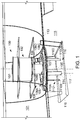
- FIG.1 is a perspective view of a cycloidal marine propulsion system 100, positioned in a marine vessel 101, according to embodiments of the present technology.
- the system 100 includes a primary drive 102.
- the primary drive 102 is a fully electric drive.
- the drive 102 is in one embodiment linked directly (e.g., without complex intermediary components such as clutches, step down or up gears) to a main vertical system shaft 104 of the system 100.
- the drive 102 is in this case referred to as a direct drive - e.g., a direct electric drive.
- the main shaft 104 is connected rigidly to a blade-mounting disc 106, and the two rotate about a main system axis 107 in operation.
- the system 100 also includes at least one angle sensor (not shown in detail) positioned on or adjacent the main shaft 104.
- a direct-drive arrangement promotes efficiency and fine control of the system 100, as losses from intermediate structure (e.g., couplings, such as a displaceable coupling, intermediate drive shafts such as a Cardan shaft, and step-down gears, with or without one or more clutches) that would otherwise be present are avoided or greatly limited.
- intermediate structure e.g., couplings, such as a displaceable coupling, intermediate drive shafts such as a Cardan shaft, and step-down gears, with or without one or more clutches
- a direct drive arrangement e.g., a direct electric drive
- a direct electric drive also allows very fast system response.
- a system controller is described further below.
- An electric motor 102 is in one embodiment a synchronous motor.
- the motor 102 may be a wound-field or permanent-magnet type of motor.
- the motor 102 is an induction-type motor.
- the motor 102 is a reluctance-type motor.
- the main drive 102 is not electric, or not entirely electric, being, e.g., a type of diesel engine or other internal combustion engine (e.g., Otto, petrol, gas turbine, etc.)
- the drive 102 can include hydraulic or pneumatic features, and connect directly or indirectly to the main shaft 104.
- the drive 102 is described further below, including in connection with FIG. 2 .
- the main assembly drive 102 includes or is connected to a geared system (not shown) for turning the main shaft 104.
- the geared system can include a gear ring, located on a periphery of the main shaft 104, connected to one or more pinion gears driven by one or more high speed motors.
- the blade-mounting disc 106 can be referred to by other names, such as main rotating assembly, or lower, inner, structure.
- the disc 106 rotates with respect to a lower, outer, structure or frame described further below in connection with FIG. 2 , and reference numeral 210.
- the drive 102 - e.g., direct drive - is in some embodiments controlled by a controller using a control map.
- the map comprises at least one algorithm according to which the main shaft can be controlled.
- the map can use as inputs, to determine main shaft operation, any of a wide variety of input data, such as any of output from the on-blade or adjacent-blade angle sensors, output from main assembly angle sensor(s), system power being used, system power available, present vessel speed, vessel attitude (e.g., roll or pitch), vessel speed desired or requested (by command of a vessel operator or the controller 300 ( FIG.
- the type of vessel will influence the method and type of control, since it is important for certain vessels to have accurate station-keeping characteristics, for example, platform supply vessels, or to have fast transit times, but still require improved maneuverability, such as in the case of ferry boats.
- the propulsion layout relative to the vessel center of gravity, or other vessel handling parameter, will require the control map to take into account those characteristics and parameters. For example, a tug customarily has two propulsion units at the furthest aft section of the hull, whereas a ferry could have the propulsion unit at the forward and after parts of the ship.
- the shaft 104 is controlled to accomplish desired vessel dynamics, such as vessel speed, vessel-speed vector, vessel thrust, and vessel attitude.
- the control map can also be configured to control the system 100 in a manner that lowers or minimizes drag created by one or more of the blades, thereby improving fuel efficiency.
- the control can also be performed to maintain or produce more thrust, and can effected in less time than conventional systems, as mentioned above.
- the control can include controlling movement of the main shaft 104. These control features are described further below in connection with FIGs. 3 and 4 .
- the system 100 further includes multiple actuators 108, such as electric motors, mounted locally to the propeller disc 106. Each actuator 108 is connected to respective system propeller blades 110.
- Each blade 110 includes a distal end 112 that is positioned below a bottom 113 of the vessel 101 and, during operation of the system 100, positioned in the water 115 in which the vessel 101 is positioned.
- Each actuator 108 is controlled by control signals received from a system controller, for instance, as described further below. While actuators 108 can be controlled to move their respective blades 110 according to some relationships (e.g., each blade is controlled to be positioned 20 degrees further in its rotation, about its blade axis, than a preceding adjacent blade on the disc 106), each actuator 108 is controlled to drive its respective blade 110 to move, or not move, independent of any motion of any of the other blades. That is, each actuator/blade pair can be controlled to move while each other actuator/blade is moved in any way, or kept from moving.
- one of the blades 110 can be rotated by a first angle in a first direction (e.g., clockwise) about its longitudinal (e.g., usually vertical) axis, for instance, another of the blades 110 can be controlled to move in any way, according to the control map, which can contain one or more algorithms for these purposes, such as by rotating in the same or an opposite direction by the same or another angle, or controlled to not move.
- a first direction e.g., clockwise
- the longitudinal (e.g., usually vertical) axis e.g., usually vertical) axis
- another of the blades 110 can be controlled to move in any way, according to the control map, which can contain one or more algorithms for these purposes, such as by rotating in the same or an opposite direction by the same or another angle, or controlled to not move.
- the system 100 also includes angle sensors on or adjacent each blade 110. These sensors are in one embodiment a part of the actuators 108. For simplicity, the sensors considered illustrated by the components 108 in the figures, though the sensors may be physically distinct from and/or connected to the actuators 108.
- the system 100 includes five actuators 108 (labeled respectively in the figures as 108A -E) connected to five respective propeller blades 110 - 110A-E. While five blades linked to five actuators are shown by way of example, it should be appreciated that the system 100 can include any number of actuators and respective blades.
- the actuators 108 in some embodiments are controlled by, or include, or are, one or more electric motors. These electric motors are considered shown by the same structure 108 in the figures.
- the actuators 108 in some embodiments include or are controlled by one or more other types of drives, such as pneumatic or hydraulic drives, considered shown by the same structure 108 in the figures.
- the actuators 108 in some embodiments include electric stepper motors. In one embodiment, the actuators are reluctance-type motors. Considerations in selecting or designing a motor of the actuators 108 include any or all of responsiveness (e.g., response time), strength, robustness, durability, and noise reduction.
- the actuators 108 can be operated to control velocity - speed and direction of movement, angular and/or linear - of the respective blades 110.
- each blade 110 changes in a rotation phase of the system 100 in which the rotating disc 106 is being rotated.
- the blades 110 being rotated by the disc 106 can create vectored thrust.
- Disc rotation and/or individual blade rotations can be, as mentioned above, controlled separately by a controller implementing a control map, or algorithm therein.
- the control map can use as inputs, to determine main shaft operation, any of various inputs, such as any of output from the on-blade or adjacent-blade angle sensors, output from main assembly angle sensor(s), system power being used, system power available, present vessel speed, vessel speed desired or requested (by, e.g., command of a vessel operator or the controller 300 ( FIG.
- Angular speed of any of the blades 110, about a respective blade axis 117 can be increased during the rotation phase to increase thrust.
- Angular speed of any blade, about its axis 117, can also be changed to decrease drag of the blade 110 in the water 115 when the vessel 101 is moving.
- the blades 110 are controlled individually to accomplish desired vessel dynamics - e.g., vessel speed vector, thrust, and attitude.
- the map, or algorithm can also be configured to control the vessel to lower or minimize drag created by one or more of the blades 110 against the water 115, to improve fuel efficiency, and the like.
- thrust created by each blade 110, and/or an amount of drag caused by each blade 110 moving through the water 115 can also be affected by posture or position of the blade 110 with respect to the disc 106 - e.g., tilt angle of the blade axis 117. Any one or more of the blades 110 can be moved selectively so that a lower, distal, tip 114 of the blade 110 moved radially outward, farther from the main system axis of rotation 107.
- Each blade can be moved in more than one manner at a time, as mentioned.
- a blade can be tilted (i.e., changing an angle of the blade axis 117 with respect to the main system axis 107), e.g., while it is being rotated about its blade axis 117.
- the blade can be tilted while being rotated about its blade axis, and both at the same time that the blade is being moved with the other blades about the main system axis.
- the blade can also be translated, as a whole, toward or away from the main system axis 107 while the blade is being moved in another way, such as being rotated about its axis 117 and/or by tilting - changing an angle of the blade axis 107 with respect to the system main axis 117.
- the system 100 or at least the vessel 101 includes a thrust plate 116.
- the plate 116 is in the illustrated embodiment suspended below the vessel 1 01 and positioned just below the tips 114 of the blades 110.
- posture of each blade 110 can also be controlled by the controller, implementing the control map, or algorithm, based on any of the controller inputs described herein.
- the controller and control map or algorithm are described further below regarding FIGs. 3 and 4 .
- the individual cycloidal-system blade control of the present technology using an electric drive controlling each of multiple cycloidal propeller blades, e.g., allows complex and fine control of blade angles.
- the blades can be controlled to accomplish benefits including desired vessel dynamics, such as mooring, translating, or linear movement - e.g., straight forward, reverse, or sideways motion.
- the blade control can, as referenced above, be performed, according to the control map, in ways to reduce drag. Drag can be reduced, e.g., by controlling individual blades separately so that each blade 110 creates a limited amount of friction with the water 115 through which the blades 110 are moving.
- the map can be configured to cause each blade 100 to, at every instance, be positioned and/or moved to create a desired thrust while minimizing drag created by the blade.
- the map can be configured to cause each blade 100 to, at every instance, be positioned and/or moved to minimize drag while not performing a thrust-creating action at the moment.
- An individual-blade-control arrangement also improves system response by limiting intermediate structure between the drive 102 and the lower disc 106, such as the complex mechanical gearing and sliders of the conventional VSP arrangements. In this way, time is limited between an input signal, initiated by a system controller or vessel operator, and resulting blade positioning or motion.
- FIG. 2 is a cut-away of the system 100 of FIG. 1 .
- the embodiment shown includes upper bearings 202 and lower bearings 204.
- the upper bearings 202 facilitate turning of the main shaft 104, or structure connected rigidly to the axis 104, with respect to adjacent static structure.
- the upper bearings 202 are positioned between an upper inner edge 206 connected rigidly to the main shaft 104 and an upper outer edge 208 connected to framing of the vessel 101.
- the lower bearings 204 facilitate turning of the main axis 104, or moving structure connected rigidly to the main shaft 104, with respect to adjacent static structure.
- the lower bearings 204 are positioned between, for instance, a lower inner edge 210 connected rigidly to the main shaft 104 or disc 106, and a lower outer edge 212 connected to adjacent framing of the vessel 101.
- FIG. 3 is a schematic diagram of a computing device 300 for use in performing functions of the present technology.
- the device 300 is configured to control various functions of the system 100, and can also be referred to as a controller.
- the computer device 300 includes a memory, or computer-readable medium 302, such as volatile medium, non-volatile medium, removable medium, and non-removable medium.
- a memory such as volatile medium, non-volatile medium, removable medium, and non-removable medium.
- computer-readable media and variants thereof, as used in the specification and claims, refer to tangible or non-transitory, computer-readable storage devices.
- storage media includes volatile and/or non-volatile, removable, and/or non-removable media, such as, for example, random access memory (RAM), read-only memory (ROM), electrically erasable programmable read-only memory (EEPROM), solid state memory or other memory technology, CD ROM, DVD, BLU-RAY, or other optical disk storage, magnetic tape, magnetic disk storage or other magnetic storage devices.
- RAM random access memory
- ROM read-only memory
- EEPROM electrically erasable programmable read-only memory
- solid state memory or other memory technology
- CD ROM compact disc read-only memory
- DVD digital versatile discs
- BLU-RAY Blu-ray Disc
- the computer device 300 also includes a computer processor 304 connected or connectable to the computer-readable medium 302 by way of a communication link 306, such as a computer bus.
- a computer processor 304 connected or connectable to the computer-readable medium 302 by way of a communication link 306, such as a computer bus.
- the processor could be multiple processors, which could include distributed processors or parallel processors in a single machine or multiple machines.
- the processor can be used in supporting a virtual processing environment.
- the processor could include a state machine, application specific integrated circuit (ASIC), programmable gate array (PGA) including a Field PGA, or state machine.
- references herein to processor executing code or instructions to perform operations, acts, tasks, functions, steps, or the like, could include the processor performing the operations directly and/or facilitating, directing, or cooperating with another device or component to perform the operations.
- the computer-readable medium 302 includes computer-executable instructions, or code 308.
- the computer-executable instructions 308 are executable by the processor 304 to cause the processor, and thus the computer device 300, to perform any combination of the functions described in the present disclosure.
- the instructions 308 include instructions or code 309 for controlling operation of the system 100 ( FIGs. 1 and 2 ).
- the code 309 routes, or maps, various conditions, indicated by conditions of the vessel 101 to output commands for one or more controllable components of the system 100.
- the code 309 may be referred to as a control map, mapping code, routing code, decision, and includes various algorithms defining any desired relationships between conditions and respective commands.
- Example input to the control map 309 includes those referenced above, such as any one or combination of: output from the on-blade or adjacent-blade angle sensors; output from main assembly angle sensor(s); system power being used; system power available; present vessel speed; vessel speed desired or requested (by, e.g., command of a vessel operator or the controller 300); wind speed; ambient water temperature; water depth; heading or position desired or requested (by, e.g., command of a vessel operator or the controller 300); a type or characteristic of the vessel 101; a propulsion layout; vessel-captain command; controller auto-generated command, etc.
- the control map 309 in one embodiment includes mapping, to one or more appropriate outputs, any of various combinations of such inputs and indications communicated by the inputs.
- Example indications include whether a device or condition is present/not present, on/off, percentages (e.g., percentage of vessel power being used or available), levels (e.g., vessel speed, water temperature), amounts (e.g., remaining batter power), and/or other values (e.g., angular, linear, or other position relating to the main axis 104 or any propeller blade(s) 110).
- Outputs include commands or signals instructing operation of one or more components of the system 100.
- the controllable components can include the main system drive 102 controlling rotation of the main axis 104.
- the main drive 102 in one embodiment includes an electric drive linked directly to the main axis 104. Aspects of the main axis 104 controlled include primarily direction of rotation and speed of rotation.
- the main axis rotation affects directly rotation of the blade-mounting disc 106, and so rotation of all of the blades 110, about the main system axis 107.
- the controllable components can also include each of the propeller blades 110.
- the blades 110 are configured and connected to the mounting structure or disc 106 to be moved independently of any motion or non-movement of any of the other blades.
- the configuration and arrangement allows the controller 300 to affect counter-clockwise rotation, about its axis 117, of a first of the blades 110, at a first speed, while adjacent blades 110 are kept from rotating about their axes 117, rotated clockwise, or rotated counter-clockwise at a different speed, etc.
- the blades 110 are in some embodiments also configured and connected to the mounting structure or disc 106 to be moved independently of any motion, non-movement, or rotational position of the vertical main assembly
- the mapping code 309 can be arranged in any manner connecting various inputs (e.g., vessel-captain commands and water conditions) with pre-set corresponding outputs (operational signals to system components).
- the mapping code 309 is in one embodiment arranged in an array format, such as a matrix, connecting various conditions (e.g., inputs) to corresponding outputs (e.g., component-specific control commands).
- the input can include the controller 300 or the vessel operator issuing, while the vessel is not creating, or not to be creating, thrust (e.g., gliding to a dock), a command requesting or relating to a desire to limit drag.
- the command can include or be related to a request for power or energy savings.
- Output in this example could include a command to the main drive 102 to stop (if not already stopped) and a command to one or any combination including all blades 100 to align to a present or desired vessel direction (i.e., so that main lateral portions of the blade(s) are facing perpendicular to the present or desired direction) so that the blades create limited drag as they are moving through the water 115 with the vessel 101.
- This may be an appropriate request, and resulting command, for situations in which a vessel (e.g., ferry) is approaching a stop at a slow speed sufficient for the vessel to reach a destination (e.g., dock being approached) if drag is minimized.
- power and energy e.g., fuel
- a vessel operator or the controller 300, can issue a command for power or energy saving vessel movement.
- the movement can include starting vessel movement in any desired direction - linear and/or turning.
- the cycloid system 100 can be used to create linear vessel movement in any direction.
- vessel speed can be maintained or reached with less thrust if drag is lowered.
- the vessel speed can be increased simply by reducing drag, without increasing rotation speed of the main axis (and so discs 106 and blades 110 in their collective rotation about the axis 107).
- Reducing drag can be accomplished by controlling each blade 110, independently, to at all times have a position that limits drag under the circumstances, such as to limit drag while also being moved to create the existing thrust level.
- control variable can include a rotational position of the blade 110 about the main axis 107
- the system is in some embodiments, as mentioned also configured so that each blade can be moved independently of any motion, non-movement, or rotational position of the vertical main assembly.
- One or more of the blades may at times be moved in the same manner, but generally each blade would be controlled to move and be positioned differently in this scenario.
- Such independent control is impossible using conventional cycloidal systems in which operation of each cycloid blade is linked to movement of the other blades by complex mechanical gearing.
- Blade adjustment can include controlling direction and rate of blade rotation about its axis 117.
- Blade adjustment can instead or also include controlling a pitch or tilt of the blade 110 - e.g., tilting the blade and its axis 117, such as by moving a lower tip of the blade outward, away from the main system axis 107.
- Thrust created by a blade 110 can be increased by adjusting or controlling any one or more of blade movement or position about its axis 117, its movement or position about the main axis 107, and a tilt angle of the blade (e.g., tilting the blade so a lower tip is moved away from or toward the main system axis 107).
- drag created by a blade 110, moving through the water 115 can be reduced by adjusting or controlling any one or more of blade movement or position about its axis 117, its movement or position about the main axis 107, and a tilt angle of the blade (e.g., tilting the blade so a lower tip is moved away from or toward the main system axis 107).
- system 100 is configured so that the blade 110 may be moved in its entirety away from the main axis to accomplish desired results (e.g., increasing thrust and/or reducing drag).
- the disc 106 or structure connected thereto would in this case be arranged to that each blade, or every blade together, can be moved away from the main axis 107.
- the lower tip of the blade 110 can be moved away from or toward the main axis 107 by an equal amount that an upper tip of the blade 110 is moved away from or toward the axis 107, so that the blade axis 117 angle is kept constant in the motion.
- the blade axis 117 can angle can change in the motion, such as by the lower tip 114 being moved out more slowly than an upper tip of the blade 110.
- each blade 110 is reduced when, e.g., each blade 110 is controlled to an optimum rotational position (i.e., about its axis 107) vertical position according to an absolute rotational position of the main assembly relative to the intended thrust direction.
- the reduction of drag can be achieved by modifying the local blade rotational position as the main assembly absolute position alters.
- linear vessel speed can be maintained while less power/energy is used. Due to the drag characteristics mentioned above, linear speed of the vessel 100 can be maintained while one or more aspect of the system 100 can be slowed, e.g., rotation of the main axis 104, simply by adjusting the blades in real time to reduce drag.
- the control map is configured to optimize the drag reduction according to factors such as vessel direction, speed, and desired speed based on inputs such as those from ship sensors including those sensing parameters including attitude in roll, pitch, and yaw.
- a greatest drag reduction effect is generated as part of providing, by blade control, steering and speed required.
- the blades providing thrust are not limited to providing thrust and steering functions - e.g., the blades moving in a forward direction, meaning returning towards the thrust provision position, can be used to provide direction thrust. This division of duties means that the blades may be more or less active during main assembly vertical axis positional change. In some instances, such as when the vessel is in deep water, or at full-away, the position of the vessel will need correcting without reduction in thrust.
- full-away refers to conditions, when operating a ship, wherein the ship is clear of navigation obstacles, and the propulsion system of the ship can be operated to any desired power level desired - e.g., a level to match a mission profile.
- full-away can involve the conditions allowing the ferry to operate at full power.
- Full-away can also refer to such operation of the ship (e.g., without limits, at full power, etc.).
- full-away could include the liner operating according to a schedule at a power level of between about 30 and about 100% of full load depending on factors such as distance between ports, weather, and so on.
- Full-away can also refer to operation of the propulsion system under conditions will not change notably in substantive ways during the voyage (e.g., during a full-away portion of the voyage) until nearing shore or navigation obstacles.
- the computer system 300 further comprises an input/output (I/O) device 310, or communication interface, such as a wireless transceiver and/or a wired communication port.
- I/O input/output
- the processor 304 executing the instructions 308, receives input from any of a wide variety of input sources 312 and provides output to any of a wide variety of outputs 314.
- Example input devices 312 include a temperature sensor (air, water, engine, motor, etc.), main-axis-shaft rotation-speed sensor, blade-position sensor, blade-rotation-speed sensor, other blade-position or movement sensor, vessel-speed sensor, the controller itself (providing, e.g., a command or other input by the processor from one portion of instructions (e.g., map 309 or other code 308) to another (e.g., the map 309), system power sensor or indicator, (by, e.g., a command of a vessel operator or the controller 300 ( FIG.
- Communications to/from the device 310 can be in the form of signals, messages, or packetized data, for example.
- the device 310 can include one or more transceivers, transmitters, and/or receivers.
- the device 310 can include wired and/or wireless interfaces for communicating with the input and output components 312, 314.
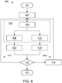
- FIG. 4 is a flow chart showing operations of a method 400 performed by the present technology, according to an embodiment of the present disclosure.
- the illustrated method 400 can be ended at any time. In certain embodiments, some or all steps of this process, and/or substantially equivalent steps are performed by execution of computer-readable instructions, such as the instructions 308 including the control map 309, stored or included on a computer readable medium, such as the memory 302 of the controller 300.
- the method 400 begins 401 and flow proceeds to block 402, whereat the controller obtains a vessel-kinematic, or motion or movement, command.
- the command is termed a kinematic, or movement or motion, command, and while the command can include initiating a vessel motion different than a current motion, the vessel-kinematic command can also be configured to (i) maintain an existing vessel motion, such as a current speed or direction, to (ii) stop the vehicle in any one or more directions (angular or linear), or to (iii) maintain a non-motion state.
- the obtaining operation can include receiving the command, being pushed to the processor 304.
- the obtaining includes the processor 304 retrieving the command - e.g., requesting and receiving the command.
- the command in some cases is generated by the controller 300 - i.e., by the processor 304 executing instructions 308.
- the command can be generated, e.g., in response to a determination by the controller 300 that a vessel speed and/or direction change is needed, such as to maintain a pre-set vessel course or to avoid an obstacle.
- the command can also be initiated by an order of a vessel operator, such as from a vessel captain selecting a hard or soft button indicating a power-saving or energy-saving mode, moving a soft or hard control for changing vessel direction, and/or moving a soft or hard vessel control for changing vessel speed.
- a vessel operator such as from a vessel captain selecting a hard or soft button indicating a power-saving or energy-saving mode, moving a soft or hard control for changing vessel direction, and/or moving a soft or hard vessel control for changing vessel speed.
- the controller accesses and processes the control map 309.
- the processor 304 executing the control map 309, obtains (e.g., receives or retrieves) input data to be used in processing the control map 309. Some or all of the inputs may already be present before or when the processor 304 accesses the control map 309, and some or all of the inputs may be retrieved by the processor 304 in response to determining the input(s) is/are needed in processing the control map.
- the inputs may be received from any of a wide variety of sources without departing from the scope of the present technology.
- the inputs can be received from the processor 304 executing certain aspects of the instructions, even of the control map 309.
- the inputs can be received from other electronic components of the vessel 100, such as any of the sensors described herein (vessel-speed, vessel-attitude, vessel-location, blade-rotation-speed, water-temperature, water-depth, etc.), or the like.
- the processor 304 determines (e.g., generates), based on the inputs received, one or more ways to adjust or maintain operation of at least one vessel component.
- Block 408 represents an example by which the processor 304, executing the map 309, determines a command for controlling (e.g., changing or maintaining) a rotational velocity of the main axis 104.
- Block 410 represents another example, by which the controller, executing the map 309, determines (e.g., generates) one or more commands for controlling (e.g., changing or maintaining) a position and/or rotational velocity (about blade axis 117) of a blade 110.
- the step 410 is in some implementations performed separately for each blade 110. The separate performance can be made substantially simultaneously.
- the controller determines the one or more commands for controlling position or rotational velocity of more than one blade at generally the same time.
- the main-axis command determined (indicating, e.g., an instruction to increase main-axis speed by 2 revs/min.) is provided to the main-axis driver 102 for maintaining or changing a rotational characteristic of the main shaft 104.
- the blade command determined (e.g., indicating an instruction to increase blade rotation about the blade axis 117) is provided to a blade actuator 108 (e.g., independent electric motor) for maintaining or changing a positional and/or movement characteristic (e.g., increasing blade rotation) for the blade 110.
- a blade actuator 108 e.g., independent electric motor
- the present operation 414 is in some implementations performed separately for each blade 110.
- the separate performance can be made substantially simultaneously.
- the processor 304 can generate commands for controlling position or rotational velocity of more than one blade at generally the same time, and commands for various blades can be related.
- actuators 108 can be controlled to move their respective blades 110 according to some relationships - e.g., each blade is controlled to be positioned 20 degrees further in its rotation, about its blade axis 117, than a preceding adjacent blade 110 of the blades 110 on the disc 106.
- the controller determines whether a new vessel-kinematic command (VKC) is present.
- the operation 416 includes a passive function of receiving, or not receiving, a new VKC.
- the command is termed a kinematic, or movement or motion, command, and while the command can include initiating a vessel motion different than a current motion
- the vessel-kinematic command can also be configured to (i) maintain an existing vessel motion, such as a current speed or direction, to (ii) stop the vehicle in any one or more directions (angular or linear), or to (iii) maintain a non-motion state.
- steps 404 et seq. such as for any further processing and any new output determinations that need to be made or provided in order to maintain, reach, or get closer to reaching a desired vessel state.
- Such subsequent iterations of the method 400 can include obtaining new (e.g., different) and/or updated sensor data at block 406.
- the new VKC is accepted, stored in cache or other memory as a current VKC, or otherwise processed by the processor 304 to give effect to the new VKC.
- steps 404 et seq. such as for any further processing and any new output determinations that need to be made or provided in order to maintain, reach, or get closer to reaching a desired vessel state.
- steps 404 et seq. such as for any further processing and any new output determinations that need to be made or provided in order to maintain, reach, or get closer to reaching a desired vessel state.
- such subsequent iterations of the method 400 can include obtaining new (e.g., different) and/or updated sensor data at block 406.
- the process 400 can be repeated, such as to effect one or more VKCs over time.
- the process 400 can be ended 421, such as by turning the controller 300 or the system 100 off, or a vessel operator selecting an off or sleep-mode.
- control features include controlling any or all of individual-blade position, individual-blade motion, main-axis-shaft position, and main-axis-shaft motion.
- These controls can be achieved using, e.g., individually-controllable blades, electric-motor blade actuators, and a direct-drive (e.g., electric motor) for main-shaft control.
- individually-controllable blades e.g., individually-controllable blades, electric-motor blade actuators, and a direct-drive (e.g., electric motor) for main-shaft control.
- direct-drive e.g., electric motor
- One of the primary advantages of the present technology is an ability to lower power and energy used by a marine cycloidal-propulsion system.
- noise e.g., underwater noise and/or noise passed to the air
- the savings result in more-efficient fuel consumption, lowered fuel cost (capital cost of operation), lower emissions, and extended ship range on the same amount of fuel.
- Technical advantages of the present technology include an ability to achieve greater speeds, including greater speeds at an equivalent power expenditure, by reducing drag.
- Another technical advantage includes improved vessel maneuverability. Improved vessel maneuverability is achievable by the ability to control each blade 110 individually in real time.
- Another benefit of the technology is a greater flexibility in designing vessels.
- the flexibility results from the greater maneuverability and speeds achievable by vessels incorporating the present technology.
- the vessel can be designed in previously unachievable ways without sacrificing maneuverability or speed.
- the flexibility can also result from an ability to use any of a variety of drives, such one or more diesel and/or electric motors to control the main drive shaft, and a distinct controllable electric motor for each of the plurality of cycloidal propeller blades.
Claims (15)
- Système de propulsion marine cycloïdal (100), comprenant :une pluralité de pales d'hélice (110A-F) présentant chacune un axe de pale primaire (117) respectif et étant reliées au disque (106) d'une manière permettant à une pale (110) de ladite pluralité de pales d'hélice (110A-E) d'être mise en rotation autour de son axe de pale primaire (117), indépendamment de toute rotation autour de l'axe de chacune des autres pales d'hélice (110) de ladite pluralité de pales d'hélice (110A-E) ;une pluralité d'actionneurs électriques (108A-E), chaque actionneur (108) étant relié à une pale respective des pales d'hélice (110) ; etun dispositif de commande (300) en communication, de façon sélective, avec chacun des actionneurs électriques (108) pour commander chacun des actionneurs (108) ;caractérisé en ce que chaque pale de la pluralité de pales d'hélice (110A-E) est reliée au disque (106) d'une manière permettant à la pale d'hélice (110) de s'incliner indépendamment de toute inclinaison de n'importe quelle autre des pales d'hélice (110) et/ou permettant à l'axe de pale primaire (117) de la pale d'hélice (110) de se déplacer en direction d'un axe de système principal (107) ou dans la direction opposée, indépendamment de tout mouvement de l'axe de pale primaire de n'importe quelle autre pale des pales d'hélice (110) en direction de l'axe de système principal (107) ou dans la direction opposée.
- Système de propulsion marine cycloïdal (100) selon la revendication 1, dans lequel le dispositif de commande (300) comporte des instructions exécutables par un ordinateur, comprenant un plan de commande, qui, lorsqu'elles sont exécutées par un processeur du dispositif de commande, font en sorte que le processeur commande séparément chacun des actionneurs électriques (108), conformément au plan de commande, le plan de commande comprenant de manière facultative un code qui, lorsqu'il est exécuté par le processeur, produit des données de sortie utilisées pour commander séparément chacun des actionneurs électriques (108), sur la base d'au moins une entrée de données sélectionnée dans un groupe comprenant :des données de capteur sur pale ;des données de capteur d'angle proche de pale ;des données de capteur d'angle d'assemblage principal ;des données de puissance de système actuelle ;des données de puissance de système disponible ;des données de vitesse de navire actuelle ;des données de vitesse de navire requise ;des données de vitesse du vent ;des données de température ambiante de l'eau ;des données de cap de navire actuel ;des données de cap de navire requis ;des données de position de navire actuelle ;des données de position de navire requise ;des données de profondeur d'eau ;des données de courants d'eau ;des données de type de navire ;des données de schéma de propulsion ;des ordres du capitaine du navire ; etdes ordres générés automatiquement par le dispositif de commande.
- Système de propulsion marine cycloïdal (100) selon la revendication 2, comprenant en outre :un arbre d'entraînement d'axe vertical primaire (104) relié au disque inférieur (106) ; etun entraînement d'axe primaire (102) relié à l'arbre d'entraînement (104) pour faire tourner l'arbre et, de ce fait, faire tourner le disque inférieur (106) ;dans lequel les instructions exécutables par un ordinateur, comprenant le plan de commande, lorsqu'elles sont exécutées par le processeur, font en sorte que le processeur commande le fonctionnement de l'entraînement d'axe primaire (102) conformément au plan de commande ; oudans lequel le dispositif de commande (300) est en communication avec l'entraînement d'axe primaire (102) pour commander l'entraînement en fonction du plan de commande.
- Système de propulsion marine cycloïdal (100) selon la revendication 2, comprenant en outre :un arbre d'entraînement d'axe vertical primaire (104) relié au disque inférieur (106) ; etun entraînement d'axe primaire (102) relié à l'arbre d'entraînement (104) pour faire tourner l'arbre et, de ce fait, faire tourner le disque inférieur (106) ;dans lequel l'entraînement d'axe primaire (102) comporte un moteur électrique relié directement à l'arbre d'entraînement d'axe vertical primaire (104).
- Système de propulsion marine cycloïdal (100) selon l'une quelconque des revendications précédentes, dans lequel le dispositif de commande (300) comprend des instructions exécutables par un ordinateur, englobant un plan de commande, qui, lorsqu'elles sont exécutées par un processeur du dispositif de commande, font en sorte que le processeur commande séparément chacun des actionneurs électriques (108) pour commander de façon indépendante l'inclinaison des pales, conformément au plan de commande.
- Système de propulsion marine cycloïdal (100) selon la revendication 1 ou 2, comprenant en outre :un arbre d'entraînement d'axe vertical primaire (104) relié au disque inférieur (106) ;dans lequel chacune des pales d'hélice (110A-E) est reliée au disque (106) d'une manière permettant à la pale (110) d'être mise en rotation autour de son axe de pale primaire (117), indépendamment de toute rotation autour de l'axe, de non rotation et de position de l'arbre d'entraînement d'axe vertical primaire (104).
- Procédé de commande d'un système de propulsion à machine cycloïdale (100) qui est utilisé dans un navire de transport maritime, le procédé comprenant les étapes suivantes :obtention, par un processeur d'un dispositif de commande (300), d'un ordre de cinématique de navire ;accès, par le processeur, à un plan de commande ;obtention, par le processeur, de données d'entrée indiquant au moins un état actuel associé au navire ;détermination, en utilisant l'ordre de cinématique de navire, le plan de commande et les données d'entrée, d'ordres de commande de pale distincts pour commander de façon indépendante chacune des pales d'hélice (110A-E) cycloïdales multiples, sachant que les ordres de commande de pale demandent un changement de position d'une pale d'hélice cycloïdale, en direction d'un axe de système principal (107) ou dans la direction opposée, et/ou l'inclinaison de la pale d'hélice (110) cycloïdale ; ettransmission des ordres de commande de pale à des actionneurs (108A-E) multiples, reliés à des pales respectives des pales d'hélice (110A-E) cycloïdales.
- Procédé selon la revendication 7, selon lequel l'ordre de cinématique de navire indique une demande pour arrêter le navire, maintenir une caractéristique actuelle de mouvement du navire ou maintenir une caractéristique actuelle de non mouvement du navire.
- Procédé selon la revendication 7, selon lequel
l'ordre de cinématique de navire est un ordre précédent de cinématique de navire ; et
le procédé comprend en outre la détermination pour savoir si un nouvel ordre de cinématique de navire est présent, et le fait d'agir suite au nouvel ordre de cinématique de navire, s'il est présent. - Procédé selon l'une quelconque des revendications 7 à 9, comprenant en outre les étapes suivantes :détermination, en utilisant l'ordre de cinématique de navire, le plan de commande et les données d'entrée, d'un ordre de commande d'entraînement d'axe principal pour commander un entraînement d'axe principal (102) du système (100) ; ettransmission des ordres de commande d'entraînement d'axe principal à l'entraînement d'axe principal (102).
- Procédé selon l'une quelconque des revendications 7 à 10, selon lequel les ordres de commande de pale demandent en outre un changement d'une rotation de pale autour d'un axe de pale (117).
- Procédé selon l'une quelconque des revendications 7 à 11, selon lequel :le navire comprend un arbre d'entraînement d'axe vertical primaire (104) ;chaque pale de la pluralité de pales d'hélice (110A-E) est reliée au disque (106) d'une manière permettant à la pale (110) d'être mise en rotation autour de son axe de pale primaire (117), indépendamment de toute rotation autour de l'axe, de non rotation et de position de l'arbre d'entraînement d'axe vertical primaire (104) ; et selon lequel l'étape de :
détermination, utilisant l'ordre de cinématique de navire, le plan de commande et les données d'entrée, d'ordres de commande de pale distincts pour commander de façon indépendante chacune des pales d'hélice (110A-E) cycloïdales multiples, comprend la détermination d'ordres de commande de pale pour commander les pales (110A-E), sachant que chaque pale (110) n'est pas limitée mécaniquement à une seule position de pale basée sur un mouvement de rotation autour d'un axe, un non mouvement et la position de l'arbre d'entraînement primaire (104). - Procédé de commande d'un système de propulsion à machine cycloïdale (100) qui est utilisé dans un navire de transport maritime, le procédé comprenant les étapes suivantes :accès, par un processeur, à un plan de commande ;obtention, par le processeur, de données d'entrée indiquant au moins un état actuel associé au navire ;détermination, en utilisant le plan de commande et les données d'entrée, d'ordres de commande de pale distincts pour commander de façon indépendante chacune des pales d'hélice (110A-E) cycloïdales multiples, sachant que les ordres de commande de pale demandent un changement de position d'une pale d'hélice cycloïdale, en direction d'un axe de système principal (107) ou dans la direction opposée, et/ou une inclinaison de la pale d'hélice (110) cycloïdale ; ettransmission des ordres de commande de pale à des actionneurs (108A-108E) multiples, reliés à des pales respectives des pales d'hélice (110A-E) cycloïdales.
- Procédé selon la revendication 13, comprenant en outre les étapes suivantes :détermination, en utilisant le plan de commande et les données d'entrée, d'un ordre de commande d'entraînement d'axe principal pour commander un entraînement d'axe principal (102) du système (100) ; ettransmission des ordres de commande d'entraînement d'axe principal à l'entraînement d'axe principal (102).
- Procédé selon la revendication 13 ou la revendication 14, selon lequel :le navire comprend un arbre d'entraînement d'axe vertical primaire (104) ;chaque pale de la pluralité de pales d'hélice (110A-E) est reliée au disque (106) d'une manière permettant à la pale d'hélice (110) d'être mise en rotation autour de son axe de pale primaire (117), indépendamment de toute rotation autour de l'axe, de non rotation et de position de l'arbre d'entraînement d'axe vertical primaire (104) ; et selon l'étape de :
détermination, utilisant l'ordre de cinématique de navire, le plan de commande et les données d'entrée, d'ordres de commande de pale distincts pour commander de façon indépendante chacune des pales d'hélice cycloïdales multiples, comprend la détermination d'ordres de commande de pale pour commander les pales (110A-E), sachant que chaque pale (110) n'est pas limitée mécaniquement à une seule position de pale basée sur un mouvement de rotation autour d'un axe, un non mouvement et la position de l'arbre d'entraînement primaire (104).
Priority Applications (5)
| Application Number | Priority Date | Filing Date | Title |
|---|---|---|---|
| EP14167934.0A EP2944556B1 (fr) | 2014-05-12 | 2014-05-12 | Système à propulsion marine cycloïdale |
| CA2891034A CA2891034A1 (fr) | 2014-05-12 | 2015-05-07 | Dispositif de propulsion marine cycloidal |
| BR102015010709-9A BR102015010709A2 (pt) | 2014-05-12 | 2015-05-11 | Sistema de propulsão marinha cicloide e método para controlar um sistema de propulsão de máquina cicloide |
| US14/709,551 US20150321740A1 (en) | 2014-05-12 | 2015-05-12 | Cycloidal marine-propulsion system |
| CN201510238577.0A CN105083515B (zh) | 2014-05-12 | 2015-05-12 | 摆线型舰船推进系统 |
Applications Claiming Priority (1)
| Application Number | Priority Date | Filing Date | Title |
|---|---|---|---|
| EP14167934.0A EP2944556B1 (fr) | 2014-05-12 | 2014-05-12 | Système à propulsion marine cycloïdale |
Publications (2)
| Publication Number | Publication Date |
|---|---|
| EP2944556A1 EP2944556A1 (fr) | 2015-11-18 |
| EP2944556B1 true EP2944556B1 (fr) | 2018-07-11 |
Family
ID=50687337
Family Applications (1)
| Application Number | Title | Priority Date | Filing Date |
|---|---|---|---|
| EP14167934.0A Active EP2944556B1 (fr) | 2014-05-12 | 2014-05-12 | Système à propulsion marine cycloïdale |
Country Status (5)
| Country | Link |
|---|---|
| US (1) | US20150321740A1 (fr) |
| EP (1) | EP2944556B1 (fr) |
| CN (1) | CN105083515B (fr) |
| BR (1) | BR102015010709A2 (fr) |
| CA (1) | CA2891034A1 (fr) |
Cited By (1)
| Publication number | Priority date | Publication date | Assignee | Title |
|---|---|---|---|---|
| WO2021249645A1 (fr) | 2020-06-11 | 2021-12-16 | Abb Oy | Appareil, procédé et programme d'ordinateur permettant de commander la propulsion d'un navire |
Families Citing this family (18)
| Publication number | Priority date | Publication date | Assignee | Title |
|---|---|---|---|---|
| CN105346694B (zh) * | 2015-11-30 | 2018-03-16 | 武汉理工大学 | 基于步进电机控制的船舶鲸尾轮推进器的结构装置 |
| US10640190B1 (en) | 2016-03-01 | 2020-05-05 | Brunswick Corporation | System and method for controlling course of a marine vessel |
| US10322787B2 (en) | 2016-03-01 | 2019-06-18 | Brunswick Corporation | Marine vessel station keeping systems and methods |
| CN105799894B (zh) * | 2016-03-22 | 2017-10-27 | 浙江机电职业技术学院 | 带放大机构的摆动导杆式摆线推进器 |
| FI128463B (en) * | 2016-10-17 | 2020-05-29 | Teknologian Tutkimuskeskus Vtt Oy | Meripropulsiojärjestelmä |
| US10671073B2 (en) * | 2017-02-15 | 2020-06-02 | Brunswick Corporation | Station keeping system and method |
| CN107187570B (zh) * | 2017-05-03 | 2019-04-30 | 武汉理工大学 | 一种具有高推进效率的船舶鲸尾轮推进器 |
| US10633072B1 (en) | 2018-07-05 | 2020-04-28 | Brunswick Corporation | Methods for positioning marine vessels |
| US10642273B2 (en) * | 2018-07-27 | 2020-05-05 | Caterpillar Inc. | Marine drive control of a marine vessel in a configured operation mode |
| US11820476B2 (en) | 2018-12-14 | 2023-11-21 | Abb Oy | Drive arrangement for a cycloidal marine propulsion unit, a cycloidal marine propulsion unit and a method of operating such a drive arrangement |
| WO2020120827A1 (fr) | 2018-12-14 | 2020-06-18 | Abb Oy | Unité de propulsion marine |
| EP3894313A1 (fr) * | 2018-12-14 | 2021-10-20 | ABB Oy | Unité de propulsion marine cycloïdale et navire marin équipé de celle-ci |
| FR3090571B1 (fr) * | 2018-12-19 | 2021-01-08 | Ecole Nat Superieure Darts Et Metiers Ensam | Systeme de propulsion ou de positionnement dynamique cycloidal pour un navire |
| CN110466725A (zh) * | 2019-08-21 | 2019-11-19 | 西北工业大学 | 一种最大迎角可调的滑杆式摆线桨推进器 |
| CN116096633A (zh) * | 2020-06-11 | 2023-05-09 | Abb公司 | 水上交通工具的推进系统的控制方法及推进系统 |
| CN111645815B (zh) * | 2020-06-15 | 2021-05-07 | 朱运兰 | 一种河道清理船 |
| WO2023061605A1 (fr) * | 2021-10-15 | 2023-04-20 | Ge Energy Power Conversion Technology Ltd | Propulseurs |
| SE2251001A1 (en) * | 2022-08-27 | 2024-02-28 | Humphree Ab | A system for controlling movements of a marine surface vessel |
Family Cites Families (15)
| Publication number | Priority date | Publication date | Assignee | Title |
|---|---|---|---|---|
| DE19637786C1 (de) * | 1996-09-17 | 1998-02-26 | Voith Hydro Gmbh Schiffstechni | Zykloidalpropeller |
| US2090052A (en) * | 1934-08-20 | 1937-08-17 | Kurt F J Kirsten | Aircraft |
| US3371635A (en) * | 1966-09-07 | 1968-03-05 | Nancy Lee Seeley | Submersible vessel |
| DE3041483C2 (de) * | 1980-11-04 | 1982-11-25 | J.M. Voith Gmbh, 7920 Heidenheim | Amphibienfahrzeug |
| US5462406A (en) * | 1993-08-19 | 1995-10-31 | Vitron Systems Inc. | Cyclodial propulsion system |
| DE4337761C2 (de) * | 1993-11-05 | 1995-09-21 | Voith Gmbh J M | Rotierendes Maschinenteil, insbesondere Rotor eines Zykloidal-Schiffspropellers |
| NO305981B1 (no) * | 1994-10-21 | 1999-08-30 | Blohm & Voss Int | Anordning for skip, til bruk som aktivt manoevreringsorgan uavhengig av hoveddrivverket |
| DE19637833C1 (de) * | 1996-09-17 | 1998-02-05 | Voith Hydro Gmbh Schiffstechni | Zykloidalpropeller |
| DE10060067A1 (de) * | 2000-12-01 | 2002-06-13 | Doczyck Wolfgang | Propulsionsantrieb und Verfahren zum Antreiben eines Schiffs |
| DE102005022168A1 (de) * | 2005-05-13 | 2006-11-16 | Christian Thieme | Zykloidalpropeller |
| DE102005056469B4 (de) * | 2005-11-26 | 2016-03-17 | Voith Turbo Marine Gmbh & Co. Kg | Verfahren zur Dämpfung der Rollbewegung eines Wasserfahrzeuges, insbesondere zur Rollstabilisierung von Schiffen |
| CN101327839A (zh) * | 2008-06-05 | 2008-12-24 | 浙江大学 | 以步进电机作为控制机构的直翼摆线推进器 |
| US20100172759A1 (en) * | 2009-01-08 | 2010-07-08 | Sullivan John T | Retractable wind turbines |
| CN101863306B (zh) * | 2010-03-18 | 2012-01-04 | 西北工业大学 | 一种全向矢量推力摆线螺旋桨 |
| CN103723259B (zh) * | 2013-12-31 | 2016-04-06 | 浙江大学 | 叶片摆动机构及包括该机构的用于船舶的摆线推进器 |
-
2014
- 2014-05-12 EP EP14167934.0A patent/EP2944556B1/fr active Active
-
2015
- 2015-05-07 CA CA2891034A patent/CA2891034A1/fr not_active Abandoned
- 2015-05-11 BR BR102015010709-9A patent/BR102015010709A2/pt not_active IP Right Cessation
- 2015-05-12 CN CN201510238577.0A patent/CN105083515B/zh active Active
- 2015-05-12 US US14/709,551 patent/US20150321740A1/en not_active Abandoned
Non-Patent Citations (1)
| Title |
|---|
| None * |
Cited By (1)
| Publication number | Priority date | Publication date | Assignee | Title |
|---|---|---|---|---|
| WO2021249645A1 (fr) | 2020-06-11 | 2021-12-16 | Abb Oy | Appareil, procédé et programme d'ordinateur permettant de commander la propulsion d'un navire |
Also Published As
| Publication number | Publication date |
|---|---|
| EP2944556A1 (fr) | 2015-11-18 |
| US20150321740A1 (en) | 2015-11-12 |
| CN105083515B (zh) | 2019-05-31 |
| CN105083515A (zh) | 2015-11-25 |
| CA2891034A1 (fr) | 2015-11-12 |
| BR102015010709A2 (pt) | 2018-03-20 |
Similar Documents
| Publication | Publication Date | Title |
|---|---|---|
| EP2944556B1 (fr) | Système à propulsion marine cycloïdale | |
| JP5138419B2 (ja) | 舶用推進システム | |
| US7429202B2 (en) | Outboard motor control system | |
| JP5138412B2 (ja) | 舶用推進システム | |
| JP4980948B2 (ja) | 舶用推進システム | |
| EP2338785A2 (fr) | Systèmes et procédés d'orientation d'un navire pour améliorer la poussée disponible | |
| US20110153125A1 (en) | Systems and Methods for Orienting a Marine Vessel to Minimize Pitch or Roll | |
| JP2007532408A5 (fr) | ||
| US7527009B2 (en) | Method for damping of the rolling motion of a water vehicle, in particular for roll stabilization of ships | |
| CN104149961B (zh) | 一种恒速变距直翼全向推进器 | |
| CN107741744B (zh) | 一种海洋观测平台的最优艏向控制方法 | |
| CN111712431A (zh) | 一种船舶操纵控制装置 | |
| US9296453B2 (en) | Control apparatus for boat | |
| CN108528737B (zh) | 一种直升机电驱动尾桨控制系统及方法 | |
| US20220177102A1 (en) | Method for controlling marine hybrid systems | |
| EP3353049B1 (fr) | Procédé et agencement permettant de man uvrer un navire | |
| CN114030579B (zh) | 一种无人船稳定控制方法及推进装置 | |
| JP2016216018A (ja) | 操船システム | |
| CN109334940A (zh) | 一种直翼舵转向控制方法及系统 | |
| EP2990327B1 (fr) | Système électrique de navire et procédé | |
| CN110831851B (zh) | 水上船舶推进单元校准方法 | |
| JP6000923B2 (ja) | 船舶の制御装置 | |
| CN113759924B (zh) | 一种用于无人控制系统的非线性控制方法及装置 | |
| CN116520834A (zh) | 一种低能耗的无人船巡航方法 | |
| JP6084912B2 (ja) | 船舶の制御装置 |
Legal Events
| Date | Code | Title | Description |
|---|---|---|---|
| PUAI | Public reference made under article 153(3) epc to a published international application that has entered the european phase |
Free format text: ORIGINAL CODE: 0009012 |
|
| AK | Designated contracting states |
Kind code of ref document: A1 Designated state(s): AL AT BE BG CH CY CZ DE DK EE ES FI FR GB GR HR HU IE IS IT LI LT LU LV MC MK MT NL NO PL PT RO RS SE SI SK SM TR |
|
| AX | Request for extension of the european patent |
Extension state: BA ME |
|
| 17P | Request for examination filed |
Effective date: 20160510 |
|
| RBV | Designated contracting states (corrected) |
Designated state(s): AL AT BE BG CH CY CZ DE DK EE ES FI FR GB GR HR HU IE IS IT LI LT LU LV MC MK MT NL NO PL PT RO RS SE SI SK SM TR |
|
| RIC1 | Information provided on ipc code assigned before grant |
Ipc: B63H 1/10 20060101AFI20171220BHEP |
|
| GRAP | Despatch of communication of intention to grant a patent |
Free format text: ORIGINAL CODE: EPIDOSNIGR1 |
|
| STAA | Information on the status of an ep patent application or granted ep patent |
Free format text: STATUS: GRANT OF PATENT IS INTENDED |
|
| INTG | Intention to grant announced |
Effective date: 20180207 |
|
| GRAS | Grant fee paid |
Free format text: ORIGINAL CODE: EPIDOSNIGR3 |
|
| GRAA | (expected) grant |
Free format text: ORIGINAL CODE: 0009210 |
|
| STAA | Information on the status of an ep patent application or granted ep patent |
Free format text: STATUS: THE PATENT HAS BEEN GRANTED |
|
| AK | Designated contracting states |
Kind code of ref document: B1 Designated state(s): AL AT BE BG CH CY CZ DE DK EE ES FI FR GB GR HR HU IE IS IT LI LT LU LV MC MK MT NL NO PL PT RO RS SE SI SK SM TR |
|
| REG | Reference to a national code |
Ref country code: GB Ref legal event code: FG4D |
|
| REG | Reference to a national code |
Ref country code: CH Ref legal event code: EP |
|
| REG | Reference to a national code |
Ref country code: AT Ref legal event code: REF Ref document number: 1016600 Country of ref document: AT Kind code of ref document: T Effective date: 20180715 |
|
| REG | Reference to a national code |
Ref country code: IE Ref legal event code: FG4D |
|
| REG | Reference to a national code |
Ref country code: DE Ref legal event code: R096 Ref document number: 602014028168 Country of ref document: DE |
|
| REG | Reference to a national code |
Ref country code: NL Ref legal event code: MP Effective date: 20180711 |
|
| REG | Reference to a national code |
Ref country code: LT Ref legal event code: MG4D |
|
| REG | Reference to a national code |
Ref country code: AT Ref legal event code: MK05 Ref document number: 1016600 Country of ref document: AT Kind code of ref document: T Effective date: 20180711 |
|
| PG25 | Lapsed in a contracting state [announced via postgrant information from national office to epo] |
Ref country code: NL Free format text: LAPSE BECAUSE OF FAILURE TO SUBMIT A TRANSLATION OF THE DESCRIPTION OR TO PAY THE FEE WITHIN THE PRESCRIBED TIME-LIMIT Effective date: 20180711 |
|
| PG25 | Lapsed in a contracting state [announced via postgrant information from national office to epo] |
Ref country code: SE Free format text: LAPSE BECAUSE OF FAILURE TO SUBMIT A TRANSLATION OF THE DESCRIPTION OR TO PAY THE FEE WITHIN THE PRESCRIBED TIME-LIMIT Effective date: 20180711 Ref country code: BG Free format text: LAPSE BECAUSE OF FAILURE TO SUBMIT A TRANSLATION OF THE DESCRIPTION OR TO PAY THE FEE WITHIN THE PRESCRIBED TIME-LIMIT Effective date: 20181011 Ref country code: NO Free format text: LAPSE BECAUSE OF FAILURE TO SUBMIT A TRANSLATION OF THE DESCRIPTION OR TO PAY THE FEE WITHIN THE PRESCRIBED TIME-LIMIT Effective date: 20181011 Ref country code: AT Free format text: LAPSE BECAUSE OF FAILURE TO SUBMIT A TRANSLATION OF THE DESCRIPTION OR TO PAY THE FEE WITHIN THE PRESCRIBED TIME-LIMIT Effective date: 20180711 Ref country code: RS Free format text: LAPSE BECAUSE OF FAILURE TO SUBMIT A TRANSLATION OF THE DESCRIPTION OR TO PAY THE FEE WITHIN THE PRESCRIBED TIME-LIMIT Effective date: 20180711 Ref country code: IS Free format text: LAPSE BECAUSE OF FAILURE TO SUBMIT A TRANSLATION OF THE DESCRIPTION OR TO PAY THE FEE WITHIN THE PRESCRIBED TIME-LIMIT Effective date: 20181111 Ref country code: GR Free format text: LAPSE BECAUSE OF FAILURE TO SUBMIT A TRANSLATION OF THE DESCRIPTION OR TO PAY THE FEE WITHIN THE PRESCRIBED TIME-LIMIT Effective date: 20181012 Ref country code: PL Free format text: LAPSE BECAUSE OF FAILURE TO SUBMIT A TRANSLATION OF THE DESCRIPTION OR TO PAY THE FEE WITHIN THE PRESCRIBED TIME-LIMIT Effective date: 20180711 Ref country code: FI Free format text: LAPSE BECAUSE OF FAILURE TO SUBMIT A TRANSLATION OF THE DESCRIPTION OR TO PAY THE FEE WITHIN THE PRESCRIBED TIME-LIMIT Effective date: 20180711 Ref country code: LT Free format text: LAPSE BECAUSE OF FAILURE TO SUBMIT A TRANSLATION OF THE DESCRIPTION OR TO PAY THE FEE WITHIN THE PRESCRIBED TIME-LIMIT Effective date: 20180711 |
|
| PG25 | Lapsed in a contracting state [announced via postgrant information from national office to epo] |
Ref country code: LV Free format text: LAPSE BECAUSE OF FAILURE TO SUBMIT A TRANSLATION OF THE DESCRIPTION OR TO PAY THE FEE WITHIN THE PRESCRIBED TIME-LIMIT Effective date: 20180711 Ref country code: ES Free format text: LAPSE BECAUSE OF FAILURE TO SUBMIT A TRANSLATION OF THE DESCRIPTION OR TO PAY THE FEE WITHIN THE PRESCRIBED TIME-LIMIT Effective date: 20180711 Ref country code: AL Free format text: LAPSE BECAUSE OF FAILURE TO SUBMIT A TRANSLATION OF THE DESCRIPTION OR TO PAY THE FEE WITHIN THE PRESCRIBED TIME-LIMIT Effective date: 20180711 Ref country code: HR Free format text: LAPSE BECAUSE OF FAILURE TO SUBMIT A TRANSLATION OF THE DESCRIPTION OR TO PAY THE FEE WITHIN THE PRESCRIBED TIME-LIMIT Effective date: 20180711 |
|
| REG | Reference to a national code |
Ref country code: DE Ref legal event code: R097 Ref document number: 602014028168 Country of ref document: DE |
|
| PG25 | Lapsed in a contracting state [announced via postgrant information from national office to epo] |
Ref country code: EE Free format text: LAPSE BECAUSE OF FAILURE TO SUBMIT A TRANSLATION OF THE DESCRIPTION OR TO PAY THE FEE WITHIN THE PRESCRIBED TIME-LIMIT Effective date: 20180711 Ref country code: IT Free format text: LAPSE BECAUSE OF FAILURE TO SUBMIT A TRANSLATION OF THE DESCRIPTION OR TO PAY THE FEE WITHIN THE PRESCRIBED TIME-LIMIT Effective date: 20180711 Ref country code: CZ Free format text: LAPSE BECAUSE OF FAILURE TO SUBMIT A TRANSLATION OF THE DESCRIPTION OR TO PAY THE FEE WITHIN THE PRESCRIBED TIME-LIMIT Effective date: 20180711 Ref country code: RO Free format text: LAPSE BECAUSE OF FAILURE TO SUBMIT A TRANSLATION OF THE DESCRIPTION OR TO PAY THE FEE WITHIN THE PRESCRIBED TIME-LIMIT Effective date: 20180711 |
|
| PLBE | No opposition filed within time limit |
Free format text: ORIGINAL CODE: 0009261 |
|
| STAA | Information on the status of an ep patent application or granted ep patent |
Free format text: STATUS: NO OPPOSITION FILED WITHIN TIME LIMIT |
|
| PG25 | Lapsed in a contracting state [announced via postgrant information from national office to epo] |
Ref country code: SK Free format text: LAPSE BECAUSE OF FAILURE TO SUBMIT A TRANSLATION OF THE DESCRIPTION OR TO PAY THE FEE WITHIN THE PRESCRIBED TIME-LIMIT Effective date: 20180711 Ref country code: DK Free format text: LAPSE BECAUSE OF FAILURE TO SUBMIT A TRANSLATION OF THE DESCRIPTION OR TO PAY THE FEE WITHIN THE PRESCRIBED TIME-LIMIT Effective date: 20180711 Ref country code: SM Free format text: LAPSE BECAUSE OF FAILURE TO SUBMIT A TRANSLATION OF THE DESCRIPTION OR TO PAY THE FEE WITHIN THE PRESCRIBED TIME-LIMIT Effective date: 20180711 |
|
| 26N | No opposition filed |
Effective date: 20190412 |
|
| PG25 | Lapsed in a contracting state [announced via postgrant information from national office to epo] |
Ref country code: SI Free format text: LAPSE BECAUSE OF FAILURE TO SUBMIT A TRANSLATION OF THE DESCRIPTION OR TO PAY THE FEE WITHIN THE PRESCRIBED TIME-LIMIT Effective date: 20180711 |
|
| REG | Reference to a national code |
Ref country code: DE Ref legal event code: R119 Ref document number: 602014028168 Country of ref document: DE |
|
| REG | Reference to a national code |
Ref country code: CH Ref legal event code: PL |
|
| PG25 | Lapsed in a contracting state [announced via postgrant information from national office to epo] |
Ref country code: CH Free format text: LAPSE BECAUSE OF NON-PAYMENT OF DUE FEES Effective date: 20190531 Ref country code: LI Free format text: LAPSE BECAUSE OF NON-PAYMENT OF DUE FEES Effective date: 20190531 Ref country code: MC Free format text: LAPSE BECAUSE OF FAILURE TO SUBMIT A TRANSLATION OF THE DESCRIPTION OR TO PAY THE FEE WITHIN THE PRESCRIBED TIME-LIMIT Effective date: 20180711 |
|
| REG | Reference to a national code |
Ref country code: BE Ref legal event code: MM Effective date: 20190531 |
|
| PG25 | Lapsed in a contracting state [announced via postgrant information from national office to epo] |
Ref country code: LU Free format text: LAPSE BECAUSE OF NON-PAYMENT OF DUE FEES Effective date: 20190512 |
|
| PG25 | Lapsed in a contracting state [announced via postgrant information from national office to epo] |
Ref country code: TR Free format text: LAPSE BECAUSE OF FAILURE TO SUBMIT A TRANSLATION OF THE DESCRIPTION OR TO PAY THE FEE WITHIN THE PRESCRIBED TIME-LIMIT Effective date: 20180711 |
|
| PG25 | Lapsed in a contracting state [announced via postgrant information from national office to epo] |
Ref country code: DE Free format text: LAPSE BECAUSE OF NON-PAYMENT OF DUE FEES Effective date: 20191203 Ref country code: IE Free format text: LAPSE BECAUSE OF NON-PAYMENT OF DUE FEES Effective date: 20190512 |
|
| PG25 | Lapsed in a contracting state [announced via postgrant information from national office to epo] |
Ref country code: BE Free format text: LAPSE BECAUSE OF NON-PAYMENT OF DUE FEES Effective date: 20190531 |
|
| PG25 | Lapsed in a contracting state [announced via postgrant information from national office to epo] |
Ref country code: PT Free format text: LAPSE BECAUSE OF FAILURE TO SUBMIT A TRANSLATION OF THE DESCRIPTION OR TO PAY THE FEE WITHIN THE PRESCRIBED TIME-LIMIT Effective date: 20181111 |
|
| PG25 | Lapsed in a contracting state [announced via postgrant information from national office to epo] |
Ref country code: CY Free format text: LAPSE BECAUSE OF FAILURE TO SUBMIT A TRANSLATION OF THE DESCRIPTION OR TO PAY THE FEE WITHIN THE PRESCRIBED TIME-LIMIT Effective date: 20180711 |
|
| PG25 | Lapsed in a contracting state [announced via postgrant information from national office to epo] |
Ref country code: MT Free format text: LAPSE BECAUSE OF FAILURE TO SUBMIT A TRANSLATION OF THE DESCRIPTION OR TO PAY THE FEE WITHIN THE PRESCRIBED TIME-LIMIT Effective date: 20180711 Ref country code: HU Free format text: LAPSE BECAUSE OF FAILURE TO SUBMIT A TRANSLATION OF THE DESCRIPTION OR TO PAY THE FEE WITHIN THE PRESCRIBED TIME-LIMIT; INVALID AB INITIO Effective date: 20140512 |
|
| PG25 | Lapsed in a contracting state [announced via postgrant information from national office to epo] |
Ref country code: MK Free format text: LAPSE BECAUSE OF FAILURE TO SUBMIT A TRANSLATION OF THE DESCRIPTION OR TO PAY THE FEE WITHIN THE PRESCRIBED TIME-LIMIT Effective date: 20180711 |
|
| PGFP | Annual fee paid to national office [announced via postgrant information from national office to epo] |
Ref country code: FR Payment date: 20230420 Year of fee payment: 10 |
|
| PGFP | Annual fee paid to national office [announced via postgrant information from national office to epo] |
Ref country code: GB Payment date: 20230420 Year of fee payment: 10 |