EP2943090B1 - Glueless composite panel and method for the glueless connection of two panel elements - Google Patents
Glueless composite panel and method for the glueless connection of two panel elements Download PDFInfo
- Publication number
- EP2943090B1 EP2943090B1 EP13834383.5A EP13834383A EP2943090B1 EP 2943090 B1 EP2943090 B1 EP 2943090B1 EP 13834383 A EP13834383 A EP 13834383A EP 2943090 B1 EP2943090 B1 EP 2943090B1
- Authority
- EP
- European Patent Office
- Prior art keywords
- panel
- strip
- groove
- elements
- face
- Prior art date
- Legal status (The legal status is an assumption and is not a legal conclusion. Google has not performed a legal analysis and makes no representation as to the accuracy of the status listed.)
- Active
Links
- 239000002131 composite material Substances 0.000 title claims description 33
- 238000000034 method Methods 0.000 title claims description 10
- 238000010168 coupling process Methods 0.000 claims description 92
- 230000008878 coupling Effects 0.000 claims description 91
- 238000005859 coupling reaction Methods 0.000 claims description 91
- 230000036961 partial effect Effects 0.000 claims description 25
- 238000013461 design Methods 0.000 description 13
- 239000000463 material Substances 0.000 description 11
- 230000002829 reductive effect Effects 0.000 description 10
- 239000004033 plastic Substances 0.000 description 8
- 230000008901 benefit Effects 0.000 description 7
- 238000004519 manufacturing process Methods 0.000 description 6
- 230000003068 static effect Effects 0.000 description 6
- 239000000853 adhesive Substances 0.000 description 5
- 230000001070 adhesive effect Effects 0.000 description 5
- 238000000576 coating method Methods 0.000 description 5
- 230000006378 damage Effects 0.000 description 5
- 230000000694 effects Effects 0.000 description 5
- 239000000314 lubricant Substances 0.000 description 5
- 238000003860 storage Methods 0.000 description 5
- 239000011248 coating agent Substances 0.000 description 4
- 238000000926 separation method Methods 0.000 description 4
- 238000013459 approach Methods 0.000 description 3
- 238000011161 development Methods 0.000 description 3
- 230000018109 developmental process Effects 0.000 description 3
- 239000003292 glue Substances 0.000 description 3
- 230000000630 rising effect Effects 0.000 description 3
- 206010016256 fatigue Diseases 0.000 description 2
- 210000004013 groin Anatomy 0.000 description 2
- 238000005304 joining Methods 0.000 description 2
- 230000008569 process Effects 0.000 description 2
- 230000003313 weakening effect Effects 0.000 description 2
- 239000002023 wood Substances 0.000 description 2
- 206010047571 Visual impairment Diseases 0.000 description 1
- 230000006978 adaptation Effects 0.000 description 1
- 238000005452 bending Methods 0.000 description 1
- 239000003795 chemical substances by application Substances 0.000 description 1
- 238000010276 construction Methods 0.000 description 1
- 238000011109 contamination Methods 0.000 description 1
- 239000007822 coupling agent Substances 0.000 description 1
- 230000001808 coupling effect Effects 0.000 description 1
- 230000001419 dependent effect Effects 0.000 description 1
- 238000001035 drying Methods 0.000 description 1
- 239000011521 glass Substances 0.000 description 1
- 230000006872 improvement Effects 0.000 description 1
- 229910052500 inorganic mineral Inorganic materials 0.000 description 1
- 238000003780 insertion Methods 0.000 description 1
- 230000037431 insertion Effects 0.000 description 1
- 239000004922 lacquer Substances 0.000 description 1
- 239000011707 mineral Substances 0.000 description 1
- 230000003287 optical effect Effects 0.000 description 1
- 238000011084 recovery Methods 0.000 description 1
- 230000009467 reduction Effects 0.000 description 1
- 230000000284 resting effect Effects 0.000 description 1
- 210000002023 somite Anatomy 0.000 description 1
- 238000004381 surface treatment Methods 0.000 description 1
- 230000002522 swelling effect Effects 0.000 description 1
- 208000024891 symptom Diseases 0.000 description 1
- 238000012546 transfer Methods 0.000 description 1
- 208000029257 vision disease Diseases 0.000 description 1
- 230000000007 visual effect Effects 0.000 description 1
- 230000004393 visual impairment Effects 0.000 description 1
Images


Classifications
-
- E—FIXED CONSTRUCTIONS
- E04—BUILDING
- E04B—GENERAL BUILDING CONSTRUCTIONS; WALLS, e.g. PARTITIONS; ROOFS; FLOORS; CEILINGS; INSULATION OR OTHER PROTECTION OF BUILDINGS
- E04B1/00—Constructions in general; Structures which are not restricted either to walls, e.g. partitions, or floors or ceilings or roofs
- E04B1/38—Connections for building structures in general
- E04B1/541—Joints substantially without separate connecting elements, e.g. jointing by inter-engagement
-
- A—HUMAN NECESSITIES
- A47—FURNITURE; DOMESTIC ARTICLES OR APPLIANCES; COFFEE MILLS; SPICE MILLS; SUCTION CLEANERS IN GENERAL
- A47B—TABLES; DESKS; OFFICE FURNITURE; CABINETS; DRAWERS; GENERAL DETAILS OF FURNITURE
- A47B47/00—Cabinets, racks or shelf units, characterised by features related to dismountability or building-up from elements
- A47B47/04—Cabinets, racks or shelf units, characterised by features related to dismountability or building-up from elements made mainly of wood or plastics
- A47B47/042—Panels connected without frames
-
- E—FIXED CONSTRUCTIONS
- E04—BUILDING
- E04B—GENERAL BUILDING CONSTRUCTIONS; WALLS, e.g. PARTITIONS; ROOFS; FLOORS; CEILINGS; INSULATION OR OTHER PROTECTION OF BUILDINGS
- E04B1/00—Constructions in general; Structures which are not restricted either to walls, e.g. partitions, or floors or ceilings or roofs
- E04B1/38—Connections for building structures in general
- E04B1/61—Connections for building structures in general of slab-shaped building elements with each other
- E04B1/6108—Connections for building structures in general of slab-shaped building elements with each other the frontal surfaces of the slabs connected together
- E04B1/612—Connections for building structures in general of slab-shaped building elements with each other the frontal surfaces of the slabs connected together by means between frontal surfaces
- E04B1/6125—Connections for building structures in general of slab-shaped building elements with each other the frontal surfaces of the slabs connected together by means between frontal surfaces with protrusions on the one frontal surface co-operating with recesses in the other frontal surface
- E04B1/6137—Connections for building structures in general of slab-shaped building elements with each other the frontal surfaces of the slabs connected together by means between frontal surfaces with protrusions on the one frontal surface co-operating with recesses in the other frontal surface the connection made by formlocking
-
- F—MECHANICAL ENGINEERING; LIGHTING; HEATING; WEAPONS; BLASTING
- F16—ENGINEERING ELEMENTS AND UNITS; GENERAL MEASURES FOR PRODUCING AND MAINTAINING EFFECTIVE FUNCTIONING OF MACHINES OR INSTALLATIONS; THERMAL INSULATION IN GENERAL
- F16B—DEVICES FOR FASTENING OR SECURING CONSTRUCTIONAL ELEMENTS OR MACHINE PARTS TOGETHER, e.g. NAILS, BOLTS, CIRCLIPS, CLAMPS, CLIPS OR WEDGES; JOINTS OR JOINTING
- F16B12/00—Jointing of furniture or the like, e.g. hidden from exterior
- F16B12/10—Jointing of furniture or the like, e.g. hidden from exterior using pegs, bolts, tenons, clamps, clips, or the like
- F16B12/12—Jointing of furniture or the like, e.g. hidden from exterior using pegs, bolts, tenons, clamps, clips, or the like for non-metal furniture parts, e.g. made of wood, of plastics
- F16B12/125—Jointing of furniture or the like, e.g. hidden from exterior using pegs, bolts, tenons, clamps, clips, or the like for non-metal furniture parts, e.g. made of wood, of plastics using mortise and tenon joints
-
- F—MECHANICAL ENGINEERING; LIGHTING; HEATING; WEAPONS; BLASTING
- F16—ENGINEERING ELEMENTS AND UNITS; GENERAL MEASURES FOR PRODUCING AND MAINTAINING EFFECTIVE FUNCTIONING OF MACHINES OR INSTALLATIONS; THERMAL INSULATION IN GENERAL
- F16B—DEVICES FOR FASTENING OR SECURING CONSTRUCTIONAL ELEMENTS OR MACHINE PARTS TOGETHER, e.g. NAILS, BOLTS, CIRCLIPS, CLAMPS, CLIPS OR WEDGES; JOINTS OR JOINTING
- F16B5/00—Joining sheets or plates, e.g. panels, to one another or to strips or bars parallel to them
- F16B5/07—Joining sheets or plates, e.g. panels, to one another or to strips or bars parallel to them by means of multiple interengaging protrusions on the surfaces, e.g. hooks, coils
-
- F—MECHANICAL ENGINEERING; LIGHTING; HEATING; WEAPONS; BLASTING
- F16—ENGINEERING ELEMENTS AND UNITS; GENERAL MEASURES FOR PRODUCING AND MAINTAINING EFFECTIVE FUNCTIONING OF MACHINES OR INSTALLATIONS; THERMAL INSULATION IN GENERAL
- F16B—DEVICES FOR FASTENING OR SECURING CONSTRUCTIONAL ELEMENTS OR MACHINE PARTS TOGETHER, e.g. NAILS, BOLTS, CIRCLIPS, CLAMPS, CLIPS OR WEDGES; JOINTS OR JOINTING
- F16B12/00—Jointing of furniture or the like, e.g. hidden from exterior
- F16B12/44—Leg joints; Corner joints
- F16B12/46—Non-metal corner connections
- F16B2012/463—Non-metal corner connections for wooden members without additional elements
-
- F—MECHANICAL ENGINEERING; LIGHTING; HEATING; WEAPONS; BLASTING
- F16—ENGINEERING ELEMENTS AND UNITS; GENERAL MEASURES FOR PRODUCING AND MAINTAINING EFFECTIVE FUNCTIONING OF MACHINES OR INSTALLATIONS; THERMAL INSULATION IN GENERAL
- F16B—DEVICES FOR FASTENING OR SECURING CONSTRUCTIONAL ELEMENTS OR MACHINE PARTS TOGETHER, e.g. NAILS, BOLTS, CIRCLIPS, CLAMPS, CLIPS OR WEDGES; JOINTS OR JOINTING
- F16B5/00—Joining sheets or plates, e.g. panels, to one another or to strips or bars parallel to them
- F16B5/06—Joining sheets or plates, e.g. panels, to one another or to strips or bars parallel to them by means of clamps or clips
- F16B5/0607—Joining sheets or plates, e.g. panels, to one another or to strips or bars parallel to them by means of clamps or clips joining sheets or plates to each other
- F16B5/0621—Joining sheets or plates, e.g. panels, to one another or to strips or bars parallel to them by means of clamps or clips joining sheets or plates to each other in parallel relationship
- F16B5/0635—Joining sheets or plates, e.g. panels, to one another or to strips or bars parallel to them by means of clamps or clips joining sheets or plates to each other in parallel relationship fastened over the edges of the sheets or plates
-
- Y—GENERAL TAGGING OF NEW TECHNOLOGICAL DEVELOPMENTS; GENERAL TAGGING OF CROSS-SECTIONAL TECHNOLOGIES SPANNING OVER SEVERAL SECTIONS OF THE IPC; TECHNICAL SUBJECTS COVERED BY FORMER USPC CROSS-REFERENCE ART COLLECTIONS [XRACs] AND DIGESTS
- Y10—TECHNICAL SUBJECTS COVERED BY FORMER USPC
- Y10T—TECHNICAL SUBJECTS COVERED BY FORMER US CLASSIFICATION
- Y10T29/00—Metal working
- Y10T29/49—Method of mechanical manufacture
- Y10T29/49826—Assembling or joining
- Y10T29/49828—Progressively advancing of work assembly station or assembled portion of work
-
- Y—GENERAL TAGGING OF NEW TECHNOLOGICAL DEVELOPMENTS; GENERAL TAGGING OF CROSS-SECTIONAL TECHNOLOGIES SPANNING OVER SEVERAL SECTIONS OF THE IPC; TECHNICAL SUBJECTS COVERED BY FORMER USPC CROSS-REFERENCE ART COLLECTIONS [XRACs] AND DIGESTS
- Y10—TECHNICAL SUBJECTS COVERED BY FORMER USPC
- Y10T—TECHNICAL SUBJECTS COVERED BY FORMER US CLASSIFICATION
- Y10T403/00—Joints and connections
- Y10T403/70—Interfitted members
- Y10T403/7045—Interdigitated ends
Definitions
- the invention relates to a glueless panel assembly according to the features in the preamble of claim 1 and a method for glueless connection of at least two panel elements of a panel assembly according to the features of claim 14.
- a variety of furnishings include or are formed by panel members. In addition to purely decorative arrangements, they form the predominant part of the design of mostly closed rooms, especially in the form of furniture. Depending on their functionality as seating furniture, tables or storage furniture, these can also be used outdoors.
- a seating, storage or storage area In order to create a seating, storage or storage area, these have a mostly horizontally aligned plate element, which is either mounted or set up directly on a wall area or via an additional arrangement on a wall or on a floor area. Their design usually provides at least two plate elements which are connected to one another in an angled orientation.
- Storage or container furniture in particular, has an open body made of three or more panel elements, which can be closed, for example, via a door, if necessary.
- the mostly self-supporting base element of such a piece of furniture has a basic construction which in most cases is composed of at least two plate elements.
- the individual plate elements can, for example, take on the function of a side part, a base or a cover.
- their plate elements which are assembled to form a frame, are connected to one another via a rear wall which, in the form of a disk, stabilizes and fixes the position of the individual plate elements relative to one another.
- Glued connections offer an extremely durable way of connecting individual panel elements to one another.
- the adhesive connection required in each case depends on the expected load and, in particular, on the materials used for the plate elements. In the usual way, such plate elements are provided, for example, made of wood or wooden materials.
- these can also be formed from plastic or glass and mineral components, for example.
- the DE 20 2009 008 825 U1 discloses a further possibility for assembling two plate elements, which can be connected to one another without glue by means of coupling means arranged on them.
- this has at least a first panel element and a second panel element which, when connected to one another, enclose an angle not equal to 180 degrees between them.
- the coupling means each extend parallel to a longitudinal direction of the end faces of the plate elements.
- the coupling means are formed in that the first plate element has a first groove which is arranged on its end face.
- the second plate element has a groove which is arranged on an inner edge region laterally adjoining its end face and is delimited laterally by an edge strip merging into the end face.
- the groove arranged in the end face of the first plate element is delimited by a tongue and a first edge strip that is set back with respect to the tongue.
- the first edge strip is designed to be elastic in that it is exposed via a slot arranged in the side surface of the first plate element and can be resiliently displaced into it during the coupling process.
- a glueless corpus and a method for glueless connection of wall elements of a corpus are known.
- Each end face of a wall element has a groove and a tongue, so that when the wall elements are connected, the respective tongue and groove of one of the wall elements are in engagement with the other tongue and groove of the adjacent wall element.
- Another glueless panel composite is, for example, from the WO 2011/160173 A1 known.
- the present invention is based on the object of providing a glueless panel assembly and a method for glueless connection of at least two panel elements to form a panel assembly, the panel elements enabling their robustly designed coupling means to be easily manufactured should, via which the plate elements can be put together within a very short time to form a durable plate assembly that can be dismantled without any problems if necessary without fatigue or even destruction of the coupling elements.
- the objective part of the object is achieved in a glueless panel assembly with the features of claim 1.
- the procedural part of this object is achieved by a method for glueless connection of at least two panel elements to form a panel assembly with the features of claim 14.
- the glueless panel assembly comprises at least a first panel element and a second panel element, the two panel elements being connectable to one another via coupling means arranged thereon and each extending parallel to a longitudinal direction of their respective end faces.
- the individual coupling means are formed in that the first plate element has a first groove on its first face, while the second plate element comprises a second groove, which, however, is not arranged on its second face, but on an inner edge region laterally adjoining its second face is.
- the groove arranged in the inner edge region of the second plate element is laterally delimited by a second edge strip merging into the second end face of the second plate element.
- the first groove introduced at the end of the first plate element is delimited by a tongue and a first edge strip that is set back with respect to the tongue.
- both the first edge strip and the second edge strip of the respective plate elements are interrupted several times in their extension parallel to the longitudinal direction of the respective end faces.
- both the first edge strip are divided into individual first strip sections and the second edge strip is divided into individual second strip sections.
- the respective strip sections are arranged on the panel elements to be connected in such a way that, in their coupled state, the first strip sections and the second strip sections undercut at least regionally. In this situation, the first strip sections and the second strip sections mutually.
- the first strip sections of the first plate element are arranged in the second groove of the second plate element, while the second strip sections of the second plate element are arranged in the first groove of the first plate element.
- the particular advantage here is that there is no need for any deliberately resilient parts of the coupling means. As a result, no resistance whatsoever has to be overcome when coupling the individual plate elements, which otherwise can only be overcome by laterally displacing part of the coupling means. By dispensing with resilient parts of the coupling means, a possible weakening of the material is already effectively prevented during the joining of the plate elements.
- the coupling means designed in this way allow their robust, unyielding design, which also produces a durable connection between the plate elements over a long period of time.
- At least one of the first strip sections or the second strip sections can be designed at least regionally in a wedge shape.
- Said wedge shape extends parallel to the longitudinal direction of the respective end face.
- the wedge shape has the effect that the strip section designed in this way requires an increasing expenditure of force in the event of a constant relative movement between the two plate elements which are in engagement with one another via the coupling means in order to be pushed further into the respective groove parallel to the longitudinal direction of one of the end faces. The reason for this is the increasing contact pressure between the at least regionally wedge-shaped strip section and the otherwise uniformly wide groove over its course.
- At least one of the grooves located in the area of the strip sections can have such a wedge-shaped course, while the strip section corresponding to the groove configured in this way has no or a different wedge shape of at least one of its areas.
- the wedge-shaped configuration must be designed so that when a Bar section in one of the grooves whose tension in the contact area with one another is increased in that the respective cross section of the bar section is either thickened or the corresponding cross section of the groove is tapered.
- edge strips subdivided into individual strip sections Another advantage of the edge strips subdivided into individual strip sections is that the plate elements to be connected do not have to be pushed into one another over the entire length of the edge strips, but are only moved closer to one another and locked to one another via an oppositely oriented relative movement.
- the individual strip sections of one of the plate elements are pushed through between the strip sections of the respective other plate element until their respective position runs in the plane of the corresponding groove.
- the individual strip sections are then shifted in the respective grooves in that the two plate elements are displaced opposite one another, parallel to the longitudinal direction of one of the end faces. In this position, the respective strip sections of the first plate element and of the second plate element undercut at least regionally.
- the plate elements to be connected to one another generally have the same width, measured parallel to the longitudinal direction of their end faces.
- the individual strip sections are preferably arranged on the respective plate elements in such a way that they are aligned with one another when the plate elements are connected to one another. This ensures that the edges running between the end faces of the respective plate element run in the same plane when the two plate elements are coupled.
- the respective strip sections are preferably arranged in such a way that they are aligned with one another when the edges pointing towards a narrow side of the panel assembly run in the same plane after the relative movement of the two panel elements to one another.
- the second end face of the second plate element has a head strip extending parallel to its longitudinal direction.
- the tongue of the first plate element has a coupling channel corresponding to the head strip.
- the head strip of one plate element is arranged in the latching channel of the other plate element in the coupled state of the two plate elements.
- the two interconnected plate elements have a guide through the head strip arranged in the coupling channel, within which the two plate elements are held during the relative movement to one another.
- the coupling channel and the head strip arranged therein create additional contact surfaces which, due to their distance from a possible pivot point between the coupled plate elements, increase the bending stiffness required in each case of the plate assembly created in this way.
- the head strip can be adapted in shape to the cross section of the coupling channel. In this way, the tightest possible fit is created between the head strip and the coupling channel, which enables a tight and thus low-movement connection between the two plate elements.
- both the first strip sections can be arranged at a distance and the second strip sections can be arranged at a distance from one another.
- the respective distance between the first strip sections or the second strip sections is particularly preferably constant.
- the respective distance between the first strip sections or the second strip sections can also be different. Different means that, for example, two directly adjacent strip sections of a plate element have a distance from one another which differs from the distance between these strip sections and a respectively adjacent strip section.
- the respective number of the strip sections on the respective plate element can be set.
- a large number of strip sections has the effect that the panel elements connected to one another have a large number of undercuts.
- strip sections arranged at a large distance from one another reduce their number, so that the amount of possible undercuts within the panel assembly is also reduced.
- areas which are subject to higher loads in relation to the coupling of the two plate elements can have a large number of strip sections.
- less stressed areas can be designed in such a way that the strip sections arranged there are reduced to a minimum due to their large distances from one another.
- the individual strip sections have a length which is determined in particular by the respective distance between the individual strip sections.
- an edge strip is first created on one of the plate elements, which is then interrupted into individual strip sections by appropriate material removal. If the individual interruptions turn out to be small in relation to the respective longitudinal direction of the edge strips, while the distances between the individual interruptions are large, a corresponding length of the individual strip sections is achieved. In contrast, the interruptions can also occupy larger areas, so that when the individual interruptions are arranged closely, the length of the respective strip sections is significantly reduced.
- the distance between the first strip sections preferably corresponds to at least one length of the second strip sections measured parallel to the longitudinal direction of the second end face.
- the distance between the second strip sections can correspond to at least one length of the first strip sections measured parallel to the longitudinal direction of the first end face.
- the respective lengths of the strip sections of a plate element are adapted to the distances between the individual strip sections of the other plate element. This ratio creates the largest possible area for the necessary undercuts.
- first strip sections are also adapted to the shape of the second groove and the second strip sections are correspondingly shaped to the first groove.
- second strip sections are correspondingly shaped to the first groove.
- respective shape-adapted cross-sectional shape of the strip sections and grooves can also relate to only a few sections or areas thereof.
- the tongue of the first plate element can merge into an outer side surface opposite the inner side surface of the first plate element.
- the tongue protrudes seamlessly from the outer side surface of the first plate element or merges into it, without impairing the overall visual impression of the outer side surface by any interruption or even a jump in cross-section.
- this creates a connection of the two plate elements that is as slim as possible, the respective coupling means of which are arranged in such a way that, when the two plate elements are connected, they cover one another and are therefore not visually perceptible.
- the individual coupling means can be fixed to the respective plate element, for example via an adhesive connection or other connection means.
- the respective coupling means are particularly preferably an integral part of the respective plate element of the same material.
- the coupling means are formed from the respective plate elements. If the plate elements consist, for example, of a wood material, the coupling means can already be molded onto the respective plate element during manufacture. In contrast, the coupling means can also be formed by a corresponding removal of material from the material of the respective plate element.
- the tongue of the first plate element can be designed in such a way that it completely covers the second end face of the second plate element when the plate elements are coupled.
- any possible visual impairment of the panel assembly in the area of the coupling means is largely reduced, since the optically perceptible separation of the panel assembly into the individual panel elements is reduced to just an interruption between the tongue of the first panel element and the second face of the second panel element. Said interruption can only be perceived in the connected state of the two plate elements on one side surface of the plate assembly in relation to the second plate element.
- the individual coupling means are advantageously designed to be rigid. As a result, an impact that cannot be ruled out in practice when coupling the individual plate elements does not lead to any damage to the coupling means which reduces the coupling.
- there are no deliberately elastic areas of the coupling means which can be damaged in particular in the event of continuous loading or even overstressing during use or even during the connection process.
- possible overstretching in certain areas cannot be ruled out, as a result of which plastic deformation or even damage to the elastic part of the coupling means occurs, which significantly reduces the actual coupling effect within the plate assembly.
- a first partial region of the tongue which lies opposite the outer side face of the first plate element and adjoins the first end face, can be designed in such a way that it extends parallel to the outer side face.
- the tongue has a constant thickness in relation to its extension perpendicular to the first edge strip.
- the tongue can also be designed in such a way that at least a first partial area of the tongue and an outer side surface of the first plate element enclose a first angle of less than 90 degrees between them. In this way, at least a first portion of the tongue is opposite the outer side surface of the first plate element inclined.
- the second plate element can be designed in such a way that at least a second partial area of its second end face and an outer edge area opposite the inner edge area enclose a second angle between them, which is also less than 90 degrees.
- a second partial area of the second end face is also inclined with respect to the outer edge area of the second plate element.
- either the first sub-area of the first plate element or the second sub-area of the second plate element can be designed to be inclined.
- both the first sub-area and the second sub-area of the two plate elements can also be designed to be inclined in this way.
- the particular advantage is that the individual partial areas of the respective end faces of the two plate elements are adapted to the respective coupling situation.
- the coupling situation means the respective position of the two plate elements with respect to one another in relation to their included angle between them.
- the inclination of at least one of the partial areas increases the respective contact surface between the plate elements, whereby any stresses between the plate elements are reduced with the same load.
- the optical properties of the panel assembly can be set such that the inclination of the first partial area of the tongue shifts the optically perceptible connection plane between the panel elements as close as possible to the outer side surface of the first panel element.
- the respective partial areas are coordinated with one another with regard to their inclination such that they lie flat on one another when the two interconnected plate elements are in the intended angular position.
- the entire area of the partial areas can be used to transfer the stresses that occur between them.
- the connecting plane run in such a way that it intersects an outer corner located at the intersection of the respective extensions of the outer edge region of the second plate element and the outer side surface of the first plate element. In this way, said connecting plane runs through the outer corner of the panel composite formed from the panel elements.
- the connecting plane which is otherwise optically perceptible on one of the outer side surfaces of the interconnected panel elements, can be shifted in the outer corner area of the panel assembly. This results in the typical look of two mitered and interconnected panel elements.
- the panel assembly according to the invention can comprise at least three such panel elements, the respective panel elements in the coupled state forming a glueless body, for example for a piece of furniture in the form of a self-contained frame. In this way, four or more such plate elements can also be put together to form an open or self-contained frame.
- the plate elements can preferably each have a groove running within the assembled frame.
- a rear wall can be arranged within this circumferential groove.
- the width of the groove is advantageously based on the respective thickness of the rear wall in order to accommodate it with as little play as possible.
- the groove can extend into the corner areas of the self-contained frame, so that a circumferential groove is formed within the frame.
- the respective grooves on the inner side surfaces of the frame can be at least partially spaced from the respective inner corner areas of the self-contained frame.
- the rear wall to be used has at least one recessed and thus not fully formed corner area, the size of which is based on the part of the plate elements remaining between the grooves and the corner area. This configuration makes it possible to leave a corresponding opening in an inner corner area within the rear wall, in the area of which there is no optically disruptive groove within the plate elements.
- the rear wall can be designed in such a way that its dimensions are based on the inner dimensions of the closed frame plus at least part of the respective depth of the groove made in at least one of the plate elements.
- the rear wall in the installed state can be spaced apart from at least one plate element, more precisely its inner side surface.
- at least one wedge element is provided, which can then be arranged between this inner side surface of the plate element and the rear wall.
- the wedge element bridges the gap created between the rear wall and the inner side surface of a plate element, wherein it positions the rear wall, which is otherwise movable within the remaining grooves, in its position.
- the rear wall, which is otherwise movable within the groove is fixed in its position by the wedge element and is spaced apart from the one inner side surface of the plate element.
- a corresponding tension can be built up between the rear wall and at least two opposing plate elements, which is transferred to the individual inner corner areas and thus to the coupling means of the plate elements connected to one another.
- At least one of the plate elements can be designed to be shorter in the region of the groove provided for the rear wall.
- an end face of this plate element jumps back behind the plane of the groove of adjacent plate elements.
- this can then be fixed in its intended position within the frame.
- the locking lug is intended to secure the wedge element in its intended position from accidentally falling out or being pulled out.
- the locking lug engages behind the rear wall, while it is arranged between an inner side surface of one of the plate elements and the rear wall.
- the locking lug can also reach behind a region of a plate element, for example into a recess, in order to be fixed in its position. Depending on the configuration, this recess can also be the groove within the plate elements which is used anyway to accommodate the rear wall.
- the first edge strip of the first plate element can merge into the inner side surface of the first plate element.
- the inner side surface of the first plate element merges directly into the second groove of the second plate element in the assembled state of the plate elements. This achieves the greatest possible spacing between the individual parts of the coupling means, the inner lever arms thus enlarged leading to a reduction in the stresses occurring in the connection area between the plate elements.
- the first edge strip can also be spaced apart from the inner side surface of the first plate element.
- the part rising from the first edge strip to the inner side surface of the first plate element can here provide an additional partial area against which the second plate element can be supported within the plate assembly. In this way, the forces occurring in the connection area between the plate elements can be transferred to other partial areas, whereby the respective loads can also be reduced by reducing the stresses.
- the present invention showed an extremely simple possibility for the production of a glueless panel composite and its necessary panel elements, which can be produced within a very short time and can be both plugged together and dismantled without any problems.
- the overall robust design of the individual coupling means enables an extremely durable connection between the plate elements, which enables a durable coupling even after several joining and loosening processes of the connection.
- Dispensing with any elastically designed parts of the coupling means enables practical handling without excessive caution when assembling the panel assembly. In this way, possible overstressing of the otherwise elastic and thus mostly filigree parts of the coupling means during assembly or dismantling and storage is also excluded. The associated symptoms of fatigue are not to be expected thanks to the robust design of the coupling means.
- the glueless panel composite creates a visually appealing and practical option for quickly completing individual panel elements to form a panel composite.
- the dismantling of the panel assembly which takes place if necessary, is also accompanied by no need to displace or bend any parts of the coupling means, since this only requires a relative movement of the panel elements connected to one another in opposite directions.
- the solution consists in a method for glueless connection of at least two panel elements to form a panel assembly, which include an angle not equal to 180 degrees between them.
- said plate elements have coupling means which can be brought into engagement with one another and which comprise individual edge strips which are divided into individual strip sections.
- the plate elements are first brought closer together until at least one of the first strip sections of the first plate element has slid between two of the second strip sections of the second plate element and in the plane of a second groove arranged on an inner edge area of the second plate element and at least one of the second Bar sections is located in the plane of a first groove arranged on a first end face of the first plate element.
- the plate elements to be connected to one another are then displaced in opposite directions to one another via a limited relative movement.
- Said relative movement takes place in a locking direction running parallel to a longitudinal direction of the first or the second end face.
- the relative movement is carried out until the first strip section is arranged at least in sections in the second groove and the second strip section is arranged at least in sections in the first groove. In this position, the strip sections pushed one behind the other undercut one another, at least in sections, so that separation of the interconnected plate elements is no longer possible due to the undercuts formed.
- the particular advantage is that this enables a durable connection between the plate elements while dispensing with elastic, in particular resilient parts of the connecting means.
- the measures known in the prior art for forming such a panel composite require mostly the bridging of a possible holding force, which subsequently secures the connected plate elements against undesired loosening of the connection.
- a resistance must first be overcome in which, for example, a region of the coupling means is elastically displaced in order to correspond, for example, with an undercut after its recovery in the connected state of the plate elements.
- correspondingly high forces are usually necessary, which not infrequently lead to the destruction or at least to the weakening of the further connection possibilities of the plate elements separated from one another.
- the second plate element has a head strip arranged on its second end face.
- the head strip extends in the longitudinal direction of the second end face.
- the first plate element can have a coupling channel formed on its tongue, which corresponds to the head strip of the second plate element.
- the coupling means can also have an additional projection and a recess corresponding to it.
- the projection arranged on the coupling means engages in the recess also arranged on the coupling means.
- the particular advantage here is an approach of the wall elements which initially takes place without significant resistance, whereupon the actual, in particular durable connection between the plate elements takes place via the locking movement in the locking direction.
- the coupling means of at least one plate element can be designed to reduce friction, at least in some areas. This against the background of the simplest possible connection of the plate elements, which occurs as a result of the relative movement and the associated interlocking of the strip sections.
- the coupling means can either be designed to be as slippery as possible or else have a corresponding coating.
- the desired sliding ability of the plate elements to be connected to one another can also only be brought about shortly before they are coupled to one another, for example by using a suitable lubricant.
- the aim is to reduce the sometimes high static friction in the contacting areas of the plate elements, in particular the coupling means, in order to facilitate the actual locking movement.
- these can also have friction-reducing coatings made of a different material.
- a coating can be, for example, a lacquer or a plastic. These form a self-adhesive coating, which is preferably not subject to any significant wear even after several locking and unlocking movements of the plate elements.
- the coating can also be designed as a lubricant, which in turn is not firmly connected to the areas in question, but adheres to them in the form of a lubricant.
- the areas in contact with one another can have increased static friction, at least in some areas, so that the connection between the plate elements created by the locking movement cannot be easily broken.
- the static friction set specifically in the connection area must be overcome in order to move the individual strip sections out of their positions forming the undercuts.
- both the locking and the unlocking movement would accordingly be inhibited.
- the lubricants created in this way can also be set in such a way that the respective friction is different depending on the direction. In this case, the sliding friction would preferably be reduced during the locking movement, whereas it is increased in the opposite unlocking direction.
- the static friction in the interconnected state of the plate elements can also be increased in this way.
- connection areas in question are at least partially provided with a means which changes its properties over an adjustable period of time.
- this means can initially function as a lubricant during the locking movement, while it in the coupled state of the plate elements with one another reduces or even loses its sliding ability or changes to an adhesive effect.
- the agent in question can, for example, resinify over time, as a result of which the connection created between the plate elements is adhesively reinforced.
- connection area can also be set by additional components which are arranged at least in areas or sections.
- additional components which are arranged at least in areas or sections.
- Conceivable for this are, for example, sliding strips in the form of plastic strips, which are arranged, for example, in the groove and / or the coupling channel, so that the corresponding edge strip or the corresponding strip sections and the head strip slide on one of the plastic strips.
- Said plastic strips can either be loosely inserted or else connected to the relevant areas of the plate elements. In the latter case, these can also be arranged on the parts of the coupling means that engage in the groove and / or the coupling channel. In addition to a planar cross-sectional configuration or a cross-sectional configuration adapted to the course of the coupling channel, said plastic strips can also have a U-shape, so that they also cover the respective flanks of the coupling means at least in some areas. In this context, it is also conceivable that such a plastic band in the form of an insert is adapted to the entire cross-sectional configuration of the coupling means of a plate element.
- an extremely slidable connection could be created, which over a certain period of time brings about an extremely firm connection of the plate elements to one another through an increase in cross-section.
- the increase in cross section could be set in such a way that any unlocking movement for separating the plate elements is either made more difficult or even prevented.
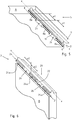
- the interconnected plate elements A, B are aligned with one another in such a way that they enclose an angle c between them that is not equal to 180 degrees.
- An angle c of 90 degrees is shown here.
- Figure 2 shows the connection area of the composite panel 1 Figure 1 in a detailed view.
- a connecting plane d runs between the first plate element A and the second plate element B, which can be optically perceived as a separating joint 4 from an outside 3 of the plate assembly 1.
- Figure 3 shows the first plate element A of Figure 2 in a representation separated from the second plate element B.
- the first plate element A comprises a first end face 5, in which a first groove 6 directed into the first plate element A is arranged.
- the first groove 6 is laterally bounded by a tongue 7 and a first edge strip 8 that is set back with respect to the tongue 7.
- the tongue 7 also has a coupling channel 9 directed into it, which is offset in relation to its orientation by 90 degrees to the first groove 6 and adjoins it.
- the coupling channel 9 is designed in such a way that it has a rounded base 10.
- the first groove 6 is designed in such a way that its base 11 is oriented at right angles to flanks 12a, 12b of the first groove 6 that are oriented parallel to one another.
- the lower flank 12b of the first groove 6 at the same time forms a side of the first edge strip 8 which lies opposite an inner side surface 13 of the first plate element A.
- said flank 12b has a parallel course to the inner side surface 13 of the first plate element A.
- the coupling channel 9 arranged in the tongue 7 is spaced apart from a head region 14 located at the end of the tongue 7, so that a first partial region 15 directed towards the inner side surface 13 of the first plate element A results.
- the first sub-area 15 is parallel to an outer side surface opposite the inner side surface 13 of the first plate element A 16 aligned.
- the first partial area 15 and the head area 14 of the tongue 7 merge into one another at right angles.
- the tongue 7 is configured in its area opposite the first sub-area 15 that it merges seamlessly into the outer side surface 16 and without any jump.
- the side of the first edge strip 8 opposite the flank 12b of the first groove 6 is also designed in such a way that it merges seamlessly into the inner side surface 13 of the first plate element A without any offset.
- Both the first edge strip 8 and the first groove 6 have chamfers 17 arranged thereon, the first edge strip 8 merging via the chamfers 17 into both the lower flank 12b of the first groove 6 and into the inner side surface 13 of the first plate element A. , while the base 11 of the first groove 6 merges into the flanks 12a, 12b of the first groove 6 via the chamfers 17.
- Figure 4 shows the corresponding counterpart to the first plate element A.
- Figure 3 in the form of the second plate element B. Opposite Figure 2 this is also removed from the panel assembly 1 in the present case, whereby the design of its coupling means 2 becomes clear.
- the second plate element B has an inner edge area 18 and an outer edge area 19 opposite the inner edge area 18, between which a second end face 20 of the second plate element B extends at the end.
- the inner edge area 18 and the outer edge area 19 of the second plate element B directly adjoin the second end face 20.
- the inner edge region 18 has a second groove 21 which has a base 22 running parallel to the inner edge region 18 and flanks 23a, 23b rising from this to the inner edge region 18.
- the flanks 23a, 23b of the second groove 21 are aligned parallel to one another and are each arranged at right angles to the inner edge region 18.
- the second groove 21 is laterally spaced apart from the second end face 20 via a second edge strip 24, the two sides of the second edge strip 24 being characterized by the view of the illustration in FIG Figure 2 upper flank 23b of the second groove 21 and one the flank 23b opposite part of the second end face 20 are formed.
- the second edge strip 24 thus merges into the second end face 20.
- Analogous to the design of the first plate element A from Figure 3 has the second plate element B of the Figure 4 also have individual chamfers 17, via which both the base 22 of the second groove 21 in their flanks 23a, 23b and the second edge strip 24 merge into the upper flank 23b of the second groove 21 and the area of the second end face 20 opposite the flank 23b.
- the head strip 25 is arranged in the coupling channel 9 in the coupled state of the two plate elements A, B.
- the head strip 25 is designed in such a way that it is adapted in shape to the shape of the coupling channel 9, in particular to the rounded base 10. It is also clear that the tongue 7 of the first plate element A completely covers the second end face 20 of the second plate element B in its coupled state.
- the ones from the Figures 3 and 4 The resulting coupling means 2 are all designed in such a way that they have a rigid design. In other words, the individual parts of the coupling means have such cross-sections that they are not specifically designed for any flexibility.
- Figure 5 shows the single first plate element A from Figure 3 in a perspective view.
- its coupling means 2 each extend parallel to a longitudinal direction x of the first end face of the first plate element A.
- the first edge strip 8 is not continuous, but is divided into individual first strip sections 8a.
- the individual first strip sections 8 a are implemented by individual recesses 26 which extend to the base 11 of the first groove 6.
- the first edge strip 8 is completely removed in the areas of the recesses 26.
- the individual recesses 26 have the effect that the remaining first strip sections 8a are arranged at a distance x1 from one another parallel to the longitudinal direction x.
- the ones that remained first strip sections 8a have a length e1 measured parallel to the longitudinal direction x.
- Figure 6 shows the counterpart to the in Figure 5 represented the first plate element A in the form of the second plate element B. Contrary to the illustration in FIG Figure 4 this is also shown in perspective here.
- their coupling means 2 also extend parallel to a longitudinal direction x of the second end face 20 of the second plate element B.
- the second edge strip 24 is also interrupted by individual recesses 26, so that the second edge strip 24 is also divided into individual second strip sections 24a. Due to the recesses 26, the second edge strip 24 is also completely removed down to the level of the base 22 of the second groove 21.
- the remaining second strip sections 24 are hereby also arranged at a distance x2 from one another.
- the second strip sections 24a have a length e2 which extends between the recesses 26 and is measured parallel to the longitudinal direction x of the second end face 20.
- the first strip sections 8a of the first plate element A correspond to the length e2 of the second strip sections 24a of the second plate element B in relation to their distance x1 from one another.
- the distance x2 between the second strip sections 24a of the second plate element B is also set such that it corresponds to the respective length e1 of the first strip sections 8a of the first plate element A.
- the individual strip sections 8a, 24a are arranged and designed in such a way that, when the two plate elements A, B are coupled, the first strip sections 8a and the second strip sections 24a undercut at least regionally.
- the first strip sections 8a of the first plate element A are arranged in the second groove 21 of the second plate element B, while the second strip sections 24a of the second plate element B are arranged in the first groove 6 of the first plate element A.
- first strip sections 8a adjoin the second groove 21 and the second strip sections 24a the first groove 6 is adapted to its shape. This results in the tightest possible fit in the coupled state of the two plate elements A, B.
- the two plate elements A, B In order to complete the coupling of the two plate elements A, B, they are first brought closer together until at least one of the first strip sections 8a of the first plate element A has slid between two of the second strip sections 24a of the second plate element B.
- the respective strip sections 8a, 24a slide past one another by being guided through between the respective recesses 26 of the respective other plate element A, B.
- the approach of the two plate elements A, B carried out in this way takes place until the strip sections 8a, 24a of one of the plate elements A, B lie in the plane of the groove 6, 21 of the other plate element A, B in each case.
- the head strip 25 of the second plate element B and the corresponding coupling channel 9 of the first plate element A also come into contact with one another, whereby these come into full engagement with one another when they reach the levels of the respective groove 6, 21 through the corresponding strip sections 8a, 24a.
- a limited relative movement of the two plate elements A, B to one another then takes place, which takes place in a locking direction running parallel to the longitudinal direction x of the end faces 5, 20.
- the two plate elements A, B are displaced opposite to one another until at least one of the first strip sections 8a is arranged at least partially in the second groove of the second plate element and thus also the second strip section 24a of the second plate element is at least partially arranged in the first groove 6 of the first plate element A. is.
- at least one of the first strip sections 8a undercuts one of the second strip sections 24a, as a result of which a durable connection between the two plate elements A, B is created.
- Figure 7 represents an embodiment according to the invention of the connection area between the plate elements A, B, in which the connection plane d compared to the illustration in FIG Figure 2 is inclined.
- the designs of the two plate elements A, B that are responsible for this are the content of the following Figures 8 and 9 .
- Figure 8 shows the configuration of the first plate element A, in which the first partial area 15 is inclined with respect to the outer side surface 16 in such a way that they enclose a first angle f of less than 90 degrees between them.
- the angle f is greater than 45 degrees, so that the connecting plane d does not exactly intersect the inner corner located in the intersection of the inner side surface 13 and the inner edge region 18.
- the second plate element B in Figure 9 an inclined partial area 27 of the second end face 20, which extends between the head strip 25 and the outer edge area 19 of the second plate element B.
- the sub-area 27 and the outer edge area 19 of the second plate element B also enclose an angle g of less than 90 degrees between them. In the present case, the angle g is set to below 45 degrees.
- connection plane d can also intersect the inner corner.
- the two partial areas 15, 27 are inclined in such a way that when the two panel elements A, B are connected, the connecting plane d running between the first partial area 15 and the second partial area 27 intersects an outer corner 28 of the panel assembly 1.
- the outer corner 28 lies at the intersection of a plane applied to the outer edge region 19 of the second plate element B and a plane applied to the outer side surface 16 of the first plate element A.
- Figure 10 shows a further non-inventive embodiment of the connection area between the plate elements A, B.
- the inner side surface 13 of the first plate element A is further spaced from its outer side surface 16, so that the first edge strip 8 is not in one plane in the inner side surface 13 of the first plate element A merges.
- the spacing of the inner side surface 13 results in an offset in the form of a step 29 which, in the coupled state of the two plate elements A, B, rests against the inner edge region 18 of the second plate element B.
- the arrangement of the stage 29 is present with the design of the connection area Figure 2 combined, the connecting plane d running parallel to the outer side surface 16 of the first plate element A.
- Out Figure 11 also shows the arrangement of the step 29 on the first plate element A, whereas the connection plane d compared to the illustration in FIG Figure 10 is inclined and in relation to the first sub-area 15 and the second sub-area 27 of the embodiment in FIGS Figures 7 to 9 correspond.
- Figure 12 shows the composite panel 1, not according to the invention, made up of the first panel element A and the second panel element B in a perspective detail.
- the panel assembly 1 is supplemented by an additional rear wall 29.
- This points to the representation of the Figure 12 perpendicularly rising second plate element B has a groove 30 within which the rear wall 29 is arranged with a lateral edge region 31.
- the lower, horizontally aligned first plate element A has a further groove 32 which is aligned with the groove 30 of the second plate element B. If several plate elements A, B are put together to form a self-contained frame, corresponding grooves 30, 32 can be arranged circumferentially within this in a manner not shown in more detail to accommodate the rear wall 29.
- the last plate element A in each case can contain not only a simple groove 32 for receiving the rear wall, since the rear wall is supported in the other grooves 30 during the relative movement of the plate elements A, B thus preventing the locking movement of the last plate element A.
- the invention provides for the widening of the groove 32 of the first plate element A in the form of a notch 33, which extends the groove 32 up to a head region 34 of the first plate element A. Within this Notch 33, a further groove 35 is provided, the groove 32 of the first plate element A merging into the groove 35 of the notch 33 in a step-like manner.
- a base 36 of the notch 33 runs at least on the level of a base 37 of the groove 32, so that the rear wall 29 lies within the notch 33 during the locking movement and at the most on the respective base 36, 37 rests.
- the depth of the notch 33 running in the plane of the first plate element A must correspond at least to the length of the locking movement, which is in particular due to the respective length e1, e2 of the first and second strip sections 8a, 24a of Figures 5 and 6 results.
- a clamping strip 38 is provided.
- the terminal strip 38 is adapted to the notch 33 and the groove 35 arranged thereon.
- the depth of the terminal strip 38 corresponds to the depth of the notch 33 minus the width of the groove 32 in which the rear wall 29 is arranged. Due to the cross-section adaptation and the necessary holding effect, the terminal strip 38 has a two-legged cross-section, with a first leg 38a resting on the base 36 of the notch 33, while a second leg 38b of the terminal strip 38 is arranged in the groove of the notch 33.
- the rear wall 29 is arranged circumferentially in the grooves 30, 32 of the plate elements A, B, so that the terminal strip 38 is inserted into the notch 33 and, in particular, into its groove 35 can be.
- the terminal strip 38 forms an additional flank of the groove 32 in the first plate element A, within which the rear wall 29 is securely held.
- the leg 38b engaging in the groove 35 of the notch 33 can have an inclined or thickened course at least in some areas, so that the terminal strip 38 can be introduced into the notch 33 and in particular into its groove 35 with a corresponding expenditure of force.
- the groove 35 can of course Notch 33 have an inclined or tapering area, whereby such a corresponding force demanding clamping effect can be generated.
Description
Die Erfindung betrifft einen leimlosen Plattenverbund gemäß den Merkmalen im Oberbegriff von Patentanspruch 1 sowie ein Verfahren zum leimlosen Verbinden wenigstens zweier Plattenelemente eines Plattenverbundes gemäß den Merkmalen von Patentanspruch 14.The invention relates to a glueless panel assembly according to the features in the preamble of
Eine Vielzahl von Einrichtungsgegenständen beinhaltet Plattenelemente oder wird durch diese gebildet. Neben rein dekorativen Anordnungen bilden sie insbesondere in Form von Möbeln den vorwiegenden Teil der Gestaltung von zumeist geschlossenen Räumen. Je nach Funktionalität als Sitzmöbel, Tisch oder Behältnismöbel finden diese auch im Außenbereich ihren Einsatz.A variety of furnishings include or are formed by panel members. In addition to purely decorative arrangements, they form the predominant part of the design of mostly closed rooms, especially in the form of furniture. Depending on their functionality as seating furniture, tables or storage furniture, these can also be used outdoors.
Um eine Sitz-, Lagerungs- oder Abstellfläche zu schaffen, weisen diese ein zumeist horizontal ausgerichtetes Plattenelement auf, welches entweder direkt an einem Wandbereich oder über eine zusätzliche Anordnung an einem Wand- oder auf einem Bodenbereich gelagert oder aufgestellt ist. Deren Ausgestaltung sieht zumeist wenigstens zwei Plattenelemente vor, welche in zueinander abgewinkelter Ausrichtung miteinander verbunden sind. Insbesondere Lagerungs- oder Behältnismöbel weisen hierbei einen offenen Korpus aus drei und mehr Plattenelementen auf, welcher bei Bedarf beispielsweise über eine Tür geschlossen werden kann.In order to create a seating, storage or storage area, these have a mostly horizontally aligned plate element, which is either mounted or set up directly on a wall area or via an additional arrangement on a wall or on a floor area. Their design usually provides at least two plate elements which are connected to one another in an angled orientation. Storage or container furniture, in particular, has an open body made of three or more panel elements, which can be closed, for example, via a door, if necessary.
Das zumeist selbsttragende Basiselement eines solchen Einrichtungsgegenstandes weist eine Grundkonstruktion auf, welche sich in den meisten Fällen aus wenigstens zwei Plattenelementen zusammensetzt. Dabei können die einzelnen Plattenelemente beispielsweise die Funktion eines Seitenteils, eines Bodens oder eines Deckels übernehmen. Insbesondere bei so geschaffenen Korpussen werden deren zu einem Rahmen zusammengesetzten Plattenelemente über eine Rückwand miteinander verbunden, welche in Form einer Scheibe die Lage der einzelnen Plattenelemente zueinander stabilisiert und fixiert.The mostly self-supporting base element of such a piece of furniture has a basic construction which in most cases is composed of at least two plate elements. The individual plate elements can, for example, take on the function of a side part, a base or a cover. In the case of carcasses created in this way, in particular, their plate elements, which are assembled to form a frame, are connected to one another via a rear wall which, in the form of a disk, stabilizes and fixes the position of the individual plate elements relative to one another.
Im Stand der Technik ist es bekannt, die einzelnen Plattenelemente beispielsweise verleimt oder zerlegbar zusammenzufügen. Dabei werden die miteinander in Kontakt tretenden Bereiche der Plattenelemente über eine geeignete Klebeverbindung miteinander verbunden. Derartige Klebeverbindungen erfolgen zumeist unter Verwendung zusätzlicher Holzdübel. Neben dem stumpfen Stoßen der Plattenelemente können diese stirnseitig auch eine Gehrung aufweisen, worüber die Ausrichtung der miteinander verbundenen Plattenelemente zueinander bestimmt wird.In the prior art it is known to join the individual plate elements together, for example, glued or dismantled. The areas of the plate elements that come into contact with one another are connected to one another via a suitable adhesive connection. Such adhesive connections are mostly made using additional wooden dowels. In addition to the butt jointing of the plate elements, these can also have a miter on the front side, which determines the alignment of the plate elements connected to one another.
Demgegenüber werden zerlegbare Konstruktionen derart realisiert, dass die einzelnen Plattenelemente beispielsweise über lösbare Möbelverbinder miteinander gekoppelt sind. Neben den beispielsweise bei einem Korpus im Innenbereich zu verwendenden Verbindungsbeschlägen haben sich zudem unsichtbare Korpusverbinder etabliert. Diese weisen einen Schraubbolzen auf, welcher über sein Gewinde in eine Stirnseite oder Seitenfläche des jeweiligen Wandelements eingeschraubt wird. Ein gewindeloser Abschnitt des Schraubbolzens weist dabei einen Bolzenkopf auf, welcher mit einem flachzylindrischen Exzenterverbinder korrespondiert.In contrast, structures that can be dismantled are realized in such a way that the individual panel elements are coupled to one another, for example via detachable furniture connectors. In addition to the connection fittings to be used for a carcass indoors, for example, invisible carcass connectors have also become established. These have a screw bolt which is screwed into an end face or side surface of the respective wall element via its thread. A threadless section of the screw bolt has a bolt head which corresponds to a flat cylindrical eccentric connector.
Geleimte Verbindungen bieten eine überaus haltbare Möglichkeit, einzelne Plattenelemente untereinander zu verbinden. Die jeweils erforderliche Klebeverbindung hängt von der zu erwartenden Belastung und insbesondere von den verwendeten Materialien für die Plattenelemente ab. In üblicher Weise werden solche Plattenelemente beispielsweise aus Holz oder Holzwerkstoffen bereitgestellt.Glued connections offer an extremely durable way of connecting individual panel elements to one another. The adhesive connection required in each case depends on the expected load and, in particular, on the materials used for the plate elements. In the usual way, such plate elements are provided, for example, made of wood or wooden materials.
Darüber hinaus können diese aber auch beispielsweise aus Kunststoff oder Glas sowie mineralischen Bestandteilen gebildet sein.In addition, however, these can also be formed from plastic or glass and mineral components, for example.
Aufgrund der zumeist erforderlichen Anordnung von Holzdübeln zur Lagefixierung und Übertragung von Schubkräften sowie der unerlässlichen Trockenzeit benötigen derartige Verbindungen eine entsprechend lange Herstellungszeit. Weiterhin ist eine überaus sorgfältige Arbeitsweise notwendig, um neben einer haltbaren Verbindung nicht ungewollte Verunreinigungen der Sichtflächen mit Kleber, beispielsweise mit Leim, zu erhalten. Ferner muss ein miteinander verklebter Plattenverbund bei Bedarf zerstört werden, um diesen zu zerlegen.Due to the mostly necessary arrangement of wooden dowels for fixing the position and transferring shear forces as well as the indispensable drying time, such connections require a correspondingly long production time. Furthermore, an extremely careful working method is necessary in order to avoid unwanted contamination of the visible surfaces with glue, for example with glue, in addition to a durable connection. Furthermore, a bonded composite panel must be destroyed if necessary in order to dismantle it.
Demgegenüber bietet die Verwendung von Möbelverbindern eine einfache Möglichkeit für die leimlose Herstellung eines solchen Plattenverbundes. Bei Bedarf kann dieser dann einfach über die lösbaren Verbindungsmittel zerlegt und beispielsweise an anderer Stelle wieder zusammengebaut werden. Gleichwohl stellen derartige Möbelverbinder entsprechende Anforderungen an die Konfektionierung der Wandelemente, was durch zusätzlichen Aufwand beim Montieren eines solchen Plattenverbundes ergänzt wird. Insbesondere die für den Zusammenbau notwendige Zeit treibt die zur Herstellung entstehenden Kosten in die Höhe. Insofern ist eine wirtschaftliche Herstellung eines derartigen Plattenverbundes nur schwer möglich. Hinzu kommt die Gefahr etwaiger überdrehter Verbindungsmittel, welche beispielsweise zu einem Ausbruch des Innengewindes innerhalb eines solchen Plattenelements führt.In contrast, the use of furniture connectors offers a simple option for glueless production of such a panel assembly. If necessary, this can then simply be dismantled using the releasable connecting means and, for example, reassembled at another point. At the same time, such furniture connectors make corresponding demands on the assembly of the wall elements, which is supplemented by additional effort when assembling such a panel assembly. In particular, the time required for assembly increases the manufacturing costs. In this respect, it is difficult to produce such a composite panel economically. In addition, there is the risk of any overturned connecting means, which, for example, leads to the internal thread breaking out within such a plate element.
Die
Die Kopplungsmittel werden dadurch gebildet, dass das erste Plattenelement eine erste Nut besitzt, welche an seiner Stirnseite angeordnet ist. Demgegenüber weist das zweite Plattenelement eine Nut auf, welche an einem an seine Stirnseite seitlich anschließenden inneren Randbereich angeordnet ist und seitlich durch eine in die Stirnseite übergehende Randleiste begrenzt ist. Die in der Stirnseite des ersten Plattenelements angeordnete Nut ist durch eine Zunge und eine gegenüber der Zunge zurückspringende erste Randleiste begrenzt.The coupling means are formed in that the first plate element has a first groove which is arranged on its end face. In contrast, points the second plate element has a groove which is arranged on an inner edge region laterally adjoining its end face and is delimited laterally by an edge strip merging into the end face. The groove arranged in the end face of the first plate element is delimited by a tongue and a first edge strip that is set back with respect to the tongue.
Die erste Randleiste ist dabei insofern elastisch ausgestaltet, als dass sie über einen in der Seitenfläche des ersten Plattenelements angeordneten Schlitz freigestellt ist und während des Koppelvorgangs federnd in diesen verdrängbar ist.The first edge strip is designed to be elastic in that it is exposed via a slot arranged in the side surface of the first plate element and can be resiliently displaced into it during the coupling process.
Hierdurch wird ein leimloser Plattenverbund geschaffen, welcher eine schnelle Montage der miteinander zu verbindenden Plattenelemente ermöglicht. Ein etwaiges Lösen der Verbindung ist allerdings nur mit entsprechendem Aufwand möglich, wobei die Gefahr einer Zerstörung, insbesondere des federelastischen Teils der ersten Randleiste, nicht grundsätzlich zu verhindern ist. Weiterhin müssen die miteinander zu verbindenden Plattenelemente in Bezug auf ihre Kopplungsmittel mit entsprechendem Aufwand sowie Präzision gestaltet sein, um die notwendige Spannung zwischen den zu verbindenden Plattenelementen herzustellen. Nur so lässt sich eine möglichst spaltfreie Verbindung zwischen den Plattenelementen realisieren.This creates a glueless panel assembly which enables quick assembly of the panel elements to be connected to one another. Any loosening of the connection is only possible with a corresponding amount of effort, the risk of destruction, in particular of the resilient part of the first edge strip, not being fundamentally prevented. Furthermore, the plate elements to be connected to one another must be designed with a corresponding effort and precision in relation to their coupling means in order to produce the necessary tension between the plate elements to be connected. This is the only way to achieve a connection between the plate elements that is as gap-free as possible.
Aus der vorangemeldeten und nachveröffentlichten
Ein weiterer leimloser Plattenverbund ist bspw. aus der
Vor diesem Hintergrund bietet der leimlose Plattenverbund aus einzelnen Plattenelementen noch Raum für Verbesserungen.Against this background, the glueless panel assembly made up of individual panel elements still offers room for improvement.
Der vorliegenden Erfindung liegt dabei die Aufgabe zugrunde, einen leimlosen Plattenverbund sowie ein Verfahren zum leimlosen Verbinden wenigstens zweier Plattenelemente zu einem Plattenverbund aufzuzeigen, wobei die Plattenelemente eine einfache Herstellung ihrer robust ausgeführten Kopplungsmittel ermöglichen sollen, über welche die Plattenelemente innerhalb kürzester Zeit zu einem haltbaren Plattenverbund zusammengesetzt werden können, der bei Bedarf ohne Ermüdung oder gar Zerstörung der Kopplungselemente problemlos zerlegbar ist.The present invention is based on the object of providing a glueless panel assembly and a method for glueless connection of at least two panel elements to form a panel assembly, the panel elements enabling their robustly designed coupling means to be easily manufactured should, via which the plate elements can be put together within a very short time to form a durable plate assembly that can be dismantled without any problems if necessary without fatigue or even destruction of the coupling elements.
Die Lösung des gegenständlichen Teils der Aufgabe besteht nach der Erfindung in einem leimlosen Plattenverbund mit den Merkmalen von Patentanspruch 1. Der verfahrensmäßige Teil dieser Aufgabe wird durch ein Verfahren zum leimlosen Verbinden wenigstens zweier Plattenelemente zu einem Plattenverbund mit den Merkmalen von Patentanspruch 14 gelöst.According to the invention, the objective part of the object is achieved in a glueless panel assembly with the features of
Hiernach umfasst der leimlose Plattenverbund wenigstens ein erstes Plattenelement und ein zweites Plattenelement, wobei die beiden Plattenelement über an diesen angeordnete und sich jeweils parallel zu einer Längsrichtung deren jeweiligen Stirnseiten erstreckende Kopplungsmittel miteinander verbindbar sind. Im miteinander verbundenen Zustand der Plattenelemente schließen diese einen Winkel ungleich 180 Grad zwischen sich ein. Die einzelnen Kopplungsmittel werden insofern gebildet, als dass das erste Plattenelement eine erste Nut an seiner ersten Stirnseite besitzt, während das zweite Plattenelement eine zweite Nut umfasst, welche allerdings nicht an seiner zweiten Stirnseite, sondern an einem an seine zweite Stirnseite seitlich anschließenden inneren Randbereich angeordnet ist. Die im inneren Randbereich des zweiten Plattenelements angeordnete Nut ist seitlich durch eine in die zweite Stirnseite des zweiten Plattenelements übergehende zweite Randleiste begrenzt. Die stirnseitig des ersten Plattenelements eingebrachte erste Nut ist durch eine Zunge und eine gegenüber der Zunge zurückspringende erste Randleiste begrenzt.According to this, the glueless panel assembly comprises at least a first panel element and a second panel element, the two panel elements being connectable to one another via coupling means arranged thereon and each extending parallel to a longitudinal direction of their respective end faces. When the plate elements are connected to one another, they enclose an angle not equal to 180 degrees between them. The individual coupling means are formed in that the first plate element has a first groove on its first face, while the second plate element comprises a second groove, which, however, is not arranged on its second face, but on an inner edge region laterally adjoining its second face is. The groove arranged in the inner edge region of the second plate element is laterally delimited by a second edge strip merging into the second end face of the second plate element. The first groove introduced at the end of the first plate element is delimited by a tongue and a first edge strip that is set back with respect to the tongue.
Erfindungsgemäß sind sowohl die erste Randleiste als auch die zweite Randleiste der jeweiligen Plattenelemente in ihrer Erstreckung parallel zur Längsrichtung der jeweiligen Stirnseiten mehrfach unterbrochen. Hierdurch sind sowohl die erste Randleiste in einzelne erste Leistenabschnitte als auch die zweite Randleiste in einzelne zweite Leistenabschnitte unterteilt. Die jeweiligen Leistenabschnitte sind dabei so an den zu verbindenden Plattenelementen angeordnet, dass in deren gekoppelten Zustand die ersten Leistenabschnitte und die zweiten Leistenabschnitte sich zumindest bereichsweise hinterschneiden. In dieser Lage hintergreifen sich die ersten Leistenabschnitte und die zweiten Leistenabschnitte gegenseitig. Dabei sind die ersten Leistenabschnitte des ersten Plattenelements in der zweiten Nut des zweiten Plattenelements angeordnet, während die zweiten Leistenabschnitte des zweiten Plattenelements in der ersten Nut des ersten Plattenelements angeordnet sind.According to the invention, both the first edge strip and the second edge strip of the respective plate elements are interrupted several times in their extension parallel to the longitudinal direction of the respective end faces. As a result, both the first edge strip are divided into individual first strip sections and the second edge strip is divided into individual second strip sections. The respective strip sections are arranged on the panel elements to be connected in such a way that, in their coupled state, the first strip sections and the second strip sections undercut at least regionally. In this situation, the first strip sections and the second strip sections mutually. The first strip sections of the first plate element are arranged in the second groove of the second plate element, while the second strip sections of the second plate element are arranged in the first groove of the first plate element.
Der besondere Vorteil besteht hierbei in dem Verzicht auf etwaige gezielt nachgiebig ausgebildete Teile der Kopplungsmittel. Hierdurch muss keinerlei Widerstand beim Koppeln der einzelnen Plattenelemente überwunden werden, welcher ansonsten nur durch seitliches Verdrängen eines Teils der Kopplungsmittel überwindbar ist. Durch den Verzicht auf federnde Teile der Kopplungsmittel wird eine mögliche Materialschwächung bereits während des Fügens der Plattenelemente wirksam verhindert. Darüber hinaus gestatten die so ausgestalteten Kopplungsmittel deren robuste, unnachgiebige Ausführung, welche auch über lange Zeit hinweg eine haltbare Verbindung zwischen den Plattenelementen bewirkt.The particular advantage here is that there is no need for any deliberately resilient parts of the coupling means. As a result, no resistance whatsoever has to be overcome when coupling the individual plate elements, which otherwise can only be overcome by laterally displacing part of the coupling means. By dispensing with resilient parts of the coupling means, a possible weakening of the material is already effectively prevented during the joining of the plate elements. In addition, the coupling means designed in this way allow their robust, unyielding design, which also produces a durable connection between the plate elements over a long period of time.
Um bei Bedarf eine erhöhte Spannung zwischen den sich umgreifenden Teilen der Kopplungsmittel bereit zu stellen, kann wenigstens einer der ersten Leistenabschnitte oder der zweiten Leistenabschnitte zumindest bereichsweise keilförmig ausgestaltet sein. Dabei erstreckt sich besagte Keilform parallel zur Längsrichtung der jeweiligen Stirnseite. Die Keilform bewirkt, dass der so ausgestaltete Leistenabschnitt bei einer beständigen Relativbewegung zwischen den beiden über die Kopplungsmittel miteinander in Eingriff stehenden Plattenelementen einen zunehmenden Kraftaufwand erfordert, um parallel zur Längsrichtung einer der Stirnseiten weiter in die jeweilige Nut hinein geschoben zu werden. Ursächlich hierfür ist der ansteigende Anpressdruck zwischen dem zumindest bereichsweise keilförmig ausgestalteten Leistenabschnitt und der ansonsten über ihren Verlauf hinweg gleichmäßig breiten Nut.In order to provide increased tension between the parts of the coupling means that encompass one another, if necessary, at least one of the first strip sections or the second strip sections can be designed at least regionally in a wedge shape. Said wedge shape extends parallel to the longitudinal direction of the respective end face. The wedge shape has the effect that the strip section designed in this way requires an increasing expenditure of force in the event of a constant relative movement between the two plate elements which are in engagement with one another via the coupling means in order to be pushed further into the respective groove parallel to the longitudinal direction of one of the end faces. The reason for this is the increasing contact pressure between the at least regionally wedge-shaped strip section and the otherwise uniformly wide groove over its course.
Demgegenüber kann wenigstens eine der jeweils im Bereich der Leistenabschnitte befindlichen Nuten einen solchen keilförmigen Verlauf aufweisen, während der mit der so ausgestalteten Nut korrespondierende Leistenabschnitt keine oder eine abweichende Keilform wenigstens eines seiner Bereiche besitzt. In jedem Fall muss die keilförmige Ausgestaltung so ausgebildet sein, dass sich beim Einschieben eines Leistenabschnitts in eine der Nuten deren Spannung im Kontaktbereich zueinander erhöht, indem der jeweilige Querschnitt des Leistenabschnitts entweder verdickt oder aber der entsprechende Querschnitt der Nut verjüngt ist.In contrast, at least one of the grooves located in the area of the strip sections can have such a wedge-shaped course, while the strip section corresponding to the groove configured in this way has no or a different wedge shape of at least one of its areas. In any case, the wedge-shaped configuration must be designed so that when a Bar section in one of the grooves whose tension in the contact area with one another is increased in that the respective cross section of the bar section is either thickened or the corresponding cross section of the groove is tapered.
Ein weiterer Vorteil der in einzelne Leistenabschnitte unterteilten Randleisten ist darin zu sehen, dass die miteinander zu verbindenden Plattenelemente nicht über die gesamte Länge der Randleisten hinweg ineinander geschoben werden müssen, sondern nur versetzt zueinander angenähert und über eine entgegengesetzt ausgerichtete Relativbewegung zueinander miteinander verriegelt werden. Hierbei werden die einzelnen Leistenabschnitte eines der Plattenelemente zwischen den Leistenabschnitten des jeweils anderen Plattenelements hindurch geschoben, bis deren jeweilige Lage in Ebene der entsprechenden Nut verläuft. Anschließend werden die einzelnen Leistenabschnitte in den jeweiligen Nuten verschoben, indem die beiden Plattenelemente entgegengesetzt zueinander parallel zur Längsrichtung einer der Stirnseiten verlagert werden. In dieser Position hinterschneiden sich die jeweiligen Leistenabschnitte des ersten Plattenelements und des zweiten Plattenelements zumindest bereichsweise.Another advantage of the edge strips subdivided into individual strip sections is that the plate elements to be connected do not have to be pushed into one another over the entire length of the edge strips, but are only moved closer to one another and locked to one another via an oppositely oriented relative movement. Here, the individual strip sections of one of the plate elements are pushed through between the strip sections of the respective other plate element until their respective position runs in the plane of the corresponding groove. The individual strip sections are then shifted in the respective grooves in that the two plate elements are displaced opposite one another, parallel to the longitudinal direction of one of the end faces. In this position, the respective strip sections of the first plate element and of the second plate element undercut at least regionally.
Die miteinander zu verbindenden Plattenelemente weisen in der Regel dieselbe, parallel zur Längsrichtung ihrer Stirnseiten gemessene Breite auf. Bevorzugt sind die einzelnen Leistenabschnitte so an den jeweiligen Plattenelementen angeordnet, dass diese im miteinander verbundenen Zustand der Plattenelemente miteinander fluchten. Hierdurch ist sichergestellt, dass die zwischen den Stirnseiten des jeweiligen Plattenelements randseitig verlaufenden Kanten im gekoppelten Zustand der beiden Plattenelemente in derselben Ebene verlaufen.The plate elements to be connected to one another generally have the same width, measured parallel to the longitudinal direction of their end faces. The individual strip sections are preferably arranged on the respective plate elements in such a way that they are aligned with one another when the plate elements are connected to one another. This ensures that the edges running between the end faces of the respective plate element run in the same plane when the two plate elements are coupled.
Sofern die miteinander zu verbindenden Plattenelemente eine voneinander unterschiedliche Breite besitzen, sind die jeweiligen Leistenabschnitte bevorzugt so angeordnet, dass diese miteinander fluchten, wenn die jeweils zu einer Schmalseite des Plattenverbunds weisenden Kanten nach der Relativbewegung der beiden Plattenelemente zueinander in derselben Ebene verlaufen.If the panel elements to be connected have a different width from one another, the respective strip sections are preferably arranged in such a way that they are aligned with one another when the edges pointing towards a narrow side of the panel assembly run in the same plane after the relative movement of the two panel elements to one another.
Weiterhin ist vorgesehen, dass die zweite Stirnseite des zweiten Plattenelements eine sich parallel zu deren Längsrichtung erstreckende Kopfleiste besitzt.Furthermore, it is provided that the second end face of the second plate element has a head strip extending parallel to its longitudinal direction.
Demgegenüber weist die Zunge des ersten Plattenelements einen mit der Kopfleiste korrespondierenden Kuppelkanal auf. Hierbei ist die Kopfleiste des einen Plattenelements in gekoppelten Zustand der beiden Plattenelemente in dem Rastkanal des anderen Plattenelements angeordnet.In contrast, the tongue of the first plate element has a coupling channel corresponding to the head strip. In this case, the head strip of one plate element is arranged in the latching channel of the other plate element in the coupled state of the two plate elements.
Der Vorteil ist darin zu sehen, dass die beiden miteinander verbundenen Plattenelemente durch die in dem Kuppelkanal angeordnete Kopfleiste eine Führung besitzen, innerhalb derer die beiden Plattenelemente während der Relativbewegung zueinander gehalten sind. Darüber hinaus werden durch den Kuppelkanal und die darin angeordnete Kopfleiste zusätzliche Berührungsflächen geschaffen, welche aufgrund ihres Abstands zu einem möglichen Drehpunkt zwischen den miteinander gekoppelten Plattenelementen stehen und die jeweils erforderliche Biegesteifigkeit des so geschaffenen Plattenverbundes erhöhen.The advantage is that the two interconnected plate elements have a guide through the head strip arranged in the coupling channel, within which the two plate elements are held during the relative movement to one another. In addition, the coupling channel and the head strip arranged therein create additional contact surfaces which, due to their distance from a possible pivot point between the coupled plate elements, increase the bending stiffness required in each case of the plate assembly created in this way.
In diesem Zusammenhang kann die Kopfleiste an den Querschnitt des Kuppelkanals formangepasst sein. Auf diese Weise wird ein möglichst strammer Sitz zwischen der Kopfleiste und dem Kuppelkanal erzeugt, welcher eine stramme und somit bewegungsarme Verbindung zwischen den beiden Plattenelementen ermöglicht. Vorteilhafte Weiterbildungen des gegenständlichen Erfindungsgedankens sind Gegenstand der abhängigen Patentansprüche 2 bis 13.In this context, the head strip can be adapted in shape to the cross section of the coupling channel. In this way, the tightest possible fit is created between the head strip and the coupling channel, which enables a tight and thus low-movement connection between the two plate elements. Advantageous further developments of the present inventive concept are the subject matter of the dependent patent claims 2 to 13.
So können sowohl die ersten Leistenabschnitte in einem Abstand als auch die zweiten Leistenabschnitte in einem Abstand voneinander angeordnet sein. Besonders bevorzugt ist der jeweilige Abstand zwischen den ersten Leistenabschnitten oder den zweiten Leistenabschnitten konstant. Je nach Ausführung kann der jeweilige Abstand zwischen den ersten Leistenabschnitten oder den zweiten Leistenabschnitten auch unterschiedlich sein. Unterschiedlich meint, dass beispielsweise zwei unmittelbar benachbarte Leistenabschnitte eines Plattenelements einen Abstand voneinander besitzen, welcher sich von dem Abstand dieser Leistenabschnitte zu einem jeweils benachbarten Leistenabschnitt unterscheidet.Thus, both the first strip sections can be arranged at a distance and the second strip sections can be arranged at a distance from one another. The respective distance between the first strip sections or the second strip sections is particularly preferably constant. Depending on the design, the respective distance between the first strip sections or the second strip sections can also be different. Different means that, for example, two directly adjacent strip sections of a plate element have a distance from one another which differs from the distance between these strip sections and a respectively adjacent strip section.
Bei unterschiedlichen Abständen zwischen den einzelnen Leistenabschnitten sind diese bevorzugt so ausgeführt, dass diese sich wiederholen. Mit anderen Worten können zwei Leistenabschnitte einen großen Abstand zwischen sich ausweisen, während sie zum jeweils benachbarten Leistenabschnitt einen nur kleinen Abstand besitzen. Die in Längsrichtung darauf folgenden Leistenabschnitte nehmen demgegenüber wiederum einen großen Abstand ein und so weiter.In the case of different distances between the individual strip sections, these are preferably designed in such a way that they are repeated. In other words, two strip sections can have a large distance between them, while they have only a small distance to the adjacent strip section. In contrast, the strip sections following in the longitudinal direction again occupy a large distance and so on.
Durch die Anordnung der einzelnen Abstände der Leistenabschnitte kann die jeweilige Anzahl der Leistenabschnitte an dem jeweiligen Plattenelement eingestellt sein. Eine große Anzahl von Leistenabschnitten bewirkt, dass die miteinander verbundenen Plattenelemente eine Vielzahl von Hinterschneidungen aufweisen. Mit einem großen Abstand zueinander angeordnete Leistenabschnitte reduzieren demgegenüber deren Anzahl, so dass auch die Menge möglicher Hinterschneidungen innerhalb des Plattenverbunds reduziert ist. Auf diese Weise können Bereiche, welche in Bezug auf die Kopplung der beiden Plattenelemente höheren Belastungen unterliegen, eine Vielzahl an Leistenabschnitten besitzen. Demgegenüber können weniger belastete Bereiche so ausgeführt sein, dass die dort angeordneten Leistenabschnitte aufgrund ihrer großen Abstände zueinander auf ein Minimum reduziert sind.By arranging the individual distances between the strip sections, the respective number of the strip sections on the respective plate element can be set. A large number of strip sections has the effect that the panel elements connected to one another have a large number of undercuts. In contrast, strip sections arranged at a large distance from one another reduce their number, so that the amount of possible undercuts within the panel assembly is also reduced. In this way, areas which are subject to higher loads in relation to the coupling of the two plate elements can have a large number of strip sections. In contrast, less stressed areas can be designed in such a way that the strip sections arranged there are reduced to a minimum due to their large distances from one another.
Die einzelnen Leistenabschnitte weisen eine Länge auf, welche insbesondere durch den jeweiligen Abstand der einzelnen Leistenabschnitte zueinander bestimmt ist. So wird in Bezug auf die Fertigung zunächst eine Randleiste an einem der Plattenelemente geschaffen, welche anschließend durch entsprechenden Materialabtrag in einzelne Leistenabschnitte unterbrochen wird. Sofern die einzelnen Unterbrechungen in Bezug auf die jeweilige Längsrichtung der Randleisten klein ausfallen, während die Abstände der einzelnen Unterbrechungen zueinander groß sind, wird eine entsprechende Länge der einzelnen Leistenabschnitte erreicht. Demgegenüber können die Unterbrechungen auch größere Bereiche einnehmen, so dass bei enger Anordnung der einzelnen Unterbrechungen die Länge der jeweiligen Leistenabschnitte deutlich reduziert ist.The individual strip sections have a length which is determined in particular by the respective distance between the individual strip sections. In relation to production, an edge strip is first created on one of the plate elements, which is then interrupted into individual strip sections by appropriate material removal. If the individual interruptions turn out to be small in relation to the respective longitudinal direction of the edge strips, while the distances between the individual interruptions are large, a corresponding length of the individual strip sections is achieved. In contrast, the interruptions can also occupy larger areas, so that when the individual interruptions are arranged closely, the length of the respective strip sections is significantly reduced.
Bevorzugt entspricht der Abstand der ersten Leistenabschnitte untereinander mindestens einer parallel zur Längsrichtung der zweiten Stirnseite gemessenen Länge der zweiten Leistenabschnitte. Demgegenüber kann der Abstand der zweiten Leistenabschnitte untereinander mindestens eine parallel zur Längsrichtung der ersten Stirnseite gemessenen Länge der ersten Leistenabschnitte entsprechen.The distance between the first strip sections preferably corresponds to at least one length of the second strip sections measured parallel to the longitudinal direction of the second end face. In contrast, the distance between the second strip sections can correspond to at least one length of the first strip sections measured parallel to the longitudinal direction of the first end face.
Auf diese Weise sind die jeweiligen Längen der Leistenabschnitte eines Plattenelements an die Abstände zwischen den einzelnen Leistenabschnitten des anderen Plattenelements angepasst. Durch dieses Verhältnis wird die größtmögliche Fläche für die notwendigen Hinterschneidungen erzeugt.In this way, the respective lengths of the strip sections of a plate element are adapted to the distances between the individual strip sections of the other plate element. This ratio creates the largest possible area for the necessary undercuts.
Weiterhin ist vorgesehen, dass auch die ersten Leistenabschnitte an die zweite Nut und die zweiten Leistenabschnitte entsprechend an die erste Nut jeweils formangepasst sind. Selbstverständlich kann sich die jeweils formangepasste Querschnittsform der Leistenabschnitte und Nuten auch nur auf einige Abschnitte oder Bereiche derselben beziehen.Furthermore, it is provided that the first strip sections are also adapted to the shape of the second groove and the second strip sections are correspondingly shaped to the first groove. Of course, the respective shape-adapted cross-sectional shape of the strip sections and grooves can also relate to only a few sections or areas thereof.
In vorteilhafter Weise kann die Zunge des ersten Plattenelements in eine der inneren Seitenfläche des ersten Plattenelements gegenüberliegende äußere Seitenfläche übergehen. Hierdurch geht die Zunge nahtlos aus der äußeren Seitenfläche des ersten Plattenelements hervor oder in diese über, ohne den optischen Gesamteindruck der äußeren Seitenfläche durch eine etwaige Unterbrechung oder gar einen Querschnittssprung zu beeinträchtigen. Darüber hinaus wird hierdurch eine möglichst schlanke Verbindung der beiden Plattenelemente geschaffen, deren jeweilige Kopplungsmittel so angeordnet sind, dass diese im verbundenen Zustand der beiden Plattenelemente sich gegenseitig abdecken und somit optisch nicht wahrnehmbar sind.Advantageously, the tongue of the first plate element can merge into an outer side surface opposite the inner side surface of the first plate element. As a result, the tongue protrudes seamlessly from the outer side surface of the first plate element or merges into it, without impairing the overall visual impression of the outer side surface by any interruption or even a jump in cross-section. In addition, this creates a connection of the two plate elements that is as slim as possible, the respective coupling means of which are arranged in such a way that, when the two plate elements are connected, they cover one another and are therefore not visually perceptible.
Mit anderen Worten handelt es sich vorliegend um innenliegende Kopplungsmittel. Grundsätzlich können die einzelnen Kopplungsmittel beispielsweise über eine Klebeverbindung oder anderweitige Verbindungsmittel an dem jeweiligen Plattenelement festgelegt sein.In other words, these are internal coupling means. In principle, the individual coupling means can be fixed to the respective plate element, for example via an adhesive connection or other connection means.
Besonders bevorzugt sind die jeweiligen Kopplungsmittel materialeinheitlich einstückiger Bestandteil des jeweiligen Plattenelements. Hierbei sind die Kopplungsmittel aus den jeweiligen Plattenelementen heraus geformt. Sofern die Plattenelemente beispielsweise aus einem Holzwerkstoff bestehen, können die Kopplungsmittel bereits während der Herstellung des jeweiligen Plattenelements an diesem angeformt sein. Demgegenüber können die Kopplungsmittel auch durch einen entsprechenden Materialabtrag aus dem Material des jeweiligen Plattenelements heraus geformt sein.The respective coupling means are particularly preferably an integral part of the respective plate element of the same material. Here, the coupling means are formed from the respective plate elements. If the plate elements consist, for example, of a wood material, the coupling means can already be molded onto the respective plate element during manufacture. In contrast, the coupling means can also be formed by a corresponding removal of material from the material of the respective plate element.
Besonders bevorzugt kann die Zunge des ersten Plattenelements so ausgestaltet sein, dass sie im gekoppelten Zustand der Plattenelemente die zweite Stirnseite des zweiten Plattenelements vollständig verdeckt. Auf diese Weise wird eine mögliche optische Beeinträchtigung des Plattenverbunds im Bereich der Kopplungsmittel weitestgehend reduziert, da sich die optisch wahrnehmbare Trennung des Plattenverbunds in die einzelnen Plattenelemente lediglich auf eine Unterbrechung zwischen der Zunge des ersten Plattenelements und der zweiten Stirnseite des zweiten Plattenelements reduziert. Besagte Unterbrechung ist dabei im verbundenen Zustand der beiden Plattenelemente nur an einer Seitenfläche des Plattenverbundes in Bezug auf das zweite Plattenelement wahrnehmbar.Particularly preferably, the tongue of the first plate element can be designed in such a way that it completely covers the second end face of the second plate element when the plate elements are coupled. In this way, any possible visual impairment of the panel assembly in the area of the coupling means is largely reduced, since the optically perceptible separation of the panel assembly into the individual panel elements is reduced to just an interruption between the tongue of the first panel element and the second face of the second panel element. Said interruption can only be perceived in the connected state of the two plate elements on one side surface of the plate assembly in relation to the second plate element.
In vorteilhafter Weise sind die einzelnen Kopplungsmittel steif ausgebildet. Hierdurch führt ein in der Praxis beim Koppeln der einzelnen Plattenelemente nicht auszuschließender Anprall zu keiner die Kopplung mindernde Beschädigung der Kopplungsmittel. Darüber hinaus sind so keine bewusst elastisch ausgebildeten Bereiche der Kopplungsmittel vorgesehen, welche insbesondere bei einer Dauerbelastung oder gar Überbeanspruchung während der Nutzung oder bereits während des Verbindungsvorgangs Schaden nehmen können. Insbesondere beim Zusammenbau mit derart elastischen Kopplungsmittel ausgestatteter Plattenelemente ist eine mögliche bereichsweise Überdehnung nicht auszuschließen, in deren Folge eine plastische Verformung oder gar eine Beschädigung des elastisch ausgebildeten Teils der Kopplungsmittel erfolgt, durch welche die eigentliche Koppelwirkung innerhalb des Plattenverbundes deutlich reduziert ist.The individual coupling means are advantageously designed to be rigid. As a result, an impact that cannot be ruled out in practice when coupling the individual plate elements does not lead to any damage to the coupling means which reduces the coupling. In addition, there are no deliberately elastic areas of the coupling means, which can be damaged in particular in the event of continuous loading or even overstressing during use or even during the connection process. Particularly when assembling plate elements equipped with such elastic coupling means, possible overstretching in certain areas cannot be ruled out, as a result of which plastic deformation or even damage to the elastic part of the coupling means occurs, which significantly reduces the actual coupling effect within the plate assembly.
Grundsätzlich kann ein der äußeren Seitenfläche des ersten Plattenelements gegenüberliegender und an die erste Stirnseite angrenzender erster Teilbereich der Zunge so ausgebildet sein, dass dieser einen parallelen Verlauf zu der äußeren Seitenfläche aufweist. Hierdurch besitzt die Zunge eine gleich bleibende Dicke in Bezug auf ihre Erstreckung senkrecht zu der ersten Randleiste.In principle, a first partial region of the tongue, which lies opposite the outer side face of the first plate element and adjoins the first end face, can be designed in such a way that it extends parallel to the outer side face. As a result, the tongue has a constant thickness in relation to its extension perpendicular to the first edge strip.
Demgegenüber kann die Zunge auch so ausgebildet sein, dass zumindest ein erster Teilbereich der Zunge und eine äußere Seitenfläche des ersten Plattenelements einen ersten Winkel kleiner 90 Grad zwischen sich einschließen. Auf diese Weise ist zumindest ein erster Teilbereich der Zunge gegenüber der äußeren Seitenfläche des ersten Plattenelements geneigt. In diesem Zusammenhang kann das zweite Plattenelement so ausgebildet sein, dass wenigstens ein zweiter Teilbereich seiner zweiten Stirnseite und ein dem inneren Randbereich gegenüberliegender äußerer Randbereich einen zweiten Winkel zwischen sich einschließen, welcher ebenfalls kleiner 90 Grad ist. Somit ist auch ein zweiter Teilbereich der zweiten Stirnseite gegenüber dem äußeren Randbereich des zweiten Plattenelements geneigt.In contrast, the tongue can also be designed in such a way that at least a first partial area of the tongue and an outer side surface of the first plate element enclose a first angle of less than 90 degrees between them. In this way, at least a first portion of the tongue is opposite the outer side surface of the first plate element inclined. In this context, the second plate element can be designed in such a way that at least a second partial area of its second end face and an outer edge area opposite the inner edge area enclose a second angle between them, which is also less than 90 degrees. Thus, a second partial area of the second end face is also inclined with respect to the outer edge area of the second plate element.
Auf diese Weise kann entweder der erste Teilbereich des ersten Plattenelements oder aber der zweite Teilbereich des zweiten Plattenelements geneigt ausgeführt sein. Selbstverständlich können auch sowohl der erste Teilbereich als auch der zweite Teilbereich der beiden Plattenelemente auf diese Weise geneigt ausgestaltet sein.In this way, either the first sub-area of the first plate element or the second sub-area of the second plate element can be designed to be inclined. Of course, both the first sub-area and the second sub-area of the two plate elements can also be designed to be inclined in this way.
Der besondere Vorteil ist darin zu sehen, dass die einzelnen Teilbereiche der jeweiligen Stirnseiten der beiden Plattenelemente an die jeweilige Kopplungssituation angepasst sind. Die Kopplungssituation meint die jeweilige Lage der beiden Plattenelemente zueinander in Bezug auf deren zwischen ihnen eingeschlossenen Winkel. Durch die Neigung wenigstens eines der Teilbereiche wird die jeweilige Kontaktfläche zwischen den Plattenelementen vergrößert, wodurch bei gleicher Belastung etwaige Spannungen zwischen den Plattenelementen reduziert sind. Des weiteren können die optischen Eigenschaften des Plattenverbundes dahingehend eingestellt sein, dass insbesondere durch die Neigung des ersten Teilbereichs der Zunge eine Verschiebung der optisch wahrnehmbaren Verbindungsebene zwischen den Plattenelementen möglichst nahe an die äußere Seitenfläche des ersten Plattenelements verschiebbar ist.The particular advantage is that the individual partial areas of the respective end faces of the two plate elements are adapted to the respective coupling situation. The coupling situation means the respective position of the two plate elements with respect to one another in relation to their included angle between them. The inclination of at least one of the partial areas increases the respective contact surface between the plate elements, whereby any stresses between the plate elements are reduced with the same load. Furthermore, the optical properties of the panel assembly can be set such that the inclination of the first partial area of the tongue shifts the optically perceptible connection plane between the panel elements as close as possible to the outer side surface of the first panel element.
In vorteilhafter Weise sind die jeweiligen Teilbereiche in Bezug auf ihre Neigung so aufeinander abgestimmt, dass diese bei vorgesehener Winkelstellung der beiden miteinander verbundenen Plattenelemente flächig aufeinander liegen. Hierdurch kann die gesamte Fläche der Teilbereiche genutzt werden, um die auftretenden Spannungen zwischen diesen zu übertragen.In an advantageous manner, the respective partial areas are coordinated with one another with regard to their inclination such that they lie flat on one another when the two interconnected plate elements are in the intended angular position. As a result, the entire area of the partial areas can be used to transfer the stresses that occur between them.
In einer vorteilhaften Weiterbildung kann die im verbundenen Zustand der Plattenelemente zwischen dem ersten Teilbereich und dem zweiten Teilbereich verlaufende Verbindungsebene derart verlaufen, dass diese eine im Schnittpunkt der jeweiligen Verlängerungen des äußeren Randbereichs des zweiten Plattenelements und der äußeren Seitenfläche des ersten Plattenelements gelegene äußere Ecke schneidet. Auf diese Weise verläuft besagte Verbindungsebene durch die äußere Ecke des aus den Plattenelementen gebildeten Plattenverbundes.In an advantageous further development, when the plate elements are connected, the one that runs between the first sub-area and the second sub-area The connecting plane run in such a way that it intersects an outer corner located at the intersection of the respective extensions of the outer edge region of the second plate element and the outer side surface of the first plate element. In this way, said connecting plane runs through the outer corner of the panel composite formed from the panel elements.
In vorteilhafter Weise kann die ansonsten auf einer der äußeren Seitenflächen der miteinander verbundenen Plattenelemente optisch wahrnehmbare Verbindungsebene in dem äußeren Eckbereich des Plattenverbundes verschoben sein. Hierdurch ergibt sich die typische Optik zweiter auf Gehrung geschnittener und miteinander verbundener Plattenelemente.In an advantageous manner, the connecting plane, which is otherwise optically perceptible on one of the outer side surfaces of the interconnected panel elements, can be shifted in the outer corner area of the panel assembly. This results in the typical look of two mitered and interconnected panel elements.
Neben der Verbindung von zwei Plattenelementen können diese selbstverständlich entweder nur an einer ihrer Stirnseiten oder an mehreren ihrer Stirnseiten ausgebildete Kopplungsmittel in der zuvor aufgezeigten Form beinhalten. So sieht die Erfindung vor, dass der erfindungsgemäße Plattenverbund wenigstens drei solcher Plattenelemente umfassen kann, wobei die jeweiligen Plattenelemente im miteinander gekoppelten Zustand einen leimlosen Korpus beispielsweise für ein Möbel in Form eines in sich geschlossenen Rahmens bilden. Auf diese Weise können auch vier und mehr solcher Plattenelemente zu einem offenen oder in sich geschlossenen Rahmen zusammengesetzt sein.In addition to the connection of two plate elements, these can of course contain coupling means in the form shown above, formed either on only one of their end faces or on several of their end faces. The invention provides that the panel assembly according to the invention can comprise at least three such panel elements, the respective panel elements in the coupled state forming a glueless body, for example for a piece of furniture in the form of a self-contained frame. In this way, four or more such plate elements can also be put together to form an open or self-contained frame.
Bevorzugt können die Plattenelemente eine jeweils innerhalb des zusammengesetzten Rahmens verlaufende Nut aufweisen. Innerhalb dieser umlaufenden Nut ist eine Rückwand anordenbar. Dabei orientiert sich die Breite der Nut in vorteilhafter Weise an der jeweiligen Dicke der Rückwand, um diese möglichst spielfrei aufzunehmen. Die Nut kann sich dabei bis in die Eckbereiche des in sich geschlossenen Rahmens hinein erstrecken, so dass eine umlaufende Nut innerhalb des Rahmens ausgebildet ist. Hierbei ist es notwendig, die Rückwand noch vor dem Schließen des Rahmens in die vorhandenen Nuten der einzelnen Plattenelemente einzuschieben, bevor dieser beispielsweise durch einen Deckel geschlossen wird. Dies vor dem Hintergrund, da ein nachträgliches Einschieben der Rückwand in diese Nut sonst nicht möglich ist.The plate elements can preferably each have a groove running within the assembled frame. A rear wall can be arranged within this circumferential groove. The width of the groove is advantageously based on the respective thickness of the rear wall in order to accommodate it with as little play as possible. The groove can extend into the corner areas of the self-contained frame, so that a circumferential groove is formed within the frame. Here it is necessary to push the rear wall into the existing grooves of the individual plate elements before the frame is closed, before it is closed, for example by a cover. This against the background that a subsequent insertion of the rear wall into this groove is otherwise not possible.
Selbstverständlich können die jeweiligen Nuten auf den inneren Seitenflächen des Rahmens, näherhin der Plattenelemente, von den jeweiligen inneren Eckbereichen des in sich geschlossenen Rahmens zumindest bereichsweise beabstandet sein. Hierbei weist die zu verwendende Rückwand zumindest einen zurückspringenden und somit nicht vollends ausgebildeten Eckbereich auf, dessen Größe sich an der zwischen den Nuten und dem Eckbereich verbleibenden Teil der Plattenelemente orientiert. Durch diese Ausgestaltung ist es möglich, eine entsprechende Öffnung in einem inneren Eckbereich innerhalb der Rückwand zu belassen, in dessen Bereich keine optisch störende Nut innerhalb der Plattenelemente angeordnet ist.Of course, the respective grooves on the inner side surfaces of the frame, more closely the plate elements, can be at least partially spaced from the respective inner corner areas of the self-contained frame. Here, the rear wall to be used has at least one recessed and thus not fully formed corner area, the size of which is based on the part of the plate elements remaining between the grooves and the corner area. This configuration makes it possible to leave a corresponding opening in an inner corner area within the rear wall, in the area of which there is no optically disruptive groove within the plate elements.
Grundsätzlich kann die Rückwand so ausgestaltet sein, dass deren Abmessungen sich an den inneren Abmessungen des geschlossenen Rahmens zuzüglich mindestens eines Teils der jeweiligen Tiefe der in wenigstens eines der Plattenelemente eingebrachten Nut orientiert. Hierdurch wird die Rückwand nach dem Schließen des Rahmens nahezu spielfrei in Bezug auf eine Bewegung der Rückwand innerhalb deren Ebene geführt.In principle, the rear wall can be designed in such a way that its dimensions are based on the inner dimensions of the closed frame plus at least part of the respective depth of the groove made in at least one of the plate elements. As a result, after the frame is closed, the rear wall is guided almost free of play in relation to a movement of the rear wall within its plane.
Alternativ hierzu kann die Rückwand im eingebauten Zustand zu wenigstens einem Plattenelement, näherhin dessen inneren Seitenfläche, beabstandet sein. In diesem Fall ist zumindest ein Keilelement vorgesehen, welches dann zwischen dieser inneren Seitenfläche des Plattenelements und der Rückwand anordenbar ist. Das Keilelement überbrückt den zwischen der Rückwand und der inneren Seitenfläche eines Plattenelements entstehenden Spalt, wobei es die ansonsten innerhalb der verbleibenden Nuten bewegliche Rückwand in ihrer Lage positioniert. Mit anderen Worten wird die ansonsten innerhalb der Nut bewegliche Rückwand durch das Keilelement in ihrer Lage fixiert und dabei gegenüber der einen inneren Seitenfläche des Plattenelements beabstandet.As an alternative to this, the rear wall in the installed state can be spaced apart from at least one plate element, more precisely its inner side surface. In this case, at least one wedge element is provided, which can then be arranged between this inner side surface of the plate element and the rear wall. The wedge element bridges the gap created between the rear wall and the inner side surface of a plate element, wherein it positions the rear wall, which is otherwise movable within the remaining grooves, in its position. In other words, the rear wall, which is otherwise movable within the groove, is fixed in its position by the wedge element and is spaced apart from the one inner side surface of the plate element.
Durch das wenigstens eine Keilelement kann eine entsprechende Spannung zwischen der Rückwand und wenigstens zwei sich gegenüberliegenden Plattenelementen aufgebaut werden, welche sich in die einzelnen inneren Eckbereiche und somit auf die Kopplungsmittel der miteinander verbundenen Plattenelemente überträgt.With the at least one wedge element, a corresponding tension can be built up between the rear wall and at least two opposing plate elements, which is transferred to the individual inner corner areas and thus to the coupling means of the plate elements connected to one another.
Grundsätzlich kann wenigstens eines der Plattenelemente im Bereich der für die Rückwand vorgesehenen Nut kürzer ausgestaltet sein. Hierbei springt eine Stirnseite dieses Plattenelements hinter die Ebene der Nut benachbarter Plattenelemente zurück. Der Vorteil besteht darin, dass die Rückwand auch noch dann in ihre vorgesehene Lage innerhalb des geschlossenen Rahmens eingebracht werden kann, obwohl dieser bereits zu einem in sich geschlossenen Rahmen komplettiert ist. Der dabei zurückspringende Teil des einen Plattenelements gibt dabei die in den restlichen Plattenelementen angebrachten Nuten zu einem Rand hin frei, in welche die Rückwand nachträglich von einer Seite eingeschoben werden kann.In principle, at least one of the plate elements can be designed to be shorter in the region of the groove provided for the rear wall. Here, an end face of this plate element jumps back behind the plane of the groove of adjacent plate elements. The advantage is that the rear wall can then also be brought into its intended position within the closed frame, although this has already been completed to form a self-contained frame. The recessed part of one plate element in this case releases the grooves made in the remaining plate elements towards one edge, into which the rear wall can subsequently be pushed from one side.
In Kombination mit dem erfindungsgemäßen Keilelement kann diese dann in ihrer vorgesehenen Lage innerhalb des Rahmens fixiert werden.In combination with the wedge element according to the invention, this can then be fixed in its intended position within the frame.
Beim Einsatz eines solchen Keilelements wird es als besonders vorteilhaft angesehen, wenn dieses eine Rastnase aufweist. Die Rastnase ist dafür vorgesehen, dass Keilelement in seiner vorgesehenen Lage vor unbeabsichtigtem Herausfallen oder Herausziehen zu sichern. Dabei greift die Rastnase im angeordneten Zustand des Keilelements hinter die Rückwand, während es zwischen einer inneren Seitenfläche eines der Plattenelemente und der Rückwand angeordnet ist. Selbstverständlich kann die Rastnase auch hinter einem Bereich eines Plattenelements, beispielsweise in eine Ausnehmung, hineingreifen, um in seiner Lage fixiert zu sein. Je nach Ausgestaltung kann es sich bei dieser Ausnehmung auch um die ohnehin zur Aufnahme der Rückwand dienende Nut innerhalb der Plattenelemente handeln.When using such a wedge element, it is considered to be particularly advantageous if it has a locking lug. The locking lug is intended to secure the wedge element in its intended position from accidentally falling out or being pulled out. In the arranged state of the wedge element, the locking lug engages behind the rear wall, while it is arranged between an inner side surface of one of the plate elements and the rear wall. Of course, the locking lug can also reach behind a region of a plate element, for example into a recess, in order to be fixed in its position. Depending on the configuration, this recess can also be the groove within the plate elements which is used anyway to accommodate the rear wall.
In Bezug auf die Ausgestaltung der Kopplungsmittel kann die erste Randleiste des ersten Plattenelements in die innere Seitenfläche des ersten Plattenelements übergehen. Auf diese Weise geht die innere Seitenfläche des ersten Plattenelements im zusammengesetzten Zustand der Plattenelemente direkt in die zweite Nut des zweiten Plattenelements über. Hierdurch wird eine möglichst große Beabstandung der einzelnen Teile der Kopplungsmittel erreicht, wobei die so vergrößerten inneren Hebelarme zu einer Reduzierung der auftretenden Spannungen im Verbindungsbereich zwischen den Plattenelementen führt.With regard to the design of the coupling means, the first edge strip of the first plate element can merge into the inner side surface of the first plate element. In this way, the inner side surface of the first plate element merges directly into the second groove of the second plate element in the assembled state of the plate elements. This achieves the greatest possible spacing between the individual parts of the coupling means, the inner lever arms thus enlarged leading to a reduction in the stresses occurring in the connection area between the plate elements.
Je nach Anforderung und insbesondere bei dickeren verwendeten Plattenelementen kann die erste Randleiste auch zu der inneren Seitenfläche des ersten Plattenelements beabstandet sein. Der somit von der ersten Randleiste zur inneren Seitenfläche des ersten Plattenelements aufgehende Teil kann hierbei eine zusätzliche Teilfläche zur Verfügung stellen, gegen welche sich das zweite Plattenelement innerhalb des Plattenverbundes abstützen kann. Auf diese Weise sind die im Verbindungsbereich zwischen den Plattenelementen auftretenden Kräfte auf weitere Teilflächen übertragbar, wodurch sich die jeweiligen Belastungen durch Reduzierung der Spannungen ebenfalls mindern lassen.Depending on the requirements and in particular when thicker plate elements are used, the first edge strip can also be spaced apart from the inner side surface of the first plate element. The part rising from the first edge strip to the inner side surface of the first plate element can here provide an additional partial area against which the second plate element can be supported within the plate assembly. In this way, the forces occurring in the connection area between the plate elements can be transferred to other partial areas, whereby the respective loads can also be reduced by reducing the stresses.
Die vorliegende Erfindung zeigte eine überaus einfache Möglichkeit zur Herstellung eines leimlosen Plattenverbundes sowie dessen notwendiger Plattenelemente auf, welcher innerhalb kürzester Zeit herstellbar und sowohl zusammensteckbar als auch problemlos zerlegbar ist.The present invention showed an extremely simple possibility for the production of a glueless panel composite and its necessary panel elements, which can be produced within a very short time and can be both plugged together and dismantled without any problems.
Insbesondere die insgesamt robuste Ausgestaltung der einzelnen Kopplungsmittel ermöglicht eine überaus haltbare Verbindung zwischen den Plattenelementen, welche auch nach mehreren Füge- und Löseprozessen der Verbindung eine haltbare Kopplung ermöglicht. Der Verzicht auf etwaige elastisch ausgebildete Teile der Kopplungsmittel ermöglicht eine praxisnahe Handhabung, ohne übertriebene Vorsicht beim Zusammensetzen des Plattenverbundes. Auf diese Weise ist auch eine mögliche Überbeanspruchung der ansonsten elastisch ausgestalteten und somit zumeist filigran ausgeführten Teile der Kopplungsmittel während des Zusammensetzens oder Zerlegens sowie der Lagerung ausgeschlossen. Damit einhergehende Ermüdungserscheinungen sind dank der robusten Ausführung der Kopplungsmittel nicht zu erwarten.In particular, the overall robust design of the individual coupling means enables an extremely durable connection between the plate elements, which enables a durable coupling even after several joining and loosening processes of the connection. Dispensing with any elastically designed parts of the coupling means enables practical handling without excessive caution when assembling the panel assembly. In this way, possible overstressing of the otherwise elastic and thus mostly filigree parts of the coupling means during assembly or dismantling and storage is also excluded. The associated symptoms of fatigue are not to be expected thanks to the robust design of the coupling means.
Insgesamt schafft der leimlose Plattenverbund eine optisch ansprechende sowie praxisnahe Möglichkeit für die rasche Komplettierung einzelner Plattenelemente zu einem Plattenverbund. Auch die bei Bedarf erfolgende Zerlegung des Plattenverbundes geht ohne die Notwendigkeit zur Verdrängung oder Verbiegung etwaiger Teile der Kopplungsmittel einher, da diese lediglich eine Relativbewegung der miteinander verbundenen Plattenelemente in jeweils entgegengesetzte Richtung erfordert.Overall, the glueless panel composite creates a visually appealing and practical option for quickly completing individual panel elements to form a panel composite. The dismantling of the panel assembly, which takes place if necessary, is also accompanied by no need to displace or bend any parts of the coupling means, since this only requires a relative movement of the panel elements connected to one another in opposite directions.
Nachfolgend wird eine erfindungsgemäße Lösung zur leimlosen Verbindung wenigstens zweier Plattenelemente zu einem Plattenverbund aufgezeigt.A solution according to the invention for the glueless connection of at least two panel elements to form a panel composite is shown below.
Die Lösung besteht in einem Verfahren zum leimlosen Verbinden wenigstens zweier Plattenelemente zu einem Plattenverbund, welche dabei einen Winkel ungleich 180 Grad zwischen sich einschließen. Besagte Plattenelemente weisen hierfür miteinander in Eingriff bringbare Kopplungsmittel auf, welche einzelne Randleisten umfassen, die in einzelne Leistenabschnitte unterteilt sind.The solution consists in a method for glueless connection of at least two panel elements to form a panel assembly, which include an angle not equal to 180 degrees between them. For this purpose, said plate elements have coupling means which can be brought into engagement with one another and which comprise individual edge strips which are divided into individual strip sections.
Für die Verbindung werden die Plattenelemente zunächst so lange einander angenähert, bis zumindest einer der ersten Leistenabschnitte des ersten Plattenelements zwischen zwei der zweiten Leistenabschnitte des zweiten Plattenelements hindurchgeglitten ist und in Ebene einer an einem inneren Randbereich des zweiten Plattenelements angeordneten zweiten Nut und wenigstens einer der zweiten Leistenabschnitte in Ebene einer an einer ersten Stirnseite des ersten Plattenelements angeordneten ersten Nut gelegen ist. Sobald die jeweiligen Leistenabschnitte die Ebene der jeweiligen Nuten erreicht haben, werden die miteinander zu verbindenden Plattenelemente anschließend über eine begrenzte Relativbewegung zueinander entgegengesetzt zueinander verlagert.For the connection, the plate elements are first brought closer together until at least one of the first strip sections of the first plate element has slid between two of the second strip sections of the second plate element and in the plane of a second groove arranged on an inner edge area of the second plate element and at least one of the second Bar sections is located in the plane of a first groove arranged on a first end face of the first plate element. As soon as the respective strip sections have reached the plane of the respective grooves, the plate elements to be connected to one another are then displaced in opposite directions to one another via a limited relative movement.
Besagte Relativbewegung findet dabei in einer parallel zu einer Längsrichtung der ersten oder der zweiten Stirnseite verlaufenden Verriegelungsrichtung statt. Die Relativbewegung wird dabei so lange durchgeführt, bis der erste Leistenabschnitt zumindest abschnittsweise in der zweiten Nut und der zweite Leistenabschnitt zumindest abschnittsweise in der ersten Nut angeordnet sind. In dieser Lage hinterschneiden sich die so hintereinander geschobenen Leistenabschnitte zumindest abschnittsweise, so dass eine Trennung der miteinander verbundenen Plattenelemente aufgrund der ausgebildeten Hinterschneidungen nicht mehr möglich ist.Said relative movement takes place in a locking direction running parallel to a longitudinal direction of the first or the second end face. The relative movement is carried out until the first strip section is arranged at least in sections in the second groove and the second strip section is arranged at least in sections in the first groove. In this position, the strip sections pushed one behind the other undercut one another, at least in sections, so that separation of the interconnected plate elements is no longer possible due to the undercuts formed.
Der besondere Vorteil besteht darin, dass hierdurch eine haltbare Verbindung zwischen den Plattenelementen unter Verzicht auf elastisch, insbesondere federnd ausgeführte Teile der Verbindungsmittel ermöglicht ist. Die im Stand der Technik bekannten Maßnahmen zur Ausbildung eines solchen Plattenverbundes erfordern zumeist das Überbrücken einer etwaigen Haltekraft, welche im Anschluss die miteinander verbundenen Plattenelemente gegen unerwünschtes Lösen der Verbindung sichert. Mit anderen Worten muss hierbei zunächst ein Widerstand überwunden werden, bei dem beispielsweise ein Bereich der Kopplungsmittel elastisch verdrängt wird, um nach seiner Rückverformung im verbundenen Zustand der Plattenelemente beispielsweise mit einer Hinterschneidung zu korrespondieren. Um eine derartig realisierte Verbindung wieder aufzulösen, sind zumeist entsprechend hohe Kräfte notwendig, welche nicht selten zur Zerstörung oder zumindest zur Schwächung der weiteren Verbindungsmöglichkeit der so voneinander getrennten Plattenelemente führt.The particular advantage is that this enables a durable connection between the plate elements while dispensing with elastic, in particular resilient parts of the connecting means. The measures known in the prior art for forming such a panel composite require mostly the bridging of a possible holding force, which subsequently secures the connected plate elements against undesired loosening of the connection. In other words, a resistance must first be overcome in which, for example, a region of the coupling means is elastically displaced in order to correspond, for example, with an undercut after its recovery in the connected state of the plate elements. In order to break a connection realized in this way again, correspondingly high forces are usually necessary, which not infrequently lead to the destruction or at least to the weakening of the further connection possibilities of the plate elements separated from one another.
Die Erfindung sieht weiterhin vor, dass das zweite Plattenelement eine an seiner zweiten Stirnseite angeordnete Kopfleiste aufweist. Die Kopfleiste erstreckt sich dabei in Längsrichtung der zweiten Stirnseite. Demgegenüber kann das erste Plattenelement einen an seiner Zunge ausgebildeten Kuppelkanal besitzen, welcher mit der Kopfleiste des zweiten Plattenelements korrespondiert. Diese Teile der Kopplungsmittel sind dafür vorgesehen, dass am Ende der Annäherung der Plattenelemente die Kopfleiste des zweiten Plattenelements in den Kuppelkanal des ersten Plattenelements greift. Hierbei erstreckt sich der Kuppelkanal des ersten Plattenelements selbstverständlich ebenfalls parallel zur Längsrichtung der ersten Stirnseite. Während der anschließenden Relativbewegung der beiden Plattenelemente wird die Kopfleiste folglich innerhalb des Kuppelkanals parallel zur Längsrichtung der Stirnseiten verschoben.The invention further provides that the second plate element has a head strip arranged on its second end face. The head strip extends in the longitudinal direction of the second end face. In contrast, the first plate element can have a coupling channel formed on its tongue, which corresponds to the head strip of the second plate element. These parts of the coupling means are provided so that at the end of the approach of the plate elements the head strip of the second plate element engages in the coupling channel of the first plate element. Here, of course, the coupling channel of the first plate element also extends parallel to the longitudinal direction of the first end face. During the subsequent relative movement of the two plate elements, the head strip is consequently displaced within the coupling channel parallel to the longitudinal direction of the end faces.
Neben der so erzeugten eindeutigen Führung der Plattenelemente während der Relativbewegung sind hierdurch weitere Teile der Verbindungsmittel geschaffen, um die auftretenden Belastungen des Plattenverbundes sicher aufnehmen zu können.In addition to the unambiguous guidance of the plate elements produced in this way during the relative movement, this creates further parts of the connecting means in order to be able to safely absorb the loads that occur on the plate assembly.
In einer Weiterbildung können die Kopplungsmittel ferner einen zusätzlichen Vorsprung und eine damit korrespondierende Ausnehmung besitzen. In diesem Zusammenhang ist vorgesehen, dass während der Relativbewegung der Wandelemente zueinander in Verriegelungsrichtung der jeweils an den Kopplungsmitteln angeordnete Vorsprung in die ebenfalls an den Kopplungsmitteln angeordnete Ausnehmung greift.In a further development, the coupling means can also have an additional projection and a recess corresponding to it. In this context, it is provided that during the relative movement of the wall elements to one another in the locking direction, the projection arranged on the coupling means engages in the recess also arranged on the coupling means.
Der besondere Vorteil besteht hier in einer zunächst ohne nennenswerten Widerstand erfolgenden Annäherung der Wandelemente, woraufhin die eigentliche, insbesondere haltbare Verbindung zwischen den Plattenelementen über die Verriegelungsbewegung in Verriegelungsrichtung erfolgt. So gelangen erst bei der Relativbewegung der Plattenelemente zueinander die eine Hinterschneidung aufweisenden Leistenabschnitte der Kopplungsmittel und je nach Ausgestaltung auch der jeweilige Vorsprung mit einer entsprechenden Ausnehmung miteinander in Eingriff.The particular advantage here is an approach of the wall elements which initially takes place without significant resistance, whereupon the actual, in particular durable connection between the plate elements takes place via the locking movement in the locking direction. Thus, only when the plate elements move relative to one another do the strip sections of the coupling means having an undercut and, depending on the configuration, also the respective projection with a corresponding recess come into engagement with one another.
Da hierbei kein nennenswerter Widerstand zu überbrücken ist, wird hierdurch eine insgesamt Material schonende Art der Verbindung von Plattenelementen ermöglicht. Demgegenüber erfolgt das Lösen einer solchen Verbindung ebenfalls über eine Relativbewegung der miteinander verbundenen Plattenelemente, welche beispielsweise sowohl entgegen der Verriegelungsrichtung als auch in deren Fortführung erfolgen kann. Die Trennung der beiden Plattenelemente wird grundsätzlich dadurch erreicht, dass die ersten und zweiten Leistenabschnitte durch die Relativbewegung der Plattenelemente so gegeneinander versetzt werden, dass diese bei einer von einander weg erfolgenden Bewegung der Plattenelemente kämmend aneinander vorbei gleiten.Since there is no significant resistance to be bridged, this enables a type of connection of plate elements that is generally gentle on the material. In contrast, such a connection is also released via a relative movement of the plate elements connected to one another, which, for example, can occur both against the locking direction and in its continuation. The separation of the two plate elements is basically achieved in that the first and second strip sections are offset from one another by the relative movement of the plate elements in such a way that they slide past one another in a meshing manner when the plate elements move away from one another.
In einer Weiterführung des grundsätzlichen Erfindungsgedankens können die Kopplungsmittel wenigstens eines Plattenelements zumindest bereichsweise reibungsmindernd ausgeführt sein. Dies vor dem Hintergrund einer möglichst einfachen Verbindung der Plattenelemente, welche als Folge der Relativbewegung und damit einhergehendem Hintereinandergreifen der Leistenabschnitte entsteht. Hierfür können die Kopplungsmittel entweder möglichst gleitfähig ausgebildet sein oder aber eine entsprechende Beschichtung aufweisen. Selbstverständlich kann die angestrebte Gleitfähigkeit der miteinander zu verbindenden Plattenelemente auch erst kurz vor deren Kopplung miteinander bewirkt werden, beispielsweise durch Einsatz eines geeigneten Gleitmittels.In a continuation of the basic concept of the invention, the coupling means of at least one plate element can be designed to reduce friction, at least in some areas. This against the background of the simplest possible connection of the plate elements, which occurs as a result of the relative movement and the associated interlocking of the strip sections. For this purpose, the coupling means can either be designed to be as slippery as possible or else have a corresponding coating. Of course, the desired sliding ability of the plate elements to be connected to one another can also only be brought about shortly before they are coupled to one another, for example by using a suitable lubricant.
Ziel ist es, die zum Teil hohe Haftreibung in den sich berührenden Bereichen der Plattenelemente, insbesondere der Kopplungsmittel, herabzusetzen, um die eigentliche Verriegelungsbewegung zu erleichtern. Neben einer möglichst glatten Oberflächengestaltung besagter Bereiche, beispielsweise indem diese eine hohe Dichte des eigentlichen Plattenmaterials sowie eine geeignete Oberflächenbearbeitung aufweisen, können diese auch die Reibung herabsetzende Beschichtungen aus einem unterschiedlichen Werkstoff besitzen. Bei einer solchen Beschichtung kann es sich beispielsweise um einen Lack oder einen Kunststoff handeln. Diese bilden eine selbsthaftende Beschichtung, welche vorzugsweise auch nach mehreren Verriegelungs- und Entriegelungsbewegungen der Plattenelemente keinem nennenswerten Verschleiß unterliegen. Demgegenüber kann die Beschichtung auch als Gleitmittel ausgebildet sein, welches wiederum nicht fest mit den in Rede stehenden Bereichen verbunden ist, sondern in Form eines Schmierstoffs an diesen haftet.The aim is to reduce the sometimes high static friction in the contacting areas of the plate elements, in particular the coupling means, in order to facilitate the actual locking movement. In addition to one that is as smooth as possible Surface design of said areas, for example in that they have a high density of the actual panel material and a suitable surface treatment, these can also have friction-reducing coatings made of a different material. Such a coating can be, for example, a lacquer or a plastic. These form a self-adhesive coating, which is preferably not subject to any significant wear even after several locking and unlocking movements of the plate elements. In contrast, the coating can also be designed as a lubricant, which in turn is not firmly connected to the areas in question, but adheres to them in the form of a lubricant.
Neben der auf diese Weise herabgesetzten Gleitreibung zwischen den miteinander zu- oder entkoppelnden Plattenelementen ist weiterhin auch eine Beeinflussung der Haftreibung innerhalb der Verbindung denkbar. So können die miteinander in Berührung stehenden Bereiche zumindest bereichsweise eine erhöhte Haftreibung aufweisen, so dass die durch die Verriegelungsbewegung geschaffene Verbindung zwischen den Plattenelementen nicht ohne weiteres auflösbar ist. Mit anderen Worten muss zu deren gewünschten Trennung voneinander die im Verbindungsbereich gezielt eingestellte Haftreibung überwunden werden, um die einzelnen Leistenabschnitte aus ihren, die Hinterschneidungen bildenden Positionen herauszubewegen. Je nach Ausgestaltung der so erhöhten Haftreibung wären demnach sowohl die Verriegelungs- als auch die Entriegelungsbewegung gehemmt. Weiterhin können die so geschaffenen Gleitmittel auch so eingestellt sein, dass die jeweilige Reibung richtungsabhängig unterschiedlich ist. Bevorzug wäre hierbei die Gleitreibung während der Verriegelungsbewegung herabgesetzt, wohingegen diese in entgegengesetzte Entriegelungsrichtung erhöht ist. Zeitgleich kann die Haftreibung im miteinander verbundenen Zustand der Plattenelemente auf diese Weise ebenfalls erhöht sein.In addition to the reduced sliding friction between the plate elements that are coupled to or uncoupled from one another, it is also conceivable to influence the static friction within the connection. For example, the areas in contact with one another can have increased static friction, at least in some areas, so that the connection between the plate elements created by the locking movement cannot be easily broken. In other words, for their desired separation from one another, the static friction set specifically in the connection area must be overcome in order to move the individual strip sections out of their positions forming the undercuts. Depending on the configuration of the increased static friction, both the locking and the unlocking movement would accordingly be inhibited. Furthermore, the lubricants created in this way can also be set in such a way that the respective friction is different depending on the direction. In this case, the sliding friction would preferably be reduced during the locking movement, whereas it is increased in the opposite unlocking direction. At the same time, the static friction in the interconnected state of the plate elements can also be increased in this way.
Denkbar ist, dass die in Rede stehenden Verbindungsbereiche zumindest teilweise mit einem Mittel versehen sind, welches seine Eigenschaften über einen einstellbaren Zeitraum hinweg verändert. So kann dieses Mittel beispielsweise während der Verriegelungsbewegung zunächst als Gleitmittel fungieren, während es im gekoppelten Zustand der Plattenelemente miteinander seine Gleitfähigkeit herabsetzt oder gar verliert oder zu einer adhäsiven Wirkung hin verändert. In diesem Zusammenhang kann das in Rede stehende Mittel beispielsweise mit der Zeit verharzen, wodurch die geschaffene Verbindung zwischen den Plattenelementen adhäsiv verstärkt ist.It is conceivable that the connection areas in question are at least partially provided with a means which changes its properties over an adjustable period of time. For example, this means can initially function as a lubricant during the locking movement, while it in the coupled state of the plate elements with one another reduces or even loses its sliding ability or changes to an adhesive effect. In this context, the agent in question can, for example, resinify over time, as a result of which the connection created between the plate elements is adhesively reinforced.
Grundsätzlich kann die geforderte Gleitfähigkeit im Verbindungsbereich auch durch zusätzliche Bauteile eingestellt sein, welche zumindest bereichs- oder abschnittsweise angeordnet sind. Denkbar hierfür sind beispielsweise Gleitstreifen in Form von Kunststoffbändern, welche beispielsweise in der Nut und/oder dem Kuppelkanal angeordnet sind, so dass die entsprechende Randleiste bzw. die entsprechenden Leistenabschnitte sowie die Kopfleiste auf einem der Kunststoffbänder gleiten.In principle, the required sliding ability in the connection area can also be set by additional components which are arranged at least in areas or sections. Conceivable for this are, for example, sliding strips in the form of plastic strips, which are arranged, for example, in the groove and / or the coupling channel, so that the corresponding edge strip or the corresponding strip sections and the head strip slide on one of the plastic strips.
Besagte Kunststoffbänder können entweder locker eingelegt oder aber mit den betreffenden Bereichen der Plattenelemente verbunden sein. Im letzten Fall können diese auch an den in die Nut und/oder den Kuppelkanal eingreifende Teilen der Kopplungsmittel angeordnet sein. Neben einer ebenen oder dem Verlauf des Kuppelkanals angepassten Querschnittsausgestaltung können besagte Kunststoffbänder auch eine U-Form besitzen, so dass diese auch die jeweiligen Flanken der Kopplungsmittel zumindest bereichsweise bedecken. In diesem Zusammenhang ist auch denkbar, dass ein solches Kunststoffband in Form eines Einlegers an die gesamte Querschnittsausgestaltung der Kopplungsmittel eines Plattenelements angepasst ist.Said plastic strips can either be loosely inserted or else connected to the relevant areas of the plate elements. In the latter case, these can also be arranged on the parts of the coupling means that engage in the groove and / or the coupling channel. In addition to a planar cross-sectional configuration or a cross-sectional configuration adapted to the course of the coupling channel, said plastic strips can also have a U-shape, so that they also cover the respective flanks of the coupling means at least in some areas. In this context, it is also conceivable that such a plastic band in the form of an insert is adapted to the entire cross-sectional configuration of the coupling means of a plate element.
Mit etwaigen quellenden Eigenschaften versehen, könnte so eine überaus gleitfähige Verbindung geschaffen werden, welche über einen bestimmten Zeitraum hinweg durch eine Querschnittszunahme eine überaus feste Verbindung der Plattenelemente untereinander bewirkt. Die Querschnittszunahme könnte dabei so eingestellt sein, dass eine etwaige Entriegelungsbewegung zum Trennen der Plattenelemente entweder erschwert oder gar verhindert ist.Provided with any swelling properties, an extremely slidable connection could be created, which over a certain period of time brings about an extremely firm connection of the plate elements to one another through an increase in cross-section. The increase in cross section could be set in such a way that any unlocking movement for separating the plate elements is either made more difficult or even prevented.
Die Erfindung wird nachfolgend anhand einiger in den Figuren schematisch dargestellter Ausführungsbeispiele näher erläutert. Es zeigen:
Figur 1- einen nicht erfindungsgemäßen leimlosen Plattenverbund in perspektivischer Darstellungsweise;
Figur 2- den Detailausschnitt eines Verbindungsbereichs des Plattenverbundes aus
Figur 1 in einer Ansicht; Figur 3- ein erstes Plattenelement des
Details aus Figur 2 in derselben Darstellungsweise; Figur 4- ein weiteres Plattenelement des
Details aus Figur 2 in derselben Darstellungsweise; Figur 5- das
Plattenelement aus Figur 3 in perspektivischer Darstellungsweise; Figur 6- das
Plattenelement aus Figur 4 in perspektivischer Darstellung; Figur 7- das
Detail aus Figur 2 in einer erfindungsgemäßen Ausgestaltung in derselben Darstellungsweise; Figur 8- ein Plattenelement der erfindungsgemäßen Ausgestaltung aus
Figur 7 in derselben Darstellungsweise; Figur 9- ein weiteres Plattenelement der erfindungsgemäßen Ausgestaltung aus
Figur 7 in derselben Darstellungsweise; Figur 10- eine alternative, nicht erfindungsgemäße Ausgestaltung des
Details aus Figur 2 in derselben Darstellungsweise, Figur 11- eine erfindungsgemäße Ausgestaltung des
Details aus Figur 7 in derselben Darstellungsweise sowie - Figur 12
- einen Detailausschnitt eines nicht erfindungsgemäßen Plattenverbundes in perspektivischer Darstellungsweise.
Figur 1- zeigt einen nicht erfindungsgemäßen leimlosen Plattenverbund 1 in einer perspektivischen Darstellung.
Der Plattenverbund 1 umfasst ein erstes Plattenelement A sowie ein zweites Plattenelement B, welche über an diesen angeordnete Kopplungsmittel 2 miteinander verbunden sind. Zur besseren Verdeutlichung sind vorliegend die beiden Plattenelemente A, B auf ihre Bereiche nahe der Kopplungsmittel 2 reduziert und somit nur teilweise dargestellt.
- Figure 1
- a glueless panel composite not according to the invention in a perspective representation;
- Figure 2
- the detail section of a connection area of the panel composite
Figure 1 in one view; - Figure 3
- a first plate element of the detail
Figure 2 in the same way of representation; - Figure 4
- another plate element of the detail
Figure 2 in the same way of representation; - Figure 5
- the plate element
Figure 3 in perspective representation; - Figure 6
- the plate element
Figure 4 in perspective view; - Figure 7
- the detail
Figure 2 in an embodiment according to the invention in the same representation; - Figure 8
- a plate element of the embodiment according to the invention
Figure 7 in the same way of representation; - Figure 9
- a further plate element of the embodiment according to the invention
Figure 7 in the same way of representation; - Figure 10
- an alternative, not according to the invention embodiment of the detail
Figure 2 in the same way of representation, - Figure 11
- an inventive embodiment of the detail
Figure 7 in the same manner of representation as well as - Figure 12
- a detail of a panel composite not according to the invention in a perspective representation.
- Figure 1
- shows a
glueless panel assembly 1 not according to the invention in a perspective view. Thecomposite panel 1 comprises a first panel element A and a second plate element B, which are connected to one another via coupling means 2 arranged on them. For clarity are In the present case, the two plate elements A, B are reduced to their areas near the coupling means 2 and are therefore only partially shown.
Die miteinander verbundenen Plattenelemente A, B sind so zueinander ausgerichtet, dass sie einen Winkel c ungleich 180 Grad zwischen sich einschließen. Vorliegend ist ein Winkel c von 90 Grad gezeigt.The interconnected plate elements A, B are aligned with one another in such a way that they enclose an angle c between them that is not equal to 180 degrees. An angle c of 90 degrees is shown here.
Die Zunge 7 weist ferner einen in diese hinein gerichteten Kuppelkanal 9 auf, welcher in Bezug auf seine Ausrichtung um 90 Grad zu der ersten Nut 6 versetzt ist und an diese angrenzt. Der Kuppelkanal 9 ist so ausgestaltet, dass dieser einen ausgerundeten Grund 10 besitzt. Demgegenüber ist die erste Nut 6 so ausgestaltet, dass deren Grund 11 rechtwinklig zu parallel zueinander ausgerichteten Flanken 12a, 12b der ersten Nut 6 ausgerichtet ist.The
Die mit Blick auf die Darstellung der
Die Zunge 7 ist an ihrem dem ersten Teilbereich 15 gegenüberliegenden Bereich so ausgestaltet, dass sie in die äußere Seitenfläche 16 nahtlos und ohne etwaigen Versprung übergeht. In gleicher Weise ist auch die der Flanke 12b der ersten Nut 6 gegenüberliegende Seite der ersten Randleiste 8 so ausgebildet, dass diese ohne Versprung nahtlos in die innere Seitenfläche 13 des ersten Plattenelements A übergeht.The
Sowohl die erste Randleiste 8 als auch die erste Nut 6 weisen an diesen angeordnete Fasen 17 auf, wobei die erste Randleiste 8 über die Fasen 17 sowohl in die untere Flanke 12b der ersten Nut 6 als auch in die innere Seitenfläche 13 des ersten Plattenelements A übergeht, während der Grund 11 der ersten Nut 6 über die Fasen 17 in die Flanken 12a, 12b der ersten Nut 6 übergeht.Both the
Wie zu erkennen, weist der innere Randbereich 18 eine zweite Nut 21 auf, welche einen parallel zum inneren Randbereich 18 verlaufenden Grund 22 und von diesem zu dem inneren Randbereich 18 hin aufgehende Flanken 23a, 23b besitzt. Vorliegend sind die Flanken 23a, 23b der zweiten Nut 21 parallel zueinander ausgerichtet und jeweils rechtwinklig zum inneren Randbereich 18 angeordnet. Die zweite Nut 21 ist seitlich über eine zweite Randleiste 24 zu der zweiten Stirnseite 20 hin beabstandet, wobei die beiden Seiten der zweiten Randleiste 24 durch die mit Blick auf die Darstellung der
Analog der Ausgestaltung des ersten Plattenelements A aus
An der zweiten Stirnseite 20 ist ferner eine Kopfleiste 25 angeordnet, welche sich über die zweite Stirnseite 20 des zweiten Plattenelements B hinaus erstreckt. Mit Blick auf die Darstellung der
Die aus den
Mit Blick auf die
Wie bereits in den
Um die Kopplung der beiden Plattenelemente A, B zu vollziehen, werden diese zunächst so lange einander angenähert, bis zumindest einer der ersten Leistenabschnitte 8a des ersten Plattenelements A zwischen zwei der zweiten Leistenabschnitte 24a des zweiten Plattenelements B hindurchgeglitten sind. Hierbei gleiten die jeweiligen Leistenabschnitte 8a, 24a aneinander vorbei, indem sie zwischen den jeweiligen Ausnehmungen 26 des jeweils anderen Plattenelements A, B hindurchgeführt werden. Die auf diese Weise vollzogene Annäherung der beiden Plattenelemente A, B findet so lange statt, bis die Leistenabschnitte 8a, 24a eines der Plattenelemente A, B in Ebene der Nut 6, 21 des jeweils anderen Plattenelements A, B liegen. Hierbei treten auch die Kopfleiste 25 des zweiten Plattenelements B und der entsprechende Kuppelkanal 9 des ersten Plattenelements A miteinander in Kontakt, wobei diese beim Erreichen der Ebenen der jeweiligen Nut 6, 21 durch die entsprechenden Leistenabschnitte 8a, 24a vollständig miteinander in Eingriff gelangen.In order to complete the coupling of the two plate elements A, B, they are first brought closer together until at least one of the
Anschließend findet eine begrenzte Relativbewegung der beiden Plattenelemente A, B zueinander statt, welche in eine parallel zur Längsrichtung x der Stirnseiten 5, 20 verlaufende Verriegelungsrichtung erfolgt. Hierbei werden die beiden Plattenelemente A, B entgegengesetzt zueinander verlagert, bis wenigstens einer der ersten Leistenabschnitte 8a zumindest abschnittsweise in der zweiten Nut des zweiten Plattenelements und somit auch der zweite Leistenabschnitt 24a des zweiten Plattenelements zumindest abschnittsweise in der ersten Nut 6 des ersten Plattenelements A angeordnet ist. Auf diese Weise hinterschneidet wenigstens einer der ersten Leistenabschnitte 8a einen der zweiten Leistenabschnitte 24a, wodurch eine haltbare Verbindung zwischen den beiden Plattenelementen A, B geschaffen ist.A limited relative movement of the two plate elements A, B to one another then takes place, which takes place in a locking direction running parallel to the longitudinal direction x of the end faces 5, 20. Here, the two plate elements A, B are displaced opposite to one another until at least one of the
Demgegenüber weist auch das zweite Plattenelemente B in
Selbstverständlich kann der Winkel g identisch mit dem Winkel f des ersten Plattenelements A ausgeführt sein. Ferner kann die Verbindungsebene d auch die innere Ecke schneiden.Of course, the angle g can be made identical to the angle f of the first plate element A. Furthermore, the connection plane d can also intersect the inner corner.
Mit Bezug auf
Aus
Um einen nicht näher dargestellten, zusammengesetzten Rahmen aus wenigstens drei Plattenelementen A, B mit einer solchen Rückwand 29 auszustatten, ist deren Anordnung innerhalb einzelner Nuten 30, 32 erforderlich, bevor das jeweils letzte Plattenelement A, B den zu fertigenden Rahmen schließt. Um die notwendige Relativbewegung zum Verriegeln der Plattenelemente A, B zuzulassen, kann das jeweils letzte Plattenelement A nicht nur eine einfache Nut 32 zur Aufnahme der Rückwand beinhalten, da die Rückwand sich während der Relativbewegung der Plattenelement A, B in den jeweils anderen Nuten 30 abstützt und so die Verriegelungsbewegung des letzten Plattenelements A verhindert. Um diese dennoch zu ermöglichen, sieht die Erfindung die Ausweitung der Nut 32 des ersten Plattenelements A in Form einer Ausklinkung 33 vor, welche die Nut 32 bis zu einem Kopfbereich 34 des ersten Plattenelements A hin erweitert. Innerhalb dieser Ausklinkung 33 ist eine weitere Nut 35 vorgesehen, wobei die Nut 32 des ersten Plattenelements A treppenartig in die Nut 35 der Ausklinkung 33 übergeht.In order to equip a composite frame (not shown) made up of at least three plate elements A, B with such a
Hierbei ist darauf zu achten, dass ein Grund 36 der Ausklinkung 33 mindestens auf Ebene eines Grundes 37 der Nut 32 verläuft, so dass die Rückwand 29 während der Verriegelungsbewegung über diese hinweg innerhalb der Ausklinkung 33 liegt und dabei maximal auf dem jeweiligen Grund 36, 37 aufliegt. Die in Ebene des ersten Plattenelements A verlaufende Tiefe der Ausklinkung 33 muss dabei mindestens der Länge der Verriegelungsbewegung entsprechen, welche sich insbesondere durch die jeweilige Länge e1, e2 der ersten und zweiten Leistenabschnitte 8a, 24a der
Um nun die Rückwand 29 innerhalb des geschlossenen Rahmens aus einzelnen Plattenelementen A, B auch an dem letzten Plattenelement A zu halten, ist eine Klemmleiste 38 vorgesehen. Die Klemmleiste 38 ist dabei in Bezug auf ihre Querschnittsform an die Ausklinkung 33 und die daran angeordnete Nut 35 angepasst. Dabei entspricht die Tiefe der Klemmleiste 38 der Tiefe der Ausklinkung 33 abzüglich der Breite der Nut 32, in welcher die Rückwand 29 angeordnet ist. Aufgrund der Querschnittsanpassung und der notwendigen Haltewirkung besitzt die Klemmleiste 38 einen zweischenkligen Querschnitt, wobei ein erster Schenkel 38a auf dem Grund 36 der Ausklinkung 33 aufliegt, während ein zweiter Schenkel 38b der Klemmleiste 38 in der Nut der Ausklinkung 33 angeordnet ist. Sobald die einen Rahmen bildenden Plattenelemente A, B durch die Verriegelungsbewegung miteinander verbunden sind, ist die Rückwand 29 umlaufend in den Nuten 30, 32 der Plattenelemente A, B angeordnet, so dass die Klemmleiste 38 in die Ausklinkung 33 und insbesondere in deren Nut 35 eingesetzt werden kann. Durch die Klemmleiste 38 wird eine zusätzliche Flanke der Nut 32 in dem ersten Plattenelement A gebildet, innerhalb der die Rückwand 29 sicher gehalten ist.In order to now hold the
In einer nicht näher dargestellten, alternativen Ausgestaltung kann der in die Nut 35 der Ausklinkung 33 eingreifende Schenkel 38b zumindest bereichsweise einen schrägen oder verdickten Verlauf aufweisen, so dass die Klemmleiste 38 mit entsprechendem Kraftaufwand in die Ausklinkung 33 und insbesondere in deren Nut 35 einbringbar ist. Demgegenüber kann selbstverständlich auch die Nut 35 der Ausklinkung 33 einen schrägen oder sich verjüngenden Bereich besitzen, wodurch ebenfalls eine solche, entsprechenden Kraftaufwand fordernde Klemmwirkung erzeugbar ist. Um den so geschaffenen Rahmen aus einzelnen Plattenelementen A, B zu öffnen, ist zunächst die Entfernung der Klemmleiste 38 notwendig, wodurch die Entriegelungsbewegung des letzten Plattenelements A ermöglicht wird, um die Verbindung zu einem benachbarten Plattenelement B aufzulösen.In an alternative embodiment not shown in detail, the
- 1 -1 -
- PlattenverbundComposite panels
- 2 -2 -
- KopplungsmittelCoupling agent
- 3 -3 -
- AußenseiteOutside
- 4 -4 -
- TrennfugeParting line
- 5 -5 -
- erste Stirnseitefirst face
- 6 -6 -
- erste Nutfirst groove
- 7 -7 -
- Zungetongue
- 8 -8th -
- erste Randleistefirst sidebar
- 8a -8a -
- erster Leistenabschnittfirst groin section
- 9 -9 -
- KuppelkanalDome channel
- 10 -10 -
- Grundreason
- 11 -11 -
- Grundreason
- 12a -12a -
- FlankeFlank
- 12b -12b -
- FlankeFlank
- 13 -13 -
- innere Seitenflächeinner side face
- 14-14-
- KopfbereichHead area
- 15 -15 -
- erster Teilbereichfirst part
- 16 -16 -
- äußere Seitenflächeouter side surface
- 17 -17 -
- Fasechamfer
- 18 -18 -
- innerer Randbereichinner edge area
- 19 -19 -
- äußerer Randbereichouter edge area
- 20 -20 -
- zweite Stirnseitesecond face
- 21 -21 -
- zweite Nutsecond groove
- 22 -22 -
- Grundreason
- 23a -23a -
- FlankeFlank
- 23b -23b -
- FlankeFlank
- 24 -24 -
- zweite Randleistesecond sidebar
- 24a -24a -
- zweiter Leistenabschnittsecond groin section
- 25 -25 -
- KopfleisteHeader
- 26 -26 -
- AusnehmungRecess
- 27 -27 -
- zweiter Teilbereichsecond sub-area
- 28 -28 -
- äußere Eckeouter corner
- 29 -29 -
- RückwandBack wall
- 30 -30 -
- NutGroove
- 31 -31 -
- Randbereich, seitlichEdge area, on the side
- 32 -32 -
- NutGroove
- 33 -33 -
- AusklinkungNotch
- 34 -34 -
- KopfbereichHead area
- 35 -35 -
- NutGroove
- 36 -36 -
- Grundreason
- 37 -37 -
- Grundreason
- 38 -38 -
- KlemmleisteTerminal block
- 38a -38a -
- Schenkelleg
- 38b -38b -
- Schenkelleg
- A -A -
- erstes Plattenelementfirst plate element
- B -B -
- zweites Plattenelementsecond plate element
- c -c -
- Winkelangle
- d -d -
- VerbindungsebeneConnection level
- e1 -e1 -
- Längelength
- e2 -e2 -
- Längelength
- f -f -
- Winkelangle
- g -g -
- Winkelangle
- x -x -
- LängsrichtungLongitudinal direction
- x1 -x1 -
- Abstanddistance
- x2 -x2 -
- Abstanddistance
Claims (14)
- Glueless composite panel, comprising at least a first panel element (A) and a second panel element (B) that can be connected together by means of coupling means (2) arranged thereon and respectively extending parallel to a longitudinal direction (x) of a first end face (5) of the first panel element (A) and of a second end face (20) of the second panel element (B), and thereby enclose between them an angle (c) that is not equal to 180°, wherein the first panel element (A) has, as coupling means (2), a first groove (6) on its first end face (5) and the second panel element (B) comprises an inner edge region (18) adjoining its second end face (20) and with a second groove (21), which is laterally delimited by a second edge strip (24) that merges into the second end face (20), wherein the first groove (6) is delimited by a tongue (7) and a first edge strip (8) which is set back with respect to the tongue (7), wherein the first edge strip (8) is divided into individual first strip portions (8a) and the second edge strip (24) is divided into individual second strip portions (24a) such that, in the coupled state of the panel elements (A, B), the first strip portions (8a) and the second strip portions (24a) undercut one another at least in certain areas, wherein the first strip portions (8a) are arranged in the second groove (21) and the second strip portions (24a) are arranged in the first groove (6), and wherein the second end face (20) has a head strip (25) which extends parallel to its longitudinal direction (x) and the tongue (7) comprises a coupling channel (9) which corresponds to the head strip (25), wherein, with the panel elements (A, B) in the coupled state, the head strip (25) is arranged in the coupling channel (9), characterised in that
the first panel element (A) has a first partial region (15) which is inclined relative to an outer side surface (16) at a first angle (f) that is smaller than 90 degrees and greater than 45 degrees so that a connection plane (d) does not exactly intersect the internal corner located at the intersection of the inner side surface (13) and the inner edge region (18), and in that the panel element (B) has an inclined partial region (27) on a second end side (20) which extends between a head strip (25) and in the outer edge region (19) of the second panel element (B), wherein the partial region (27) and the outer edge region (19) of the second panel element (B) have an angle of less than 45 degrees. - Composite panel according to claim 1, characterised in that the first strip portions (8a) are arranged at a spacing (x1) from one another and the second strip portions (24a) are arranged at a spacing (x2) from one another.
- Composite panel according to claim 1 or 2, characterised in that the spacing (x1) between the first strip portions (8a) corresponds to at least a length (e2) of the second strip portions (24a) measured parallel to the longitudinal direction (x) of the second end face (20) and/or the spacing (x2) between the second strip portions (24a) corresponds to at least a length (e1) of the first strip portions (8a) measured parallel to the longitudinal direction (x) of the first end face (5).
- Composite panel according to claim 3, characterised in that the head strip (25) is adapted in shape to the coupling channel (9) and/or the first strip portions (8a) are adapted in shape to the second groove (21) and/or the second strip portions (24a) are adapted in shape to the first groove (6).
- Composite panel according to any one of claims 1 to 4, characterised in that the tongue (7) merges into an outer side face (16) of the first panel element (A).
- Composite panel according to any one of claims 1 to 5, characterised in that, with the panel elements (A, B) in the coupled state, the tongue (7) completely covers the second end face (20).
- Composite panel according to any one of claims 1 to 6, characterised in that the coupling means (2) are rigid.
- Composite panel according to any one of claims 1 to 7, characterised in that at least a first partial region (15) of the tongue (7) and an outer side face (16) of the first panel element (A) enclose between them a first angle (f), and at least one second partial region (27) of the second end face (20) and an outer edge region (19) of the second panel element (B) located opposite the inner edge region (18) enclose between them a second angle (g), the respective angles being less than (<) 90°.
- Composite panel according to claim 8, characterised in that, in the connected state of the panel elements (A, B), a connection plane (d) extending between the first partial region (15) and the second partial region (27) intersects an external corner (28) that lies at the point of intersection of the outer edge region (19) of the second panel element (B) and the outer side face (16) of the first panel element (A).
- Composite panel according to any one of claims 1 to 9, characterised in that it comprises at least three panel elements (A, B), the panel elements (A, B) forming, in the coupled-together state, a glueless carcass in the form of a closed frame.
- Composite panel according to claim 10, characterised in that the panel elements (A, B) each comprise a groove (31, 32) which extends within the assembled frame and in which a rear wall (29) can be arranged, a wedge element being provided, which can be arranged between one of the inner side faces (13) of one of the panel elements (A, B) and the rear wall (29).
- Composite panel according to claim 11, characterised in that the wedge element comprises a latching lug, which, with the wedge element arranged between one of the inner side faces (13) of one of the panel elements (A, B) and the rear wall (29), engages behind the rear wall (29).
- Composite panel according to any one of claims 1 to 12, characterised in that the first edge strip (8) merges into an inner side face (13) of the first panel element (A).
- Method for the glueless connection of at least two panel elements (A, B) that enclose between them an angle (c) which is not equal to 180° to form a composite panel according to claim 1, wherein the panel elements (A, B) comprise coupling means (2) that can be brought into engagement with each other and have edge strips (8, 24) which are divided into individual strip portions (8a, 24a), wherein the panel elements (A, B) that are to be connected together are brought together until at least one of the first strip portions (8a) of the first panel element (A) is slid through between two of the second strip portions (24a) of the second panel element (B) in the plane of a second groove (21) arranged on an inner edge region (18) of the second panel element (B) and at least one of the second strip portions (24a) is slid through in the plane of a first groove (6) arranged on a first end face (5) of the first panel element (A), wherein the panel elements (A, B) are then moved in opposite directions to one another over a limited relative movement with respect to one another in a locking direction which extends parallel to a longitudinal direction (x) of the first end face (5), until the first strip portion (8a) is arranged at least in part in the second groove (21) and the second strip portion (24a) is arranged at least in part in the first groove (6), such that said one of the first strip portions (8a) undercuts one of the second strip portions (24a) at least in part,
characterised in that once the panel elements (A, B) have been brought together, a head strip (25) of the second panel element (B) engages in a coupling channel (9) of the first panel element (A), wherein the head strip (25) is displaced parallel to the longitudinal direction (x) during the subsequent relative movement of the panel elements (A, B) within the coupling channel (9).
Applications Claiming Priority (2)
| Application Number | Priority Date | Filing Date | Title |
|---|---|---|---|
| DE102013100352.4A DE102013100352A1 (en) | 2013-01-14 | 2013-01-14 | Glueless panel composite and method for glueless joining of two panel elements |
| PCT/DE2013/100431 WO2014108114A1 (en) | 2013-01-14 | 2013-12-18 | Glueless composite panel and method for the glueless connection of two panel elements |
Publications (2)
| Publication Number | Publication Date |
|---|---|
| EP2943090A1 EP2943090A1 (en) | 2015-11-18 |
| EP2943090B1 true EP2943090B1 (en) | 2021-06-16 |
Family
ID=50235851
Family Applications (1)
| Application Number | Title | Priority Date | Filing Date |
|---|---|---|---|
| EP13834383.5A Active EP2943090B1 (en) | 2013-01-14 | 2013-12-18 | Glueless composite panel and method for the glueless connection of two panel elements |
Country Status (4)
| Country | Link |
|---|---|
| US (1) | US9598856B2 (en) |
| EP (1) | EP2943090B1 (en) |
| DE (1) | DE102013100352A1 (en) |
| WO (1) | WO2014108114A1 (en) |
Families Citing this family (49)
| Publication number | Priority date | Publication date | Assignee | Title |
|---|---|---|---|---|
| US9433284B2 (en) * | 2011-01-28 | 2016-09-06 | Pedro A. Miranda | Modular reconfigurable carcass system for furniture |
| BE1019891A5 (en) * | 2011-03-28 | 2013-02-05 | Unilin Bvba | COMPOSITIONED ELEMENT AND BACK WALL CONSTRUCTION APPLIED HEREIN. |
| US9726210B2 (en) | 2013-09-16 | 2017-08-08 | Valinge Innovation Ab | Assembled product and a method of assembling the product |
| MX369797B (en) | 2013-09-16 | 2019-11-21 | Vaelinge Innovation Ab | An assembled product and a method of assembling the assembled product. |
| US9714672B2 (en) | 2014-01-10 | 2017-07-25 | Valinge Innovation Ab | Panels comprising a mechanical locking device and an assembled product comprising the panels |
| EP3091872B1 (en) | 2014-01-10 | 2018-10-24 | Välinge Innovation AB | A furniture panel |
| WO2015171068A1 (en) | 2014-05-09 | 2015-11-12 | Floor Iptech Ab | Mechanical locking system for building panels |
| CN107027318A (en) | 2014-07-11 | 2017-08-08 | 瓦林格创新股份有限公司 | Panel with sliding part |
| DE102014110124A1 (en) * | 2014-07-18 | 2016-01-21 | Guido Schulte | Tongue and Federeckverbindung of two components under inclusion of an additional tongue and groove connector |
| EP3594514B1 (en) * | 2014-12-19 | 2023-01-25 | Välinge Innovation AB | Panels comprising a mechanical locking device |
| WO2016171607A1 (en) | 2015-04-21 | 2016-10-27 | Välinge Innovation AB | Panel with a slider |
| JP6713486B2 (en) | 2015-04-30 | 2020-06-24 | ベーリンゲ、イノベイション、アクチボラグVaelinge Innovation Ab | Panel with fastening device |
| EP3298289A1 (en) | 2015-05-20 | 2018-03-28 | Richard Stack | Modular cabinet hidden clamping system |
| CN106369019B (en) | 2015-07-20 | 2020-07-14 | 锁栓公司 | Clip lock fastener and fastening system |
| US10016056B2 (en) * | 2015-08-26 | 2018-07-10 | Jordan Michael Sklansky | Modular organization system and means of interconnection and support |
| US10155355B2 (en) * | 2015-09-17 | 2018-12-18 | The Boeing Company | Panel and associated closeout method |
| EP3353429B1 (en) | 2015-09-22 | 2024-02-14 | Välinge Innovation AB | Set of panels comprising a mechanical locking device and method for dis-assembling said panels |
| AU2016364705B2 (en) | 2015-12-03 | 2021-02-25 | Välinge Innovation AB | Panels comprising a mechanical locking device and an assembled product comprising the panels |
| BR112018014151B1 (en) | 2016-01-26 | 2022-12-27 | Vãlinge Innovation Ab | ASSEMBLY OF PANELS COMPRISING A MECHANICAL LOCKING DEVICE |
| WO2017135874A1 (en) | 2016-02-04 | 2017-08-10 | Välinge Innovation AB | A set of panels for an assembled product |
| KR20180110027A (en) | 2016-02-09 | 2018-10-08 | 뵈린게 이노베이션 에이비이 | Elements and Methods for Providing Disassembly Grooves |
| RU2726781C2 (en) | 2016-02-09 | 2020-07-15 | Велинге Инновейшн Аб | Set of three panel-like elements |
| EA037625B1 (en) | 2016-02-15 | 2021-04-22 | Велинге Инновейшн Аб | Method for forming a panel for an assembled furniture product |
| US9995327B2 (en) * | 2016-06-01 | 2018-06-12 | Charles D. Hudson | Connector and building system |
| US9826828B1 (en) * | 2016-08-01 | 2017-11-28 | David E. Vaughan, Jr. | Cabinet assembly system utilizing cooperating grooved components |
| US9861212B1 (en) | 2016-09-07 | 2018-01-09 | Leer, Inc. | Enclosure assembly with sliding lock |
| CA3040653A1 (en) | 2016-10-27 | 2018-05-03 | Valinge Innovation Ab | Set of panels with a mechanical locking device |
| DE202016107364U1 (en) * | 2016-12-23 | 2018-04-04 | WETROPA Kunststoffverarbeitung GmbH & Co.KG | Connecting element for connecting webs, in particular compartments |
| DE202017101856U1 (en) * | 2017-03-30 | 2017-04-27 | Häfele Berlin Gmbh & Co Kg | Backplane Einsteckkeil |
| MY196739A (en) | 2017-05-15 | 2023-05-03 | Valinge Innovation Ab | Elements and a locking device for an assembled product |
| WO2019125292A1 (en) | 2017-12-22 | 2019-06-27 | Välinge Innovation AB | A set of panels, a method for assembly of the same and a locking device for a furniture product. |
| CN111630281B (en) | 2017-12-22 | 2022-08-16 | 瓦林格创新股份有限公司 | Panel set for a furniture product, method for assembling a panel set and locking device |
| US10895276B2 (en) * | 2018-02-20 | 2021-01-19 | Dana Automotive Systems Group, Llc | Two material joint design |
| EP3768981B1 (en) * | 2018-03-23 | 2023-09-27 | Välinge Innovation AB | Set of panels |
| WO2019203721A1 (en) | 2018-04-18 | 2019-10-24 | Välinge Innovation AB | Set of panels with a mechanical locking device |
| EP3781822A4 (en) | 2018-04-18 | 2022-01-19 | Välinge Innovation AB | Set of panels with a mechanical locking device |
| EP3781821A4 (en) | 2018-04-18 | 2022-01-19 | Välinge Innovation AB | Symmetric tongue & t-cross |
| WO2019203722A1 (en) | 2018-04-18 | 2019-10-24 | Välinge Innovation AB | Set of panels with a mechanical locking device |
| US11614114B2 (en) | 2018-04-19 | 2023-03-28 | Valinge Innovation Ab | Panels for an assembled product |
| US11434949B2 (en) * | 2018-07-20 | 2022-09-06 | Spaced In Limited | Joint assembly |
| KR20210045436A (en) | 2018-08-30 | 2021-04-26 | 뵈린게 이노베이션 에이비이 | Set of panels with mechanical locking device |
| CN109654097A (en) * | 2019-02-12 | 2019-04-19 | 郑志建 | A kind of open joinery and its construction |
| EP3730807A1 (en) * | 2019-04-26 | 2020-10-28 | Välinge Innovation AB | Set of panels with a mechanical locking device |
| CN112160956B (en) * | 2020-10-13 | 2022-02-18 | 安徽金福瑞家具有限公司 | Dovetail joint connecting structure and method for solid wood furniture |
| EP4274970A1 (en) * | 2021-01-11 | 2023-11-15 | Välinge Innovation AB | A set of panels provided with a mechanical locking device for locking a first panel to a second panel at a corner |
| AU2022319178A1 (en) * | 2021-07-28 | 2024-02-01 | Ply Me Pty Ltd | A non-fastener locking system for a product |
| CN215978833U (en) * | 2021-10-15 | 2022-03-08 | 杭州金盟道路设施有限公司 | Spliced wallboard |
| CN113864295A (en) * | 2021-10-20 | 2021-12-31 | 宁波一象吹塑家具有限公司 | Plate inserting structure |
| US11821455B2 (en) * | 2021-10-20 | 2023-11-21 | Yixiang Blow Molding Furniture Co., Ltd. | Coupling structure for board assembly |
Family Cites Families (18)
| Publication number | Priority date | Publication date | Assignee | Title |
|---|---|---|---|---|
| US1534468A (en) * | 1922-10-30 | 1925-04-21 | Jr John J Shea | Joint structure |
| US1533099A (en) * | 1924-07-14 | 1925-04-14 | Robert E Carroll | Square-corner glue joint |
| US1936733A (en) * | 1930-05-26 | 1933-11-28 | Bayard E Richardson | Knockdown drawer |
| US3193886A (en) * | 1962-10-24 | 1965-07-13 | Quaker Maid Kitchens Inc | Cabinet joint |
| GB1487382A (en) * | 1974-03-11 | 1977-09-28 | Gould & Co Ltd L | Cushion support for use in a container |
| US5588726A (en) * | 1995-10-24 | 1996-12-31 | Lee; Shang-Ming | Cabinet wall board assembly |
| US6823638B2 (en) * | 2001-06-27 | 2004-11-30 | Pergo (Europe) Ab | High friction joint, and interlocking joints for forming a generally planar surface, and method of assembling the same |
| US6817153B2 (en) * | 2002-10-02 | 2004-11-16 | Robert Steinberg | Cornerboard assembly |
| US7641414B1 (en) * | 2004-09-04 | 2010-01-05 | Joyce Jared L | Furniture and joint systems |
| DE202004019882U1 (en) * | 2004-12-20 | 2006-04-27 | Fritz Egger Gmbh & Co. | Furniture parts with connecting means |
| DE102006024184A1 (en) * | 2006-05-23 | 2007-11-29 | Hipper, August, Dipl.-Ing. (FH) | Connection for panel boards forms a groove/spring connection along edges to be connected so as to fix in a vertical direction |
| US20080302279A1 (en) * | 2007-05-21 | 2008-12-11 | Clifton Robert T | Bookshelf system |
| BE1018389A3 (en) | 2008-12-17 | 2010-10-05 | Unilin Bvba | COMPOSITE ELEMENT, MULTI-LAYER PLATE AND PANEL-SHAPED ELEMENT FOR FORMING SUCH COMPOSITE ELEMENT. |
| DE102009005793B3 (en) * | 2009-01-22 | 2010-07-15 | Guido Schulte | Flooring made of a composite panel |
| WO2011160173A1 (en) * | 2010-06-22 | 2011-12-29 | Joinlock Pty Ltd | Key and keyway connectors |
| DE102010050326B4 (en) * | 2010-11-05 | 2021-11-11 | Guido Schulte | Flooring |
| DE102012105219A1 (en) | 2011-12-23 | 2013-06-27 | Guido Schulte | Glueless body |
| DE102011057023B4 (en) * | 2011-12-23 | 2017-11-02 | Guido Schulte | Glueless body |
-
2013
- 2013-01-14 DE DE102013100352.4A patent/DE102013100352A1/en not_active Withdrawn
- 2013-12-18 US US14/760,670 patent/US9598856B2/en active Active
- 2013-12-18 EP EP13834383.5A patent/EP2943090B1/en active Active
- 2013-12-18 WO PCT/DE2013/100431 patent/WO2014108114A1/en active Application Filing
Non-Patent Citations (1)
| Title |
|---|
| None * |
Also Published As
| Publication number | Publication date |
|---|---|
| DE102013100352A1 (en) | 2014-07-17 |
| US20150368896A1 (en) | 2015-12-24 |
| EP2943090A1 (en) | 2015-11-18 |
| US9598856B2 (en) | 2017-03-21 |
| WO2014108114A1 (en) | 2014-07-17 |
Similar Documents
| Publication | Publication Date | Title |
|---|---|---|
| EP2943090B1 (en) | Glueless composite panel and method for the glueless connection of two panel elements | |
| DE102011057018B4 (en) | Glueless body | |
| EP2795142B1 (en) | Glueless carcase | |
| EP0999321B1 (en) | Floor panel | |
| EP3150083B1 (en) | Device for angularly connecting and locking two panels, in particular furniture panels | |
| EP3877610B1 (en) | Panel | |
| CH698988B1 (en) | Plate-shaped solid wood elements for cover, have profile section with groove running parallel to upper side and connected groove-shaped profile element aligned approximately perpendicular against lower side | |
| DE2702643B2 (en) | Fitting for the detachable connection of two vertically abutting components, especially furniture parts | |
| DE102007049792A1 (en) | connection | |
| DE202008002540U1 (en) | Fitting for fixing a lightweight board | |
| DE102007020271A1 (en) | Floor panel connector, has catch lug extending over area of longitudinal edges or front sides of panel, and locking part formed by circumference wall of window, where locking lug or catch lug extends through locking part in locked condition | |
| AT510960A4 (en) | LIMIT WALL WITH STEELING DEVICE | |
| DE102008012492A1 (en) | Plate e.g. wall plate, or component connection unit, has body comprising edges that are designed as locking lugs, and slot provided between lugs, where lugs are divided into locking teeth through slots arranged perpendicular to extension | |
| DE202012100319U1 (en) | Framework, in particular for control cabinets | |
| EP1783380B1 (en) | Dowel, especially for building materials | |
| EP2992225B1 (en) | Connecting means | |
| DE102014207322A1 (en) | Butt joint arrangement, window / door frame or window / door frame and frame profile element | |
| EP2225986B1 (en) | Connection device for partition elements | |
| DE3437930A1 (en) | Plug-in connecting element | |
| DE202008005295U1 (en) | connection | |
| EP2112297A2 (en) | Connection for flooring panels | |
| EP0052803A2 (en) | Hinge arm with mounting plate | |
| DE102015108298A1 (en) | Plug-in grid | |
| DE102011057023B4 (en) | Glueless body | |
| CH687716A5 (en) | Fitting. |
Legal Events
| Date | Code | Title | Description |
|---|---|---|---|
| PUAI | Public reference made under article 153(3) epc to a published international application that has entered the european phase |
Free format text: ORIGINAL CODE: 0009012 |
|
| 17P | Request for examination filed |
Effective date: 20150811 |
|
| AK | Designated contracting states |
Kind code of ref document: A1 Designated state(s): AL AT BE BG CH CY CZ DE DK EE ES FI FR GB GR HR HU IE IS IT LI LT LU LV MC MK MT NL NO PL PT RO RS SE SI SK SM TR |
|
| AX | Request for extension of the european patent |
Extension state: BA ME |
|
| 17Q | First examination report despatched |
Effective date: 20160223 |
|
| DAX | Request for extension of the european patent (deleted) | ||
| STAA | Information on the status of an ep patent application or granted ep patent |
Free format text: STATUS: EXAMINATION IS IN PROGRESS |
|
| STAA | Information on the status of an ep patent application or granted ep patent |
Free format text: STATUS: EXAMINATION IS IN PROGRESS |
|
| GRAP | Despatch of communication of intention to grant a patent |
Free format text: ORIGINAL CODE: EPIDOSNIGR1 |
|
| STAA | Information on the status of an ep patent application or granted ep patent |
Free format text: STATUS: GRANT OF PATENT IS INTENDED |
|
| INTG | Intention to grant announced |
Effective date: 20210211 |
|
| GRAS | Grant fee paid |
Free format text: ORIGINAL CODE: EPIDOSNIGR3 |
|
| GRAA | (expected) grant |
Free format text: ORIGINAL CODE: 0009210 |
|
| STAA | Information on the status of an ep patent application or granted ep patent |
Free format text: STATUS: THE PATENT HAS BEEN GRANTED |
|
| AK | Designated contracting states |
Kind code of ref document: B1 Designated state(s): AL AT BE BG CH CY CZ DE DK EE ES FI FR GB GR HR HU IE IS IT LI LT LU LV MC MK MT NL NO PL PT RO RS SE SI SK SM TR |
|
| REG | Reference to a national code |
Ref country code: GB Ref legal event code: FG4D Free format text: NOT ENGLISH |
|
| REG | Reference to a national code |
Ref country code: CH Ref legal event code: EP |
|
| REG | Reference to a national code |
Ref country code: DE Ref legal event code: R096 Ref document number: 502013015781 Country of ref document: DE |
|
| REG | Reference to a national code |
Ref country code: AT Ref legal event code: REF Ref document number: 1401590 Country of ref document: AT Kind code of ref document: T Effective date: 20210715 |
|
| REG | Reference to a national code |
Ref country code: IE Ref legal event code: FG4D Free format text: LANGUAGE OF EP DOCUMENT: GERMAN |
|
| REG | Reference to a national code |
Ref country code: LT Ref legal event code: MG9D |
|
| PG25 | Lapsed in a contracting state [announced via postgrant information from national office to epo] |
Ref country code: HR Free format text: LAPSE BECAUSE OF FAILURE TO SUBMIT A TRANSLATION OF THE DESCRIPTION OR TO PAY THE FEE WITHIN THE PRESCRIBED TIME-LIMIT Effective date: 20210616 Ref country code: BG Free format text: LAPSE BECAUSE OF FAILURE TO SUBMIT A TRANSLATION OF THE DESCRIPTION OR TO PAY THE FEE WITHIN THE PRESCRIBED TIME-LIMIT Effective date: 20210916 Ref country code: LT Free format text: LAPSE BECAUSE OF FAILURE TO SUBMIT A TRANSLATION OF THE DESCRIPTION OR TO PAY THE FEE WITHIN THE PRESCRIBED TIME-LIMIT Effective date: 20210616 Ref country code: FI Free format text: LAPSE BECAUSE OF FAILURE TO SUBMIT A TRANSLATION OF THE DESCRIPTION OR TO PAY THE FEE WITHIN THE PRESCRIBED TIME-LIMIT Effective date: 20210616 |
|
| REG | Reference to a national code |
Ref country code: NL Ref legal event code: MP Effective date: 20210616 |
|
| PG25 | Lapsed in a contracting state [announced via postgrant information from national office to epo] |
Ref country code: GR Free format text: LAPSE BECAUSE OF FAILURE TO SUBMIT A TRANSLATION OF THE DESCRIPTION OR TO PAY THE FEE WITHIN THE PRESCRIBED TIME-LIMIT Effective date: 20210917 Ref country code: LV Free format text: LAPSE BECAUSE OF FAILURE TO SUBMIT A TRANSLATION OF THE DESCRIPTION OR TO PAY THE FEE WITHIN THE PRESCRIBED TIME-LIMIT Effective date: 20210616 Ref country code: NO Free format text: LAPSE BECAUSE OF FAILURE TO SUBMIT A TRANSLATION OF THE DESCRIPTION OR TO PAY THE FEE WITHIN THE PRESCRIBED TIME-LIMIT Effective date: 20210916 Ref country code: RS Free format text: LAPSE BECAUSE OF FAILURE TO SUBMIT A TRANSLATION OF THE DESCRIPTION OR TO PAY THE FEE WITHIN THE PRESCRIBED TIME-LIMIT Effective date: 20210616 Ref country code: SE Free format text: LAPSE BECAUSE OF FAILURE TO SUBMIT A TRANSLATION OF THE DESCRIPTION OR TO PAY THE FEE WITHIN THE PRESCRIBED TIME-LIMIT Effective date: 20210616 |
|
| PG25 | Lapsed in a contracting state [announced via postgrant information from national office to epo] |
Ref country code: RO Free format text: LAPSE BECAUSE OF FAILURE TO SUBMIT A TRANSLATION OF THE DESCRIPTION OR TO PAY THE FEE WITHIN THE PRESCRIBED TIME-LIMIT Effective date: 20210616 Ref country code: PT Free format text: LAPSE BECAUSE OF FAILURE TO SUBMIT A TRANSLATION OF THE DESCRIPTION OR TO PAY THE FEE WITHIN THE PRESCRIBED TIME-LIMIT Effective date: 20211018 Ref country code: NL Free format text: LAPSE BECAUSE OF FAILURE TO SUBMIT A TRANSLATION OF THE DESCRIPTION OR TO PAY THE FEE WITHIN THE PRESCRIBED TIME-LIMIT Effective date: 20210616 Ref country code: ES Free format text: LAPSE BECAUSE OF FAILURE TO SUBMIT A TRANSLATION OF THE DESCRIPTION OR TO PAY THE FEE WITHIN THE PRESCRIBED TIME-LIMIT Effective date: 20210616 Ref country code: SK Free format text: LAPSE BECAUSE OF FAILURE TO SUBMIT A TRANSLATION OF THE DESCRIPTION OR TO PAY THE FEE WITHIN THE PRESCRIBED TIME-LIMIT Effective date: 20210616 Ref country code: SM Free format text: LAPSE BECAUSE OF FAILURE TO SUBMIT A TRANSLATION OF THE DESCRIPTION OR TO PAY THE FEE WITHIN THE PRESCRIBED TIME-LIMIT Effective date: 20210616 Ref country code: EE Free format text: LAPSE BECAUSE OF FAILURE TO SUBMIT A TRANSLATION OF THE DESCRIPTION OR TO PAY THE FEE WITHIN THE PRESCRIBED TIME-LIMIT Effective date: 20210616 Ref country code: CZ Free format text: LAPSE BECAUSE OF FAILURE TO SUBMIT A TRANSLATION OF THE DESCRIPTION OR TO PAY THE FEE WITHIN THE PRESCRIBED TIME-LIMIT Effective date: 20210616 |
|
| PG25 | Lapsed in a contracting state [announced via postgrant information from national office to epo] |
Ref country code: PL Free format text: LAPSE BECAUSE OF FAILURE TO SUBMIT A TRANSLATION OF THE DESCRIPTION OR TO PAY THE FEE WITHIN THE PRESCRIBED TIME-LIMIT Effective date: 20210616 |
|
| REG | Reference to a national code |
Ref country code: DE Ref legal event code: R097 Ref document number: 502013015781 Country of ref document: DE |
|
| PLBE | No opposition filed within time limit |
Free format text: ORIGINAL CODE: 0009261 |
|
| STAA | Information on the status of an ep patent application or granted ep patent |
Free format text: STATUS: NO OPPOSITION FILED WITHIN TIME LIMIT |
|
| PG25 | Lapsed in a contracting state [announced via postgrant information from national office to epo] |
Ref country code: DK Free format text: LAPSE BECAUSE OF FAILURE TO SUBMIT A TRANSLATION OF THE DESCRIPTION OR TO PAY THE FEE WITHIN THE PRESCRIBED TIME-LIMIT Effective date: 20210616 |
|
| 26N | No opposition filed |
Effective date: 20220317 |
|
| PG25 | Lapsed in a contracting state [announced via postgrant information from national office to epo] |
Ref country code: AL Free format text: LAPSE BECAUSE OF FAILURE TO SUBMIT A TRANSLATION OF THE DESCRIPTION OR TO PAY THE FEE WITHIN THE PRESCRIBED TIME-LIMIT Effective date: 20210616 |
|
| PG25 | Lapsed in a contracting state [announced via postgrant information from national office to epo] |
Ref country code: MC Free format text: LAPSE BECAUSE OF FAILURE TO SUBMIT A TRANSLATION OF THE DESCRIPTION OR TO PAY THE FEE WITHIN THE PRESCRIBED TIME-LIMIT Effective date: 20210616 Ref country code: IT Free format text: LAPSE BECAUSE OF FAILURE TO SUBMIT A TRANSLATION OF THE DESCRIPTION OR TO PAY THE FEE WITHIN THE PRESCRIBED TIME-LIMIT Effective date: 20210616 |
|
| REG | Reference to a national code |
Ref country code: CH Ref legal event code: PL |
|
| REG | Reference to a national code |
Ref country code: BE Ref legal event code: MM Effective date: 20211231 |
|
| PG25 | Lapsed in a contracting state [announced via postgrant information from national office to epo] |
Ref country code: LU Free format text: LAPSE BECAUSE OF NON-PAYMENT OF DUE FEES Effective date: 20211218 Ref country code: IE Free format text: LAPSE BECAUSE OF NON-PAYMENT OF DUE FEES Effective date: 20211218 |
|
| PG25 | Lapsed in a contracting state [announced via postgrant information from national office to epo] |
Ref country code: BE Free format text: LAPSE BECAUSE OF NON-PAYMENT OF DUE FEES Effective date: 20211231 |
|
| PG25 | Lapsed in a contracting state [announced via postgrant information from national office to epo] |
Ref country code: LI Free format text: LAPSE BECAUSE OF NON-PAYMENT OF DUE FEES Effective date: 20211231 Ref country code: CH Free format text: LAPSE BECAUSE OF NON-PAYMENT OF DUE FEES Effective date: 20211231 |
|
| PGFP | Annual fee paid to national office [announced via postgrant information from national office to epo] |
Ref country code: GB Payment date: 20221223 Year of fee payment: 10 Ref country code: FR Payment date: 20221222 Year of fee payment: 10 |
|
| REG | Reference to a national code |
Ref country code: AT Ref legal event code: MM01 Ref document number: 1401590 Country of ref document: AT Kind code of ref document: T Effective date: 20211218 |
|
| PG25 | Lapsed in a contracting state [announced via postgrant information from national office to epo] |
Ref country code: AT Free format text: LAPSE BECAUSE OF NON-PAYMENT OF DUE FEES Effective date: 20211218 |
|
| PG25 | Lapsed in a contracting state [announced via postgrant information from national office to epo] |
Ref country code: HU Free format text: LAPSE BECAUSE OF FAILURE TO SUBMIT A TRANSLATION OF THE DESCRIPTION OR TO PAY THE FEE WITHIN THE PRESCRIBED TIME-LIMIT; INVALID AB INITIO Effective date: 20131218 |
|
| PGFP | Annual fee paid to national office [announced via postgrant information from national office to epo] |
Ref country code: DE Payment date: 20221221 Year of fee payment: 10 |
|
| PG25 | Lapsed in a contracting state [announced via postgrant information from national office to epo] |
Ref country code: CY Free format text: LAPSE BECAUSE OF FAILURE TO SUBMIT A TRANSLATION OF THE DESCRIPTION OR TO PAY THE FEE WITHIN THE PRESCRIBED TIME-LIMIT Effective date: 20210616 |