EP1783380B1 - Dowel, especially for building materials - Google Patents
Dowel, especially for building materials Download PDFInfo
- Publication number
- EP1783380B1 EP1783380B1 EP06023014A EP06023014A EP1783380B1 EP 1783380 B1 EP1783380 B1 EP 1783380B1 EP 06023014 A EP06023014 A EP 06023014A EP 06023014 A EP06023014 A EP 06023014A EP 1783380 B1 EP1783380 B1 EP 1783380B1
- Authority
- EP
- European Patent Office
- Prior art keywords
- segments
- dowel
- plug according
- screw
- screw channel
- Prior art date
- Legal status (The legal status is an assumption and is not a legal conclusion. Google has not performed a legal analysis and makes no representation as to the accuracy of the status listed.)
- Not-in-force
Links
- 239000004566 building material Substances 0.000 title claims description 4
- 239000007787 solid Substances 0.000 claims abstract description 4
- 239000004035 construction material Substances 0.000 abstract 1
- 239000000463 material Substances 0.000 description 5
- 230000005540 biological transmission Effects 0.000 description 1
- 239000011093 chipboard Substances 0.000 description 1
- 230000001419 dependent effect Effects 0.000 description 1
- 230000000694 effects Effects 0.000 description 1
- 238000001746 injection moulding Methods 0.000 description 1
- 238000003780 insertion Methods 0.000 description 1
- 230000037431 insertion Effects 0.000 description 1
Images


Classifications
-
- F—MECHANICAL ENGINEERING; LIGHTING; HEATING; WEAPONS; BLASTING
- F16—ENGINEERING ELEMENTS AND UNITS; GENERAL MEASURES FOR PRODUCING AND MAINTAINING EFFECTIVE FUNCTIONING OF MACHINES OR INSTALLATIONS; THERMAL INSULATION IN GENERAL
- F16B—DEVICES FOR FASTENING OR SECURING CONSTRUCTIONAL ELEMENTS OR MACHINE PARTS TOGETHER, e.g. NAILS, BOLTS, CIRCLIPS, CLAMPS, CLIPS OR WEDGES; JOINTS OR JOINTING
- F16B13/00—Dowels or other devices fastened in walls or the like by inserting them in holes made therein for that purpose
- F16B13/12—Separate metal or non-separate or non-metal dowel sleeves fastened by inserting the screw, nail or the like
- F16B13/124—Separate metal or non-separate or non-metal dowel sleeves fastened by inserting the screw, nail or the like fastened by inserting a threaded element, e.g. screw or bolt
Definitions
- the invention relates to a dowel, in particular for solid building materials, according to the preamble of claim 1.
- the anchorage of the anchor in the intended for its inclusion hole is carried out essentially by surface pressure between the outside of the dowel and the inner wall of the bore. In some cases, an additional gearing effect results.
- the EP 0 566 762 A1 shows a dowel, in which the screw channel is limited by the tangentially oriented segment inner surfaces.
- the object of the invention is to provide a dowel, which is characterized by particularly high pull-out forces.
- the invention is based on the recognition that the design of the segments that make up the stem of the anchor was crucial in the prior art for a number of problems.
- the free spaces between the individual segments have extended in the prior art in the radial direction, so have met in the middle.
- the segments formed thereby have in cross section the shape of pie pieces whose tips face each other.
- a screw channel is thereby defined, which is delimited by a plurality of opposing edges, namely the tips of the "cake pieces".
- the screw channel has an H-shaped cross-section. This shape of the cross section can be made particularly easily with several movable slides in an injection molding machine, since the required outer slide can rest flush on the middle slide.
- two opposing segments are formed as rotational locking segments. It is not necessary to provide separate wings or other which prevents the dowel from rotating in the borehole when the screw is screwed in. Instead, it is possible in a simple manner, the rotational locking segments protrude in the radial direction to the outside than the intermediate segments, so that the rotational locking segments rest by elastic spring force on the wall of the bore and prevent turning of the anchor.
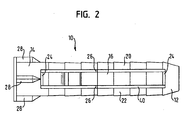
- a dowel 10 having a front end 12, a rear end 14 and four segments 16, 18, 20, 22, which connect the front end 12 and the rear end 14 together.
- the front end 12 is formed as a circumferentially closed, frusto-conical body.
- the rear end 14 is formed as also closed in the circumferential direction, sleeve-shaped body with collar.
- two segments 16, 18 are formed as rotational locking segments.
- the two other segments 20, 22 are formed as ceremoniesnpreß segments.
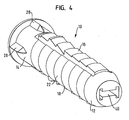
- the rotational locking segments 16, 18 have a plurality of teeth, which consist of a plurality of front, same teeth, some further protruding, middle teeth and a rear tooth.
- the anti-rotation segments 16 extend further beyond the outer periphery of the dowel defined by the forward end 12, the rearward end 14, and the land segments 20, 22.
- Each anti-rotation segment 16, 18 is connected to the front end 12 and the rear end 14 via spring bridges 24.
- the spring bridges are formed by cuts, so that only a thin material web remains between the rotational locking segment and the front end or the rear end.
- the spring bridges 24 make it possible for the rotational locking segments 16, 18 to yield elastically towards the interior of the anchor. Between adjacent segments small stiffening webs 26 are provided.
- Theêtnpreß segments 20, 22 are provided on its outer side with a nearly continuous smooth surface. There are only hinted to recognize some very flat teeth.
- the rear end 14 of the dowel is provided on its outer surface with a plurality of locking ribs 28. On its inside, the rear end 14 is provided with a plurality of abutment ribs 30.
- a screw channel 40 is formed, which is defined by substantially four flat surfaces. These surfaces are formed by the Inner sides of the segments 16, 18, 20, 22.
- the screw channel 40 has an H-shaped cross section.
- the screw channel 40 has in the region of the front end 12 and the segments 16, 18, 20, 22 throughout the same cross-section.
- the central web of the H-shaped cross-section is defined by the two rotational locking segments 16, 18, which face each other at a comparatively small distance.
- the two crossbars of the H-shaped cross section are defined by theinstitunpreß segments 20, 22. The distance between the inner surfaces of these segments is much greater than the distance between the inner surfaces of the rotational locking segments 16, 18th
- the nominal diameter of the anchor and thus also the diameter of the borehole provided for it is determined by the diameter, which is determined by the consultancynpreß segments 20, 22.
- the rotational locking segments 16, 18 are beyond the nominal diameter.
- the anti-rotation segments 16, 18, when in their home position define a diameter of the order of 11 to 12 mm.
- the anti-rotation segments 16, 18 spring back elastically. The necessary elasticity is ensured by the spring bridges 24.
- the rotational locking segments 16, 18 are by their elastic restoring forces on the inner wall of the borehole, so that is prevented by the resulting frictional forces that the dowel rotates when a screw is screwed.
- the locking ribs 28 act.
- a screw In order to insert a dowel into a borehole, a screw is often pressed into the dowel and then the dowel hammered into the borehole by means of the screw.
- the abutment lips 30 serve to resist the screw, so that they can not be pushed so far into the screw channel 40 that it prevents the elastic return springs of the rotational locking segments 16, 18.
- the screw If after the complete insertion of the anchor in the well, the screw is inserted further into the screw channel 40, the screw spreads the segments 16, 18, 20, 22 to the outside. Since the segments abut the screw with a flat surface, the screw can exert a very large spreading force on the segments; There is a lot of dowel material available for power transmission. Also, the screw is guided cleanly in the screw channel 40, since the straight Surfaces on the inside of the segments prevent the screw from slipping into the gap between individual segments.
Abstract
Description
Die Erfindung betrifft einen Dübel, insbesondere für Vollbaustoffe, gemäß dem Oberbegriff des Anspruchs 1.The invention relates to a dowel, in particular for solid building materials, according to the preamble of
Bei Dübeln für Vollbaustoffe (beispielsweise Beton) erfolgt die Verankerung des Dübels in der für seine Aufnahme vorgesehenen Bohrung im wesentlichen durch Flächenpressung zwischen der Außenseite des Dübels und der Innenwand der Bohrung. In einigen Fällen ergibt sich zusätzlich eine Verzahnungswirkung.For dowels for solid building materials (such as concrete), the anchorage of the anchor in the intended for its inclusion hole is carried out essentially by surface pressure between the outside of the dowel and the inner wall of the bore. In some cases, an additional gearing effect results.
Die bisher bekannten Dübel waren hinsichtlich der Auszugskräfte nicht immer zufriedenstellend, insbesondere wenn unterschiedliche Schrauben in sie eingeschraubt wurden.The previously known dowels were not always satisfactory in terms of pull-out forces, especially when different screws were screwed into them.
In der gattungsgemäßen
Eine ähnliche Gestaltung ist in der
Die
Die Aufgabe der Erfindung besteht darin, einen Dübel zu schaffen, der sich durch besonders hohe Auszugskräfte auszeichnet.The object of the invention is to provide a dowel, which is characterized by particularly high pull-out forces.
Zur Lösung dieser Aufgabe sind erfindungsgemäß die Merkmale des Anspruchs 1 vorgesehen. Die Erfindung beruht auf der Erkenntnis, daß die Ausgestaltung der Segmente, aus denen der Schaft des Dübels besteht, im Stand der Technik ausschlaggebend für eine Reihe von Problemen war. Die Freiräume zwischen den einzelnen Segmenten haben sich im Stand der Technik in radialer Richtung erstreckt, haben sich also in der Mitte getroffen. Die dadurch gebildeten Segmente haben im Querschnitt die Form von Tortenstücken, deren Spitzen einander zugewandt sind. Zwischen den Segmenten ist dadurch ein Schraubenkanal definiert, der von mehreren einander gegenüberliegenden Kanten abgegrenzt wird, nämlich von den Spitzen der "Tortenstücke". Wenn eine Schraube in diesen Schraubenkanal eingeschraubt wird, trifft sie auf vergleichsweise wenig Material. Insbesondere bei einer Spanplattenschraube, die sich durch einen vergleichsweise geringen Kerndurchmesser und ein scharfkantiges Gewinde auszeichnet, wird das Material der Segmente sehr leicht verdrängt, so daß die Schraube keine großen Spreizkräfte ausüben kann. Ein weiteres Problem besteht darin, daß einander in Abstand gegenüberliegende Kanten, die einen Schraubenkanal definieren, nur sehr schlecht zur Führung der Schraube geeignet sind. Der erfindungsgemäße Schraubenkanal wird anders als im Stand der Technik nicht von Kanten definiert, sondern von Flächen. Dies hat zum einen den Vorteil, daß einer einzuschraubenden Schraube eine sehr viel bessere Führung angeboten wird. Zum anderen ergibt sich der Vorteil, daß vergleichsweise viel Material zur Verfügung steht, welches von der Schraube verdrängt werden muß. Auf diese Weise werden höhere Spreizkräfte erzielt.To achieve this object, the features of
Der Schraubenkanal hat einen H-förmigen Querschnitt. Diese Form des Querschnitts kann besonders leicht mit mehreren beweglichen Schiebern in einer Spritzgußmaschine hergestellt werden, da die erforderlichen äußeren Schieber bündig auf dem mittleren Schieber aufliegen können.The screw channel has an H-shaped cross-section. This shape of the cross section can be made particularly easily with several movable slides in an injection molding machine, since the required outer slide can rest flush on the middle slide.
Gemäß einer Ausführungsform der Erfindung ist vorgesehen, daß zwei einander gegenüberliegende Segmente als Drehsperr-Segmente ausgebildet sind. Es ist nicht erforderlich, separate Flügel oder anderes vorzusehen, welches verhindert, daß sich der Dübel im Bohrloch mitdreht, wenn die Schraube eingeschraubt wird. Stattdessen ist es in einfacher Weise möglich, die Drehsperr-Segmente in radialer Richtung weiter nach außen ragen zu lassen als die dazwischenliegenden Segmente, so daß die Drehsperr-Segmente durch elastische Federkraft an der Wandung der Bohrung anliegen und ein Mitdrehen des Dübels verhindern.According to one embodiment of the invention, it is provided that two opposing segments are formed as rotational locking segments. It is not necessary to provide separate wings or other which prevents the dowel from rotating in the borehole when the screw is screwed in. Instead, it is possible in a simple manner, the rotational locking segments protrude in the radial direction to the outside than the intermediate segments, so that the rotational locking segments rest by elastic spring force on the wall of the bore and prevent turning of the anchor.
Vorteilhafte Ausgestaltungen der Erfindung ergeben sich aus den Unteransprüchen.Advantageous embodiments of the invention will become apparent from the dependent claims.
Die Erfindung wird nachfolgend anhand einer Ausführungsform erläutert, die in den beigefügten Zeichnungen dargestellt ist. In diesen zeigen:
-
Figur 1 -
Figur 2 eine Seitenansicht des erfindungsgemäßen Dübels; -
Figur 3 eine Vorderansicht des erfindungsgemäßen Dübels; -
Figur 4 eine weitere perspektivische Ansicht des erfindungsgemäßen Dübels; -
Figur 5 eine perspektivische Rückansicht des erfindungsgemäßen Dübels; -
Figur 6 einen Längsschnitt des erfindungsgemäßen Dübels; und -
Figur 7 einen zweiten Längsschnitt des Dübels, wobei die Schnittachse gegenüber dem Schnitt vonFigur 6 um 90° gedreht ist.
-
FIG. 1 a perspective view of a dowel according to the invention; -
FIG. 2 a side view of the anchor according to the invention; -
FIG. 3 a front view of the anchor according to the invention; -
FIG. 4 a further perspective view of the anchor according to the invention; -
FIG. 5 a perspective rear view of the anchor according to the invention; -
FIG. 6 a longitudinal section of the anchor according to the invention; and -
FIG. 7 a second longitudinal section of the dowel, wherein the cutting axis relative to the section ofFIG. 6 rotated by 90 °.
In den Figuren ist ein Dübel 10 gezeigt, der ein Vorderende 12, ein Hinterende 14 und vier Segmente 16, 18, 20, 22 aufweist, welche das Vorderende 12 und das Hinterende 14 miteinander verbinden. Das Vorderende 12 ist als in Umfangsrichtung geschlossener, kegelstumpfförmiger Körper ausgebildet. Das Hinterende 14 ist als ebenfalls in Umfangsrichtung geschlossener, hülsenförmiger Körper mit Bund ausgebildet. Von den Segmenten sind zwei Segmente 16, 18 als Drehsperr-Segmente ausgebildet. Die beiden anderen Segmente 20, 22 sind als Flächenpreß-Segmente ausgebildet.In the figures, a
Die Drehsperr-Segmente 16, 18 weisen mehrere Zähne auf, die aus mehreren vorderen, gleichen Zähnen, einigen weiter vorstehenden, mittleren Zähnen sowie einem hinteren Zahn bestehen. Die Drehsperr-Segmente 16 stehen weiter über den Außenumfang des Dübels hinaus, der vom Vorderende 12, dem Hinterende 14 und den Flächenpreß-Segmenten 20, 22 definiert wird. Jedes Drehsperr-Segment 16, 18 ist mit dem Vorderende 12 und dem Hinterende 14 über Federbrücken 24 verbunden. Die Federbrücken sind gebildet durch Einschnitte, so daß zwischen dem Drehsperr-Segment und dem Vorderende bzw. dem Hinterende nur ein dünner Materialsteg stehen bleibt. Die Federbrücken 24 ermöglichen es den Drehsperr-Segmenten 16, 18, elastisch zum Inneren des Dübels hin nachzugeben. Zwischen benachbarten Segmenten sind kleine Versteifungsstege 26 vorgesehen.The
Die Flächenpreß-Segmente 20, 22 sind auf ihrer Außenseite mit einer nahezu durchgehend glatten Fläche versehen. Es sind lediglich andeutungsweise einige sehr flache Zähne zu erkennen.The
Das Hinterende 14 des Dübels ist auf seiner Außenfläche mit mehreren Sperr-Rippen 28 versehen. Auf seiner Innenseite ist das Hinterende 14 mit mehreren Anlagerippen 30 versehen.The
Im Inneren des Dübels ist ein Schraubenkanal 40 gebildet, der definiert wird durch im wesentlichen vier ebene Flächen. Diese Flächen sind gebildet durch die Innenseiten der Segmente 16, 18, 20, 22. Wie insbesondere in
Der Nenndurchmesser des Dübels und damit auch der Durchmesser des für ihn vorgesehenen Bohrlochs ist bestimmt durch den Durchmesser, der von den Flächenpreß-Segmenten 20, 22 bestimmt ist. Die Drehsperr-Segmente 16, 18 stehen über den Nenndurchmesser hinaus. Bei einem Nenndurchmesser des Dübels von 10 mm definieren die Drehsperr-Segmente 16, 18, wenn sie sich in ihrer Ausgangsstellung befinden, einen Durchmesser in der Größenordnung von 11 bis 12 mm.The nominal diameter of the anchor and thus also the diameter of the borehole provided for it is determined by the diameter, which is determined by the
Wenn der Dübel in ein Bohrloch mit seinem Nenndurchmesser eingesetzt wird, federn die Drehsperr-Segmente 16, 18 elastisch nach innen zurück. Die hierfür notwendige Elastizität wird von den Federbrücken 24 gewährleistet. Wenn der Dübel ins Bohrloch eingeschoben ist, liegen die Drehsperr-Segmente 16, 18 durch ihre elastischen Rückstellkräfte an der Innenwand des Bohrlochs an, so daß durch die sich ergebenden Reibungskräfte verhindert ist, daß sich der Dübel mitdreht, wenn eine Schraube eingeschraubt wird. Ergänzend wirken die Sperr-Rippen 28.When the dowel is inserted into a nominal diameter borehole, the
Um einen Dübel in ein Bohrloch einzusetzen, wird häufig eine Schraube in den Dübel hineingedrückt und dann der Dübel mittels der Schraube in das Bohrloch eingeschlagen. Bei dem beschriebenen Dübel dienen die Anlagerippen 30 dafür, der Schraube einen Widerstand entgegenzusetzen, damit diese nicht so weit in den Schraubenkanal 40 eingeschoben werden kann, daß sie das elastische Rückfedern der Drehsperr-Segmente 16, 18 verhindert. Wenn nach dem vollständigen Einsetzen des Dübels in das Bohrloch die Schraube weiter in den Schraubenkanal 40 eingeschoben wird, spreizt die Schraube die Segmente 16, 18, 20, 22 nach außen. Da die Segmente an der Schraube mit einer ebenen Fläche anliegen, kann die Schraube eine sehr große Spreizkraft auf die Segmente ausüben; es steht sehr viel Dübelmaterial zur Kraftübertragung zur Verfügung. Auch wird die Schraube sauber im Schraubenkanal 40 geführt, da die geraden Flächen auf der Innenseite der Segmente verhindern, daß die Schraube in den Spalt zwischen einzelne Segmente rutscht.In order to insert a dowel into a borehole, a screw is often pressed into the dowel and then the dowel hammered into the borehole by means of the screw. In the dowel described the
Claims (9)
- A plug (10), in particular for solid building materials, having a shank composed of four segments (16, 18, 20, 22) which are arranged opposite each other in pairs and define a screw channel (40) delimited by faces, characterized in that the screw channel (40) has an H-shaped cross-section.
- The plug according to claim 1, characterized in that the faces defining the screw channel (40) are flat.
- The plug according to any of the preceding claims, characterized in that two segments (20, 22) that are opposite each other are configured as surface pressing segments having a flat or at least approximately flat outer surface.
- The plug according to any of the preceding claims, characterized in that two segments (16, 18) that are opposite each other are configured as toothed segments the outer surface of which is provided with several teeth.
- The plug according to any of the preceding claims, characterized in that two segments that are opposite each other are configured as rotation locking segments (16, 18).
- The plug according to claim 5, characterized in that the two rotation locking segments (16, 18) project further outwards in the radial direction than the segments arranged therebetween.
- The plug according to claim 5 or claim 6, characterized in that the outside of the rotation locking segments (16, 18) is provided with teeth.
- The plug according to any of claims 5 to 7, characterized in that the rotation locking segments (16, 18) are elastically resilient in the radial direction.
- The plug according to claim 8, characterized in that the rotation locking segments (16, 18) are connected by means of spring bridges (24).
Priority Applications (2)
| Application Number | Priority Date | Filing Date | Title |
|---|---|---|---|
| PL06023014T PL1783380T3 (en) | 2005-11-08 | 2006-11-06 | Dowel, especially for building materials |
| SI200630123T SI1783380T1 (en) | 2005-11-08 | 2006-11-06 | Dowel, especially for building materials |
Applications Claiming Priority (1)
| Application Number | Priority Date | Filing Date | Title |
|---|---|---|---|
| DE202005017435U DE202005017435U1 (en) | 2005-11-08 | 2005-11-08 | Dowels, in particular for solid building materials |
Publications (2)
| Publication Number | Publication Date |
|---|---|
| EP1783380A1 EP1783380A1 (en) | 2007-05-09 |
| EP1783380B1 true EP1783380B1 (en) | 2008-09-17 |
Family
ID=36121054
Family Applications (1)
| Application Number | Title | Priority Date | Filing Date |
|---|---|---|---|
| EP06023014A Not-in-force EP1783380B1 (en) | 2005-11-08 | 2006-11-06 | Dowel, especially for building materials |
Country Status (8)
| Country | Link |
|---|---|
| EP (1) | EP1783380B1 (en) |
| AT (1) | ATE408761T1 (en) |
| DE (2) | DE202005017435U1 (en) |
| DK (1) | DK1783380T3 (en) |
| ES (1) | ES2314808T3 (en) |
| PL (1) | PL1783380T3 (en) |
| PT (1) | PT1783380E (en) |
| SI (1) | SI1783380T1 (en) |
Families Citing this family (5)
| Publication number | Priority date | Publication date | Assignee | Title |
|---|---|---|---|---|
| DE202005020063U1 (en) * | 2005-12-22 | 2006-04-06 | Berner Gmbh | impact anchors |
| DE102007051629B4 (en) * | 2007-10-26 | 2014-02-13 | Günther Zimmer | Dowels with structured clamping section |
| DE102010026994A1 (en) * | 2010-07-13 | 2012-01-19 | Trw Automotive Electronics & Components Gmbh | Holding dowel for fastening trim panel to body part of vehicle, has anchoring bars defining receptacle for spreader and molded seal, where anchoring bars include anchoring elements arranged in radial direction to receptacle |
| DE102010026995A1 (en) * | 2010-07-13 | 2012-01-19 | Trw Automotive Electronics & Components Gmbh | Holding dowel for use in fastening assembly for fixing trim panel to body part of vehicle, has anchoring elements that are resiliently arranged in radial direction around receptacle, where anchoring elements are arc-shaped |
| ITUD20130077A1 (en) * | 2013-05-29 | 2014-11-30 | Friulsider S P A | EXPANSION FASTENER |
Family Cites Families (5)
| Publication number | Priority date | Publication date | Assignee | Title |
|---|---|---|---|---|
| DE2231809C2 (en) * | 1972-06-29 | 1974-05-22 | F. & G. Hachtel, 7080 Aalen | Expansion anchor made of plastic |
| FR2657926B1 (en) * | 1990-02-07 | 1992-05-29 | Comet | IMPROVEMENTS ON NUT CAGES FOR BLIND TYPE FASTENERS. |
| DE4205195A1 (en) * | 1991-02-20 | 1992-08-27 | Iobb Produktideen Vorausentwic | DUEBEL |
| DE9305762U1 (en) * | 1993-04-16 | 1993-06-17 | Dausend, Hans-Werner, 5600 Wuppertal, De | |
| DE202004019778U1 (en) * | 2004-12-22 | 2005-03-24 | Berner Gmbh | dowel |
-
2005
- 2005-11-08 DE DE202005017435U patent/DE202005017435U1/en not_active Expired - Lifetime
-
2006
- 2006-11-06 DE DE502006001589T patent/DE502006001589D1/en active Active
- 2006-11-06 DK DK06023014T patent/DK1783380T3/en active
- 2006-11-06 PT PT06023014T patent/PT1783380E/en unknown
- 2006-11-06 ES ES06023014T patent/ES2314808T3/en active Active
- 2006-11-06 AT AT06023014T patent/ATE408761T1/en active
- 2006-11-06 SI SI200630123T patent/SI1783380T1/en unknown
- 2006-11-06 PL PL06023014T patent/PL1783380T3/en unknown
- 2006-11-06 EP EP06023014A patent/EP1783380B1/en not_active Not-in-force
Also Published As
| Publication number | Publication date |
|---|---|
| ATE408761T1 (en) | 2008-10-15 |
| DE502006001589D1 (en) | 2008-10-30 |
| PL1783380T3 (en) | 2009-03-31 |
| DE202005017435U1 (en) | 2006-03-16 |
| SI1783380T1 (en) | 2009-02-28 |
| ES2314808T3 (en) | 2009-03-16 |
| EP1783380A1 (en) | 2007-05-09 |
| PT1783380E (en) | 2008-12-09 |
| DK1783380T3 (en) | 2009-01-26 |
Similar Documents
| Publication | Publication Date | Title |
|---|---|---|
| EP2943090B1 (en) | Glueless composite panel and method for the glueless connection of two panel elements | |
| EP0169335B1 (en) | Plug | |
| DE10065398A1 (en) | Length-adjustable placeholder for insertion between two vertebrae | |
| EP1783380B1 (en) | Dowel, especially for building materials | |
| DE2901066B1 (en) | Expansion anchor | |
| DE2947752C2 (en) | ||
| EP1674738B1 (en) | Allround dowel | |
| DE59703501C5 (en) | expansion anchor | |
| DE102005034928A1 (en) | Square pin for a door button comprises recesses distributed on its end regions for receiving a fixing element which enlarges the periphery of the pin | |
| DE1288367B (en) | Cylindrical plastic dowel | |
| DE2627650A1 (en) | FASTENING KIT WITH EXPANDING PLUG AND FIXING SCREW | |
| WO2005075310A1 (en) | Profile closing clip | |
| AT524670B1 (en) | Dowel for connecting two components | |
| EP0984119B1 (en) | Spring spindle, in particular a square-spindle for a handle | |
| EP2565470B1 (en) | Dowel | |
| DE3518866C1 (en) | Bolt parts for forming a self-locking blocking bolt | |
| EP0760429A1 (en) | Expansion dowel made of plastic | |
| EP1150058B1 (en) | Insulation element for a pipe elbow | |
| DE3909010C2 (en) | Plastic expansion anchors | |
| DE4014709C2 (en) | ||
| DE2302157C3 (en) | Expansion dowel for fastening objects to walls made of soft stone | |
| DE2200672A1 (en) | Delay cylinder | |
| EP3973197A1 (en) | Corner fitting | |
| EP1159535B1 (en) | Expansion dowel | |
| DE1400825C (en) | Expansion anchor |
Legal Events
| Date | Code | Title | Description |
|---|---|---|---|
| PUAI | Public reference made under article 153(3) epc to a published international application that has entered the european phase |
Free format text: ORIGINAL CODE: 0009012 |
|
| AK | Designated contracting states |
Kind code of ref document: A1 Designated state(s): AT BE BG CH CY CZ DE DK EE ES FI FR GB GR HU IE IS IT LI LT LU LV MC NL PL PT RO SE SI SK TR |
|
| AX | Request for extension of the european patent |
Extension state: AL BA HR MK YU |
|
| 17P | Request for examination filed |
Effective date: 20071031 |
|
| AKX | Designation fees paid |
Designated state(s): AT BE BG CH CY CZ DE DK EE ES FI FR GB GR HU IE IS IT LI LT LU LV MC NL PL PT RO SE SI SK TR |
|
| GRAP | Despatch of communication of intention to grant a patent |
Free format text: ORIGINAL CODE: EPIDOSNIGR1 |
|
| GRAS | Grant fee paid |
Free format text: ORIGINAL CODE: EPIDOSNIGR3 |
|
| GRAA | (expected) grant |
Free format text: ORIGINAL CODE: 0009210 |
|
| AK | Designated contracting states |
Kind code of ref document: B1 Designated state(s): AT BE BG CH CY CZ DE DK EE ES FI FR GB GR HU IE IS IT LI LT LU LV MC NL PL PT RO SE SI SK TR |
|
| REG | Reference to a national code |
Ref country code: GB Ref legal event code: FG4D Free format text: NOT ENGLISH |
|
| REG | Reference to a national code |
Ref country code: CH Ref legal event code: EP |
|
| REG | Reference to a national code |
Ref country code: IE Ref legal event code: FG4D Free format text: LANGUAGE OF EP DOCUMENT: GERMAN |
|
| REF | Corresponds to: |
Ref document number: 502006001589 Country of ref document: DE Date of ref document: 20081030 Kind code of ref document: P |
|
| REG | Reference to a national code |
Ref country code: CH Ref legal event code: NV Representative=s name: BUGNION S.A. |
|
| REG | Reference to a national code |
Ref country code: PT Ref legal event code: SC4A Free format text: AVAILABILITY OF NATIONAL TRANSLATION Effective date: 20081124 |
|
| REG | Reference to a national code |
Ref country code: SE Ref legal event code: TRGR |
|
| REG | Reference to a national code |
Ref country code: DK Ref legal event code: T3 |
|
| PG25 | Lapsed in a contracting state [announced via postgrant information from national office to epo] |
Ref country code: LT Free format text: LAPSE BECAUSE OF FAILURE TO SUBMIT A TRANSLATION OF THE DESCRIPTION OR TO PAY THE FEE WITHIN THE PRESCRIBED TIME-LIMIT Effective date: 20080917 |
|
| PGFP | Annual fee paid to national office [announced via postgrant information from national office to epo] |
Ref country code: DK Payment date: 20081118 Year of fee payment: 3 Ref country code: LU Payment date: 20081127 Year of fee payment: 3 |
|
| PG25 | Lapsed in a contracting state [announced via postgrant information from national office to epo] |
Ref country code: LV Free format text: LAPSE BECAUSE OF FAILURE TO SUBMIT A TRANSLATION OF THE DESCRIPTION OR TO PAY THE FEE WITHIN THE PRESCRIBED TIME-LIMIT Effective date: 20080917 |
|
| PGFP | Annual fee paid to national office [announced via postgrant information from national office to epo] |
Ref country code: ES Payment date: 20081121 Year of fee payment: 3 Ref country code: FI Payment date: 20081114 Year of fee payment: 3 |
|
| REG | Reference to a national code |
Ref country code: ES Ref legal event code: FG2A Ref document number: 2314808 Country of ref document: ES Kind code of ref document: T3 |
|
| PGFP | Annual fee paid to national office [announced via postgrant information from national office to epo] |
Ref country code: SE Payment date: 20081114 Year of fee payment: 3 |
|
| REG | Reference to a national code |
Ref country code: PL Ref legal event code: T3 |
|
| REG | Reference to a national code |
Ref country code: IE Ref legal event code: FD4D |
|
| PG25 | Lapsed in a contracting state [announced via postgrant information from national office to epo] |
Ref country code: BG Free format text: LAPSE BECAUSE OF FAILURE TO SUBMIT A TRANSLATION OF THE DESCRIPTION OR TO PAY THE FEE WITHIN THE PRESCRIBED TIME-LIMIT Effective date: 20081217 |
|
| PGFP | Annual fee paid to national office [announced via postgrant information from national office to epo] |
Ref country code: HU Payment date: 20081119 Year of fee payment: 3 |
|
| PG25 | Lapsed in a contracting state [announced via postgrant information from national office to epo] |
Ref country code: CZ Free format text: LAPSE BECAUSE OF FAILURE TO SUBMIT A TRANSLATION OF THE DESCRIPTION OR TO PAY THE FEE WITHIN THE PRESCRIBED TIME-LIMIT Effective date: 20080917 Ref country code: IS Free format text: LAPSE BECAUSE OF FAILURE TO SUBMIT A TRANSLATION OF THE DESCRIPTION OR TO PAY THE FEE WITHIN THE PRESCRIBED TIME-LIMIT Effective date: 20090117 Ref country code: RO Free format text: LAPSE BECAUSE OF FAILURE TO SUBMIT A TRANSLATION OF THE DESCRIPTION OR TO PAY THE FEE WITHIN THE PRESCRIBED TIME-LIMIT Effective date: 20080917 |
|
| PGFP | Annual fee paid to national office [announced via postgrant information from national office to epo] |
Ref country code: PL Payment date: 20081106 Year of fee payment: 3 Ref country code: PT Payment date: 20090203 Year of fee payment: 3 Ref country code: SK Payment date: 20081106 Year of fee payment: 3 |
|
| PG25 | Lapsed in a contracting state [announced via postgrant information from national office to epo] |
Ref country code: MC Free format text: LAPSE BECAUSE OF NON-PAYMENT OF DUE FEES Effective date: 20081130 |
|
| PGFP | Annual fee paid to national office [announced via postgrant information from national office to epo] |
Ref country code: SI Payment date: 20081112 Year of fee payment: 3 |
|
| PLBE | No opposition filed within time limit |
Free format text: ORIGINAL CODE: 0009261 |
|
| STAA | Information on the status of an ep patent application or granted ep patent |
Free format text: STATUS: NO OPPOSITION FILED WITHIN TIME LIMIT |
|
| PG25 | Lapsed in a contracting state [announced via postgrant information from national office to epo] |
Ref country code: EE Free format text: LAPSE BECAUSE OF FAILURE TO SUBMIT A TRANSLATION OF THE DESCRIPTION OR TO PAY THE FEE WITHIN THE PRESCRIBED TIME-LIMIT Effective date: 20080917 Ref country code: IE Free format text: LAPSE BECAUSE OF FAILURE TO SUBMIT A TRANSLATION OF THE DESCRIPTION OR TO PAY THE FEE WITHIN THE PRESCRIBED TIME-LIMIT Effective date: 20080917 |
|
| PGFP | Annual fee paid to national office [announced via postgrant information from national office to epo] |
Ref country code: BE Payment date: 20090126 Year of fee payment: 3 |
|
| 26N | No opposition filed |
Effective date: 20090618 |
|
| PGFP | Annual fee paid to national office [announced via postgrant information from national office to epo] |
Ref country code: AT Payment date: 20091113 Year of fee payment: 4 |
|
| PGFP | Annual fee paid to national office [announced via postgrant information from national office to epo] |
Ref country code: NL Payment date: 20091112 Year of fee payment: 4 |
|
| REG | Reference to a national code |
Ref country code: PT Ref legal event code: MM4A Free format text: LAPSE DUE TO NON-PAYMENT OF FEES Effective date: 20100506 |
|
| BERE | Be: lapsed |
Owner name: BERNER G.M.B.H. Effective date: 20091130 |
|
| EUG | Se: european patent has lapsed | ||
| REG | Reference to a national code |
Ref country code: DK Ref legal event code: EBP |
|
| PG25 | Lapsed in a contracting state [announced via postgrant information from national office to epo] |
Ref country code: HU Free format text: LAPSE BECAUSE OF NON-PAYMENT OF DUE FEES Effective date: 20091107 Ref country code: CY Free format text: LAPSE BECAUSE OF FAILURE TO SUBMIT A TRANSLATION OF THE DESCRIPTION OR TO PAY THE FEE WITHIN THE PRESCRIBED TIME-LIMIT Effective date: 20080917 Ref country code: PT Free format text: LAPSE BECAUSE OF NON-PAYMENT OF DUE FEES Effective date: 20100506 |
|
| REG | Reference to a national code |
Ref country code: SI Ref legal event code: KO00 Effective date: 20100615 |
|
| REG | Reference to a national code |
Ref country code: SK Ref legal event code: MM4A Ref document number: E 4556 Country of ref document: SK Effective date: 20091106 |
|
| PG25 | Lapsed in a contracting state [announced via postgrant information from national office to epo] |
Ref country code: SI Free format text: LAPSE BECAUSE OF NON-PAYMENT OF DUE FEES Effective date: 20091107 Ref country code: FI Free format text: LAPSE BECAUSE OF NON-PAYMENT OF DUE FEES Effective date: 20091106 Ref country code: SK Free format text: LAPSE BECAUSE OF NON-PAYMENT OF DUE FEES Effective date: 20091106 |
|
| PG25 | Lapsed in a contracting state [announced via postgrant information from national office to epo] |
Ref country code: BE Free format text: LAPSE BECAUSE OF NON-PAYMENT OF DUE FEES Effective date: 20091130 Ref country code: GR Free format text: LAPSE BECAUSE OF FAILURE TO SUBMIT A TRANSLATION OF THE DESCRIPTION OR TO PAY THE FEE WITHIN THE PRESCRIBED TIME-LIMIT Effective date: 20081218 |
|
| PG25 | Lapsed in a contracting state [announced via postgrant information from national office to epo] |
Ref country code: DK Free format text: LAPSE BECAUSE OF NON-PAYMENT OF DUE FEES Effective date: 20091130 |
|
| REG | Reference to a national code |
Ref country code: ES Ref legal event code: FD2A Effective date: 20110302 |
|
| PG25 | Lapsed in a contracting state [announced via postgrant information from national office to epo] |
Ref country code: LU Free format text: LAPSE BECAUSE OF NON-PAYMENT OF DUE FEES Effective date: 20091106 |
|
| PG25 | Lapsed in a contracting state [announced via postgrant information from national office to epo] |
Ref country code: PL Free format text: LAPSE BECAUSE OF NON-PAYMENT OF DUE FEES Effective date: 20091106 Ref country code: SE Free format text: LAPSE BECAUSE OF NON-PAYMENT OF DUE FEES Effective date: 20091107 |
|
| REG | Reference to a national code |
Ref country code: NL Ref legal event code: V1 Effective date: 20110601 |
|
| REG | Reference to a national code |
Ref country code: CH Ref legal event code: PL Ref country code: PL Ref legal event code: LAPE |
|
| GBPC | Gb: european patent ceased through non-payment of renewal fee |
Effective date: 20101106 |
|
| PG25 | Lapsed in a contracting state [announced via postgrant information from national office to epo] |
Ref country code: ES Free format text: LAPSE BECAUSE OF NON-PAYMENT OF DUE FEES Effective date: 20110301 Ref country code: CH Free format text: LAPSE BECAUSE OF NON-PAYMENT OF DUE FEES Effective date: 20101130 Ref country code: LI Free format text: LAPSE BECAUSE OF NON-PAYMENT OF DUE FEES Effective date: 20101130 |
|
| PG25 | Lapsed in a contracting state [announced via postgrant information from national office to epo] |
Ref country code: NL Free format text: LAPSE BECAUSE OF NON-PAYMENT OF DUE FEES Effective date: 20110601 |
|
| PG25 | Lapsed in a contracting state [announced via postgrant information from national office to epo] |
Ref country code: ES Free format text: LAPSE BECAUSE OF NON-PAYMENT OF DUE FEES Effective date: 20091107 |
|
| PGFP | Annual fee paid to national office [announced via postgrant information from national office to epo] |
Ref country code: TR Payment date: 20081113 Year of fee payment: 3 |
|
| PG25 | Lapsed in a contracting state [announced via postgrant information from national office to epo] |
Ref country code: GB Free format text: LAPSE BECAUSE OF NON-PAYMENT OF DUE FEES Effective date: 20101106 |
|
| REG | Reference to a national code |
Ref country code: DE Ref legal event code: R082 Ref document number: 502006001589 Country of ref document: DE Representative=s name: PRINZ & PARTNER PATENTANWAELTE RECHTSANWAELTE, DE |
|
| REG | Reference to a national code |
Ref country code: DE Ref legal event code: R081 Ref document number: 502006001589 Country of ref document: DE Owner name: BERNER TRADING HOLDING GMBH, DE Free format text: FORMER OWNER: BERNER GMBH, 74653 KUENZELSAU, DE Effective date: 20120215 Ref country code: DE Ref legal event code: R082 Ref document number: 502006001589 Country of ref document: DE Representative=s name: PRINZ & PARTNER MBB PATENTANWAELTE RECHTSANWAE, DE Effective date: 20120215 |
|
| REG | Reference to a national code |
Ref country code: FR Ref legal event code: CJ Effective date: 20121011 Ref country code: FR Ref legal event code: TP Owner name: BERNER TRADING HOLDING GMBH, DE Effective date: 20121011 |
|
| REG | Reference to a national code |
Ref country code: AT Ref legal event code: MM01 Ref document number: 408761 Country of ref document: AT Kind code of ref document: T Effective date: 20111106 |
|
| PG25 | Lapsed in a contracting state [announced via postgrant information from national office to epo] |
Ref country code: AT Free format text: LAPSE BECAUSE OF NON-PAYMENT OF DUE FEES Effective date: 20111106 Ref country code: TR Free format text: LAPSE BECAUSE OF NON-PAYMENT OF DUE FEES Effective date: 20091106 |
|
| PGFP | Annual fee paid to national office [announced via postgrant information from national office to epo] |
Ref country code: FR Payment date: 20131128 Year of fee payment: 8 Ref country code: IT Payment date: 20131129 Year of fee payment: 8 |
|
| REG | Reference to a national code |
Ref country code: FR Ref legal event code: ST Effective date: 20150731 |
|
| PG25 | Lapsed in a contracting state [announced via postgrant information from national office to epo] |
Ref country code: FR Free format text: LAPSE BECAUSE OF NON-PAYMENT OF DUE FEES Effective date: 20141201 |
|
| PG25 | Lapsed in a contracting state [announced via postgrant information from national office to epo] |
Ref country code: IT Free format text: LAPSE BECAUSE OF NON-PAYMENT OF DUE FEES Effective date: 20141106 |
|
| PGFP | Annual fee paid to national office [announced via postgrant information from national office to epo] |
Ref country code: DE Payment date: 20151126 Year of fee payment: 10 |
|
| REG | Reference to a national code |
Ref country code: DE Ref legal event code: R119 Ref document number: 502006001589 Country of ref document: DE |
|
| PG25 | Lapsed in a contracting state [announced via postgrant information from national office to epo] |
Ref country code: DE Free format text: LAPSE BECAUSE OF NON-PAYMENT OF DUE FEES Effective date: 20170601 |