EP2942562A2 - Belüftungssystem für fahrzeugbeleuchtungen - Google Patents
Belüftungssystem für fahrzeugbeleuchtungen Download PDFInfo
- Publication number
- EP2942562A2 EP2942562A2 EP15165860.6A EP15165860A EP2942562A2 EP 2942562 A2 EP2942562 A2 EP 2942562A2 EP 15165860 A EP15165860 A EP 15165860A EP 2942562 A2 EP2942562 A2 EP 2942562A2
- Authority
- EP
- European Patent Office
- Prior art keywords
- ventilation
- opening
- housing opening
- wall
- housing
- Prior art date
- Legal status (The legal status is an assumption and is not a legal conclusion. Google has not performed a legal analysis and makes no representation as to the accuracy of the status listed.)
- Granted
Links
Images

Classifications
-
- F—MECHANICAL ENGINEERING; LIGHTING; HEATING; WEAPONS; BLASTING
- F21—LIGHTING
- F21S—NON-PORTABLE LIGHTING DEVICES; SYSTEMS THEREOF; VEHICLE LIGHTING DEVICES SPECIALLY ADAPTED FOR VEHICLE EXTERIORS
- F21S45/00—Arrangements within vehicle lighting devices specially adapted for vehicle exteriors, for purposes other than emission or distribution of light
- F21S45/40—Cooling of lighting devices
- F21S45/47—Passive cooling, e.g. using fins, thermal conductive elements or openings
-
- F—MECHANICAL ENGINEERING; LIGHTING; HEATING; WEAPONS; BLASTING
- F21—LIGHTING
- F21S—NON-PORTABLE LIGHTING DEVICES; SYSTEMS THEREOF; VEHICLE LIGHTING DEVICES SPECIALLY ADAPTED FOR VEHICLE EXTERIORS
- F21S45/00—Arrangements within vehicle lighting devices specially adapted for vehicle exteriors, for purposes other than emission or distribution of light
- F21S45/30—Ventilation or drainage of lighting devices
- F21S45/37—Ventilation or drainage of lighting devices specially adapted for signal lamps
-
- F—MECHANICAL ENGINEERING; LIGHTING; HEATING; WEAPONS; BLASTING
- F21—LIGHTING
- F21S—NON-PORTABLE LIGHTING DEVICES; SYSTEMS THEREOF; VEHICLE LIGHTING DEVICES SPECIALLY ADAPTED FOR VEHICLE EXTERIORS
- F21S45/00—Arrangements within vehicle lighting devices specially adapted for vehicle exteriors, for purposes other than emission or distribution of light
- F21S45/30—Ventilation or drainage of lighting devices
-
- F—MECHANICAL ENGINEERING; LIGHTING; HEATING; WEAPONS; BLASTING
- F21—LIGHTING
- F21S—NON-PORTABLE LIGHTING DEVICES; SYSTEMS THEREOF; VEHICLE LIGHTING DEVICES SPECIALLY ADAPTED FOR VEHICLE EXTERIORS
- F21S45/00—Arrangements within vehicle lighting devices specially adapted for vehicle exteriors, for purposes other than emission or distribution of light
- F21S45/30—Ventilation or drainage of lighting devices
- F21S45/33—Ventilation or drainage of lighting devices specially adapted for headlamps
-
- F—MECHANICAL ENGINEERING; LIGHTING; HEATING; WEAPONS; BLASTING
- F21—LIGHTING
- F21V—FUNCTIONAL FEATURES OR DETAILS OF LIGHTING DEVICES OR SYSTEMS THEREOF; STRUCTURAL COMBINATIONS OF LIGHTING DEVICES WITH OTHER ARTICLES, NOT OTHERWISE PROVIDED FOR
- F21V29/00—Protecting lighting devices from thermal damage; Cooling or heating arrangements specially adapted for lighting devices or systems
- F21V29/50—Cooling arrangements
- F21V29/70—Cooling arrangements characterised by passive heat-dissipating elements, e.g. heat-sinks
- F21V29/83—Cooling arrangements characterised by passive heat-dissipating elements, e.g. heat-sinks the elements having apertures, ducts or channels, e.g. heat radiation holes
-
- F—MECHANICAL ENGINEERING; LIGHTING; HEATING; WEAPONS; BLASTING
- F21—LIGHTING
- F21W—INDEXING SCHEME ASSOCIATED WITH SUBCLASSES F21K, F21L, F21S and F21V, RELATING TO USES OR APPLICATIONS OF LIGHTING DEVICES OR SYSTEMS
- F21W2102/00—Exterior vehicle lighting devices for illuminating purposes
-
- F—MECHANICAL ENGINEERING; LIGHTING; HEATING; WEAPONS; BLASTING
- F21—LIGHTING
- F21W—INDEXING SCHEME ASSOCIATED WITH SUBCLASSES F21K, F21L, F21S and F21V, RELATING TO USES OR APPLICATIONS OF LIGHTING DEVICES OR SYSTEMS
- F21W2103/00—Exterior vehicle lighting devices for signalling purposes
- F21W2103/20—Direction indicator lights
-
- F—MECHANICAL ENGINEERING; LIGHTING; HEATING; WEAPONS; BLASTING
- F21—LIGHTING
- F21W—INDEXING SCHEME ASSOCIATED WITH SUBCLASSES F21K, F21L, F21S and F21V, RELATING TO USES OR APPLICATIONS OF LIGHTING DEVICES OR SYSTEMS
- F21W2107/00—Use or application of lighting devices on or in particular types of vehicles
- F21W2107/10—Use or application of lighting devices on or in particular types of vehicles for land vehicles
Definitions
- a ventilation system for vehicle lights is known in which the ventilation system is provided at a rear side of a housing. At the housing opening of the housing a plurality of outwardly projecting walls of different height are provided, on which a cap-shaped ventilation body can be placed. A labyrinth-like ventilation channel is formed. The cap-shaped ventilation body is latchingly connected to walls of the housing opening, wherein the cap-shaped ventilation body to obtain the fixing position in the axial direction is placed on the walls of the housing opening.
- a ventilation system for vehicle lighting with a housing in which a cap-shaped ventilation body is placed in the axial direction on a housing opening and latched with this fixed.
- the ventilation body and the housing opening have walls, so that a ventilation channel with a plurality of deflections between an edge of the ventilation body and an opening of the housing opening is formed.
- the fixation of the ventilation body by means of a locking element which engages in the opening of the housing opening.
- the fixation is effected by axial snap-locking of the locking element in the opening of the housing opening, wherein barb-shaped ends of the locking element engage behind a wall of the housing.
- Object of the present invention is to develop a ventilation system such that a simple installation and a secure fixation is made possible, which ensures a high degree of sealing and variable use.
- a ventilation body on the one hand in the housing opening projecting inner part and on the other an opening wall of the housing opening surrounding the outer part, which take over the housing opening sealing function with their walls.
- the ventilation body is designed as a rotary closure, so that the fixation takes place by rotation of the ventilation body relative to the housing opening about an axis thereof.
- the opening wall of the housing opening is formed in two stages.
- a breakthrough of the housing opening is limited by a high opening wall whose free edge forms a relatively large distance from a housing wall running perpendicular to the axis of the housing opening.
- a low opening wall is provided at a radial distance from the high opening wall, whose free edge has a relatively small distance from the housing wall.
- the high opening wall essentially serves to rest the inner part on an inner side thereof.
- the high opening wall locking elements for fixing the inner part in the locking position on the housing opening.
- the low opening wall serves to seal the system of the outer part.
- the low opening wall has a recess in regions, a passage for one end of the ventilation duct can be formed there, with a first deflection of the ventilation duct.
- the low opening wall and the outer part allow an arcuate course of the ventilation duct, wherein the ventilation duct is divided at the recess of the opening wall into two arcuate ventilation duct sections.
- the inner part or the high opening wall is thereby flowed around in the circumferential direction, until on an opposite side of the recess to the recess, an axial ventilation duct section is reached, which extends between the high opening wall and the inner part.
- a second deflection of the ventilation duct is provided.
- a labyrinth-like ventilation channel is thereby formed, wherein at the same time the ventilation body is sealingly fixed to the housing opening.
- the inner part of the ventilation body and the high opening wall on a rear locking elements which allows a positive and / or non-positive locking of the ventilation body to the housing wall by rotation of the ventilation body about an axis of the housing opening.
- this ensures a secure bayonet-like fixation, wherein the ventilation body occupies a defined mounting position in the locking position to the housing opening.
- the locking element of the inner part of the ventilation body is radially projecting, so that it engages in the locking position an arc portion of the arranged at the back of the high opening wall locking element detent. In this way, an axial holding force can be exercised, which holds the ventilation body sealing and positionally secure in the locking position.
- a bottom-side edge of the high opening wall is contoured such that only one type of aeration bodies of a plurality of different types of ventilation bodies can be brought into the locking position.
- a "hard coding" is created which allows compatibility of the housing opening also, for example, to each provided with a membrane ventilation bodies.
- the ventilation body has a corresponding to the recess of the low opening wall radial projection on the outer part of the ventilation body.
- one end of the ventilation duct is defined on one side of the ventilation body, wherein this end is preferably arranged in a vertically lower region of the ventilation system.
- the unwanted ingress of liquids into the housing can be avoided in this way.
- the inner part has a foot section, which is arranged only on one of the radial projection facing half side.
- a radial surface of the foot section serves as a contact surface on an inner side of the high opening wall.
- the inner part On one side facing away from the radial projection, the inner part has a recess or a deflection web, so that an axial section of the ventilation channel is formed, which extends from the free edge of the opening wall to a bottom plane of the opening wall.
- the inner part is formed flattened in an adjoining the foot portion extension section, the axial portion of the ventilation channel can form in the locking position of the ventilation body.
- the housing opening has a mounting frame arranged at a radial distance from the high opening wall and the low opening wall, the radius of which is greater only in a rotation angle range of the ventilation body than a radius of the radial projection of the ventilation body.
- a defined insertion position of the ventilation body is defined in the non-locking position or the rotation of the ventilation body from the Tinarretierlage in the locking position and vice versa.
- the assembly can be facilitated thereby.
- the mounting frame allows splash protection of the ventilation system.
- An inventive ventilation system can be used for vehicle lights, especially headlights.
- the ventilation system can also be used for the ventilation and / or pressure equalization of other housings, for example. Control units, batteries.
- a lighting device for vehicles may be arranged in the bow or tail area of the vehicle.
- the lighting device has a housing in which at least one light source and an optical unit associated therewith are arranged for generating a light beam.
- a predetermined light distribution such as, for example, a low beam distribution or a high beam distribution can be generated.
- the housing which consists of a rigid material, has an opening in the main emission direction at the front, which is covered by a translucent cover disk.
- a ventilation system for the mutual exchange of air between an interior of the housing and the environment is provided on a rear side of the housing, preferably on a vertical housing wall 5 of the housing.
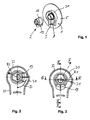
- the ventilation system is formed on the one hand by a shape of a housing opening 1 of the housing 5 and on the other hand by forming a lockable to the housing opening 1 ventilation body 2.
- housing opening 1 the region of the housing wall 5 is referred to, in which an opening is provided.
- the ventilation body 2 is integrally formed as an injection-molded part, which preferably consists of the same rigid material as the housing or the housing opening 1 integrally formed on the housing.
- the housing opening 1 has a high opening wall 3, which is cylindrical and has a circular free edge 4, which is arranged at a relatively large distance from the housing wall 5.
- the high opening wall 3 has on a bottom edge 6, which is arranged cranked in the housing wall 5, annular locking elements 7, by means of which the ventilation body 2 can be positively and / or non-positively fixed to the housing opening 1.
- the locking elements 7 extend coaxially to an axis A of the high opening wall 3 and the housing opening 1.
- the locking elements 7 extend in a bottom plane B of the housing opening 1, which is perpendicular to the axis A thereof.
- the low opening wall 8 preferably has a recess 10 in a vertically lower area, the edge 9 'of which has a smaller axial distance from the housing wall 5 than the remaining edge 9 of the low opening wall 8.
- the low opening wall 8 is coaxial with the high opening wall 3 arranged.
- the recess 10 extends in an acute angle range about the axis A, preferably in an angular range of 20 ° to 30 °.
- the ventilation body 2 consists of an engaging in the high opening wall 3 inner part 11 and outside the high opening wall
- the outer part 12 surrounds the high opening wall 3 and the low opening wall eighth
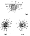
- the ventilation body 2 forms with the housing opening 1 a rotary closure, wherein the ventilation body 2 according to axial attachment to the housing opening 1 according to FIG. 2 from a brinarretierlage by rotation in the direction of rotation D (clockwise) about the axis A in an in FIG. 3 shown locking position can be brought, in which the ventilation body 2 is fixed to the housing opening 1.
- the angle of rotation by which the ventilation body 2 is rotated relative to the housing opening 1 from the non-locking position into the locking position and vice versa is 90 ° in the present exemplary embodiment.
- the angle of rotation may also be smaller or larger provided that the inner part 11 of the ventilation body 2 and the housing opening 1 are contoured accordingly.
- the inner part 11 has a foot portion 13 which is integrally connected to the outer part 12.
- the foot section 13 is adjoined by a flattened extension section 14, which is provided at a free end with locking elements 15, 15 'for the detachable fastening of the ventilation body 2 to the housing opening 1.
- the outer part 12 has a circumferentially closed wall 16, which extends at a radial distance to the foot portion 13 and extension portion 14 of the inner part 11.
- the outer part 12 is formed kelchförmig, at the inner bottom of the inner part 11 protrudes like a web, wherein the free end of the locking elements 15, 15 'extends beyond a plane formed by a free edge 17 of the outer part 12 extension plane.
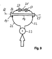
- the locking elements 15, 15 of the inner part 11 are arranged on opposite sides of the extension portion 14 and point to the coding the ventilation body 2 a different width, so that the ventilation body 2 only in a single rotational position, s. FIG. 7 , with the locking elements 15, 15 'can pass through the ground plane B of the high opening wall 3.
- the high opening wall 3 has at the bottom edge 6 corresponding notches 18, 18 'of different width to correspond to the width of the locking elements 15 and 15', so that in the non-locking position only this type of ventilation bodies on or can pass.
- the contouring of the incisions 18, 18 'and the locking elements 15, 15' thus enable a coding of the ventilation system, which ensures that only the predetermined ventilation body 2 can be locked with an open ventilation duct.
- a ventilation body of a different type, for example with an integrated membrane, would, for example, have complementary locking elements which are prevented by providing a predetermined mounting frame 30 due to further measures, namely the specification of a defined insertion position in the non-locking position.
- the locking elements 7 of the high opening wall 3 are formed by a bottom arcuate portion 7 'extending along an acute angle about the axis A and by a blocking portion 7 "located at one end of the arcuate portion 7.
- the arcuate portion 7' faces the same radius as the locking elements 15, 15 ', so that upon rotation of the ventilation body 2 relative to the housing opening 1, the locking elements 15, 15' engage behind the respective arc sections 7 'and thus produce an axial holding force between the housing opening 1 and the ventilation body 2. Further rotation of the ventilation body 2 is prevented by striking the locking elements 12 to the blocking portion 7 ".
- the blocking section 7 has, relative to the ground plane B, a greater grandeur or axial spacing than the arc sections 7 ', so that the axial surface of the blocking section 7" serves as a stop for the locking elements 15, 15' on the opposite sides.
- the outer part 12 of the ventilation body 2 has a radial projection 19 whose wall in the mounting position of the ventilation body 2 in such a large radial distance to the low opening wall 8, that an opening 20 is formed to form one end of the ventilation channel.
- the other areas of the wall 16 of the outer part 12 are on the outside of the low opening wall 8 and thus allow a seal between the ventilation body 2 and the housing opening 1.
- the breakthrough 20 is formed due to the radial distance between an edge of the projection 19 and the low opening wall 8.
- the ventilation body 2 assumes a defined axial position, the outer part 12 distributed circumferentially arranged stop elements 21 which come to a free edge of the low opening wall 8 to rest.
- the foot section 13 of the inner part 11 is arranged on a half side facing the projection 19, two arcuate ventilation channel sections 22 are formed, which extend between a first deflection 23 in the region of the opening 20 and a median plane M of the extension section 14.
- the inner part 11 On a side facing away from the projection 19, the inner part 11 has a release 24 or a deflection web 25, so that an axial ventilation channel section 26 can connect to the two arcuate ventilation channel sections 22, see arrow in FIG FIG. 5 , which represents the course of the ventilation duct.
- a second deflection 27 of the ventilation duct takes place.
- the axial ventilation channel section 26 extends between the second deflection 27 and the ground plane B of the high opening wall 3, wherein the extension section 14 and on a to the projection 19 side facing away portions of the high opening wall 3 limit this axial ventilation duct section 26. In the locking position can thus form a continuous ventilation duct between a lower edge in the vertical direction of the outer part 12 of the ventilation body 2 and an upper opening half of the high opening wall 3 in the vertical direction.
- the foot portion 13 which has a semicircular radial surface 28, sealingly against an inner side 29 of the high opening wall 3 at.
- a sealing of the ventilation body 2 to the housing opening 1 in the locking position thus takes place in a vertically lower area by sealing contact of the inner part 11 on the high opening wall 3 on the one hand and in a vertical upper area by conditioning the edge 17 of the outer part 12 at the low opening wall eighth
- the sealing contact of the edge 17 of the outer part 12 preferably encloses an obtuse angle, in particular an angle between 270 ° and 330 ° about the axis A.
- the sealing contact of the foot portion 13 of the inner part 11 at the opening wall 3 preferably encloses a blunt or obtuse angle or 180 ° about the axis A. In this way, a comprehensive seal is guaranteed.
- the wall 16 of the outer part 12 is flexible, so that a tolerance compensation to the housing wall 5 can take place. A seal can thus be saved.
- the wall 16 of the outer part 12 forms a flexible sealing surface, which rests sealingly on an outer side of the low opening wall 8, so that the wall 16 is non-positively connected in the radial direction with the low opening wall 8.
- the mounting frame 30 is provided with a bulge 31.
- the bulge 31 has a radius R1, which is greater than a radius of the radial projection 19.
- An adjoining the bulge 31 arcuate portion 32 of the mounting frame 30 has a radius R2, which is smaller than the radius of the projection 19.
- the ventilation body 2 can be placed axially in the Seaarretierlage under orientation of the radial projection 19 to the bulge 31.
- the radial projection 19 is oriented vertically in the downward direction, so that the one end of the ventilation channel is directed in the vertical direction downwards.
- the ventilation body 2 may be formed of a same or different material to the housing.
Landscapes
- Engineering & Computer Science (AREA)
- General Engineering & Computer Science (AREA)
- Non-Portable Lighting Devices Or Systems Thereof (AREA)
- Arrangement Of Elements, Cooling, Sealing, Or The Like Of Lighting Devices (AREA)
- Air-Conditioning For Vehicles (AREA)
- Securing Globes, Refractors, Reflectors Or The Like (AREA)
- Jet Pumps And Other Pumps (AREA)
- Cooling Or The Like Of Electrical Apparatus (AREA)
Abstract
Description
- Die Erfindung betrifft ein Belüftungssystem für Fahrzeugbeleuchtungen enthaltend
- eine Gehäuseöffnung mit einer vorstehenden Öffnungswandung,
- einen Belüftungskörper, der an der Gehäuseöffnung durch Eingreifen eines Innenteils desselben fixiert ist, wobei der Belüftungskörper und die Gehäuseöffnung Wandungen aufweisen zur Bildung eines Belüftungskanals mit mehreren Umlenkungen zwischen einem Rand des Belüftungskörpers und einem Durchbruch der Gehäuseöffnung.
- Aus der
EP 1 205 706 A2 ist ein Belüftungssystem für Fahrzeugleuchten bekannt, bei dem das Belüftungssystem an einer Rückseite eines Gehäuses vorgesehen ist. An der Gehäuseöffnung des Gehäuses sind mehrere nach außen abragende Wandungen unterschiedlicher Höhe vorgesehen, auf die ein kappenförmiger Belüftungskörper aufsetzbar ist. Es wird ein labyrinthartiger Belüftungskanal gebildet. Der kappenförmige Belüftungskörper ist rastend mit Wandungen der Gehäuseöffnung verbunden, wobei der kappenförmige Belüftungskörper zur Erlangung der Fixierstellung in Axialrichtung auf die Wandungen der Gehäuseöffnung aufgesetzt wird. - Aus der
EP 0 764 811 B1 ist ein Belüftungssystem für Fahrzeugbeleuchtungen mit einem Gehäuse bekannt, bei dem ein kappenförmiger Belüftungskörper in Axialrichtung auf eine Gehäuseöffnung aufgesetzt und rastend mit dieser fixiert wird. Der Belüftungskörper und die Gehäuseöffnung weisen Wände auf, sodass sich ein Belüftungskanal mit mehrere Umlenkungen zwischen einem Rand des Belüftungskörpers und einen Durchbruch der Gehäuseöffnung ausbildet. Die Fixierung des Belüftungskörpers erfolgt mittels eines Rastelementes, das in den Durchbruch der Gehäuseöffnung eingreift. Die Fixierung erfolgt durch axiales Einschnappen des Rastelementes in den Durchbruch der Gehäuseöffnung, wobei widerhakenförmige Enden des Rastelementes eine Wandung des Gehäuses hintergreifen. - Aufgabe der vorliegenden Erfindung ist es, ein Belüftungssystem derart weiterzubilden, dass eine einfache Montage und eine sichere Fixierung ermöglicht wird, die einen hohen Abdichtungsgrad und einen variablen Einsatz gewährleistet.
- Zur Lösung der Aufgabe ist die Erfindung in Verbindung mit dem Oberbegriff des Patentanspruchs 1 dadurch gekennzeichnet, dass
- das Innenteil und ein die Öffnungswandung der Gehäuseöffnung umgebendes Außenteil Wandungen aufweisen, die jeweils bereichsweise in Umfangsrichtung abdichtend an der Öffnungswandung der Gehäuseöffnung anliegen,
- der Belüftungskörper und die Gehäuseöffnung derart ausgebildet sind, dass der Belüftungskörper durch Drehung entsprechend eines vorgegebenen Drehwinkels relativ zu der Gehäuseöffnung von einer Nichtarretierlage in eine Arretierlage oder vice versa bringbar ist.
- Nach der Erfindung weist ein Belüftungskörper zum einen ein in die Gehäuseöffnung hineinragendes Innenteil und zum anderen eine Öffnungswandung der Gehäuseöffnung umgebendes Außenteil auf, die mit ihren Wandungen eine die Gehäuseöffnung abdichtende Funktion übernehmen. Der Belüftungskörper ist als ein Drehverschluss ausgebildet, sodass die Fixierung durch Drehung des Belüftungskörpers relativ zu der Gehäuseöffnung um eine Achse derselben erfolgt. Hierdurch wird eine langzeitstabile Fixierung und eine Kodierung des Belüftungssystems ermöglicht, die ein montagesicheres Fixieren von unterschiedlichen Belüftungskörpern an der gleichen Gehäuseöffnung gewährleisten.
- Nach einer bevorzugten Ausführungsform der Erfindung ist die Öffnungswandung der Gehäuseöffnung zweistufig ausgebildet. Zum einen wird ein Durchbruch der Gehäuseöffnung durch eine hohe Öffnungswandung begrenzt, deren freier Rand einen relativ großen Abstand zu einer senkrecht zur Achse der Gehäuseöffnung verlaufenden Gehäusewandung bildet. Zum anderen ist in einem radialen Abstand zu der hohen Öffnungswandung eine niedrige Öffnungswandung vorgesehen, deren freier Rand einen relativ geringen Abstand zu der Gehäusewandung aufweist. Die hohe Öffnungswandung dient im Wesentlichen zur Anlage des Innenteils an einer Innenseite derselben. An einer Rückseite weist die hohe Öffnungswandung Arretierelemente zur Festlegung des Innenteils in die Arretierlage an der Gehäuseöffnung auf. Die niedrige Öffnungswandung dient zum Abdichten der Anlage des Außenteils. Dadurch, dass die niedrige Öffnungswandung bereichsweise eine Aussparung aufweist, kann dort ein Durchgang für ein Ende des Belüftungskanals gebildet werden, wobei eine erste Umlenkung des Belüftungskanals erfolgt. Die niedrige Öffnungswandung sowie das Außenteil ermöglichen einen bogenförmigen Verlauf des Belüftungskanals, wobei sich der Belüftungskanal an der Aussparung der Öffnungswandung in zwei bogenförmige Belüftungskanalabschnitte aufteilt. Das Innenteil bzw. die hohe Öffnungswandung wird dabei in Umfangsrichtung umströmt, bis auf einer zu der Aussparung gegenüberliegenden Seite des Innenteils ein axialer Belüftungskanalabschnitt erreicht wird, der sich zwischen der hohen Öffnungswandung und dem Innenteil erstreckt. Dort ist eine zweite Umlenkung des Belüftungskanals vorgesehen. Vorteilhaft wird hierdurch ein labyrinthartiger Belüftungskanal gebildet, wobei gleichzeitig der Belüftungskörper abdichtend an der Gehäuseöffnung fixiert ist.
- Nach einer Weiterbildung der Erfindung weist das Innenteil des Belüftungskörpers sowie die hohe Öffnungswandung an einer Rückseite Arretierelemente auf, die eine form- und/oder kraftschlüssige Arretierung des Belüftungskörpers an der Gehäusewandung durch Drehung des Belüftungskörpers um eine Achse der Gehäuseöffnung ermöglicht. Vorteilhaft wird hierdurch eine sichere bajonettartige Fixierung gewährleistet, wobei der Belüftungskörper in der Arretierlage zur der Gehäuseöffnung eine definierte Montageposition einnimmt.
- Nach einer Weiterbildung der Erfindung ist das Arretierelement des Innenteils des Belüftungskörpers radial abstehend ausgebildet, sodass es in der Arretierlage einen Bogenabschnitt des an der Rückseite der hohen Öffnungswandung angeordneten Arretierelementes rastend hintergreift. Hierdurch kann eine axiale Haltekraft ausgeübt werden, die den Belüftungskörper dichtend und lagesicher in der Arretierlage hält.
- Nach einer Weiterbildung der Erfindung ist ein bodenseitiger Rand der hohen Öffnungswandung derart konturiert ausgebildet, dass lediglich ein Typ von Belüftungskörpern aus einer Mehrzahl von unterschiedlichen Typen von Belüftungskörpern in die Arretierlage bringbar ist. Hierdurch wird eine "harte Kodierung" geschaffen, die eine Kompatibilität der Gehäuseöffnung auch bspw. zu mit jeweils einer Membran versehenen Belüftungskörpern ermöglicht.
- Nach einer Weiterbildung der Erfindung weist der Belüftungskörper eine zu der Aussparung der niedrigen Öffnungswandung korrespondierende radiale Auskragung an dem Außenteil des Belüftungskörpers auf. Hierdurch wird an einer Seite des Belüftungskörpers ein Ende des Belüftungskanals definiert, wobei dieses Ende vorzugsweise in einem vertikal unteren Bereich des Belüftungssystems angeordnet ist. Vorteilhaft kann auf diese Weise der unerwünschte Eintritt von Flüssigkeiten in das Gehäuse vermieden werden.
- Nach einer Weiterbildung der Erfindung weist das Innenteil einen Fußabschnitt auf, der lediglich auf einer der radialen Auskragung zugewandten Halbseite angeordnet ist. Eine Radialfläche des Fußabschnittes dient als Anlagefläche an einer Innenseite der hohen Öffnungswandung. Auf einer der radialen Auskragung abgewandten Seite weist das Innenteil eine Aussparung bzw. einen Umlenksteg auf, sodass ein Axialabschnitt des Belüftungskanals ausgebildet wird, der sich von dem freien Rand der Öffnungswandung bis hin zu einer Bodenebene der Öffnungswandung erstreckt. Dadurch, dass das Innenteil in einem sich an dem Fußabschnitt anschließenden Verlängerungsabschnitts abgeflacht ausgebildet ist, kann sich der Axialabschnitt des Belüftungskanals in der Arretierlage des Belüftungskörpers ausbilden.
- Nach einer Weiterbildung der Erfindung weist die Gehäuseöffnung einen in einem radialen Abstand zu der hohen Öffnungswandung und zu der niedrigen Öffnungswandung angeordneten Montierrahmen auf, dessen Radius nur in einem Drehwinkelbereich des Belüftungskörpers größer ist als ein Radius der radialen Auskragung des Belüftungskörpers. Auf diese Weise wird eine definierte Einsatzlage des Belüftungskörpers in der Nichtarretierlage definiert bzw. die Drehung des Belüftungskörpers von der Nichtarretierlage in die Arretierlage und umgekehrt vorgegeben. Vorteilhaft kann hierdurch die Montage erleichtert werden. Darüber hinaus ermöglicht der Montierrahmen einen Spritzschutz des Belüftungssystems.
- Weitere Vorteile der Erfindung ergeben sich aus den weiteren Unteransprüchen.
- Ein Ausführungsbeispiel der Erfindung wird nachfolgend anhand der Zeichnungen näher erläutert.
- Es zeigt:
- Figur 1
- eine Explosionsdarstellung eines Belüftungssystems mit einer Gehäuseöffnung sowie einem Belüftungskörper,
- Figur 2
- eine Vorderansicht des Belüftungssystems in einer Nichtarretierlage des Belüftungskörpers,
- Figur 3
- eine Vorderansicht des Belüftungssystems in einer Arretierlage des Belüftungskörpers,
- Figur 4
- einen Vertikalschnitt durch das Belüftungssystem entlang der Schnittlinie IV-IV in
Figur 3 , - Figur 5
- einen Schnitt durch das Belüftungssystem entlang der Schnittlinie V-V in
Figur 3 , - Figur 6
- einen Horizontalschnitt durch das Belüftungssystem entlang der Schnittlinie VI-VI in
Figur 3 , - Figur 7
- eine Rückansicht des Belüftungssystems in einer Nichtarretierlage des Belüftungskörpers,
- Figur 8
- eine Rückansicht des Belüftungssystems in einer Arretierlage des Belüftungskörpers und
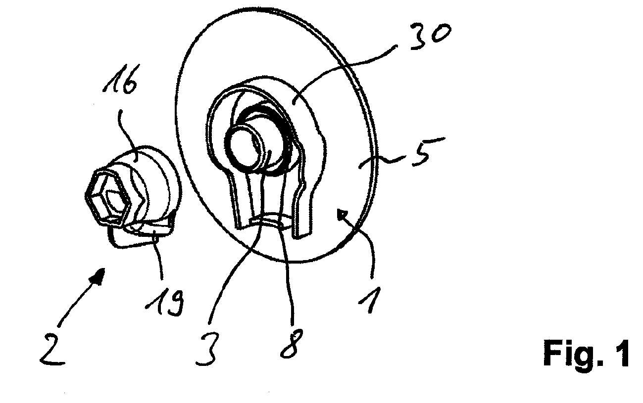
- Figur 9
- eine schematische Darstellung des Verlaufs eines durch das Belüftungssystem ausgebildeten Belüftungskanals.
- Ein erfindungsgemäßes Belüftungssystem kann für Fahrzeugbeleuchtungen, insbesondere Scheinwerfer eingesetzt werden. Alternativ kann das Belüftungssystem auch für die Belüftung und/oder Druckausgleich von anderen Gehäusen, bspw. Steuergeräten, Batterien eingesetzt werden.
- Eine Beleuchtungsvorrichtung für Fahrzeuge kann im Bug- oder Heckbereich des Fahrzeuges angeordnet sein. Die Beleuchtungsvorrichtung weist ein Gehäuse auf, in dem mindestens eine Lichtquelle und eine derselben zugeordnete Optikeinheit angeordnet sind zur Erzeugung eines Lichtbündels. Mittels des Lichtbündels kann eine vorgegebene Lichtverteilung, wie bspw. eine Abblendlichtverteilung oder eine Fernlichtverteilung erzeugt werden. Das aus einem starren Material bestehende Gehäuse weist in Hauptabstrahlrichtung vorne eine Öffnung auf, die durch eine lichtdurchlässige Abschlussscheibe abgedeckt ist. An einer Rückseite des Gehäuses, vorzugsweise an einer vertikalen Gehäusewand 5 des Gehäuses, ist ein Belüftungssystem zum wechselseitigen Austausch von Luft zwischen einem Inneren des Gehäuses und der Umgebung vorgesehen. Das Belüftungssystem ist zum einen durch eine Ausformung einer Gehäuseöffnung 1 der Gehäusewandung 5 und zum anderen durch Ausbildung eines an die Gehäuseöffnung 1 arretierbaren Belüftungskörpers 2 gebildet. Unter Gehäuseöffnung 1 wird der Bereich der Gehäusewand 5 bezeichnet, in der ein Durchbruch vorgesehen ist.
- Der Belüftungskörper 2 ist einstückig als ein Spritzgießteil ausgebildet, das vorzugsweise aus dem gleichen starren Material besteht wie das Gehäuse bzw. die an das Gehäuse angeformte Gehäuseöffnung 1.
- Die Gehäuseöffnung 1 weist eine hohe Öffnungswandung 3 auf, die zylinderförmig ausgebildet ist und einen kreisförmigen freien Rand 4 aufweist, der in einem relativ großen Abstand zu der Gehäusewand 5 angeordnet ist. Die hohe Öffnungswandung 3 weist an einem bodenseitigen Rand 6, der in der Gehäusewand 5 gekröpft angeordnet ist, ringförmige Arretierelemente 7 auf, mittels dessen der Belüftungskörper 2 form- und/oder kraftschlüssig an der Gehäuseöffnung 1 fixiert werden kann. Die Arretierelemente 7 erstrecken sich koaxial zu einer Achse A der hohen Öffnungswandung 3 bzw. der Gehäuseöffnung 1. Die Arretierelemente 7 erstrecken sich in einer Bodenebene B der Gehäuseöffnung 1, die senkrecht zu der Achse A derselben verläuft.
- In einem radialen Abstand zu der hohen Öffnungswandung 3 ist dieselbe durch eine niedrige Öffnungswandung 8 umgeben, die einen freien Rand 9 aufweist, der im Vergleich zu dem Rand 4 der hohen Öffnungswandung 3 einen kleineren Abstand zu der im Wesentlichen senkrecht zu der Achse A verlaufenden Gehäusewand 5 aufweist. Die niedrige Öffnungswandung 8 weist vorzugsweise in einem vertikal unteren Bereich eine Aussparung 10 auf, deren Rand 9' einen geringeren axialen Abstand zu der Gehäusewand 5 aufweist als der restliche Rand 9 der niedrigen Öffnungswandung 8. Die niedrige Öffnungswandung 8 ist koaxial zu der hohen Öffnungswandung 3 angeordnet. Die Aussparung 10 erstreckt sich in einem spitzen Winkelbereich um die Achse A, vorzugsweise in einem Winkelbereich von 20° bis 30°.
- Der Belüftungskörper 2 besteht aus einem in die hohe Öffnungswandung 3 eingreifenden Innenteil 11 und einem außerhalb der hohen Öffnungswandung 3 verlaufenden Außenteil 12. Das Außenteil 12 umgibt die hohe Öffnungswandung 3 bzw. die niedrige Öffnungswandung 8.
- Der Belüftungskörper 2 bildet mit der Gehäuseöffnung 1 einen Drehverschluss, wobei der Belüftungskörper 2 nach axialem Ansetzen an die Gehäuseöffnung 1 gemäß
Figur 2 von einer Nichtarretierlage durch Drehung in Drehrichtung D (im Uhrzeigersinn) um die Achse A in eine inFigur 3 dargestellte Arretierlage bringbar ist, in der der Belüftungskörper 2 an der Gehäuseöffnung 1 fixiert ist. Der Drehwinkel, um den der Belüftungskörper 2 relativ zu der Gehäuseöffnung 1 von der Nichtarretierlage in die Arretierlage und umgekehrt verdreht wird, beträgt im vorliegenden Ausführungsbeispiel 90°. Alternativ kann der Drehwinkel auch kleiner oder größer vorgesehen sein, wenn das Innenteil 11 des Belüftungskörpers 2 und die Gehäuseöffnung 1 entsprechend konturiert sind. - Das Innenteil 11 weist einen Fußabschnitt 13 auf, der mit dem Außenteil 12 einstückig verbunden ist. An den Fußabschnitt 13 schließt sich ein abgeflachter Verlängerungsabschnitt 14 an, der an einem freien Ende mit Arretierelementen 15, 15' versehen ist zur lösbaren Befestigung des Belüftungskörpers 2 an der Gehäuseöffnung 1.
- Das Außenteil 12 weist eine in Umfangsrichtung geschlossene Wandung 16 auf, die in einem radialen Abstand zu dem Fußabschnitt 13 bzw. Verlängerungsabschnitt 14 des Innenteils 11 verläuft. Das Außenteil 12 ist kelchförmig ausgebildet, an dessen inneren Boden das Innenteil 11 stegartig abragt, wobei dessen freies Ende mit den Arretierelementen 15, 15' über eine durch einen freien Rand 17 des Außenteils 12 gebildete Erstreckungsebene hinausreicht.
- Die Arretierelemente 15, 15 des Innenteils 11 sind an gegenüberliegenden Seiten des Verlängerungsabschnittes 14 angeordnet und weisen zur Kodierung des Belüftungskörpers 2 eine unterschiedliche Breite auf, sodass der Belüftungskörper 2 nur in einer einzigen Drehstellung, s.
Figur 7 , mit den Arretierelementen 15, 15' durch die Bodenebene B der hohen Öffnungswandung 3 durchgreifen kann. Die hohe Öffnungswandung 3 weist an dem bodenseitigen Rand 6 entsprechende Einschnitte 18, 18' unterschiedlicher Breite auf die zu der Breite der Arretierelemente 15 bzw. 15' korrespondieren, sodass in der Nichtarretierlage nur dieser Typ von Belüftungskörpern ein- bzw. durchgreifen kann. Die Konturierung der Einschnitte 18, 18' bzw. der Arretierelemente 15, 15' ermöglichen somit eine Kodierung des Belüftungssystems, das sicherstellt, dass nur der vorgegebene Belüftungskörper 2 mit einem offenen Belüftungskanal arretiert werden kann. Ein Belüftungskörper eines anderen Typs, bspw. mit einer integrierten Membran, würde bspw. komplementär ausgebildete Arretierelemente aufweisen, die aufgrund weiteren Maßnahmen, nämlich der Vorgabe einer definierten Einsteckposition in die Nichtarretierlage durch Versehen eines vorgegebenen Montierrahmens 30 verhindert wird. - Die Arretierelemente 7 der hohen Öffnungswandung 3 sind gebildet durch einen bodenseitigen Bogenabschnitt 7', der sich entlang eines spitzen Winkels um die Achse A erstreckt und durch einen Blockierabschnitt 7", der an einem Ende des Bogenabschnittes 7' angeordnet ist. Der Bogenabschnitt 7' weist den gleichen Radius auf wie die Arretierelemente 15, 15', sodass beim Verdrehen des Belüftungskörpers 2 relativ zu der Gehäuseöffnung 1 die Arretierelemente 15, 15' die jeweiligen Bogenabschnitte 7' hintergreifen und damit eine axiale Haltekraft zwischen der Gehäuseöffnung 1 und dem Belüftungskörper 2 erzeugen. Ein Weiterdrehen des Belüftungskörpers 2 wird durch Anschlagen der Arretierelemente 12 an den Blockierabschnitt 7" verhindert. Der Blockierabschnitt 7" weist bezogen auf die Bodenebene B eine größere Erhabenheit bzw. axialen Abstand auf als die Bogenabschnitte 7', sodass die axiale Fläche des Blockierabschnittes 7" als Anschlag für die Arretierelemente 15, 15' an den gegenüberliegenden Seiten dient.
- Das Außenteil 12 des Belüftungskörpers 2 weist eine radiale Auskragung 19 auf, deren Wandung in der Montageposition des Belüftungskörpers 2 in einem solchen großen radialen Abstand zu der niedrigen Öffnungswandung 8 aufweist, dass ein Durchbruch 20 zur Bildung eines Endes des Belüftungskanals gebildet ist. Die anderen Bereiche der Wandung 16 des Außenteils 12 liegen außenseitig an der niedrigen Öffnungswandung 8 an und ermöglichen somit eine Abdichtung zwischen dem Belüftungskörper 2 und der Gehäuseöffnung 1. Wie aus den
Figuren 4 und 5 zu ersehen ist, wird aufgrund des radialen Abstandes zwischen einem Rand der Auskragung 19 und der niedrigen Öffnungswandung 8 der Durchbruch 20 gebildet. - Damit der Belüftungskörper 2 eine definierte Axiallage einnimmt, weist das Außenteil 12 in Umfangsrichtung verteilt angeordnete Anschlagelemente 21 auf, die auf einen freien Rand der niedrigen Öffnungswandung 8 zu Anlage kommen.
- Da der Fußabschnitt 13 des Innenteils 11 auf einer der Auskragung 19 zugewandten Halbseite angeordnet ist, bilden sich zwei bogenförmige Belüftungskanalabschnitte 22 aus, die sich zwischen einer ersten Umlenkung 23 im Bereich des Durchbruches 20 und einer Mittelebene M des Verlängerungsabschnittes 14 erstrecken. Auf einer der Auskragung 19 abgewandten Seiten weist das Innenteil 11 eine Freilassung 24 bzw. einen Umlenksteg 25 auf, sodass sich an die beiden bogenförmigen Belüftungskanalabschnitte 22 ein axialer Belüftungskanalabschnitt 26 anschließen kann, siehe Pfeil in
Figur 5 , der den Verlauf des Belüftungskanals darstellt. Im Bereich des Übergangs zwischen der Freilassung 24 und dem Fußabschnitt 13 erfolgt eine zweite Umlenkung 27 des Belüftungskanals. Der axiale Belüftungskanalabschnitt 26 erstreckt sich zwischen der zweiten Umlenkung 27 und der Bodenebene B der hohen Öffnungswandung 3, wobei der Verlängerungsabschnitt 14 und auf einer zur Auskragung 19 abgewandten Seite angeordnete Abschnitte der hohen Öffnungswandung 3 diesen axialen Belüftungskanalabschnitt 26 begrenzen. In der Arretierlage kann sich somit ein durchgehender Belüftungskanal zwischen einem in vertikaler Richtung unteren Rand des Außenteils 12 des Belüftungskörpers 2 und einer in vertikaler Richtung oberen Öffnungshälfte der hohen Öffnungswandung 3 ausbilden. - In der Arretierlage liegt der Fußabschnitt 13, der eine halbkreisförmige Radialfläche 28 aufweist, abdichtend an einer Innenseite 29 der hohen Öffnungswandung 3 an.
- Eine Abdichtung des Belüftungskörpers 2 zu der Gehäuseöffnung 1 in der Arretierlage erfolgt somit in einem vertikal unteren Bereich durch dichtende Anlage des Innenteils 11 an der hohen Öffnungswandung 3 einerseits und in einem vertikal oberen Bereich durch Anlage des Randes 17 des Außenteils 12 an der niedrigen Öffnungswandung 8. Die dichtende Anlage des Randes 17 des Außenteils 12 umschließt vorzugsweise einen überstumpfen Winkel, insbesondere einen Winkel zwischen 270° und 330° um die Achse A. Die dichtende Anlage des Fußabschnittes 13 des Innenteils 11 an der Öffnungswandung 3 umschließt vorzugsweise einen stumpfen oder überstumpfen Winkel oder 180° um die Achse A. Auf diese Weise ist eine umfassende Abdichtung gewährleistet. Vorzugsweise ist die Wandung 16 des Außenteils 12 flexibel ausgebildet, sodass ein Toleranzausgleich zu der Gehäusewand 5 erfolgen kann. Eine Dichtung kann somit eingespart werden. Die Wandung 16 des Außenteils 12 bildet eine flexible Dichtfläche, die dichtend auf einer äußeren Seite der niedrigen Öffnungswandung 8 anliegt, so dass die Wandung 16 kraftschlüssig in radialer Richtung mit der niedrigen Öffnungswandung 8 verbunden ist. Hierdurch wird zum einen eine Dichtfunktion und zum anderen eine Befestigungsfunktion erreicht, wobei durch die Befestigungsfunktion verhindert wird, dass sich der Belüftungskörper 2 von dem Gehäuse bei Vibrationen im Betrieb des Belüftungssystems lösen kann.
- Zum kodierten Ansetzen des Belüftungskörpers 2 an der Gehäuseöffnung 1 ist der Montierrahmen 30 mit einer Ausbuchtung 31 vorgesehen. Die Ausbuchtung 31 weist einen Radius R1 auf, der größer ist als ein Radius der radialen Auskragung 19. Ein sich an die Ausbuchtung 31 anschließender bogenförmiger Abschnitt 32 des Montierrahmens 30 weist einen Radius R2 auf, der kleiner ist als der Radius der Auskragung 19. Da der Montierrahmen 30 sich lediglich in einem überstumpfen Winkel erstreckt und in vertikaler Richtung nach unten offen ausgebildet ist, kann der Belüftungskörper 2 in der Nichtarretierlage unter Orientierung der radialen Auskragung 19 zu der Ausbuchtung 31 axial aufgesetzt werden. Durch relative Drehung des Belüftungskörpers 2 in Drehrichtung D kann dieser dann in die Arretierlage verbracht werden, in der die Arretierelemente 15, 15' den bodenseitigen Rand 6 der hohen Öffnungswandung 3 hintergreifen. In der Arretierlage ist die radiale Auskragung 19 vertikal in Richtung nach unten orientiert, sodass das eine Ende des Belüftungskanals in vertikaler Richtung nach unten gerichtet ist.
- Das Verbringen des Belüftungskörpers 2 aus der Arretierlage in die Nichtarretierlage erfolgt in umgekehrter Drehrichtung.
- Der Belüftungskörper 2 kann aus einem gleichen oder anderen Material zu dem Gehäuse ausgebildet sein.
Claims (10)
- Belüftungssystem für Fahrzeugbeleuchtungen enthaltend- eine Gehäuseöffnung (1) mit einer vorstehenden Öffnungswandung (3, 8),- einen Belüftungskörper (2), der an der Gehäuseöffnung (1) durch Eingreifen eines Innenteils desselben fixiert ist, wobei der Belüftungskörper (2) und die Gehäuseöffnung (1) Wandungen (17, 25, 28) aufweisen zur Bildung eines Belüftungskanals mit mehreren Umlenkungen zwischen einem Rand des Belüftungskörpers (2) und einem Durchbruch der Gehäuseöffnung (1),
dadurch gekennzeichnet, dass- das Innenteil (11) und ein die Öffnungswandung (3, 8) der Gehäuseöffnung (1) umgebendes Außenteil (12) Wandungen (17, 25, 28) aufweisen, die jeweils bereichsweise in Umfangsrichtung abdichtend an der Öffnungswandung (3, 8) der Gehäuseöffnung (1) anliegen,- der Belüftungskörper (2) und die Gehäuseöffnung (1) derart ausgebildet sind, dass der Belüftungskörper (2) durch Drehung entsprechend eines vorgegebenen Drehwinkels relativ zu der Gehäuseöffnung (1) von einer Nichtarretierlage in eine Arretierlage oder vice versa bringbar ist. - Belüftungssystem nach Anspruch 1, dadurch gekennzeichnet, dass die Öffnungswandung der Gehäuseöffnung (1) durch eine den Durchbruch begrenzende hohe Öffnungswandung (3) und eine in radialem Abstand zu derselben angeordnete niedrige Öffnungswandung (8) gebildet ist, wobei die hohe Öffnungswandung (3) an einer Rückseite Arretierelemente (7, 7', 7") zur Festlegung des Innenteils (11) des Belüftungskörpers (2) in der Arretierlage und wobei die niedrige Öffnungswandung (8) eine Aussparung (10) aufweist zur Bildung eines Durchbruchs (20) an einem Ende des Belüftungskanals.
- Belüftungssystem nach Anspruch 1 oder 2, dadurch gekennzeichnet, dass die Arretierelemente (7, 7', 7") der hohen Öffnungswandung (3) und/oder des Innenteils (11) derart ausgebildet sind, dass der Belüftungskörper (2) in der Arretierlage form- und/oder kraftschlüssig an der Gehäuseöffnung (1) gehalten ist.
- Belüftungssystem nach einem der Ansprüche 1 bis 3, dadurch gekennzeichnet, dass das Innenteil (11) des Belüftungskörpers (2) an dem freien Ende ein radial abstehendes Arretierelement (15, 15') aufweist, das einen bodenseitigen Bogenabschnitt (7') des Arretierelememtes (7) der hohen Gehäuseöffnung (1) in der Arretierlage rastend hintergreift.
- Belüftungssystem nach einem der Ansprüche 1 bis 4, dadurch gekennzeichnet, dass ein bodenseitiger Rand (6) der hohen Öffnungswandung (3) derart konturiert ist, dass lediglich ein Typ von Belüftungskörpern (2) aus einer Mehrzahl von unterschiedlichen Typen von Belüftungskörpern in die Arretierlage bringbar ist.
- Belüftungssystem nach einem der Ansprüche 1 bis 5, dadurch gekennzeichnet, dass der Belüftungskörper (2) an dem Außenteil (12) eine radiale Auskragung (19) aufweist, die in der Arretierlage auf einer der Aussparung (10) der niedrigen Öffnungswandung (8) zugewandten Seiten angeordnet ist.
- Belüftungssystem nach einem der Ansprüche 1 bis 6, dadurch gekennzeichnet, dass der Belüftungskörper (2) derart ausgebildet ist, dass sich auf einer dem äußeren Ende des Belüftungskanals zugewandten Halbseite zwischen dem Außenteil (12) und der höheren Öffnungswandung (3) zwei bogenförmige Belüftungskanalabschnitte (22) ausbilden, die auf einer der radialen Abkragung (19) abgewandten Seite des Innenteils (11) wieder zusammenlaufen.
- Belüftungssystem nach einem der Ansprüche 1 bis 7, dadurch gekennzeichnet, dass das Innenteil (11) einen Fußabschnitt (13) auf einer der radialen Auskragung (19) zugewandten Seite aufweist, die eine Radialfläche (28) aufweist, die an einer Innenseite (29) der hohen Öffnungswandung (3) dichtend anliegt.
- Belüftungssystem nach einem der Ansprüche 1 bis 8, dadurch gekennzeichnet, dass das Innenteil (11) auf einer der radialen Auskragung (19) abgewandten Seiten eine Freilassung (24) und/oder einen Umlenksteg (25) aufweist zur Bildung eines axialen Belüftungskanalabschnittes (26), der sich bis zu der Bodenebene (B) der Gehäuseöffnung (1) erstreckt.
- Belüftungssystem nach einem der Ansprüche 1 bis 9, dadurch gekennzeichnet, dass die Gehäuseöffnung (1) einen hervorstehenden Montierrahmen (30) mit einem bogenförmigen Abschnitt (32) und mit einer Ausbuchtung (31) aufweist, wobei die Ausbuchtung derart ausgebildet ist, dass der Belüftungskörper (2) nur in einem begrenzten Drehwinkelbereich zwischen der Nichtarretierlage und der Arretierlage unter durchsteckender Position von dem Arretierelement (15, 15`) des Innenteils (11) in dem Durchbruch der hohen Öffnungswandung (13) verdrehbar ist.
Applications Claiming Priority (1)
| Application Number | Priority Date | Filing Date | Title |
|---|---|---|---|
| DE102014106502.6A DE102014106502A1 (de) | 2014-05-08 | 2014-05-08 | Belüftungssystem für Fahrzeugbeleuchtungen |
Publications (3)
| Publication Number | Publication Date |
|---|---|
| EP2942562A2 true EP2942562A2 (de) | 2015-11-11 |
| EP2942562A3 EP2942562A3 (de) | 2015-12-02 |
| EP2942562B1 EP2942562B1 (de) | 2017-06-07 |
Family
ID=53039311
Family Applications (1)
| Application Number | Title | Priority Date | Filing Date |
|---|---|---|---|
| EP15165860.6A Active EP2942562B1 (de) | 2014-05-08 | 2015-04-30 | Belüftungssystem für fahrzeugbeleuchtungen |
Country Status (5)
| Country | Link |
|---|---|
| US (1) | US9618176B2 (de) |
| EP (1) | EP2942562B1 (de) |
| JP (1) | JP6543081B2 (de) |
| CN (1) | CN105090856B (de) |
| DE (1) | DE102014106502A1 (de) |
Families Citing this family (1)
| Publication number | Priority date | Publication date | Assignee | Title |
|---|---|---|---|---|
| DE102020112963B3 (de) | 2020-05-13 | 2021-10-07 | HELLA GmbH & Co. KGaA | Lüftersystem für einen Scheinwerfer eines Kraftfahrzeugs, Scheinwerfer und Kraftfahrzeug |
Citations (2)
| Publication number | Priority date | Publication date | Assignee | Title |
|---|---|---|---|---|
| EP1205706A2 (de) | 2000-11-07 | 2002-05-15 | Hella KG Hueck & Co. | Belüftungssystem einer Leuchte, insbesondere eines Scheinwerfers für Fahrzeuge |
| EP0764811B1 (de) | 1995-09-19 | 2002-11-06 | Valeo Vision | Fahrzeug-Beleuchtungs- oder Signaleinrichtung mit verbesserten Ventilationsmitteln |
Family Cites Families (10)
| Publication number | Priority date | Publication date | Assignee | Title |
|---|---|---|---|---|
| FR2232465B3 (de) * | 1973-06-07 | 1976-03-12 | Bosch Gmbh Robert | |
| JPS6228010Y2 (de) * | 1980-12-20 | 1987-07-18 | ||
| IT219095Z2 (it) * | 1989-11-03 | 1992-12-01 | Carello Spa | Proiettore per veicoli, in particolare autoveicoli |
| JP3195273B2 (ja) * | 1997-06-06 | 2001-08-06 | 株式会社小糸製作所 | 車輌用灯具 |
| JP4425067B2 (ja) * | 2004-06-14 | 2010-03-03 | 日東電工株式会社 | 通気部材の製造方法 |
| JP2007059200A (ja) * | 2005-08-24 | 2007-03-08 | Sumitomo Wiring Syst Ltd | 通気部材の取付け構造 |
| US8517574B2 (en) * | 2010-04-30 | 2013-08-27 | Sunonwealth Electric Machine Industry Co., Ltd. | Lamp with air channel |
| FR2987427B1 (fr) * | 2012-01-27 | 2015-03-20 | Valeo Illuminacion | Ventilation d'un boitier de dispositif d'eclairage ou de signalisation d'un vehicule |
| ITMI20120654A1 (it) * | 2012-04-19 | 2013-10-20 | Gvs Spa | Elemento di ventilazione di un involucro contenente un organo elettrico, meccanico o elettromeccanico |
| CN203322799U (zh) * | 2013-06-08 | 2013-12-04 | 东莞勤上光电股份有限公司 | 一种led筒灯 |
-
2014
- 2014-05-08 DE DE102014106502.6A patent/DE102014106502A1/de not_active Withdrawn
-
2015
- 2015-04-30 EP EP15165860.6A patent/EP2942562B1/de active Active
- 2015-05-07 JP JP2015095046A patent/JP6543081B2/ja active Active
- 2015-05-08 CN CN201510455338.0A patent/CN105090856B/zh active Active
- 2015-05-08 US US14/707,633 patent/US9618176B2/en active Active
Patent Citations (2)
| Publication number | Priority date | Publication date | Assignee | Title |
|---|---|---|---|---|
| EP0764811B1 (de) | 1995-09-19 | 2002-11-06 | Valeo Vision | Fahrzeug-Beleuchtungs- oder Signaleinrichtung mit verbesserten Ventilationsmitteln |
| EP1205706A2 (de) | 2000-11-07 | 2002-05-15 | Hella KG Hueck & Co. | Belüftungssystem einer Leuchte, insbesondere eines Scheinwerfers für Fahrzeuge |
Also Published As
| Publication number | Publication date |
|---|---|
| JP2015216116A (ja) | 2015-12-03 |
| CN105090856A (zh) | 2015-11-25 |
| CN105090856B (zh) | 2019-06-25 |
| JP6543081B2 (ja) | 2019-07-10 |
| DE102014106502A1 (de) | 2015-11-12 |
| EP2942562A3 (de) | 2015-12-02 |
| EP2942562B1 (de) | 2017-06-07 |
| US20150323150A1 (en) | 2015-11-12 |
| US9618176B2 (en) | 2017-04-11 |
Similar Documents
| Publication | Publication Date | Title |
|---|---|---|
| EP3692269B1 (de) | Winkelkupplung | |
| WO2016177364A1 (de) | Anordnung mit einer wanddurchführung für mehrere kabel sowie verfahren zum herstellen und bausatz | |
| EP3131795A1 (de) | Wischeranlage | |
| DE202016104056U1 (de) | Drehverschluss | |
| EP4010601B1 (de) | Verriegelungselement zur lösbaren verriegelung einer drehbewegung eines adapters relativ zu einem körper einer zug-druck-stange sowie zug-druck-stange mit einem solchen verriegelungselement | |
| EP2942560B1 (de) | Belüftungssystem für fahrzeugbeleuchtungen | |
| DE102013000628B4 (de) | Halterahmen einer Frischluftklappe eines Kraftfahrzeuges sowie Frischluftklappe mit Halterahmen | |
| DE102010012018A1 (de) | Entlüftungsventil | |
| DE102014105876A1 (de) | Motorlagerung für einen Motor, insbesondere eines Ventilators eines Fahrzeugklimageräts | |
| DE102011100986B3 (de) | Bedienvorrichtung, insbesondere für eine Fahrzeugkomponente | |
| EP2942562B1 (de) | Belüftungssystem für fahrzeugbeleuchtungen | |
| DE102019132227A1 (de) | Entlüftungseinheit mit Gewindeabschnitt | |
| DE102010052589A1 (de) | Befestigung eines Geberzylinders an einer Fahrzeugwand | |
| DE102005002853B3 (de) | Wellenaxialbefestigung mittels eines Drahtbügels | |
| DE3818565A1 (de) | Schwenkbares leitelement, insbesondere fuer eine zu einem kraftfahrzeug gehoerende anlage zur klimatisierung dessen fahrgastraumes | |
| DE102018126221A1 (de) | Flüssigkeitsbehältersystem, insbesondere für Scheibenwaschflüssigkeit | |
| DE102016010641A1 (de) | Membran-Rückschlagventil für eine Druckluftanlage | |
| WO2007095911A1 (de) | Karosseriedichtung lenksäulendurchführung | |
| DE102010019926A1 (de) | Befestigungsanordnung zum lösbaren Befestigen eines Anbauteils | |
| DE4216275C1 (en) | Setting mechanism for vehicle headlamp rear reflector - has external gearwheel in opening of headlamp housing fitted with rigid plastics material cover receiving drive rod | |
| DE10122952A1 (de) | Bremskraftverstärker mit einem Anschlußelement mit definierter Winkellage | |
| DE102010024501A1 (de) | Dichtelementebefestigungssystem für einen Druckbehälter, insbesondere einen Reaktordruckbehälter | |
| DE10248740B4 (de) | Rund-Luftdüse | |
| DE102021213409A1 (de) | Ventil zur Steuerung eines Fluidstroms | |
| DE102012201821B4 (de) | Befestigungsanordnung zwischen einem Betätigungszug und einem zu betätigenden Bauelement |
Legal Events
| Date | Code | Title | Description |
|---|---|---|---|
| PUAL | Search report despatched |
Free format text: ORIGINAL CODE: 0009013 |
|
| PUAI | Public reference made under article 153(3) epc to a published international application that has entered the european phase |
Free format text: ORIGINAL CODE: 0009012 |
|
| AK | Designated contracting states |
Kind code of ref document: A2 Designated state(s): AL AT BE BG CH CY CZ DE DK EE ES FI FR GB GR HR HU IE IS IT LI LT LU LV MC MK MT NL NO PL PT RO RS SE SI SK SM TR |
|
| AX | Request for extension of the european patent |
Extension state: BA ME |
|
| AK | Designated contracting states |
Kind code of ref document: A3 Designated state(s): AL AT BE BG CH CY CZ DE DK EE ES FI FR GB GR HR HU IE IS IT LI LT LU LV MC MK MT NL NO PL PT RO RS SE SI SK SM TR |
|
| AX | Request for extension of the european patent |
Extension state: BA ME |
|
| RIC1 | Information provided on ipc code assigned before grant |
Ipc: F21S 8/10 20060101ALN20151023BHEP Ipc: F21W 101/10 20060101ALI20151023BHEP Ipc: F21V 31/03 20060101AFI20151023BHEP |
|
| 17P | Request for examination filed |
Effective date: 20160530 |
|
| RBV | Designated contracting states (corrected) |
Designated state(s): AL AT BE BG CH CY CZ DE DK EE ES FI FR GB GR HR HU IE IS IT LI LT LU LV MC MK MT NL NO PL PT RO RS SE SI SK SM TR |
|
| GRAP | Despatch of communication of intention to grant a patent |
Free format text: ORIGINAL CODE: EPIDOSNIGR1 |
|
| RIC1 | Information provided on ipc code assigned before grant |
Ipc: F21W 101/10 20060101ALI20161221BHEP Ipc: F21V 31/03 20060101AFI20161221BHEP Ipc: F21S 8/10 20060101ALN20161221BHEP |
|
| INTG | Intention to grant announced |
Effective date: 20170120 |
|
| GRAS | Grant fee paid |
Free format text: ORIGINAL CODE: EPIDOSNIGR3 |
|
| AK | Designated contracting states |
Kind code of ref document: B1 Designated state(s): AL AT BE BG CH CY CZ DE DK EE ES FI FR GB GR HR HU IE IS IT LI LT LU LV MC MK MT NL NO PL PT RO RS SE SI SK SM TR |
|
| REG | Reference to a national code |
Ref country code: GB Ref legal event code: FG4D Free format text: NOT ENGLISH |
|
| GRAA | (expected) grant |
Free format text: ORIGINAL CODE: 0009210 |
|
| REG | Reference to a national code |
Ref country code: CH Ref legal event code: EP Ref country code: AT Ref legal event code: REF Ref document number: 899520 Country of ref document: AT Kind code of ref document: T Effective date: 20170615 |
|
| REG | Reference to a national code |
Ref country code: IE Ref legal event code: FG4D Free format text: LANGUAGE OF EP DOCUMENT: GERMAN |
|
| REG | Reference to a national code |
Ref country code: DE Ref legal event code: R096 Ref document number: 502015001160 Country of ref document: DE |
|
| REG | Reference to a national code |
Ref country code: NL Ref legal event code: MP Effective date: 20170607 |
|
| REG | Reference to a national code |
Ref country code: LT Ref legal event code: MG4D |
|
| PG25 | Lapsed in a contracting state [announced via postgrant information from national office to epo] |
Ref country code: FI Free format text: LAPSE BECAUSE OF FAILURE TO SUBMIT A TRANSLATION OF THE DESCRIPTION OR TO PAY THE FEE WITHIN THE PRESCRIBED TIME-LIMIT Effective date: 20170607 Ref country code: LT Free format text: LAPSE BECAUSE OF FAILURE TO SUBMIT A TRANSLATION OF THE DESCRIPTION OR TO PAY THE FEE WITHIN THE PRESCRIBED TIME-LIMIT Effective date: 20170607 Ref country code: HR Free format text: LAPSE BECAUSE OF FAILURE TO SUBMIT A TRANSLATION OF THE DESCRIPTION OR TO PAY THE FEE WITHIN THE PRESCRIBED TIME-LIMIT Effective date: 20170607 Ref country code: GR Free format text: LAPSE BECAUSE OF FAILURE TO SUBMIT A TRANSLATION OF THE DESCRIPTION OR TO PAY THE FEE WITHIN THE PRESCRIBED TIME-LIMIT Effective date: 20170908 Ref country code: NO Free format text: LAPSE BECAUSE OF FAILURE TO SUBMIT A TRANSLATION OF THE DESCRIPTION OR TO PAY THE FEE WITHIN THE PRESCRIBED TIME-LIMIT Effective date: 20170907 Ref country code: ES Free format text: LAPSE BECAUSE OF FAILURE TO SUBMIT A TRANSLATION OF THE DESCRIPTION OR TO PAY THE FEE WITHIN THE PRESCRIBED TIME-LIMIT Effective date: 20170607 |
|
| PG25 | Lapsed in a contracting state [announced via postgrant information from national office to epo] |
Ref country code: NL Free format text: LAPSE BECAUSE OF FAILURE TO SUBMIT A TRANSLATION OF THE DESCRIPTION OR TO PAY THE FEE WITHIN THE PRESCRIBED TIME-LIMIT Effective date: 20170607 Ref country code: RS Free format text: LAPSE BECAUSE OF FAILURE TO SUBMIT A TRANSLATION OF THE DESCRIPTION OR TO PAY THE FEE WITHIN THE PRESCRIBED TIME-LIMIT Effective date: 20170607 Ref country code: SE Free format text: LAPSE BECAUSE OF FAILURE TO SUBMIT A TRANSLATION OF THE DESCRIPTION OR TO PAY THE FEE WITHIN THE PRESCRIBED TIME-LIMIT Effective date: 20170607 Ref country code: LV Free format text: LAPSE BECAUSE OF FAILURE TO SUBMIT A TRANSLATION OF THE DESCRIPTION OR TO PAY THE FEE WITHIN THE PRESCRIBED TIME-LIMIT Effective date: 20170607 Ref country code: BG Free format text: LAPSE BECAUSE OF FAILURE TO SUBMIT A TRANSLATION OF THE DESCRIPTION OR TO PAY THE FEE WITHIN THE PRESCRIBED TIME-LIMIT Effective date: 20170907 |
|
| PG25 | Lapsed in a contracting state [announced via postgrant information from national office to epo] |
Ref country code: EE Free format text: LAPSE BECAUSE OF FAILURE TO SUBMIT A TRANSLATION OF THE DESCRIPTION OR TO PAY THE FEE WITHIN THE PRESCRIBED TIME-LIMIT Effective date: 20170607 Ref country code: CZ Free format text: LAPSE BECAUSE OF FAILURE TO SUBMIT A TRANSLATION OF THE DESCRIPTION OR TO PAY THE FEE WITHIN THE PRESCRIBED TIME-LIMIT Effective date: 20170607 Ref country code: RO Free format text: LAPSE BECAUSE OF FAILURE TO SUBMIT A TRANSLATION OF THE DESCRIPTION OR TO PAY THE FEE WITHIN THE PRESCRIBED TIME-LIMIT Effective date: 20170607 Ref country code: SK Free format text: LAPSE BECAUSE OF FAILURE TO SUBMIT A TRANSLATION OF THE DESCRIPTION OR TO PAY THE FEE WITHIN THE PRESCRIBED TIME-LIMIT Effective date: 20170607 |
|
| PG25 | Lapsed in a contracting state [announced via postgrant information from national office to epo] |
Ref country code: IS Free format text: LAPSE BECAUSE OF FAILURE TO SUBMIT A TRANSLATION OF THE DESCRIPTION OR TO PAY THE FEE WITHIN THE PRESCRIBED TIME-LIMIT Effective date: 20171007 Ref country code: PL Free format text: LAPSE BECAUSE OF FAILURE TO SUBMIT A TRANSLATION OF THE DESCRIPTION OR TO PAY THE FEE WITHIN THE PRESCRIBED TIME-LIMIT Effective date: 20170607 Ref country code: SM Free format text: LAPSE BECAUSE OF FAILURE TO SUBMIT A TRANSLATION OF THE DESCRIPTION OR TO PAY THE FEE WITHIN THE PRESCRIBED TIME-LIMIT Effective date: 20170607 Ref country code: IT Free format text: LAPSE BECAUSE OF FAILURE TO SUBMIT A TRANSLATION OF THE DESCRIPTION OR TO PAY THE FEE WITHIN THE PRESCRIBED TIME-LIMIT Effective date: 20170607 |
|
| REG | Reference to a national code |
Ref country code: DE Ref legal event code: R097 Ref document number: 502015001160 Country of ref document: DE |
|
| PLBE | No opposition filed within time limit |
Free format text: ORIGINAL CODE: 0009261 |
|
| STAA | Information on the status of an ep patent application or granted ep patent |
Free format text: STATUS: NO OPPOSITION FILED WITHIN TIME LIMIT |
|
| REG | Reference to a national code |
Ref country code: FR Ref legal event code: PLFP Year of fee payment: 4 |
|
| PG25 | Lapsed in a contracting state [announced via postgrant information from national office to epo] |
Ref country code: DK Free format text: LAPSE BECAUSE OF FAILURE TO SUBMIT A TRANSLATION OF THE DESCRIPTION OR TO PAY THE FEE WITHIN THE PRESCRIBED TIME-LIMIT Effective date: 20170607 |
|
| 26N | No opposition filed |
Effective date: 20180308 |
|
| PG25 | Lapsed in a contracting state [announced via postgrant information from national office to epo] |
Ref country code: SI Free format text: LAPSE BECAUSE OF FAILURE TO SUBMIT A TRANSLATION OF THE DESCRIPTION OR TO PAY THE FEE WITHIN THE PRESCRIBED TIME-LIMIT Effective date: 20170607 |
|
| PG25 | Lapsed in a contracting state [announced via postgrant information from national office to epo] |
Ref country code: MT Free format text: LAPSE BECAUSE OF FAILURE TO SUBMIT A TRANSLATION OF THE DESCRIPTION OR TO PAY THE FEE WITHIN THE PRESCRIBED TIME-LIMIT Effective date: 20170607 |
|
| PG25 | Lapsed in a contracting state [announced via postgrant information from national office to epo] |
Ref country code: MC Free format text: LAPSE BECAUSE OF FAILURE TO SUBMIT A TRANSLATION OF THE DESCRIPTION OR TO PAY THE FEE WITHIN THE PRESCRIBED TIME-LIMIT Effective date: 20170607 |
|
| REG | Reference to a national code |
Ref country code: CH Ref legal event code: PL |
|
| REG | Reference to a national code |
Ref country code: BE Ref legal event code: MM Effective date: 20180430 |
|
| REG | Reference to a national code |
Ref country code: IE Ref legal event code: MM4A |
|
| PG25 | Lapsed in a contracting state [announced via postgrant information from national office to epo] |
Ref country code: LU Free format text: LAPSE BECAUSE OF NON-PAYMENT OF DUE FEES Effective date: 20180430 |
|
| PG25 | Lapsed in a contracting state [announced via postgrant information from national office to epo] |
Ref country code: BE Free format text: LAPSE BECAUSE OF NON-PAYMENT OF DUE FEES Effective date: 20180430 Ref country code: LI Free format text: LAPSE BECAUSE OF NON-PAYMENT OF DUE FEES Effective date: 20180430 Ref country code: CH Free format text: LAPSE BECAUSE OF NON-PAYMENT OF DUE FEES Effective date: 20180430 |
|
| PG25 | Lapsed in a contracting state [announced via postgrant information from national office to epo] |
Ref country code: IE Free format text: LAPSE BECAUSE OF NON-PAYMENT OF DUE FEES Effective date: 20180430 |
|
| GBPC | Gb: european patent ceased through non-payment of renewal fee |
Effective date: 20190430 |
|
| PG25 | Lapsed in a contracting state [announced via postgrant information from national office to epo] |
Ref country code: GB Free format text: LAPSE BECAUSE OF NON-PAYMENT OF DUE FEES Effective date: 20190430 |
|
| PG25 | Lapsed in a contracting state [announced via postgrant information from national office to epo] |
Ref country code: TR Free format text: LAPSE BECAUSE OF FAILURE TO SUBMIT A TRANSLATION OF THE DESCRIPTION OR TO PAY THE FEE WITHIN THE PRESCRIBED TIME-LIMIT Effective date: 20170607 |
|
| PG25 | Lapsed in a contracting state [announced via postgrant information from national office to epo] |
Ref country code: PT Free format text: LAPSE BECAUSE OF FAILURE TO SUBMIT A TRANSLATION OF THE DESCRIPTION OR TO PAY THE FEE WITHIN THE PRESCRIBED TIME-LIMIT Effective date: 20170607 |
|
| PG25 | Lapsed in a contracting state [announced via postgrant information from national office to epo] |
Ref country code: MK Free format text: LAPSE BECAUSE OF NON-PAYMENT OF DUE FEES Effective date: 20170607 Ref country code: HU Free format text: LAPSE BECAUSE OF FAILURE TO SUBMIT A TRANSLATION OF THE DESCRIPTION OR TO PAY THE FEE WITHIN THE PRESCRIBED TIME-LIMIT; INVALID AB INITIO Effective date: 20150430 Ref country code: CY Free format text: LAPSE BECAUSE OF FAILURE TO SUBMIT A TRANSLATION OF THE DESCRIPTION OR TO PAY THE FEE WITHIN THE PRESCRIBED TIME-LIMIT Effective date: 20170607 |
|
| PG25 | Lapsed in a contracting state [announced via postgrant information from national office to epo] |
Ref country code: AL Free format text: LAPSE BECAUSE OF FAILURE TO SUBMIT A TRANSLATION OF THE DESCRIPTION OR TO PAY THE FEE WITHIN THE PRESCRIBED TIME-LIMIT Effective date: 20170607 |
|
| PGFP | Annual fee paid to national office [announced via postgrant information from national office to epo] |
Ref country code: FR Payment date: 20230417 Year of fee payment: 9 |
|
| PGFP | Annual fee paid to national office [announced via postgrant information from national office to epo] |
Ref country code: AT Payment date: 20230414 Year of fee payment: 9 |
|
| REG | Reference to a national code |
Ref country code: AT Ref legal event code: MM01 Ref document number: 899520 Country of ref document: AT Kind code of ref document: T Effective date: 20240430 |
|
| PG25 | Lapsed in a contracting state [announced via postgrant information from national office to epo] |
Ref country code: FR Free format text: LAPSE BECAUSE OF NON-PAYMENT OF DUE FEES Effective date: 20240430 |
|
| PG25 | Lapsed in a contracting state [announced via postgrant information from national office to epo] |
Ref country code: AT Free format text: LAPSE BECAUSE OF NON-PAYMENT OF DUE FEES Effective date: 20240430 |
|
| PG25 | Lapsed in a contracting state [announced via postgrant information from national office to epo] |
Ref country code: FR Free format text: LAPSE BECAUSE OF NON-PAYMENT OF DUE FEES Effective date: 20240430 Ref country code: AT Free format text: LAPSE BECAUSE OF NON-PAYMENT OF DUE FEES Effective date: 20240430 |
|
| PGFP | Annual fee paid to national office [announced via postgrant information from national office to epo] |
Ref country code: DE Payment date: 20260527 Year of fee payment: 12 |