EP2942237A1 - Device for anchoring a roof bar end for a motor vehicle provided with longitudinal roof bars - Google Patents
Device for anchoring a roof bar end for a motor vehicle provided with longitudinal roof bars Download PDFInfo
- Publication number
- EP2942237A1 EP2942237A1 EP15165290.6A EP15165290A EP2942237A1 EP 2942237 A1 EP2942237 A1 EP 2942237A1 EP 15165290 A EP15165290 A EP 15165290A EP 2942237 A1 EP2942237 A1 EP 2942237A1
- Authority
- EP
- European Patent Office
- Prior art keywords
- bar
- longitudinal
- anchoring
- longitudinal bar
- roof
- Prior art date
- Legal status (The legal status is an assumption and is not a legal conclusion. Google has not performed a legal analysis and makes no representation as to the accuracy of the status listed.)
- Granted
Links
Images
Classifications
-
- B—PERFORMING OPERATIONS; TRANSPORTING
- B60—VEHICLES IN GENERAL
- B60R—VEHICLES, VEHICLE FITTINGS, OR VEHICLE PARTS, NOT OTHERWISE PROVIDED FOR
- B60R9/00—Supplementary fittings on vehicle exterior for carrying loads, e.g. luggage, sports gear or the like
- B60R9/04—Carriers associated with vehicle roof
- B60R9/052—Carriers comprising elongate members extending only transversely of vehicle
-
- B—PERFORMING OPERATIONS; TRANSPORTING
- B60—VEHICLES IN GENERAL
- B60R—VEHICLES, VEHICLE FITTINGS, OR VEHICLE PARTS, NOT OTHERWISE PROVIDED FOR
- B60R9/00—Supplementary fittings on vehicle exterior for carrying loads, e.g. luggage, sports gear or the like
- B60R9/04—Carriers associated with vehicle roof
- B60R9/058—Carriers associated with vehicle roof characterised by releasable attaching means between carrier and roof
Definitions
- the invention relates to devices for anchoring an end of a roof bar (or crossbar) on a longitudinal bar secured to an upper side portion of a motor vehicle structure.
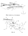
- upper lateral part of a motor vehicle structure is meant here the structural part which delimits the lateral part of the roof (or roof) on one of the two lateral (or longitudinal) sides of a motor vehicle and which located at the level of the upper part of a side door (see figure 1 ).
- motor vehicles 1 comprise a structure whose two opposite upper lateral parts 2 are equipped with a longitudinal bar 3.
- Each longitudinal bar 3 generally has a cross section of varied shape and is secured to one of the two upper lateral parts 3 by welding or screwing.
- the roof bars 4 are accessories that are adapted to be reported between the two longitudinal bars 3 and fixed on these bars via anchoring devices 5 which must generally be previously mounted on the ends of the roof bars.
- the roof bars 4 are used to support different types of objects such as a roof box, surf bike racks, skis, etc.
- the device comprises, on the free end of the roof bar, a fixed jaw and a movable jaw disposed opposite the fixed part being movable in translation relative to the fixed part, the jaws being adapted to at least partially enclose a section of the longitudinal bar, and clamping means of the jaws on the longitudinal bar.
- the transverse bars can be arranged in different configurations along the longitudinal bars.
- Blocking in position is ensured by simply pinching the longitudinal bar between the two jaws.
- This device does not guarantee optimum shock resistance and tear resistance in accordance with the standards in force.
- the invention aims to provide an anchoring device for securely fixing a roof bar end on a longitudinal bar secured to an upper side portion of a motor vehicle structure.
- a device for anchoring a roof bar end on a longitudinal bar secured to an upper lateral part of a vehicle structure part substantially parallel to a longitudinal direction of the latter said device comprising a fixed jaw and a movable jaw disposed facing the fixed jaw being movable relative to the fixed jaw to be able to grip at least partially a section of the longitudinal bar, and clamping means of the movable jaw on the longitudinal bar
- the device being characterized in that it comprises at least first anchoring means comprising at least one body secured to the roof bar ending in a first nozzle defining a bearing surface of the fixed jaw substantially conforming to the shape of the longitudinal bar, said body supporting displacement of the movable jaw, one end protrudes from the body s to come opposite the first nozzle, and in that the device comprises at least second anchoring means comprising means forming a stop, formed on or in the longitudinal bar; the end portion of the second nose of the first anchoring means being shaped to be adapted to cooperating with said abutment second anchoring means under
- the body rotatably supports a lever defining the movable jaw and whose displacement is rotated about a fixed fulcrum of the body under the effect of the clamping means.
- the clamping means comprise a screw whose head is abutting on the roof bar and whose threaded portion cooperates with a nut means coupled in rotation with the lever.
- the body supports in translation a jaw defining the movable jaw and whose displacement is in translation in the body under the effect of the clamping means.
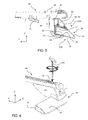
- the cross section of the longitudinal bar is delimited by a flat inner edge, extending by an adjacent lower plane edge, and a partially convex upper edge connecting the lower edge to the inner edge.
- the bearing surface of the first nozzle is shaped to be able to fit at least partially the inner edge and the upper edge of the longitudinal bar, and in that the second nozzle is shaped to be able to conform to less partially the lower edge of the longitudinal bar; the end portion of the second nozzle being bent to be able to cooperate with a stop formed in the lower edge of the longitudinal bar.
- the stop defines a generally rectangular counterbore whose large dimension extends in the longitudinal direction, centered on the lower edge of the longitudinal bar.
- the invention also proposes a roof bar comprising an access opening for the clamping means of the anchoring device as described above.
- the invention also proposes a longitudinal bar capable of being secured to an upper lateral part of a vehicle structure part, substantially parallel to a longitudinal direction of the latter, comprising a stop corresponding to that of the second anchoring means of the anchoring device as described above.
- the invention also provides a body adapted to be secured to the end of a roof bar as described above, said body belonging to the first anchoring means of the anchoring device as described above.
- the invention also proposes a motor vehicle comprising at least one pair of longitudinal bars as described above, at least one roof bar as described above and an anchoring device as described above.
- the motor vehicle is a car (possibly cut type). But, the invention is not limited to this type of motor vehicle. It relates in fact to any type of motor vehicle having a roof defined at each of its opposite lateral parts by an upper side of the structure to which is secured in a robust manner a pair of longitudinal bars.
- longitudinal direction X the direction which is substantially parallel to the side doors of the vehicle and therefore to the upper lateral parts of the structure
- transverse direction Y the direction which is substantially perpendicular to the side doors of the vehicle and therefore to the longitudinal direction X
- vertical direction Z the direction which is substantially perpendicular to the longitudinal direction X and transverse Y.
- the cross section of the longitudinal bar 30, visible on the figures 2 , 5 and 6 is delimited by an inner edge 31 substantially flat and vertical, extending by an adjacent lower flat edge 32, extending relative to the vertical inner edge 31 towards the outside of the vehicle 1 with an angle of between 90 ° and 110 ° , typically 105 °, relative to the vertical inner edge 31, and an upper edge 33 connecting the lower edge 32 to the inner edge 31.
- This edge 33 is first convex, opposite the inner edge 31, and then gradually becomes parallel at the lower edge 32 by approaching the inner edge 31 in the manner of a so-called "airfoil" profile.
- an anchoring device 50 which comprises first and second anchoring means 50A, 50B respectively distributed on the roof bar 40 and on the longitudinal bar 30.
- the main body 51 of the first anchoring means 50A of the anchoring device 50 is mounted in translation on a guide rail 41 formed on the inner face of the end of the roof bar 40.
- This rail 41 of determined length and open towards the outside of the bar 40, makes it possible to adjust the first anchoring means 50A to the spacing between the two longitudinal bars 30.
- the outer part of the main body 51, along Y, (right in the figures) defines a fixed jaw 52 whose free end is shaped as a first spout 53, to be able to fit at least partially the vertical inner edge 31 and the upper edge 33 of the longitudinal bar 30.
- the main body 51 rotatably supports a movable jaw 54 whose free end is shaped to define a second spout 55, facing the first spout 53.
- the movable jaw 54 is preferably metallic in order to be able to withstand the mechanical stresses, in particular of tearing and impact.
- the end portion of the second spout 55 is bent in the shape of a hook 56 so as to be able to cooperate with the second anchoring means 50B arranged under the longitudinal bar 30.
- These second anchoring means 50B according to the invention are materialized by an opening 34 formed in the lower edge 32 of the longitudinal bar 30 having at least two longitudinal stops and at least two transverse stops capable of ensuring the locking X and Y of the roof bar 40 on the longitudinal bar 30.
- the opening 34 defines a rectangular generally oblong facing, the large dimension of which extends in the longitudinal direction X, being centered on the lower edge 32 of the longitudinal bar 30. edges of the countersink 34 define stops for the bent portion 56 of the second spout 55.
- the opening may be replaced by at least one protuberance formed integrally with the lower edge 32 of the longitudinal bar 30 to define a stop X, projecting under the lower edge 32 of the longitudinal bar 30.
- a piece of flexible material 60 is attached inside the first spout 53 to protect the longitudinal bar 30 and absorb vibration.
- This piece 60 extends outside the second spout 55, downwards, along Z, towards the end of the second spout 55, to define a flat tongue 61 of greater width than that of the end of the second spout 55 .
- the length of the tongue 61 is determined to be able to interpose between the second spout 55 and the lower edge 32 of the longitudinal bar 30 when the roof bar 40 is assembled on the longitudinal bar 30.
- the free end of the tongue 61 is provided with an opening 62 of generally rectangular or oblong shape, adapted to be disposed facing the counterbore 34 of the longitudinal bar 30 and to be traversed from side to side. part by the curved portion 56 of the second spout 55, at the time of clamping the movable jaw 54 against the longitudinal bar 30.
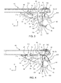
- a movable jaw clamping mechanism 54 is hereinafter described with reference to Figures 3 to 6 .
- the movable jaw portion 54 comprises a lever 70, extending inside the body 51 in the YZ plane, the two lever arms 71 and 72 extend in two opposite directions along Y, on either side of a fixed fulcrum 73 materialized by a projection protruding inside the upper part of the body 51.
- the first short arm 71 is disposed to the left of the fixed fulcrum 73 and the second, long arm 72 terminating in the second curved end plate 55 is disposed to the right of the fixed fulcrum 73 , referring to the orientation of Figures 3 to 6 .
- the second arm 72 comprises, starting from the fixed support point 73, a first section 721 extending in a first direction deviating substantially from an angle of approximately 10 ° from the horizontal direction along Y to the lower part of the body 51.
- the first section 721 is extended by a second section 722 of the same length, via a first bent portion 720, extending in a second direction deviating substantially from an angle of about 10 ° of the vertical direction along Z, to the outer part of the body 51 (to the right in the figures).
- the second section 722 is extended by a third section 723 extending in the same first direction, via a second bent portion 724, with the same angle with respect to the horizontal direction along Y, towards the lower part of the body 51.
- the third section 723 protrudes from the lower part of the body 51 and defines the second spout 55, able to come into contact with the lower edge 32 of the longitudinal bar 30.
- the free end 710 of the first lever arm 71 protrudes from the upper part of the body 51 through an opening 42 which is driven close to the fixed bearing point 73 (to the left of the fixed fulcrum). 73 in the figures). This opening 42 can wedge the lever 70 in the X and Y directions.
- the lever 70 (and thus the movable jaw 54) is held suspended in the body 51 by a screw 80 passing right through an opening 57 formed in the upper wall of the body 51, opposite the first bent portion 720 of the second arm lever 72.
- the screw head 81 hexagonal hollow or Torx type (the Torx screw is a solution to limit the risk of theft), is supported on the rail guide 41 and its threaded portion 82 through the opening 57 formed in the upper wall of the body 51.
- the lower end of the threaded portion 82 of the screw 80 cooperates with a threaded hole 90 of vertical axis Z, forming a nut , formed in a cylindrical rod 91 of circular section extending along X.
- the rod 91 is rotatably mounted in the first bent portion 720 of the second arm 72 to form a pivot connection.
- the assembly consisting of the threaded portion 82 and the nut-rod 90-91 form a worm system (helical linkage) and the mechanical connection between the rod 90 and the second arm 72 forms a pivot-type connection.
- the combination of the helical and pivot mechanical links defines a second fulcrum for the lever 70.
- the tightening of the screw 80 causes the second lever arm 72 upwards along Z, which pivots around the first fulcrum 73 anti-clockwise; the pivoting being authorized by the pivot connection.
- the screw head 81 is accessible through an opening 43 formed in the upper face of the roof bar 40, facing the screw head 80.
- the dimensions of the opening 43 are determined to take account of the movement of the body X 51 of the anchoring device on the rail 41 of the roof bar 40.
- the rotational movement of the second lever arm 72 is limited, in the lower part of the body 51, by two vertical walls or ribs 58 and 59, integral with the body 51 to define respectively two travel stops for the second section 722. second lever arm 72.
- the tightening of the screw 80 makes it possible to bring the second spout 55 closer to the lower edge 32 of the longitudinal bar 30 ensuring the introduction of the part curved end 56 of the second spout 55 inside the countersink 34 of the longitudinal bar 30.
- the movable jaw 54 then defines a movable jaw like that of a vice, the nut being then a simple tapped hole inside the bit. The fulcrum is then no longer necessary.
Landscapes
- Engineering & Computer Science (AREA)
- Mechanical Engineering (AREA)
- Body Structure For Vehicles (AREA)
- Dowels (AREA)
Abstract
Dispositif d'ancrage (50) d'une extrémité de barre de toit (40) sur une barre longitudinale (30), caractérisé en ce qu'il comporte au moins un premier moyens d'ancrage (50A) comportant au moins un corps (51) solidarisé à la barre de toit (40) se terminant par un premier bec définissant une surface d'appui (53) de la mâchoire fixe (52) épousant sensiblement la forme de la barre longitudinale (30), ledit corps (51) supportant à déplacement la mâchoire mobile (54) dont une extrémité (55) fait saillie du corps (51) pour venir en regard du premier bec (53), et en ce que le dispositif (50) comporte au moins des seconds moyens d'ancrage (50B) comportant des moyens formant butée (34), ménagés sur ou dans la barre longitudinale (30) ; la partie extrême (56) du second bec (55) des premiers moyens d'ancrage (50A) étant conformée pour être apte à coopérer avec ladite butée (34) des seconds moyens d'ancrage (50B) sous l'effet de moyens de serrage (80) couplés mécaniquement à la barre de toit et la mâchoire mobile (54), pour assurer le blocage de la barre de toit (40) sur la barre longitudinale (30).Anchoring device (50) for a roof bar end (40) on a longitudinal bar (30), characterized in that it comprises at least one first anchoring means (50A) comprising at least one body ( 51) secured to the roof bar (40) terminating in a first nose defining a bearing surface (53) of the fixed jaw (52) substantially conforming to the shape of the longitudinal bar (30), said body (51) movably supporting the movable jaw (54), one end (55) of which protrudes from the body (51) to face the first spout (53), and in that the device (50) comprises at least second means of anchorage (50B) having abutment means (34) provided on or in the longitudinal bar (30); the end portion (56) of the second nose (55) of the first anchoring means (50A) being shaped to be able to cooperate with said stop (34) of the second anchoring means (50B) under the effect of means of clamping mechanism (80) mechanically coupled to the roof bar and the movable jaw (54) for locking the roof bar (40) on the longitudinal bar (30).
Description
L'invention concerne les dispositifs permettant d'ancrer une extrémité d'une barre de toit (ou barre transversale) sur une barre longitudinale solidarisée à une partie latérale supérieure d'une structure de véhicule automobile.The invention relates to devices for anchoring an end of a roof bar (or crossbar) on a longitudinal bar secured to an upper side portion of a motor vehicle structure.
Elle concerne également une barre de toit transversale et une barre longitudinale mettant en oeuvre ledit dispositif d'ancrage.It also relates to a transverse roof bar and a longitudinal bar implementing said anchoring device.
On entend ici par « partie latérale supérieure d'une structure de véhicule automobile » la partie de structure qui délimite la partie latérale du toit (ou pavillon) sur l'un des deux côtés latéraux (ou longitudinaux) d'un véhicule automobile et qui se trouve située au niveau de la partie supérieure d'une portière latérale (voir
Comme le sait l'homme de l'art, et comme illustré sur la
Les barres de toit 4 sont des accessoires qui sont aptes à être rapportés entre les deux barres longitudinales 3 et fixés sur ces barres via des dispositifs d'ancrage 5 qui doivent généralement être préalablement montés sur les extrémités des barres de toit.The
Les barres de toit 4 sont utilisées pour supporter différents types d'objet tels qu'un coffre de toit, des supports de vélo de surf, de skis, etc.The
Elles doivent répondre à certaines normes de sécurité quant à leur résistance mécanique : poids maximal admissible, résistance à l'arrachement, aux chocs, ...They must meet certain safety standards as to their mechanical strength: maximum permissible weight, resistance to tearing, shocks, etc.
On connaît notamment du document
Selon cet agencement, le dispositif comporte, sur l'extrémité libre de la barre de toit, une mâchoire fixe et une mâchoire mobile disposée en regard de la partie fixe en étant mobile en translation par rapport à la partie fixe, les mâchoires étant aptes à enserrer au moins partiellement une section de la barre longitudinale, et des moyens de serrage des mâchoires sur la barre longitudinale. Toujours selon cet agencement, les barres transversales peuvent être disposées suivant différentes configurations le long des barres longitudinales.According to this arrangement, the device comprises, on the free end of the roof bar, a fixed jaw and a movable jaw disposed opposite the fixed part being movable in translation relative to the fixed part, the jaws being adapted to at least partially enclose a section of the longitudinal bar, and clamping means of the jaws on the longitudinal bar. Still according to this arrangement, the transverse bars can be arranged in different configurations along the longitudinal bars.
Le blocage en position est assuré par simple pincement de la barre longitudinale entre les deux mâchoires.Blocking in position is ensured by simply pinching the longitudinal bar between the two jaws.
Ce dispositif ne garantit pas une tenue aux chocs et à l'arrachement optimale conforme aux normes en vigueur.This device does not guarantee optimum shock resistance and tear resistance in accordance with the standards in force.
L'invention a pour but d'offrir un dispositif d'ancrage destiné à fixer de manière robuste, une extrémité de barre de toit sur une barre longitudinale solidarisée à une partie latérale supérieure d'une structure de véhicule automobile.The invention aims to provide an anchoring device for securely fixing a roof bar end on a longitudinal bar secured to an upper side portion of a motor vehicle structure.
Elle propose à cet effet un dispositif d'ancrage d'une extrémité de barre de toit sur une barre longitudinale solidarisée à une partie latérale supérieure d'une partie de structure de véhicule sensiblement parallèle à une direction longitudinale de ce dernier, ledit dispositif comportant une mâchoire fixe et une mâchoire mobile disposée en regard de la mâchoire fixe en étant mobile par rapport à la mâchoire fixe pour être apte à enserrer au moins partiellement une section de la barre longitudinale, et des moyens de serrage de la mâchoire mobile sur la barre longitudinale, le dispositif étant caractérisé en ce qu'il comporte au moins des premiers moyens d'ancrage comportant au moins un corps solidarisé à la barre de toit se terminant par un premier bec définissant une surface d'appui de la mâchoire fixe épousant sensiblement la forme de la barre longitudinale, ledit corps supportant à déplacement la mâchoire mobile dont une extrémité fait saillie du corps pour venir en regard du premier bec, et en ce que le dispositif comporte au moins des seconds moyens d'ancrage comportant des moyens formant butée, ménagés sur ou dans la barre longitudinale ; la partie extrême du second bec des premiers moyens d'ancrage étant conformée pour être apte à coopérer avec ladite butée des seconds moyens d'ancrage sous l'effet de moyens de serrage couplés mécaniquement à la barre de toit et la mâchoire mobile, pour assurer le blocage de la barre de toit sur la barre longitudinale.It proposes for this purpose a device for anchoring a roof bar end on a longitudinal bar secured to an upper lateral part of a vehicle structure part substantially parallel to a longitudinal direction of the latter, said device comprising a fixed jaw and a movable jaw disposed facing the fixed jaw being movable relative to the fixed jaw to be able to grip at least partially a section of the longitudinal bar, and clamping means of the movable jaw on the longitudinal bar , the device being characterized in that it comprises at least first anchoring means comprising at least one body secured to the roof bar ending in a first nozzle defining a bearing surface of the fixed jaw substantially conforming to the shape of the longitudinal bar, said body supporting displacement of the movable jaw, one end protrudes from the body s to come opposite the first nozzle, and in that the device comprises at least second anchoring means comprising means forming a stop, formed on or in the longitudinal bar; the end portion of the second nose of the first anchoring means being shaped to be adapted to cooperating with said abutment second anchoring means under the effect of clamping means mechanically coupled to the roof bar and the movable jaw, to ensure the locking of the roof bar on the longitudinal bar.
Selon un premier mode de réalisation, le corps supporte à rotation un levier définissant la mâchoire mobile et dont le déplacement se fait à rotation autour d'un point d'appui fixe du corps sous l'effet des moyens de serrage.According to a first embodiment, the body rotatably supports a lever defining the movable jaw and whose displacement is rotated about a fixed fulcrum of the body under the effect of the clamping means.
Selon une caractéristique du premier mode de réalisation, les moyens de serrage comportent une vis dont la tête est en butée sur la barre de toit et dont la partie filetée coopère avec un moyen formant écrou couplé en rotation avec le levier.According to a feature of the first embodiment, the clamping means comprise a screw whose head is abutting on the roof bar and whose threaded portion cooperates with a nut means coupled in rotation with the lever.
Selon un deuxième mode de réalisation, le corps supporte à translation un mors définissant la mâchoire mobile et dont le déplacement se fait à translation dans le corps sous l'effet des moyens de serrage.According to a second embodiment, the body supports in translation a jaw defining the movable jaw and whose displacement is in translation in the body under the effect of the clamping means.
Selon une caractéristique commune aux premier et deuxième modes de réalisation, la section transversale de la barre longitudinale est délimitée par un bord intérieur plan, se prolongeant par un bord inférieur adjacent plan, et un bord supérieur partiellement convexe reliant le bord inférieur au bord intérieur.According to a characteristic common to the first and second embodiments, the cross section of the longitudinal bar is delimited by a flat inner edge, extending by an adjacent lower plane edge, and a partially convex upper edge connecting the lower edge to the inner edge.
Selon une autre caractéristique, la surface d'appui du premier bec est conformée pour être apte à épouser au moins partiellement le bord intérieur et le bord supérieur de la barre longitudinale, et en ce que le second bec est conformé pour être apte à épouser au moins partiellement le bord inférieur de la barre longitudinale ; la partie extrême du second bec étant recourbée pour être apte à coopérer avec une butée ménagée dans le bord inférieur de la barre longitudinale.According to another characteristic, the bearing surface of the first nozzle is shaped to be able to fit at least partially the inner edge and the upper edge of the longitudinal bar, and in that the second nozzle is shaped to be able to conform to less partially the lower edge of the longitudinal bar; the end portion of the second nozzle being bent to be able to cooperate with a stop formed in the lower edge of the longitudinal bar.
Selon une caractéristique, la butée définit un lamage de forme générale rectangulaire dont la grande dimension s'étend suivant la direction longitudinale, centré sur le bord inférieur de la barre longitudinale.According to one characteristic, the stop defines a generally rectangular counterbore whose large dimension extends in the longitudinal direction, centered on the lower edge of the longitudinal bar.
L'invention propose également une barre de toit comportant une ouverture d'accès pour les moyens de serrage du dispositif d'ancrage selon tel que décrit ci-dessus.The invention also proposes a roof bar comprising an access opening for the clamping means of the anchoring device as described above.
L'invention propose également une barre longitudinale apte à être solidarisée à une partie latérale supérieure d'une partie de structure de véhicule, sensiblement parallèle à une direction longitudinale de ce dernier, comportant une butée conforme à celle des seconds moyens d'ancrage du dispositif d'ancrage tel que décrit ci-dessus.The invention also proposes a longitudinal bar capable of being secured to an upper lateral part of a vehicle structure part, substantially parallel to a longitudinal direction of the latter, comprising a stop corresponding to that of the second anchoring means of the anchoring device as described above.
L'invention propose également un corps apte à être solidarisé sur l'extrémité d'une barre de toit tel que décrite ci-dessus, ledit corps appartenant aux premiers moyens d'ancrage du dispositif d'ancrage tel que décrit ci-dessus.The invention also provides a body adapted to be secured to the end of a roof bar as described above, said body belonging to the first anchoring means of the anchoring device as described above.
L'invention propose également un véhicule automobile comportant au moins une paire de barres longitudinales telles que décrites ci-dessus, au moins une barre de toit tel que décrit ci-dessus et un dispositif d'ancrage tel que décrit ci-dessus.The invention also proposes a motor vehicle comprising at least one pair of longitudinal bars as described above, at least one roof bar as described above and an anchoring device as described above.
L'invention propose enfin, un procédé d'assemblage d'une barre de toit telle que décrite ci-dessus, sur une barre longitudinale telle que décrite ci-dessus mettant en oeuvre le dispositif d'ancrage tel que décrit ci-dessus, caractérisé en ce qu'il consiste :
- à amener en butée, le premier bec contre un bord intérieur de la barre longitudinale ; le second bec passant sous son bord inférieur ;
- à actionner les moyens de serrage pour amener progressivement le second bec contre le bord inférieur de la barre de toit ; la partie recourbée du second bec pénétrant progressivement à l'intérieur du lamage ménagé dans le bord inférieur de la barre longitudinale jusqu'au blocage complet de l'assemblage.
- to abut the first nose against an inner edge of the longitudinal bar; the second bill passing under its lower edge;
- actuating the clamping means to gradually bring the second nose against the lower edge of the roof bar; the bent portion of the second beak gradually penetrating inside the countersink formed in the lower edge of the longitudinal bar until complete blocking of the assembly.
D'autres caractéristiques et avantages de l'invention apparaîtront à l'examen de la description détaillée ci-après, et des dessins annexés, sur lesquels :
- la
figure 1 , déjà décrite, illustre partiellement un toit d'un véhicule automobile équipé de barres longitudinales recevant une paire de barres de toit selon l'état de la technique ; - la
figure 2 illustre, selon une vue d'ensemble en perspective, un dispositif d'ancrage selon l'invention, avant solidarisation d'une barre de toit avec une barre longitudinale ; - la
figure 3 illustre, dans une vue en coupe transversale, une partie du dispositif d'ancrage selon l'invention dans une première position extrême ; - la
figure 4 illustre, dans une vue en coupe transversale, la même partie du dispositif d'ancrage selon l'invention dans une deuxième position extrême ; - la
figure 5 illustre, dans une vue en coupe transversale, le dispositif d'ancrage complet selon l'invention, dans la deuxième position extrême correspondant à la position dans laquelle l'ancrage de la barre de toit sur la barre longitudinale est assuré ; et - la
figure 6 illustre, par une vue en perspective, l'étape de serrage du procédé d'assemblage selon l'invention.
- the
figure 1 , already described, partially illustrates a roof of a motor vehicle equipped with longitudinal bars receiving a pair of roof bars according to the state of the art; - the
figure 2 illustrates, in an overall perspective view, an anchoring device according to the invention, before securing a roof bar with a longitudinal bar; - the
figure 3 illustrates, in a cross-sectional view, a portion of the anchoring device according to the invention in a first extreme position; - the
figure 4 illustrates, in a cross-sectional view, the same part of the anchoring device according to the invention in a second extreme position; - the
figure 5 illustrates, in a cross-sectional view, the complete anchoring device according to the invention, in the second extreme position corresponding to the position in which the anchoring of the roof bar on the longitudinal bar is ensured; and - the
figure 6 illustrates, in a perspective view, the clamping step of the assembly method according to the invention.
Sur les figures, les mêmes éléments sont désignés par les mêmes références numériques.In the figures, the same elements are designated by the same reference numerals.
Les dessins des figures sont orientés suivant un référentiel orthonormé XYZ généralement utilisé dans le domaine de l'automobile pour repérer le véhicule ou des parties du véhicule dans l'espace.The drawings of the figures are oriented according to an XYZ orthonormal frame of reference generally used in the field of the automobile to locate the vehicle or parts of the vehicle in space.
Dans ce qui suit, on considère, à titre d'exemple non limitatif, que le véhicule automobile est une voiture (éventuellement de type coupé). Mais, l'invention n'est pas limitée à ce type de véhicule automobile. Elle concerne en effet tout type de véhicule automobile comportant un toit délimité au niveau de chacune de ses parties latérales opposées par une partie latérale supérieure de structure à laquelle est solidarisée de manière robuste une paire de barres longitudinales.In the following, we consider, by way of non-limiting example, that the motor vehicle is a car (possibly cut type). But, the invention is not limited to this type of motor vehicle. It relates in fact to any type of motor vehicle having a roof defined at each of its opposite lateral parts by an upper side of the structure to which is secured in a robust manner a pair of longitudinal bars.
Par ailleurs, dans ce qui suit, on appellera « direction longitudinale X » la direction qui est sensiblement parallèle aux portières latérales du véhicule et donc aux parties latérales supérieures de la structure, « direction transversale Y » la direction qui est sensiblement perpendiculaire aux portières latérales du véhicule et donc à la direction longitudinale X, et « direction verticale Z » la direction qui est sensiblement perpendiculaire aux directions longitudinale X et transversale Y.Furthermore, in what follows, will be called "longitudinal direction X" the direction which is substantially parallel to the side doors of the vehicle and therefore to the upper lateral parts of the structure, "transverse direction Y" the direction which is substantially perpendicular to the side doors of the vehicle and therefore to the longitudinal direction X, and "vertical direction Z" the direction which is substantially perpendicular to the longitudinal direction X and transverse Y.
La description de la section transversale d'une barre longitudinale 30 selon l'invention est donnée ci-dessous telle que positionnée sur le toit du véhicule 1. Les termes « intérieur », « extérieur », « supérieur » et « inférieur » sont donc à comprendre dans cet environnement.The description of the cross section of a
La section transversale de la barre longitudinale 30, visible sur les
L'assemblage de la barre de toit 40 avec la barre longitudinale 30 est réalisé par un dispositif d'ancrage 50 selon l'invention qui comporte des premier et second moyens d'ancrage 50A, 50B respectivement répartis sur la barre de toit 40 et sur la barre longitudinale 30.The assembly of the
De manière connue, le corps principal 51 des premiers moyens d'ancrage 50A du dispositif d'ancrage 50 selon l'invention est monté à translation sur un rail de guidage 41 ménagé sur la face intérieure de l'extrémité de la barre de toit 40. Ce rail 41, de longueur déterminée et ouvert vers l'extérieur de la barre 40, permet d'ajuster les premiers moyens d'ancrage 50A à l'écartement entre les deux barres longitudinales 30.In known manner, the
La partie extérieure du corps principal 51, suivant Y, (à droite sur les figures) définit une mâchoire fixe 52 dont l'extrémité libre est conformée en un premier bec 53, pour être apte à épouser au moins partiellement le bord intérieur vertical 31 et le bord supérieur 33 de la barre longitudinale 30.The outer part of the
Le corps principal 51 supporte à rotation une mâchoire mobile 54 dont l'extrémité libre est conformée pour définir un second bec 55, venant en regard du premier bec 53.The
La mâchoire mobile 54 est de préférence métallique pour pouvoir supporter les contraintes mécaniques, notamment d'arrachement et de choc.The
La partie extrême du second bec 55 est recourbée en forme de crochet 56 de manière à être apte à coopérer avec les seconds moyens d'ancrage 50B disposés sous la barre longitudinale 30.The end portion of the
Ces seconds moyens d'ancrage 50B selon l'invention sont matérialisés par une ouverture 34 ménagée dans le bord inférieur 32 de la barre longitudinale 30 comportant au moins deux butées longitudinales et au moins deux butées transversales aptes à assurer le blocage en X et en Y de la barre de toit 40 sur la barre longitudinale 30.These second anchoring means 50B according to the invention are materialized by an
Dans le mode de réalisation décrit, l'ouverture 34 définit un lamage de forme générale rectangulaire, ou oblongue, dont la grande dimension s'étend suivant la direction longitudinale X, en étant centré sur le bord inférieur 32 de la barre longitudinale 30. Les bords du lamage 34 définissent des butées pour la partie recourbée 56 du second bec 55.In the embodiment described, the
A titre de variante, non représentée, l'ouverture peut être remplacée par au moins une excroissance venue de matière avec le bord inférieur 32 de la barre longitudinale 30 pour définir une butée en X, faisant saillie sous le bord inférieur 32 de la barre longitudinale 30.Alternatively, not shown, the opening may be replaced by at least one protuberance formed integrally with the
Une pièce en matériau souple 60, de type caoutchouc, est rapportée à l'intérieur du premier bec 53 pour protéger la barre longitudinale 30 et absorber les vibrations.A piece of
Cette pièce 60 se prolonge en dehors du second bec 55, vers le bas, selon Z, en direction de l'extrémité du second bec 55, pour définir une languette plate 61 de plus grande largeur que celle de l'extrémité du second bec 55.This
La longueur de la languette 61 est déterminée pour pourvoir s'interposer entre le second bec 55 et le bord inférieur 32 de la barre longitudinale 30 quand la barre de toit 40 est assemblée sur la barre longitudinale 30.The length of the
Dans le mode de réalisation décrit, l'extrémité libre de la languette 61 est munie d'une ouverture 62 de forme générale rectangulaire ou oblongue, apte à être disposée en regard du lamage 34 de la barre longitudinale 30 et à être traversée de part en part par la partie recourbée 56 du second bec 55, au moment du serrage de la mâchoire mobile 54 contre la barre longitudinale 30.In the embodiment described, the free end of the
Un mécanisme de serrage de mâchoire mobile 54 est décrit ci-après en référence aux
Selon l'invention, la partie de mâchoire mobile 54 comporte un levier 70, s'étendant à l'intérieur du corps 51 dans le plan YZ, dont les deux bras de levier 71 et 72 s'étendent selon deux directions opposées selon Y, de part et d'autre d'un point d'appui fixe 73 matérialisé par une protubérance faisant saillie à l'intérieur de la partie supérieure du corps 51.According to the invention, the
Le premier bras, court, 71 est disposé à gauche du point d'appui fixe 73 et le deuxième bras, long, 72 se terminant par le second bec 55 à partie extrême recourbée 56, est disposé à droite du point d'appui fixe 73, en se référant à l'orientation des
Le deuxième bras 72 comporte, en partant du point d'appui fixe 73, un premier tronçon 721 s'étendant selon une première direction s'écartant sensiblement d'un angle d'environ 10°, de la direction horizontale selon Y, vers la partie inférieur du corps 51. Le premier tronçon 721 se prolonge par un deuxième tronçon 722 de même longueur, via une première partie coudée 720, en s'étendant selon une deuxième direction s'écartant sensiblement d'un angle d'environ 10° de la direction verticale selon Z, vers la partie extérieure du corps 51 (vers la droite sur les figures). Le deuxième tronçon 722 se prolonge par un troisième tronçon 723 s'étendant selon la même première direction, via une deuxième partie coudée 724, avec le même angle par rapport à la direction horizontale selon Y, vers la partie inférieur du corps 51. Le troisième tronçon 723 fait saillie de la partie inférieure du corps 51 et définit le second bec 55, apte à venir en contact avec le bord inférieur 32 de la barre longitudinale 30.The
L'extrémité libre 710 du premier bras de levier 71 fait quant à elle saillie de la partie supérieure du corps 51, au travers d'une ouverture 42 managée à proximité du point d'appui fixe 73 (à gauche du point d'appui fixe 73 sur les figures). Cette ouverture 42 permet de caler le levier 70 selon les directions X et Y.The
Le levier 70 (et donc la mâchoire mobile 54) est maintenu suspendu dans le corps 51 par une vis 80 traversant de part en part une ouverture 57 ménagée dans la paroi supérieure du corps 51, en regard de la première partie coudée 720 du deuxième bras de levier 72.The lever 70 (and thus the movable jaw 54) is held suspended in the
La tête de vis 81, de type hexagonale creuse ou à empreinte Torx (la vis Torx est une solution pour limiter le risque de vol), prend appui sur le rail de guidage 41 et sa partie filetée 82 traverse l'ouverture 57 ménagée dans la paroi supérieure du corps 51. L'extrémité inférieure de la partie filetée 82 de la vis 80 coopère avec un trou taraudé 90 d'axe vertical selon Z, formant écrou, ménagé dans une tige cylindrique 91 de section circulaire s'étendant selon X. La tige 91 est montée à rotation dans la première partie coudée 720 du deuxième bras 72 pour former une liaison pivot.The
L'ensemble constitué de la partie filetée 82 et de la tige-écrou 90-91 forme un système de vis sans fin (liaison hélicoïdale) et la liaison mécanique entre la tige 90 et le deuxième bras 72 forme une liaison de type pivot. La combinaison des liaisons mécaniques hélicoïdale et pivot définit un deuxième point d'appui pour le levier 70.The assembly consisting of the threaded
Le serrage de la vis 80 entraine le deuxième bras de levier 72 vers le haut suivant Z, lequel pivote autour du premier point d'appui 73 selon le sens anti horaire ; le pivotement étant autorisé par la liaison pivot.The tightening of the
La tête de vis 81 est accessible par une ouverture 43 ménagée dans la face supérieure de la barre de toit 40, en regard de la tête de vis 80. Les dimensions de l'ouverture 43 sont déterminées pour tenir compte du débattement en X du corps 51 du dispositif d'ancrage sur le rail 41 de la barre de toit 40.The
Le débattement en rotation du deuxième bras de levier 72 est limité, dans la partie inférieure du corps 51, par deux parois ou nervures verticales 58 et 59, venues de matière avec le corps 51 pour définir respectivement deux butées de débattement pour le deuxième tronçon 722 du deuxième bras de levier 72.The rotational movement of the
Quand le premier bec 53 est positionné sur les bords intérieur 31 et supérieur 33 de la barre longitudinale 30, le serrage de la vis 80 permet de rapprocher le second bec 55 du bord inférieur 32 de la barre longitudinale 30 assurant l'introduction de la partie extrême recourbée 56 du second bec 55 à l'intérieur du lamage 34 de la barre longitudinale 30.When the first spout 53 is positioned on the inner 31 and upper 33 edges of the
A l'inverse, le desserrage de la vis 80 entraine la désolidarisation du second bec 55 de la barre longitudinale 30 et donc le retrait de la partie recourbée 56 du lamage 34.Conversely, the loosening of the
A titre de variante, et en considérant que l'angle de pivot peut être minimal, voire supprimé, on peut remplacer la liaison pivot par une simple liaison en translation verticale selon Z. Dans cette variante, non représentée, la mâchoire mobile 54 définit alors un mors mobile comme celui d'un étau, l'écrou étant alors un simple trou taraudé à l'intérieur du mors. Le point d'appui n'est alors plus nécessaire.Alternatively, and considering that the pivot angle can be If this variant is not shown, the
Le procédé d'assemblage d'une barre de toit 40 sur une barre longitudinale 30 mettant en oeuvre le dispositif d'ancrage 50 selon l'invention consiste de manière simple :
- à amener en butée, le bec 53 de la partie de mâchoire fixe 52 contre les bords intérieur 31 et supérieur 33 de la barre longitudinale 30 ; en ayant préalablement desserré la vis de serrage 80 ;
- à positionner le bec 55 de la partie de mâchoire mobile 54, en regard du lamage 34 du bord inférieur 32 de la barre longitudinale 30 en ayant préalablement interposé l'extrémité de la languette 61 entre le bec 55 de la partie de mâchoire mobile 54 et le bord inférieur 32 de la barre longitudinale 30 ; la partie recourbée 56
traversant l'ouverture 62 de la languette 61 ; - à effectuer un serrage progressif de la vis 80 par la partie supérieure de la barre de toit 40, au moyen d'un outil de serrage 100 de type clé allène ou Torx ou tournevis, pour introduire progressivement la partie recourbée 56 à l'intérieur du lamage 34 ménagé dans le bord inférieur 32 de la barre longitudinale 30 jusqu'au blocage complet de l'assemblage.
- to bring into abutment the nose 53 of the fixed jaw portion 52 against the inner 31 and upper 33 edges of the
longitudinal bar 30; having previously loosened the clampingscrew 80; - to position the
nose 55 of themovable jaw portion 54, opposite thecountersink 34 of thelower edge 32 of thelongitudinal bar 30 having previously interposed the end of thetongue 61 between thenose 55 of themovable jaw portion 54 and thelower edge 32 of thelongitudinal bar 30; thecurved portion 56 passing through theopening 62 of thetongue 61; - to make a progressive tightening of the
screw 80 by the upper part of theroof bar 40, by means of aclamping tool 100 allen type key or torx or screwdriver, to gradually introduce thebent portion 56 inside thecountersink 34 formed in thelower edge 32 of thelongitudinal bar 30 until complete blocking of the assembly.
Claims (11)
Applications Claiming Priority (1)
| Application Number | Priority Date | Filing Date | Title |
|---|---|---|---|
| FR1454054A FR3020612B1 (en) | 2014-05-05 | 2014-05-05 | DEVICE FOR ANCHORING THE END OF A ROOF BAR FOR A MOTOR VEHICLE EQUIPPED WITH LONGITUDINAL ROOF BARS |
Publications (2)
| Publication Number | Publication Date |
|---|---|
| EP2942237A1 true EP2942237A1 (en) | 2015-11-11 |
| EP2942237B1 EP2942237B1 (en) | 2017-10-18 |
Family
ID=51168190
Family Applications (1)
| Application Number | Title | Priority Date | Filing Date |
|---|---|---|---|
| EP15165290.6A Active EP2942237B1 (en) | 2014-05-05 | 2015-04-27 | Device for anchoring a roof bar end for a motor vehicle provided with longitudinal roof bars |
Country Status (2)
| Country | Link |
|---|---|
| EP (1) | EP2942237B1 (en) |
| FR (1) | FR3020612B1 (en) |
Cited By (3)
| Publication number | Priority date | Publication date | Assignee | Title |
|---|---|---|---|---|
| EP3290273A1 (en) * | 2016-09-06 | 2018-03-07 | Bosal ACPS Holding 2 B.V. | Roof rack |
| CN108773327A (en) * | 2018-04-28 | 2018-11-09 | 浙江信基科技有限公司 | A kind of automobile luggage racks |
| US10766428B2 (en) | 2018-01-05 | 2020-09-08 | Ford Global Technologies, Llc | Rail system for roof rack fastening |
Families Citing this family (2)
| Publication number | Priority date | Publication date | Assignee | Title |
|---|---|---|---|---|
| US11577658B2 (en) | 2020-11-25 | 2023-02-14 | Plasman Us Holdco Llc | Crossmember assembly with a scotch yoke for an adjustable roof rack of a motor vehicle |
| US11299104B1 (en) | 2020-11-25 | 2022-04-12 | Dus Operating Inc. | Universal crossmember assembly for a roof rack of a motor vehicle |
Citations (4)
| Publication number | Priority date | Publication date | Assignee | Title |
|---|---|---|---|---|
| WO2008140379A1 (en) * | 2007-05-09 | 2008-11-20 | Thule Sweden Ab | Load carrying foot for clamping of a load carrier |
| EP2216204A1 (en) * | 2009-02-05 | 2010-08-11 | JAC Products Europe GmbH | Roof luggage holder for motor vehicles |
| WO2011102780A1 (en) * | 2010-02-18 | 2011-08-25 | Mont Blanc Industri Aktiebolag | Fastening assembly for a roof box |
| CN202669658U (en) | 2012-04-26 | 2013-01-16 | 周用强 | Car roof rack |
-
2014
- 2014-05-05 FR FR1454054A patent/FR3020612B1/en active Active
-
2015
- 2015-04-27 EP EP15165290.6A patent/EP2942237B1/en active Active
Patent Citations (4)
| Publication number | Priority date | Publication date | Assignee | Title |
|---|---|---|---|---|
| WO2008140379A1 (en) * | 2007-05-09 | 2008-11-20 | Thule Sweden Ab | Load carrying foot for clamping of a load carrier |
| EP2216204A1 (en) * | 2009-02-05 | 2010-08-11 | JAC Products Europe GmbH | Roof luggage holder for motor vehicles |
| WO2011102780A1 (en) * | 2010-02-18 | 2011-08-25 | Mont Blanc Industri Aktiebolag | Fastening assembly for a roof box |
| CN202669658U (en) | 2012-04-26 | 2013-01-16 | 周用强 | Car roof rack |
Cited By (3)
| Publication number | Priority date | Publication date | Assignee | Title |
|---|---|---|---|---|
| EP3290273A1 (en) * | 2016-09-06 | 2018-03-07 | Bosal ACPS Holding 2 B.V. | Roof rack |
| US10766428B2 (en) | 2018-01-05 | 2020-09-08 | Ford Global Technologies, Llc | Rail system for roof rack fastening |
| CN108773327A (en) * | 2018-04-28 | 2018-11-09 | 浙江信基科技有限公司 | A kind of automobile luggage racks |
Also Published As
| Publication number | Publication date |
|---|---|
| FR3020612B1 (en) | 2017-12-01 |
| EP2942237B1 (en) | 2017-10-18 |
| FR3020612A1 (en) | 2015-11-06 |
Similar Documents
| Publication | Publication Date | Title |
|---|---|---|
| EP2942237B1 (en) | Device for anchoring a roof bar end for a motor vehicle provided with longitudinal roof bars | |
| EP3145790B1 (en) | Steering column mechanism adjustable in depth with a retractable stopper | |
| EP2815151B1 (en) | Damping stop for a hinge, in particular for a hinge for the door of a vehicle | |
| FR2859676A1 (en) | CARRIER CARRIER HAVING A LATERAL OPENING OF THE CHASSIS AND A DOOR RIGIDIFYING THE CHASSIS | |
| EP3184379A1 (en) | Cap and driving arm for a wiping device for a motor vehicle | |
| FR2949804A1 (en) | HINGE AND METHOD OF OPERATION | |
| FR2796013A1 (en) | Adjustment mechanism for vehicle seat runner comprises endless screw mounted in nut housed in support, transverse plugs interposed between nut and support | |
| FR2943693A1 (en) | Barrier for controlling access of circulation path of e.g. toll lane, has rail contacted with re-hinging cam and pivoted around pivoting axis when rail is pivoted between lowered closing position and raised opening position | |
| FR2876959A1 (en) | OPENING DEVICE FOR MOTOR VEHICLE | |
| WO2012143474A1 (en) | Connection system for attaching a carrier device | |
| FR2952881A1 (en) | Windscreen wiper mechanism for front windscreen of motor vehicle, has blocking units comprising projections elastically engaged in orifices formed on support or sliding elements for rigidly connecting bearing to support elements | |
| EP2872718B1 (en) | Hinge of an automobile vehicle motor compartment hood | |
| EP3069936B1 (en) | Device forming a step of a motor vehicle | |
| EP3044020B1 (en) | Motor vehicle tailgate comprising a support frame and corresponding vehicle | |
| EP3626591B1 (en) | Method for attaching a rear vehicle shield on a rear crossmember | |
| EP3678894B1 (en) | Anchoring device for a removable seat on a motor vehicle floor | |
| WO2017187037A1 (en) | Vehicle door with reinforcer and vehicle comprising such a door | |
| FR2920467A1 (en) | Apron's end stop device for roller shutter of e.g. warehouse, has stop element positioned in support element for introducing stop unit in chamber of lateral end of final slat such that rod is parallel to longitudinal axis of slat | |
| FR2730254A1 (en) | Movable support for signalling panel | |
| WO2017046527A1 (en) | Two-position locking device for a backrest of a rear seat of a motor vehicle | |
| EP4313691A1 (en) | Interface for attaching an exterior vehicle fitting | |
| EP3882082A1 (en) | Vehicle with improved pivoting arm | |
| EP2366284B1 (en) | Anti-noise device for barrier with feeding rack | |
| FR2926314A1 (en) | Strike plate for e.g. left sliding side door locking device of motor vehicle, has extension forming stop for damping impact of latch against stop surface of plate when sliding side door is closed while latch is in displacement position | |
| FR2774609A1 (en) | Support for painting automobile bodywork |
Legal Events
| Date | Code | Title | Description |
|---|---|---|---|
| PUAI | Public reference made under article 153(3) epc to a published international application that has entered the european phase |
Free format text: ORIGINAL CODE: 0009012 |
|
| AK | Designated contracting states |
Kind code of ref document: A1 Designated state(s): AL AT BE BG CH CY CZ DE DK EE ES FI FR GB GR HR HU IE IS IT LI LT LU LV MC MK MT NL NO PL PT RO RS SE SI SK SM TR |
|
| AX | Request for extension of the european patent |
Extension state: BA ME |
|
| 17P | Request for examination filed |
Effective date: 20160504 |
|
| RBV | Designated contracting states (corrected) |
Designated state(s): AL AT BE BG CH CY CZ DE DK EE ES FI FR GB GR HR HU IE IS IT LI LT LU LV MC MK MT NL NO PL PT RO RS SE SI SK SM TR |
|
| GRAP | Despatch of communication of intention to grant a patent |
Free format text: ORIGINAL CODE: EPIDOSNIGR1 |
|
| INTG | Intention to grant announced |
Effective date: 20170526 |
|
| RAP1 | Party data changed (applicant data changed or rights of an application transferred) |
Owner name: PSA AUTOMOBILES SA Owner name: MONT BLANC INDUSTRI AB |
|
| GRAS | Grant fee paid |
Free format text: ORIGINAL CODE: EPIDOSNIGR3 |
|
| GRAA | (expected) grant |
Free format text: ORIGINAL CODE: 0009210 |
|
| AK | Designated contracting states |
Kind code of ref document: B1 Designated state(s): AL AT BE BG CH CY CZ DE DK EE ES FI FR GB GR HR HU IE IS IT LI LT LU LV MC MK MT NL NO PL PT RO RS SE SI SK SM TR |
|
| REG | Reference to a national code |
Ref country code: GB Ref legal event code: FG4D Free format text: NOT ENGLISH |
|
| REG | Reference to a national code |
Ref country code: CH Ref legal event code: EP |
|
| REG | Reference to a national code |
Ref country code: AT Ref legal event code: REF Ref document number: 937625 Country of ref document: AT Kind code of ref document: T Effective date: 20171115 Ref country code: IE Ref legal event code: FG4D Free format text: LANGUAGE OF EP DOCUMENT: FRENCH |
|
| REG | Reference to a national code |
Ref country code: DE Ref legal event code: R096 Ref document number: 602015005366 Country of ref document: DE |
|
| REG | Reference to a national code |
Ref country code: SE Ref legal event code: TRGR |
|
| REG | Reference to a national code |
Ref country code: NL Ref legal event code: MP Effective date: 20171018 |
|
| REG | Reference to a national code |
Ref country code: LT Ref legal event code: MG4D |
|
| REG | Reference to a national code |
Ref country code: AT Ref legal event code: MK05 Ref document number: 937625 Country of ref document: AT Kind code of ref document: T Effective date: 20171018 |
|
| REG | Reference to a national code |
Ref country code: FR Ref legal event code: PLFP Year of fee payment: 4 |
|
| PG25 | Lapsed in a contracting state [announced via postgrant information from national office to epo] |
Ref country code: NL Free format text: LAPSE BECAUSE OF FAILURE TO SUBMIT A TRANSLATION OF THE DESCRIPTION OR TO PAY THE FEE WITHIN THE PRESCRIBED TIME-LIMIT Effective date: 20171018 |
|
| PG25 | Lapsed in a contracting state [announced via postgrant information from national office to epo] |
Ref country code: ES Free format text: LAPSE BECAUSE OF FAILURE TO SUBMIT A TRANSLATION OF THE DESCRIPTION OR TO PAY THE FEE WITHIN THE PRESCRIBED TIME-LIMIT Effective date: 20171018 Ref country code: LT Free format text: LAPSE BECAUSE OF FAILURE TO SUBMIT A TRANSLATION OF THE DESCRIPTION OR TO PAY THE FEE WITHIN THE PRESCRIBED TIME-LIMIT Effective date: 20171018 Ref country code: FI Free format text: LAPSE BECAUSE OF FAILURE TO SUBMIT A TRANSLATION OF THE DESCRIPTION OR TO PAY THE FEE WITHIN THE PRESCRIBED TIME-LIMIT Effective date: 20171018 Ref country code: NO Free format text: LAPSE BECAUSE OF FAILURE TO SUBMIT A TRANSLATION OF THE DESCRIPTION OR TO PAY THE FEE WITHIN THE PRESCRIBED TIME-LIMIT Effective date: 20180118 |
|
| PG25 | Lapsed in a contracting state [announced via postgrant information from national office to epo] |
Ref country code: IS Free format text: LAPSE BECAUSE OF FAILURE TO SUBMIT A TRANSLATION OF THE DESCRIPTION OR TO PAY THE FEE WITHIN THE PRESCRIBED TIME-LIMIT Effective date: 20180218 Ref country code: HR Free format text: LAPSE BECAUSE OF FAILURE TO SUBMIT A TRANSLATION OF THE DESCRIPTION OR TO PAY THE FEE WITHIN THE PRESCRIBED TIME-LIMIT Effective date: 20171018 Ref country code: LV Free format text: LAPSE BECAUSE OF FAILURE TO SUBMIT A TRANSLATION OF THE DESCRIPTION OR TO PAY THE FEE WITHIN THE PRESCRIBED TIME-LIMIT Effective date: 20171018 Ref country code: GR Free format text: LAPSE BECAUSE OF FAILURE TO SUBMIT A TRANSLATION OF THE DESCRIPTION OR TO PAY THE FEE WITHIN THE PRESCRIBED TIME-LIMIT Effective date: 20180119 Ref country code: AT Free format text: LAPSE BECAUSE OF FAILURE TO SUBMIT A TRANSLATION OF THE DESCRIPTION OR TO PAY THE FEE WITHIN THE PRESCRIBED TIME-LIMIT Effective date: 20171018 Ref country code: BG Free format text: LAPSE BECAUSE OF FAILURE TO SUBMIT A TRANSLATION OF THE DESCRIPTION OR TO PAY THE FEE WITHIN THE PRESCRIBED TIME-LIMIT Effective date: 20180118 Ref country code: RS Free format text: LAPSE BECAUSE OF FAILURE TO SUBMIT A TRANSLATION OF THE DESCRIPTION OR TO PAY THE FEE WITHIN THE PRESCRIBED TIME-LIMIT Effective date: 20171018 |
|
| REG | Reference to a national code |
Ref country code: DE Ref legal event code: R097 Ref document number: 602015005366 Country of ref document: DE |
|
| PG25 | Lapsed in a contracting state [announced via postgrant information from national office to epo] |
Ref country code: SK Free format text: LAPSE BECAUSE OF FAILURE TO SUBMIT A TRANSLATION OF THE DESCRIPTION OR TO PAY THE FEE WITHIN THE PRESCRIBED TIME-LIMIT Effective date: 20171018 Ref country code: CZ Free format text: LAPSE BECAUSE OF FAILURE TO SUBMIT A TRANSLATION OF THE DESCRIPTION OR TO PAY THE FEE WITHIN THE PRESCRIBED TIME-LIMIT Effective date: 20171018 Ref country code: DK Free format text: LAPSE BECAUSE OF FAILURE TO SUBMIT A TRANSLATION OF THE DESCRIPTION OR TO PAY THE FEE WITHIN THE PRESCRIBED TIME-LIMIT Effective date: 20171018 Ref country code: EE Free format text: LAPSE BECAUSE OF FAILURE TO SUBMIT A TRANSLATION OF THE DESCRIPTION OR TO PAY THE FEE WITHIN THE PRESCRIBED TIME-LIMIT Effective date: 20171018 |
|
| PLBE | No opposition filed within time limit |
Free format text: ORIGINAL CODE: 0009261 |
|
| STAA | Information on the status of an ep patent application or granted ep patent |
Free format text: STATUS: NO OPPOSITION FILED WITHIN TIME LIMIT |
|
| PG25 | Lapsed in a contracting state [announced via postgrant information from national office to epo] |
Ref country code: PL Free format text: LAPSE BECAUSE OF FAILURE TO SUBMIT A TRANSLATION OF THE DESCRIPTION OR TO PAY THE FEE WITHIN THE PRESCRIBED TIME-LIMIT Effective date: 20171018 Ref country code: IT Free format text: LAPSE BECAUSE OF FAILURE TO SUBMIT A TRANSLATION OF THE DESCRIPTION OR TO PAY THE FEE WITHIN THE PRESCRIBED TIME-LIMIT Effective date: 20171018 Ref country code: RO Free format text: LAPSE BECAUSE OF FAILURE TO SUBMIT A TRANSLATION OF THE DESCRIPTION OR TO PAY THE FEE WITHIN THE PRESCRIBED TIME-LIMIT Effective date: 20171018 Ref country code: SM Free format text: LAPSE BECAUSE OF FAILURE TO SUBMIT A TRANSLATION OF THE DESCRIPTION OR TO PAY THE FEE WITHIN THE PRESCRIBED TIME-LIMIT Effective date: 20171018 |
|
| 26N | No opposition filed |
Effective date: 20180719 |
|
| PG25 | Lapsed in a contracting state [announced via postgrant information from national office to epo] |
Ref country code: MT Free format text: LAPSE BECAUSE OF FAILURE TO SUBMIT A TRANSLATION OF THE DESCRIPTION OR TO PAY THE FEE WITHIN THE PRESCRIBED TIME-LIMIT Effective date: 20171018 |
|
| PG25 | Lapsed in a contracting state [announced via postgrant information from national office to epo] |
Ref country code: SI Free format text: LAPSE BECAUSE OF FAILURE TO SUBMIT A TRANSLATION OF THE DESCRIPTION OR TO PAY THE FEE WITHIN THE PRESCRIBED TIME-LIMIT Effective date: 20171018 Ref country code: MC Free format text: LAPSE BECAUSE OF FAILURE TO SUBMIT A TRANSLATION OF THE DESCRIPTION OR TO PAY THE FEE WITHIN THE PRESCRIBED TIME-LIMIT Effective date: 20171018 |
|
| REG | Reference to a national code |
Ref country code: CH Ref legal event code: PL |
|
| REG | Reference to a national code |
Ref country code: BE Ref legal event code: MM Effective date: 20180430 |
|
| REG | Reference to a national code |
Ref country code: IE Ref legal event code: MM4A |
|
| PG25 | Lapsed in a contracting state [announced via postgrant information from national office to epo] |
Ref country code: LU Free format text: LAPSE BECAUSE OF NON-PAYMENT OF DUE FEES Effective date: 20180427 |
|
| PG25 | Lapsed in a contracting state [announced via postgrant information from national office to epo] |
Ref country code: BE Free format text: LAPSE BECAUSE OF NON-PAYMENT OF DUE FEES Effective date: 20180430 Ref country code: LI Free format text: LAPSE BECAUSE OF NON-PAYMENT OF DUE FEES Effective date: 20180430 Ref country code: CH Free format text: LAPSE BECAUSE OF NON-PAYMENT OF DUE FEES Effective date: 20180430 |
|
| PG25 | Lapsed in a contracting state [announced via postgrant information from national office to epo] |
Ref country code: IE Free format text: LAPSE BECAUSE OF NON-PAYMENT OF DUE FEES Effective date: 20180427 |
|
| GBPC | Gb: european patent ceased through non-payment of renewal fee |
Effective date: 20190427 |
|
| PG25 | Lapsed in a contracting state [announced via postgrant information from national office to epo] |
Ref country code: GB Free format text: LAPSE BECAUSE OF NON-PAYMENT OF DUE FEES Effective date: 20190427 |
|
| PG25 | Lapsed in a contracting state [announced via postgrant information from national office to epo] |
Ref country code: TR Free format text: LAPSE BECAUSE OF FAILURE TO SUBMIT A TRANSLATION OF THE DESCRIPTION OR TO PAY THE FEE WITHIN THE PRESCRIBED TIME-LIMIT Effective date: 20171018 |
|
| PG25 | Lapsed in a contracting state [announced via postgrant information from national office to epo] |
Ref country code: PT Free format text: LAPSE BECAUSE OF FAILURE TO SUBMIT A TRANSLATION OF THE DESCRIPTION OR TO PAY THE FEE WITHIN THE PRESCRIBED TIME-LIMIT Effective date: 20171018 |
|
| PG25 | Lapsed in a contracting state [announced via postgrant information from national office to epo] |
Ref country code: CY Free format text: LAPSE BECAUSE OF FAILURE TO SUBMIT A TRANSLATION OF THE DESCRIPTION OR TO PAY THE FEE WITHIN THE PRESCRIBED TIME-LIMIT Effective date: 20171018 Ref country code: MK Free format text: LAPSE BECAUSE OF NON-PAYMENT OF DUE FEES Effective date: 20171018 Ref country code: HU Free format text: LAPSE BECAUSE OF FAILURE TO SUBMIT A TRANSLATION OF THE DESCRIPTION OR TO PAY THE FEE WITHIN THE PRESCRIBED TIME-LIMIT; INVALID AB INITIO Effective date: 20150427 |
|
| PG25 | Lapsed in a contracting state [announced via postgrant information from national office to epo] |
Ref country code: AL Free format text: LAPSE BECAUSE OF FAILURE TO SUBMIT A TRANSLATION OF THE DESCRIPTION OR TO PAY THE FEE WITHIN THE PRESCRIBED TIME-LIMIT Effective date: 20171018 |
|
| PGFP | Annual fee paid to national office [announced via postgrant information from national office to epo] |
Ref country code: FR Payment date: 20230321 Year of fee payment: 9 |
|
| PGFP | Annual fee paid to national office [announced via postgrant information from national office to epo] |
Ref country code: SE Payment date: 20230327 Year of fee payment: 9 |
|
| PGFP | Annual fee paid to national office [announced via postgrant information from national office to epo] |
Ref country code: DE Payment date: 20230321 Year of fee payment: 9 |