EP3069936B1 - Device forming a step of a motor vehicle - Google Patents
Device forming a step of a motor vehicle Download PDFInfo
- Publication number
- EP3069936B1 EP3069936B1 EP16305090.9A EP16305090A EP3069936B1 EP 3069936 B1 EP3069936 B1 EP 3069936B1 EP 16305090 A EP16305090 A EP 16305090A EP 3069936 B1 EP3069936 B1 EP 3069936B1
- Authority
- EP
- European Patent Office
- Prior art keywords
- movable plate
- cavity
- vehicle
- body element
- rotation
- Prior art date
- Legal status (The legal status is an assumption and is not a legal conclusion. Google has not performed a legal analysis and makes no representation as to the accuracy of the status listed.)
- Active
Links
Images


Classifications
-
- B—PERFORMING OPERATIONS; TRANSPORTING
- B60—VEHICLES IN GENERAL
- B60R—VEHICLES, VEHICLE FITTINGS, OR VEHICLE PARTS, NOT OTHERWISE PROVIDED FOR
- B60R3/00—Arrangements of steps or ladders facilitating access to or on the vehicle, e.g. running-boards
-
- B—PERFORMING OPERATIONS; TRANSPORTING
- B60—VEHICLES IN GENERAL
- B60R—VEHICLES, VEHICLE FITTINGS, OR VEHICLE PARTS, NOT OTHERWISE PROVIDED FOR
- B60R19/00—Wheel guards; Radiator guards, e.g. grilles; Obstruction removers; Fittings damping bouncing force in collisions
- B60R19/02—Bumpers, i.e. impact receiving or absorbing members for protecting vehicles or fending off blows from other vehicles or objects
- B60R19/48—Bumpers, i.e. impact receiving or absorbing members for protecting vehicles or fending off blows from other vehicles or objects combined with, or convertible into, other devices or objects, e.g. bumpers combined with road brushes, bumpers convertible into beds
-
- B—PERFORMING OPERATIONS; TRANSPORTING
- B60—VEHICLES IN GENERAL
- B60R—VEHICLES, VEHICLE FITTINGS, OR VEHICLE PARTS, NOT OTHERWISE PROVIDED FOR
- B60R21/00—Arrangements or fittings on vehicles for protecting or preventing injuries to occupants or pedestrians in case of accidents or other traffic risks
- B60R21/34—Protecting non-occupants of a vehicle, e.g. pedestrians
Definitions
- the present invention relates to a step device comprising a bodywork element, in particular a shield of a motor vehicle, a cavity formed in the bodywork element delimited by a lower wall forming a bearing surface for an anterior portion of the foot of the body. 'an user.
- a van or utility type motor vehicle conventionally comprises steps arranged on each side, each step having a cavity in the front bumper, to allow a user to climb towards the windshield to remove frost or accumulated snow on it.
- the step must have sufficient rigidity to support the weight of a user.
- the shield must also meet the "ECE127" regulation applicable to pedestrian impact, in particular the "shin shock". This regulation assumes that the shield has a sufficiently soft contact zone to deform and locally absorb the shock in contact with a leg. Steps must therefore satisfy conflicting needs.
- the document DE 10 2013 007 379 A1 discloses a step according to the preamble of claim 1.
- the invention aims to overcome all or part of the aforementioned drawbacks by providing a step device satisfying both the rigidity function expected to support the full weight of a person, the need for flexibility of the shield in case of shock.
- X is the longitudinal direction of the front-rear of the vehicle, directed towards the rear
- Y is the direction transverse to the vehicle , directed to the right and Z the vertical direction directed upwards.
- Front-to-back concepts refer to the direction of normal operation of the vehicle that is directed forward.
- the term “substantially” indicates that a slight deviation is allowed with respect to a given nominal position or disposition, while remaining within the scope of the invention.
- substantially vertical indicates that a difference of the order of 10 ° relative to a strictly vertical orientation is allowed within the scope of the invention.
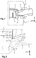
- FIG. 1 and 2 a device forming a step according to the invention, seen respectively from the side and from above.
- This device comprises a bodywork element 1 of a motor vehicle, typically a front bumper of the vehicle.
- This body element 1 comprises a cavity 2 delimited by a bottom wall 3 oriented substantially horizontally forming a bearing surface for an anterior portion of the foot 4 of a user.
- the cavity 2 is further defined by an upper wall 5 and a bottom wall 6 closing the inside of the cavity 2 and providing a junction of the bottom wall 3 and the top wall 5 with an external front surface 7 of the body element 1.
- the bottom wall 6 has a top view in the form of a bowl whose edges are connected to the outer end surface 7, which is typically oriented substantially vertically in the vicinity of the cavity 2. According to FIG.
- the step device comprises a movable plate 8 articulated on a structural element 9 of the vehicle, between a deployed position below the bottom wall 3 towards the bodywork element 1 (visible at figure 1-5 ), and a retracted position opposite the bodywork element 1 (as visible in FIG. figure 6 ).
- the deployed position is located at an advanced position relative to the retracted position, which is located further back towards the rear of the vehicle.
- the displacement of the movable plate 8 towards the retracted position is carried out under the constraint of the bodywork element 1 locally undergoing a deformation following an impact, typically a pedestrian impact in which the leg of a pedestrian 10, schematically represented by a circle to the figure 6 is struck by the bodywork element 1.
- the movable plate 8 is articulated about a substantially vertical axis of rotation Z1 carried by a structural element 9 of the vehicle.
- This structural element 9 is typically constituted by a front zone of a longitudinal member 11 of the vehicle or by an end of a front cross member 12 of the vehicle.
- the front cross member 12 which extends essentially in the direction transverse Y of the vehicle is connected at its lateral ends to the front ends of longitudinal members 11 of the vehicle, the longitudinal members 11 constituting structural elements which are oriented substantially in the longitudinal direction X of the vehicle.
- the axis of rotation Z1 of the movable plate 8 is therefore located on the inside of the vehicle, that is to say on the side of the median longitudinal vertical plane of the vehicle.
- the movable plate 8 is oriented substantially horizontally and is supported by a substantially vertical rear wall 13 connected to the axis of rotation Z1.
- the movable plate 8 and the rear wall 13 are typically made of elements from sheet metal assembled-welded or shaped by folding from a single piece of metal to obtain the general shape of a square. Rigidification conformations (not shown), such as locally deformed zones by stamping may be provided in the folding zone or in other areas of the plate 8 or the rear wall 13.
- the movable plate 8 and the rear wall 13 have a thickness of the order of 2.5 mm.
- the rear wall 13 provides the support function of the movable plate 8 and is connected to the structural element 9 by a hinge shown exploded at the figure 7 .
- the axis of rotation Z1 is materialized by a cylindrical axis whose diameter is of the order of 8 mm by way of non-limiting example. This cylindrical axis passes through the structural element 9 in a median zone of the articulation, considered vertically, as well as the rear wall 13 in the upper and lower zones of the articulation, bordering vertically the structural element 9.
- the movable plate 8 is shaped to withstand a vertical load of 120kg applied in the vertical direction Z.
- return means 14 are arranged on the axis of rotation Z1 and are shaped to return by default the movable plate 8 in the deployed position in the direction of the bodywork element 1.
- "Default” means “naturally” i.e., in the absence of opposite stress applied to the movable plate 8.
- abutment means are provided to limit the displacement of the movable plate 8 in the deployed position. Whatever its angular position about the axis of rotation Z1, the movable plate 8 remains below the bottom wall 3 of the cavity 2, at a distance of between 0.5 and 5 mm, which allows a mounting of the plate mobile 8 on the structural element 9, 11, 12 without conflict with the body member 1 and is sufficient clearance to allow movement of the movable plate 8 without obstacle.
- the movable plate 8 is advanced towards the bodywork element 1 over a length at least equal to half the depth of the cavity 2, measured longitudinally in a central region of the cavity 2, which is aligned with a notional plane P substantially corresponding to the longitudinal median plane of the foot of a person engaging in the cavity 2. This plane is parallel to the longitudinal direction X of the vehicle.
- the movable plate 8 is advanced towards the bodywork element 1 over a length substantially equal to two-thirds of the depth of the cavity 2 measured along the fictional plane P.
- the lower wall 3 When a user engages its foot in the cavity and relies on the lower surface 3 to rise and reach for example the windshield of the vehicle, the lower wall 3 locally deforms down under the force due to the weight of the user, until it comes to cooperate in contact with the movable plate 8 disposed under it in the deployed position.
- the deformation of the lower surface 3 of the cavity 2 is of the order of a few millimeters and corresponds to the functional space formed above the movable plate 8 to allow its mounting and pivoting in case of pedestrian impact.
Description
La présente invention concerne un dispositif formant marchepied comprenant un élément de carrosserie, notamment un bouclier d'un véhicule automobile, une cavité ménagée dans l'élément de carrosserie délimitée par une paroi inférieure formant une surface d'appui pour une partie antérieure du pied d'un utilisateur.The present invention relates to a step device comprising a bodywork element, in particular a shield of a motor vehicle, a cavity formed in the bodywork element delimited by a lower wall forming a bearing surface for an anterior portion of the foot of the body. 'an user.
Un véhicule automobile de type fourgonnette ou utilitaire comprend classiquement des marchepieds disposés de chaque côté, chaque marchepied comportant une cavité ménagée dans le bouclier avant, afin de permettre à un utilisateur de s'élever vers le pare-brise pour enlever le givre ou de la neige accumulée sur celui-ci. Le marchepied doit à cet effet présenter une rigidité suffisante pour supporter le poids d'un utilisateur. D'un autre côté, le bouclier doit également satisfaire la réglementation « ECE127 » applicable au choc piéton, notamment le « choc tibia ». Cette réglementation suppose que le bouclier présente une zone de contact suffisamment molle pour se déformer et absorber localement le choc au contact d'une jambe. Les marchepieds doivent donc satisfaire des besoins antagonistes. Le document
L'invention a pour but de pallier tout ou partie des inconvénients précédents en proposant un dispositif de marchepied satisfaisant autant la fonction de rigidité attendue pour supporter le poids complet d'une personne, que le besoin de souplesse nécessaire du bouclier en cas de choc.The invention aims to overcome all or part of the aforementioned drawbacks by providing a step device satisfying both the rigidity function expected to support the full weight of a person, the need for flexibility of the shield in case of shock.
A cet effet, l'invention a pour objet un dispositif formant marchepied selon la définition de la revendication 1. Selon d'autres caractéristiques avantageuses de l'invention :
- le plateau mobile est articulé autour d'un axe de rotation sensiblement vertical porté par un élément de structure du véhicule, notamment une zone avant d'un longeron du véhicule ou une traverse avant du véhicule,
- le plateau mobile est orienté de façon sensiblement horizontale et est supporté par une paroi arrière sensiblement verticale reliée à l'axe de rotation,
- des moyens de rappel sont disposés sur l'axe de rotation et sont conformés pour ramener le plateau mobile dans la position déployée,
- des moyens de butée sont prévus pour limiter le déplacement du plateau mobile dans la position déployée,
- le plateau mobile est disposé en dessous de la paroi inférieure de la cavité, à une distance comprise entre 0,5 et 5 mm,
- le plateau mobile dans la position déployée est avancé en direction de l'élément de carrosserie sur une longueur au moins égale à la moitié de la profondeur de la cavité, mesurée longitudinalement dans une zone centrale de la cavité,
- the movable plate is articulated around a substantially vertical axis of rotation carried by a structural element of the vehicle, in particular a front zone of a vehicle spar or a front cross member of the vehicle,
- the movable plate is oriented substantially horizontally and is supported by a substantially vertical rear wall connected to the axis of rotation,
- return means are arranged on the axis of rotation and are shaped to return the movable plate in the deployed position,
- stop means are provided to limit the displacement of the movable plate in the deployed position,
- the movable plate is disposed below the lower wall of the cavity, at a distance of between 0.5 and 5 mm,
- the movable plate in the extended position is advanced towards the bodywork element for a length at least equal to half the depth of the cavity, measured longitudinally in a central zone of the cavity,
L'invention sera mieux comprise à la lecture de la description suivante d'un exemple non limitatif de l'invention, et à la lumière des dessins annexés sur lesquels :
- la
figure 1 représente une vue de côté d'un dispositif formant marchepied selon l'invention, - la
figure 2 représente une vue de dessus du dispositif de lafigure 1 , - la
figure 3 est une vue en perspective depuis l'intérieur de l'élément de carrosserie, du dispositif de lafigure 1 , - la
figure 4 est une vue de l'arrière vers l'avant du dispositif formant marchepied de lafigure 1 , - les
figures 5 et 6 sont des vues de dessus du dispositif de lafigure 1 représentant le plateau mobile respectivement dans la position déployée et dans la position escamotée, et - la
figure 7 représente une vue éclatée d'une partie mobile du dispositif formant marchepied de lafigure 1 illustrant le plateau articulé sur son axe de rotation.
- the
figure 1 represents a side view of a device forming a step according to the invention, - the
figure 2 represents a top view of the device of thefigure 1 , - the
figure 3 is a perspective view from the inside of the bodywork element, the device of thefigure 1 , - the
figure 4 is a view from the rear to the front of the device forming the running board of thefigure 1 , - the
Figures 5 and 6 are top views of the device from thefigure 1 representing the movable plate respectively in the deployed position and in the retracted position, and - the
figure 7 is an exploded view of a moving part of the step device of thefigure 1 illustrating the articulated plate on its axis of rotation.
Pour les besoins de la description, les directions et orientations sont indiquées en référence au repère XYZ classiquement utilisé en conception automobile, dans lequel X est la direction longitudinale avant-arrière du véhicule, dirigé vers l'arrière, Y est la direction transversale au véhicule, dirigé vers la droite et Z la direction verticale dirigée vers le haut.
Les notions avant-arrière s'entendent par rapport au sens de marche normal du véhicule qui est dirigé vers l'avant.
Le terme « sensiblement » indique qu'un léger écart est admis par rapport à une position ou disposition nominale déterminée, tout en restant inclus dans le cadre de l'invention. Par exemple « sensiblement vertical » indique qu'un écart de l'ordre de 10° par rapport à une orientation strictement verticale est admis dans le cadre de l'invention.For the purposes of the description, the directions and orientations are indicated with reference to the XYZ mark conventionally used in automotive design, in which X is the longitudinal direction of the front-rear of the vehicle, directed towards the rear, Y is the direction transverse to the vehicle , directed to the right and Z the vertical direction directed upwards.
Front-to-back concepts refer to the direction of normal operation of the vehicle that is directed forward.
The term "substantially" indicates that a slight deviation is allowed with respect to a given nominal position or disposition, while remaining within the scope of the invention. For example "substantially vertical" indicates that a difference of the order of 10 ° relative to a strictly vertical orientation is allowed within the scope of the invention.
On a représenté aux
Le plateau mobile 8 est articulé autour d'un axe de rotation Z1 sensiblement vertical porté par un élément de structure 9 du véhicule. Cet élément de structure 9 est typiquement constitué par une zone avant d'un longeron 11 du véhicule ou par une extrémité d'une traverse avant 12 du véhicule. Comme on le voit aux
Le plateau mobile 8 est orienté de façon sensiblement horizontale et est supporté par une paroi arrière 13 sensiblement verticale reliée à l'axe de rotation Z1.
Le plateau mobile 8 et la paroi arrière 13 sont typiquement constitués d'éléments issus de tôlerie assemblés-soudés ou conformés par pliage à partir d'une unique pièce métallique pour obtenir la forme générale d'une équerre. Des conformations de rigidifications (non représentées), telle que des zones localement déformées par emboutissage peuvent être prévues dans la zone de pliage ou dans d'autres zones du plateau 8 ou de la paroi arrière 13.
A titre d'exemple non limitatif, le plateau mobile 8 et la paroi arrière 13 ont une épaisseur de l'ordre de 2,5 mm.
La paroi arrière 13 assure la fonction de support du plateau mobile 8 et est reliée à l'élément de structure 9 par une articulation représentée en éclaté à la
Le plateau mobile 8 est conformé pour résister à une charge verticale de 120kg appliquée suivant la direction verticale Z.
Selon un aspect de l'invention visible à la
The
The
The
By way of non-limiting example, the
The
The
According to one aspect of the invention visible to the
On note encore que des moyens de butée (non représentés) sont prévus pour limiter le déplacement du plateau mobile 8 dans la position déployée.
Quelle que soit sa position angulaire autour de l'axe de rotation Z1, le plateau mobile 8 demeure en dessous de la paroi inférieure 3 de la cavité 2, à une distance comprise entre 0,5 et 5 mm, qui permet un montage du plateau mobile 8 sur l'élément de structure 9, 11, 12 sans conflit avec l'élément de carrosserie 1 et constitue un jeu suffisant pour permettre un déplacement du plateau mobile 8 sans obstacle.
En référence aux
Whatever its angular position about the axis of rotation Z1, the
With reference to
Bien entendu, l'invention n'est pas limitée aux modes ou variantes de réalisation décrits précédemment et comprends tous les équivalents techniques de ces moyens.Of course, the invention is not limited to the modes or embodiments described above and includes all the technical equivalents of these means.
Claims (8)
- Step-forming device comprising a body element (1) of a motor vehicle, a cavity (2) formed in the body element (1) and delimited by a lower wall (3) forming a bearing surface for a front part of the foot (4) of a user, characterized in that the cavity (2) is additionally delimited by an upper wall (5) and by an end wall (6) closing an interior of the cavity (2), and in that the device comprises a movable plate (8) articulated on a structural element (9, 11, 12) of the vehicle, between a deployed position in which it is deployed below the lower wall (3) in the direction of the body element (1), and a retracted position in which it is retracted away from the body element (1), the movement of the movable plate (8) towards the retracted position being produced under the stress of the body element (1) being subjected to a deformation following an impact.
- Device according to Claim 1, characterized in that the movable plate (8) is articulated about a substantially vertical axis of rotation (Z1) borne by a structural element (9, 11, 12) of the vehicle, in particular a front region of a longitudinal member (11) of the vehicle or a front crossmember (12) of the vehicle.
- Device according to Claim 2, characterized in that the movable plate (8) is oriented substantially horizontally and is supported by a substantially vertical rear wall (13) connected to the axis of rotation (Z1).
- Device according to Claim 2 or 3, characterized in that return means (14) are arranged on the axis of rotation (Z1) and are configured to return the movable plate (8) into the deployed position.
- Device according to Claim 4, characterized in that stop means are provided to limit the movement of the movable plate (8) in the deployed position.
- Device according to any one of Claims 3 to 5, characterized in that the movable plate (8) is arranged below the lower wall (3) of the cavity (2), at a distance of between 0.5 and 5 mm.
- Device according to any one of the preceding claims, characterized in that the movable plate (8) in the deployed position is advanced in the direction of the body element (1) over a length at least equal to half the depth of the cavity (2), measured longitudinally in a central area of the cavity (2).
- Motor vehicle, characterized in that it comprises a device according to any one of the preceding claims.
Applications Claiming Priority (1)
| Application Number | Priority Date | Filing Date | Title |
|---|---|---|---|
| FR1552102A FR3033764B1 (en) | 2015-03-16 | 2015-03-16 | DEVICE FORMING A FOOTBOAT OF A MOTOR VEHICLE |
Publications (2)
| Publication Number | Publication Date |
|---|---|
| EP3069936A1 EP3069936A1 (en) | 2016-09-21 |
| EP3069936B1 true EP3069936B1 (en) | 2017-11-22 |
Family
ID=53366050
Family Applications (1)
| Application Number | Title | Priority Date | Filing Date |
|---|---|---|---|
| EP16305090.9A Active EP3069936B1 (en) | 2015-03-16 | 2016-01-29 | Device forming a step of a motor vehicle |
Country Status (2)
| Country | Link |
|---|---|
| EP (1) | EP3069936B1 (en) |
| FR (1) | FR3033764B1 (en) |
Families Citing this family (1)
| Publication number | Priority date | Publication date | Assignee | Title |
|---|---|---|---|---|
| FR3139787A1 (en) | 2022-09-19 | 2024-03-22 | Renault S.A.S | Device forming a step of a motor vehicle |
Family Cites Families (2)
| Publication number | Priority date | Publication date | Assignee | Title |
|---|---|---|---|---|
| DE3826542A1 (en) * | 1988-08-04 | 1990-02-08 | Man Nutzfahrzeuge Ag | Entry into the driver's cab of a utility vehicle |
| DE29900510U1 (en) * | 1999-01-14 | 1999-08-12 | Haslbeck Technik Gmbh | Support structure for fastening a molded part to a vehicle body |
-
2015
- 2015-03-16 FR FR1552102A patent/FR3033764B1/en not_active Expired - Fee Related
-
2016
- 2016-01-29 EP EP16305090.9A patent/EP3069936B1/en active Active
Non-Patent Citations (1)
| Title |
|---|
| None * |
Also Published As
| Publication number | Publication date |
|---|---|
| FR3033764B1 (en) | 2017-03-03 |
| EP3069936A1 (en) | 2016-09-21 |
| FR3033764A1 (en) | 2016-09-23 |
Similar Documents
| Publication | Publication Date | Title |
|---|---|---|
| FR2780927A1 (en) | DEVICE FOR FIXING THE BODIES OF A BUMPER ON A VEHICLE BODY WING | |
| FR2858798A1 (en) | TECHNICAL FRONT PANEL FRONT OF A MOTOR VEHICLE, TECHNICAL FRONT PANEL AND COOLING MODULE SUPPORT PROVIDED WITH SUCH A TRAVERSE | |
| EP3061696B1 (en) | Blank for forming a packaging of at least one windscreen wiper, packaging and method of producing such a packaging | |
| EP2186686A1 (en) | Shifting device for rigid element and vehicle equipped therewith | |
| FR3047037B1 (en) | FLUSH HANDLE WITH PUSH-PULL FUNCTION FOR OPENING MOTOR VEHICLE | |
| EP3197722B1 (en) | Arrangement of a floor inside a luggage compartment of a motor vehicle comprising retractable seats | |
| EP1901946B1 (en) | Motor vehicle front wing with deformable sealing bulkhead | |
| EP3069936B1 (en) | Device forming a step of a motor vehicle | |
| FR3051728A1 (en) | INTERNAL LINING OF REAR SHUTTER | |
| WO2015189500A1 (en) | Metal insert for a vehicle towing means | |
| FR2987335A1 (en) | MOTOR VEHICLE WATER BOX CAPABLE OF ABSORBING A PART OF THE ENERGY OF A PITCH SHOCK AND CORRESPONDING FRONT STRUCTURE | |
| EP1252045B1 (en) | Device for fixing bumper guards | |
| EP3359422B1 (en) | Drawer integrated in a motor vehicle | |
| EP3969710B1 (en) | Overload bumper for motor vehicle hood | |
| EP3409567B1 (en) | Support device for a dashboard of a motor vehicle | |
| EP3372478B1 (en) | Front panel part of a motor vehicle located in a collosion area integrated a rigid housing | |
| EP3210821B1 (en) | End cap for profile comprising a portion with a u-shaped cross section | |
| WO2021064307A1 (en) | Side impact absorber for a motor vehicle | |
| FR3040677A1 (en) | ARRANGEMENT OF A WHEEL PASSAGE OF A MOTOR VEHICLE | |
| FR3024852A1 (en) | ARRANGEMENT FOR FIXING A TURNING HANDLE OF A MOTOR VEHICLE | |
| EP2616285B1 (en) | Vehicle adapted for absorbing collision with a pedestrian | |
| FR2987011A1 (en) | Shock absorber for fixing on upper front cross beam of car, has horizontal partition extending between two transverse and vertical partitions within zone, which is located at right sides of opposite ends of cross beam | |
| FR2970051A1 (en) | Device for fixing control assembly with flywheel of car, has rods whose ends are solidarized with internal face, so that traction exerted on body causes deformation of end zone and another part to stop co-operation between clipping units | |
| FR2828853A1 (en) | RIGID PLATE FOR COVERING A STEP AND STEP PROVIDED WITH THIS PLATE | |
| FR2970050A1 (en) | Device for fixing body i.e. control assembly, with another body i.e. flywheel, of car, has deformable rod whose end is integral with locking element adapted to translate via opening of part to be housed in housing |
Legal Events
| Date | Code | Title | Description |
|---|---|---|---|
| PUAI | Public reference made under article 153(3) epc to a published international application that has entered the european phase |
Free format text: ORIGINAL CODE: 0009012 |
|
| AK | Designated contracting states |
Kind code of ref document: A1 Designated state(s): AL AT BE BG CH CY CZ DE DK EE ES FI FR GB GR HR HU IE IS IT LI LT LU LV MC MK MT NL NO PL PT RO RS SE SI SK SM TR |
|
| AX | Request for extension of the european patent |
Extension state: BA ME |
|
| 17P | Request for examination filed |
Effective date: 20161220 |
|
| RBV | Designated contracting states (corrected) |
Designated state(s): AL AT BE BG CH CY CZ DE DK EE ES FI FR GB GR HR HU IE IS IT LI LT LU LV MC MK MT NL NO PL PT RO RS SE SI SK SM TR |
|
| GRAP | Despatch of communication of intention to grant a patent |
Free format text: ORIGINAL CODE: EPIDOSNIGR1 |
|
| RIC1 | Information provided on ipc code assigned before grant |
Ipc: B60R 19/48 20060101ALI20170519BHEP Ipc: B60R 3/00 20060101AFI20170519BHEP |
|
| INTG | Intention to grant announced |
Effective date: 20170620 |
|
| GRAS | Grant fee paid |
Free format text: ORIGINAL CODE: EPIDOSNIGR3 |
|
| GRAA | (expected) grant |
Free format text: ORIGINAL CODE: 0009210 |
|
| AK | Designated contracting states |
Kind code of ref document: B1 Designated state(s): AL AT BE BG CH CY CZ DE DK EE ES FI FR GB GR HR HU IE IS IT LI LT LU LV MC MK MT NL NO PL PT RO RS SE SI SK SM TR |
|
| REG | Reference to a national code |
Ref country code: GB Ref legal event code: FG4D Free format text: NOT ENGLISH |
|
| REG | Reference to a national code |
Ref country code: CH Ref legal event code: EP |
|
| REG | Reference to a national code |
Ref country code: IE Ref legal event code: FG4D Free format text: LANGUAGE OF EP DOCUMENT: FRENCH |
|
| REG | Reference to a national code |
Ref country code: AT Ref legal event code: REF Ref document number: 948086 Country of ref document: AT Kind code of ref document: T Effective date: 20171215 |
|
| REG | Reference to a national code |
Ref country code: DE Ref legal event code: R096 Ref document number: 602016000889 Country of ref document: DE |
|
| REG | Reference to a national code |
Ref country code: FR Ref legal event code: PLFP Year of fee payment: 3 |
|
| REG | Reference to a national code |
Ref country code: NL Ref legal event code: MP Effective date: 20171122 |
|
| REG | Reference to a national code |
Ref country code: LT Ref legal event code: MG4D |
|
| REG | Reference to a national code |
Ref country code: AT Ref legal event code: MK05 Ref document number: 948086 Country of ref document: AT Kind code of ref document: T Effective date: 20171122 |
|
| PG25 | Lapsed in a contracting state [announced via postgrant information from national office to epo] |
Ref country code: FI Free format text: LAPSE BECAUSE OF FAILURE TO SUBMIT A TRANSLATION OF THE DESCRIPTION OR TO PAY THE FEE WITHIN THE PRESCRIBED TIME-LIMIT Effective date: 20171122 Ref country code: NL Free format text: LAPSE BECAUSE OF FAILURE TO SUBMIT A TRANSLATION OF THE DESCRIPTION OR TO PAY THE FEE WITHIN THE PRESCRIBED TIME-LIMIT Effective date: 20171122 Ref country code: NO Free format text: LAPSE BECAUSE OF FAILURE TO SUBMIT A TRANSLATION OF THE DESCRIPTION OR TO PAY THE FEE WITHIN THE PRESCRIBED TIME-LIMIT Effective date: 20180222 Ref country code: SE Free format text: LAPSE BECAUSE OF FAILURE TO SUBMIT A TRANSLATION OF THE DESCRIPTION OR TO PAY THE FEE WITHIN THE PRESCRIBED TIME-LIMIT Effective date: 20171122 Ref country code: ES Free format text: LAPSE BECAUSE OF FAILURE TO SUBMIT A TRANSLATION OF THE DESCRIPTION OR TO PAY THE FEE WITHIN THE PRESCRIBED TIME-LIMIT Effective date: 20171122 Ref country code: LT Free format text: LAPSE BECAUSE OF FAILURE TO SUBMIT A TRANSLATION OF THE DESCRIPTION OR TO PAY THE FEE WITHIN THE PRESCRIBED TIME-LIMIT Effective date: 20171122 |
|
| PG25 | Lapsed in a contracting state [announced via postgrant information from national office to epo] |
Ref country code: LV Free format text: LAPSE BECAUSE OF FAILURE TO SUBMIT A TRANSLATION OF THE DESCRIPTION OR TO PAY THE FEE WITHIN THE PRESCRIBED TIME-LIMIT Effective date: 20171122 Ref country code: AT Free format text: LAPSE BECAUSE OF FAILURE TO SUBMIT A TRANSLATION OF THE DESCRIPTION OR TO PAY THE FEE WITHIN THE PRESCRIBED TIME-LIMIT Effective date: 20171122 Ref country code: GR Free format text: LAPSE BECAUSE OF FAILURE TO SUBMIT A TRANSLATION OF THE DESCRIPTION OR TO PAY THE FEE WITHIN THE PRESCRIBED TIME-LIMIT Effective date: 20180223 Ref country code: BG Free format text: LAPSE BECAUSE OF FAILURE TO SUBMIT A TRANSLATION OF THE DESCRIPTION OR TO PAY THE FEE WITHIN THE PRESCRIBED TIME-LIMIT Effective date: 20180222 Ref country code: HR Free format text: LAPSE BECAUSE OF FAILURE TO SUBMIT A TRANSLATION OF THE DESCRIPTION OR TO PAY THE FEE WITHIN THE PRESCRIBED TIME-LIMIT Effective date: 20171122 Ref country code: RS Free format text: LAPSE BECAUSE OF FAILURE TO SUBMIT A TRANSLATION OF THE DESCRIPTION OR TO PAY THE FEE WITHIN THE PRESCRIBED TIME-LIMIT Effective date: 20171122 |
|
| PG25 | Lapsed in a contracting state [announced via postgrant information from national office to epo] |
Ref country code: CZ Free format text: LAPSE BECAUSE OF FAILURE TO SUBMIT A TRANSLATION OF THE DESCRIPTION OR TO PAY THE FEE WITHIN THE PRESCRIBED TIME-LIMIT Effective date: 20171122 Ref country code: CY Free format text: LAPSE BECAUSE OF FAILURE TO SUBMIT A TRANSLATION OF THE DESCRIPTION OR TO PAY THE FEE WITHIN THE PRESCRIBED TIME-LIMIT Effective date: 20171122 Ref country code: DK Free format text: LAPSE BECAUSE OF FAILURE TO SUBMIT A TRANSLATION OF THE DESCRIPTION OR TO PAY THE FEE WITHIN THE PRESCRIBED TIME-LIMIT Effective date: 20171122 Ref country code: EE Free format text: LAPSE BECAUSE OF FAILURE TO SUBMIT A TRANSLATION OF THE DESCRIPTION OR TO PAY THE FEE WITHIN THE PRESCRIBED TIME-LIMIT Effective date: 20171122 Ref country code: SK Free format text: LAPSE BECAUSE OF FAILURE TO SUBMIT A TRANSLATION OF THE DESCRIPTION OR TO PAY THE FEE WITHIN THE PRESCRIBED TIME-LIMIT Effective date: 20171122 |
|
| REG | Reference to a national code |
Ref country code: DE Ref legal event code: R097 Ref document number: 602016000889 Country of ref document: DE |
|
| PG25 | Lapsed in a contracting state [announced via postgrant information from national office to epo] |
Ref country code: SM Free format text: LAPSE BECAUSE OF FAILURE TO SUBMIT A TRANSLATION OF THE DESCRIPTION OR TO PAY THE FEE WITHIN THE PRESCRIBED TIME-LIMIT Effective date: 20171122 Ref country code: RO Free format text: LAPSE BECAUSE OF FAILURE TO SUBMIT A TRANSLATION OF THE DESCRIPTION OR TO PAY THE FEE WITHIN THE PRESCRIBED TIME-LIMIT Effective date: 20171122 Ref country code: PL Free format text: LAPSE BECAUSE OF FAILURE TO SUBMIT A TRANSLATION OF THE DESCRIPTION OR TO PAY THE FEE WITHIN THE PRESCRIBED TIME-LIMIT Effective date: 20171122 |
|
| PG25 | Lapsed in a contracting state [announced via postgrant information from national office to epo] |
Ref country code: MT Free format text: LAPSE BECAUSE OF FAILURE TO SUBMIT A TRANSLATION OF THE DESCRIPTION OR TO PAY THE FEE WITHIN THE PRESCRIBED TIME-LIMIT Effective date: 20171122 |
|
| PLBE | No opposition filed within time limit |
Free format text: ORIGINAL CODE: 0009261 |
|
| STAA | Information on the status of an ep patent application or granted ep patent |
Free format text: STATUS: NO OPPOSITION FILED WITHIN TIME LIMIT |
|
| 26N | No opposition filed |
Effective date: 20180823 |
|
| PG25 | Lapsed in a contracting state [announced via postgrant information from national office to epo] |
Ref country code: LU Free format text: LAPSE BECAUSE OF NON-PAYMENT OF DUE FEES Effective date: 20180129 |
|
| REG | Reference to a national code |
Ref country code: IE Ref legal event code: MM4A |
|
| REG | Reference to a national code |
Ref country code: BE Ref legal event code: MM Effective date: 20180131 |
|
| PG25 | Lapsed in a contracting state [announced via postgrant information from national office to epo] |
Ref country code: BE Free format text: LAPSE BECAUSE OF NON-PAYMENT OF DUE FEES Effective date: 20180131 Ref country code: SI Free format text: LAPSE BECAUSE OF FAILURE TO SUBMIT A TRANSLATION OF THE DESCRIPTION OR TO PAY THE FEE WITHIN THE PRESCRIBED TIME-LIMIT Effective date: 20171122 |
|
| PG25 | Lapsed in a contracting state [announced via postgrant information from national office to epo] |
Ref country code: IE Free format text: LAPSE BECAUSE OF NON-PAYMENT OF DUE FEES Effective date: 20180129 |
|
| PG25 | Lapsed in a contracting state [announced via postgrant information from national office to epo] |
Ref country code: MC Free format text: LAPSE BECAUSE OF FAILURE TO SUBMIT A TRANSLATION OF THE DESCRIPTION OR TO PAY THE FEE WITHIN THE PRESCRIBED TIME-LIMIT Effective date: 20171122 |
|
| REG | Reference to a national code |
Ref country code: CH Ref legal event code: PL |
|
| PG25 | Lapsed in a contracting state [announced via postgrant information from national office to epo] |
Ref country code: LI Free format text: LAPSE BECAUSE OF NON-PAYMENT OF DUE FEES Effective date: 20190131 Ref country code: CH Free format text: LAPSE BECAUSE OF NON-PAYMENT OF DUE FEES Effective date: 20190131 |
|
| PG25 | Lapsed in a contracting state [announced via postgrant information from national office to epo] |
Ref country code: TR Free format text: LAPSE BECAUSE OF FAILURE TO SUBMIT A TRANSLATION OF THE DESCRIPTION OR TO PAY THE FEE WITHIN THE PRESCRIBED TIME-LIMIT Effective date: 20171122 |
|
| PG25 | Lapsed in a contracting state [announced via postgrant information from national office to epo] |
Ref country code: PT Free format text: LAPSE BECAUSE OF FAILURE TO SUBMIT A TRANSLATION OF THE DESCRIPTION OR TO PAY THE FEE WITHIN THE PRESCRIBED TIME-LIMIT Effective date: 20171122 |
|
| PG25 | Lapsed in a contracting state [announced via postgrant information from national office to epo] |
Ref country code: MK Free format text: LAPSE BECAUSE OF NON-PAYMENT OF DUE FEES Effective date: 20171122 Ref country code: HU Free format text: LAPSE BECAUSE OF FAILURE TO SUBMIT A TRANSLATION OF THE DESCRIPTION OR TO PAY THE FEE WITHIN THE PRESCRIBED TIME-LIMIT; INVALID AB INITIO Effective date: 20160129 |
|
| PG25 | Lapsed in a contracting state [announced via postgrant information from national office to epo] |
Ref country code: AL Free format text: LAPSE BECAUSE OF FAILURE TO SUBMIT A TRANSLATION OF THE DESCRIPTION OR TO PAY THE FEE WITHIN THE PRESCRIBED TIME-LIMIT Effective date: 20171122 Ref country code: IS Free format text: LAPSE BECAUSE OF FAILURE TO SUBMIT A TRANSLATION OF THE DESCRIPTION OR TO PAY THE FEE WITHIN THE PRESCRIBED TIME-LIMIT Effective date: 20180322 |
|
| PGFP | Annual fee paid to national office [announced via postgrant information from national office to epo] |
Ref country code: FR Payment date: 20230124 Year of fee payment: 8 |
|
| PGFP | Annual fee paid to national office [announced via postgrant information from national office to epo] |
Ref country code: IT Payment date: 20230120 Year of fee payment: 8 Ref country code: GB Payment date: 20230119 Year of fee payment: 8 Ref country code: DE Payment date: 20230123 Year of fee payment: 8 |
|
| P01 | Opt-out of the competence of the unified patent court (upc) registered |
Effective date: 20230608 |