EP2939835B1 - Printing apparatus and printing method - Google Patents
Printing apparatus and printing method Download PDFInfo
- Publication number
- EP2939835B1 EP2939835B1 EP15160824.7A EP15160824A EP2939835B1 EP 2939835 B1 EP2939835 B1 EP 2939835B1 EP 15160824 A EP15160824 A EP 15160824A EP 2939835 B1 EP2939835 B1 EP 2939835B1
- Authority
- EP
- European Patent Office
- Prior art keywords
- printing
- unit
- label
- time
- Prior art date
- Legal status (The legal status is an assumption and is not a legal conclusion. Google has not performed a legal analysis and makes no representation as to the accuracy of the status listed.)
- Active
Links
- 238000007639 printing Methods 0.000 title claims description 99
- 238000000034 method Methods 0.000 title claims description 35
- 239000007788 liquid Substances 0.000 claims description 17
- 238000005259 measurement Methods 0.000 claims description 16
- 238000002360 preparation method Methods 0.000 claims description 10
- 238000012805 post-processing Methods 0.000 claims description 8
- 238000001514 detection method Methods 0.000 claims description 3
- 230000007246 mechanism Effects 0.000 description 23
- 238000010586 diagram Methods 0.000 description 12
- 230000008569 process Effects 0.000 description 6
- 230000009467 reduction Effects 0.000 description 6
- 238000007711 solidification Methods 0.000 description 6
- 230000008023 solidification Effects 0.000 description 6
- 230000008719 thickening Effects 0.000 description 6
- 238000005520 cutting process Methods 0.000 description 4
- 238000012545 processing Methods 0.000 description 4
- 238000006243 chemical reaction Methods 0.000 description 3
- 238000011144 upstream manufacturing Methods 0.000 description 3
- 230000006870 function Effects 0.000 description 2
- 239000002904 solvent Substances 0.000 description 2
- 230000005540 biological transmission Effects 0.000 description 1
- 230000005587 bubbling Effects 0.000 description 1
- 238000004140 cleaning Methods 0.000 description 1
- 230000006866 deterioration Effects 0.000 description 1
- 238000007599 discharging Methods 0.000 description 1
- 230000008020 evaporation Effects 0.000 description 1
- 238000001704 evaporation Methods 0.000 description 1
- 238000007641 inkjet printing Methods 0.000 description 1
- 239000000463 material Substances 0.000 description 1
- 230000002093 peripheral effect Effects 0.000 description 1
- 238000005070 sampling Methods 0.000 description 1
- 238000004904 shortening Methods 0.000 description 1
- 238000002834 transmittance Methods 0.000 description 1
Images


Classifications
-
- B—PERFORMING OPERATIONS; TRANSPORTING
- B41—PRINTING; LINING MACHINES; TYPEWRITERS; STAMPS
- B41J—TYPEWRITERS; SELECTIVE PRINTING MECHANISMS, i.e. MECHANISMS PRINTING OTHERWISE THAN FROM A FORME; CORRECTION OF TYPOGRAPHICAL ERRORS
- B41J11/00—Devices or arrangements of selective printing mechanisms, e.g. ink-jet printers or thermal printers, for supporting or handling copy material in sheet or web form
- B41J11/0015—Devices or arrangements of selective printing mechanisms, e.g. ink-jet printers or thermal printers, for supporting or handling copy material in sheet or web form for treating before, during or after printing or for uniform coating or laminating the copy material before or after printing
-
- B—PERFORMING OPERATIONS; TRANSPORTING
- B41—PRINTING; LINING MACHINES; TYPEWRITERS; STAMPS
- B41J—TYPEWRITERS; SELECTIVE PRINTING MECHANISMS, i.e. MECHANISMS PRINTING OTHERWISE THAN FROM A FORME; CORRECTION OF TYPOGRAPHICAL ERRORS
- B41J2/00—Typewriters or selective printing mechanisms characterised by the printing or marking process for which they are designed
- B41J2/005—Typewriters or selective printing mechanisms characterised by the printing or marking process for which they are designed characterised by bringing liquid or particles selectively into contact with a printing material
- B41J2/01—Ink jet
- B41J2/135—Nozzles
- B41J2/165—Prevention or detection of nozzle clogging, e.g. cleaning, capping or moistening for nozzles
- B41J2/16505—Caps, spittoons or covers for cleaning or preventing drying out
- B41J2/16508—Caps, spittoons or covers for cleaning or preventing drying out connected with the printer frame
- B41J2/16511—Constructions for cap positioning
-
- B—PERFORMING OPERATIONS; TRANSPORTING
- B41—PRINTING; LINING MACHINES; TYPEWRITERS; STAMPS
- B41J—TYPEWRITERS; SELECTIVE PRINTING MECHANISMS, i.e. MECHANISMS PRINTING OTHERWISE THAN FROM A FORME; CORRECTION OF TYPOGRAPHICAL ERRORS
- B41J2/00—Typewriters or selective printing mechanisms characterised by the printing or marking process for which they are designed
- B41J2/005—Typewriters or selective printing mechanisms characterised by the printing or marking process for which they are designed characterised by bringing liquid or particles selectively into contact with a printing material
- B41J2/01—Ink jet
- B41J2/135—Nozzles
- B41J2/165—Prevention or detection of nozzle clogging, e.g. cleaning, capping or moistening for nozzles
- B41J2/16585—Prevention or detection of nozzle clogging, e.g. cleaning, capping or moistening for nozzles for paper-width or non-reciprocating print heads
-
- B—PERFORMING OPERATIONS; TRANSPORTING
- B41—PRINTING; LINING MACHINES; TYPEWRITERS; STAMPS
- B41J—TYPEWRITERS; SELECTIVE PRINTING MECHANISMS, i.e. MECHANISMS PRINTING OTHERWISE THAN FROM A FORME; CORRECTION OF TYPOGRAPHICAL ERRORS
- B41J3/00—Typewriters or selective printing or marking mechanisms characterised by the purpose for which they are constructed
- B41J3/407—Typewriters or selective printing or marking mechanisms characterised by the purpose for which they are constructed for marking on special material
- B41J3/4075—Tape printers; Label printers
-
- B—PERFORMING OPERATIONS; TRANSPORTING
- B41—PRINTING; LINING MACHINES; TYPEWRITERS; STAMPS
- B41J—TYPEWRITERS; SELECTIVE PRINTING MECHANISMS, i.e. MECHANISMS PRINTING OTHERWISE THAN FROM A FORME; CORRECTION OF TYPOGRAPHICAL ERRORS
- B41J2/00—Typewriters or selective printing mechanisms characterised by the printing or marking process for which they are designed
- B41J2/005—Typewriters or selective printing mechanisms characterised by the printing or marking process for which they are designed characterised by bringing liquid or particles selectively into contact with a printing material
- B41J2/01—Ink jet
- B41J2/135—Nozzles
- B41J2/165—Prevention or detection of nozzle clogging, e.g. cleaning, capping or moistening for nozzles
- B41J2/16517—Cleaning of print head nozzles
- B41J2002/16573—Cleaning process logic, e.g. for determining type or order of cleaning processes
-
- B—PERFORMING OPERATIONS; TRANSPORTING
- B41—PRINTING; LINING MACHINES; TYPEWRITERS; STAMPS
- B41J—TYPEWRITERS; SELECTIVE PRINTING MECHANISMS, i.e. MECHANISMS PRINTING OTHERWISE THAN FROM A FORME; CORRECTION OF TYPOGRAPHICAL ERRORS
- B41J2/00—Typewriters or selective printing mechanisms characterised by the printing or marking process for which they are designed
- B41J2/005—Typewriters or selective printing mechanisms characterised by the printing or marking process for which they are designed characterised by bringing liquid or particles selectively into contact with a printing material
- B41J2/01—Ink jet
- B41J2/135—Nozzles
- B41J2/165—Prevention or detection of nozzle clogging, e.g. cleaning, capping or moistening for nozzles
- B41J2/16585—Prevention or detection of nozzle clogging, e.g. cleaning, capping or moistening for nozzles for paper-width or non-reciprocating print heads
- B41J2002/16591—Prevention or detection of nozzle clogging, e.g. cleaning, capping or moistening for nozzles for paper-width or non-reciprocating print heads for line print heads above an endless belt
Definitions
- the present invention relates to a printing apparatus and printing method that print on a print medium using a print head capable of ejecting print liquid toward the print medium.
- a printing apparatus that performs printing by ejecting print liquid containing color material from ejection ports arrayed in a print head
- keeping liquid ejection performance of the ejection ports in an adequate state is important for keeping the quality of a printed image good.
- capping that after the completion of a print operation, covers a surface where ejection ports of a print head are formed (ejection port surface) with a capping member is performed. The capping makes it possible to reduce damage to the ejection port surface and thickening/solidification of print liquid associated with the evaporation of a solvent in the print liquid to keep ejection performance of the ejection ports.
- Japanese Patent Laid-Open No. H08-323987(1996) discloses a printing apparatus that uses a print head to print on the plurality of labels affixed on a long mount. Also, among current printing apparatuses, there is one in which on the downstream side of a print head, a post-processing part that performs a predetermined process on a printed print medium or the like is arranged. For example, among printing apparatuses that use a print head to print on labels, there is known one that includes a post-processing part that performs a peeling process to peel off a printed label from a mount or performs a cutting process of each label.
- document US 2014/028771 A1 discloses an ink-jet printing apparatus and a method for printing seamless cans by ejecting print liquid from a printing unit comprising ejection ports for ejecting the print liquid
- document US 2012/236061 A1 discloses a method of controlling a printer that cuts recording paper according to a paper cut command after printing print data received from a host computer on the recording paper.
- the present invention in its first aspect provides a printing apparatus as specified in claims 1 to 9.
- the present invention in its second aspect provides a printing method as specified in claim 10.
- FIG. 1 is an explanatory diagram illustrating a schematic configuration of a printing system that includes a printing apparatus 100 in the present embodiment and a host computer (host device) 10 connected to the printing apparatus 100.
- the host computer 10 outputs print data to be printed by the printing apparatus 100, information on a cutting position or a print medium, or the like to the printing apparatus 100 as a control command through a printer cable 11.
- the printing apparatus 100 in the present embodiment uses a continuous sheet wound in a roll shape as a print medium 103.
- the print medium 103 configured to include: a belt-like-shaped long mount 103A and a plurality of labels 103B affixed on the mount 103A in a peelable manner along the longer direction.
- the roll-shaped print medium 103 is held by a medium supply part 102 provided in the printing apparatus 100, and conveyed in a conveyance direction (Y direction) by below-described conveyance unit.
- the conveyance unit in the present embodiment is adapted to be able to convey the print medium 103 not only in a forward conveyance direction (Y1 direction) but also in a backward conveyance direction (Y2 direction) that is a direction opposite to the forward conveyance direction.
- the print medium 103 conveyed in the forward conveyance direction (Y1 direction) from the print medium supply part 102 is given print liquid by a printing part 110 and printed with an image, and then a part of a printed label 103B is peeled off from the mount 103A by a peeling part 112.
- a conveyance motor 105 In a conveyance unit 104 included in the print medium conveyance unit, a conveyance motor 105, conveyance belt 106, and suction fan 107 are provided.
- the conveyance belt 106 is built between guide rollers 108A, 108B, and 108C and a driving roller 108D. Driving force of the conveyance motor 105 rotates the driving roller 108D, and thereby the conveyance belt 106 moves in the forward conveyance direction (Y1 direction) or in the backward conveyance direction (Y2 direction).
- the suction fan 107 is rotated by a motor outside the diagram, and sucks air from a plurality of suction holes (not illustrated) formed in the conveyance belt 106 as well as discharging the sucked air from a discharge port 109 as a discharge part of the conveyance unit 104.
- the print medium 103 is sucked to the surface (surface facing the printing part 110) of the conveyance belt 106 by the suction of air from the suction holes. In doing so, the conveyance belt 106 moves in the forward direction or in the backward direction together with the conveyance belt 106.
- an inkjet type print head 120 as a printing unit is detachably equipped in a position facing a traveling path of the conveyance belt 106.
- the plurality of ejection ports capable of ejecting print liquid (hereinafter also referred to as ink) toward the print medium conveyed by the conveyance belt 106 are formed.
- Each of the ejection ports is supplied with the ink from a common liquid chamber of the print head 120, and the ink is ejected from the ejection port by driving an ejection energy generating element arranged inside the ejection port.
- a surface 120a of the print head 120 where the ejection ports are formed is referred to as an ejection port surface.
- an element such as an electrothermal conversion element (heater) or an electromechanical conversion element (piezo element) is known.
- the electrothermal conversion element generates heat upon receipt of electric energy, bubbles ink inside an ejection port by the heat, and ejects the ink from the ejection port by utilizing a variation in pressure caused by the bubbling.
- the plurality of ejection ports are arranged along a direction intersecting with (in the present embodiment, a direction (X direction) orthogonal to) the conveyance direction (Y direction), and the ejection ports form at least one ejection port array.
- the print head 120 in the present embodiment is a full line type print head, in which the ejection port array having length corresponding to the width of the print medium 103 used is formed.
- the ejection ports of the print head 120 are in an open state of being exposed to the air. At this time, in a situation where ink droplets are ejected from the ejection ports within a certain period of time by the print operation or the like, the ink inside the ejection ports are frequently refreshed to keep the ink in a state suitable for ejection.
- a solvent of the print liquid inside the print head 120 may be evaporated from the ejection ports in the open state, and thickening, solidification, or the like of the print liquid may occur to reduce ejection performance of the ejection ports.
- a capping mechanism as an open/close mechanism that can selectively perform a closing or opening operation of the ejection port surface 102a is provided.
- the capping mechanism 130 in the present embodiment includes: a head moving mechanism 140 adapted to move the print head 120 in a vertical direction (Z direction) ; and a cap moving mechanism 150 adapted to move a capping member 151 capable of covering the ejection port surface of the print head 120.
- the head moving mechanism 140 includes: a rack 141 that is provided on a lateral surface of the printing part 110 including the print head 120; a pinion gear 142 that gears with the rack 141; and a head motor 143 that rotates the pinion gear 142.
- the print head 120 is moved in the vertical direction (Z direction) together with the printing part 110 provided with the rack 141.
- the cap moving mechanism 150 includes: the capping member 151; a rack 152 that is included in part of the capping member 151; a pinion gear 153 that gears with the rack 152; and a cap motor 154 that rotates the pinion gear 153.
- the capping member 151 is moved along a direction (in the present embodiment, the Y direction) intersecting with the Z direction together with the rack 152 gearing with the pinion gear 153.
- FIG. 1 illustrates a state where printing is performed on the print medium 103 by the print head 120a, i.e., a state where the capping member 151 is held in a position (withdrawal position) to open the ejection port surface 120a.
- the print head 120 is moved above the capping member 151 by driving the head motor 143.
- the capping member 151 is moved in the Y1 direction and made to face the ejection port surface 120a through a predetermined gap. Subsequently, the print head 120 is moved downward by driving the head motor 143, and brought into contact with the capping member 151. In doing so, the ejection port surface 120a is closed by the capping member 151, and communicative connection with the air is blocked.
- the ejection port surface 120a can be switched from the close state to the open state.
- the switching operation from the close state to the open state is hereinafter referred to as the opening operation.
- the print head 120 in an opening completion state where the opening operation is completed, the print head 120 is in a state of being able to print on the label 103B conveyed to a print position.
- the opening completion state refers to a state where the print head 120 can print on the label 103B.
- the printing apparatus 100 includes a fore end detecting sensor 111 adapted to detect a fore end position of each label of the print medium in order to determine print timing for the print medium 103.
- the fore end detecting sensor 111 detects the fore end of each of the plurality of labels 103B, which are affixed on the mount 103A of the print sheet 103 conveyed in the forward conveyance direction (Y1 direction), at an upstream position of the position to print the label 130B by the print head 120 in the Y1 direction.
- the fore end detecting sensor 111 includes any or both of a reflection type sensor and a transmission type sensor, and on the basis of the difference in transmittance between the mount and a label, can detect the fore end by detecting a received light amount.
- the fore end detecting sensor 111 can also detect the fore end of the print medium by detecting a received light amount.
- a rotary shaft of the guide roller 108A provided in the conveyance unit 104 is provided with a well-known rotary encoder that rotates in synchronization with the rotary shaft, and the rotary encoder functions as a conveyance position detecting unit adapted to detect a conveyance position of the print medium 103 together with the fore end detecting sensor 111.
- the peeling part 112 for peeling off a printed label 103B printed in the printing part 110 from the mount 103A is provided.
- the peeling part is a post-processing part in the present invention, where a predetermined post-process is performed.
- the peeling part 112 positions the printed label 103B in a peeling position to peel off the printed label 103B from the mount 103A by in different directions, guiding the printed label 103B and the mount 103A of the print medium 103 conveyed in the forward conveyance direction (Y1 direction) by the conveyance unit 104.
- a label detecting sensor 113 detects that the peeled label 103B has been taken out of the peeling part 112 by an operator.
- the conveyance unit 104 conveys the continuous sheet 103 to a print start position in the backward conveyance direction (Y2 direction) opposite to the forward conveyance direction (Y1 direction), and then printing is performed on a next print target label (e.g., a label positioned closest to the label taken out).
- the print start position refers to a position determined such that the fore end of a print target label is positioned on the upstream side of the fore end detecting sensor 111 in the Y1 direction.
- a detecting target label is a label next to the label taken out.
- another label positioned further upstream side of the label next to the label taken out may serve as a print target.
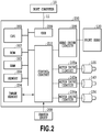
- FIG. 2 is a block diagram illustrating a schematic configuration of a control system 200 of the printing apparatus 100 in the present embodiment.
- the control system 200 includes a central processing unit (CPU) 201 as a control part.
- the CPU 201 executes a control program stored in a nonvolatile memory (ROM) 202 and functions as the control part adapted to control respective peripheral devices.
- the CPU 201 is connected to an RAM 203 used as a work area for various types of data processing and a receive buffer, and an image memory 204 as a development part adapted to develop print data on an image to be printed.
- the CPU 201 is also connected to a memory 206 that stores the below-described acquisition time T, the below-described estimated time Tc, and the like.
- the CPU 201 is connected with a head drive circuit 205 that drives the print head 120, and motor drive circuits corresponding to various types of motors provided in the printing apparatus 100.
- FIG. 2 illustrates motor drive circuits 105a, 143a, and 154a respectively for the above-described conveyance motor 105, head motor 143, and cap motor 154; however, the CPU 201 also controls the other motor drive circuits for motors provided in the printing apparatus 100.
- the motors various types of motors that produce driving force for performing a cleaning operation of the printing apparatus print head, print operation, cutting operation for a print medium, and other operations are provided, and the motor drive circuits for the respective motors are also controlled by the CPU 201.
- the CPU 201 is connected with a sensor group 208 that detects the print medium 103, and operation states of respective parts inside the apparatus.
- the sensor group 208 also includes sensors such as the above-described fore end detecting sensor 111, label detecting sensor 113, and the rotary encoder.
- FIG. 3 is a diagram illustrating various types of commands transmitted in the printing system of the present embodiment.
- the various types of commands illustrated here are transmitted from the host computer 10 to the printing apparatus 100 through the printer cable 11 in the present embodiment.
- 300 represents the print commands.
- the print commands 300 includes commands such as: a print medium setting command 301 that notifies pieces of information on a print medium, such as a type and size; a format command 302 that specifies pieces of information such as a print area; a data command 303 that notifies information of print data on a print image; and a job start command 304.
- the printing apparatus 100 performs a print operation on the basis of the print commands 300 transmitted from the host computer 10.
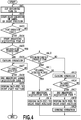
- FIG. 4 is a flowchart illustrating an overall control operation in the present embodiment.
- a determination process and a control process illustrated in FIG. 4 are performed by the CPU 201.
- the CPU 201 sets an estimated elapsed time from when a print operation on a label 103B is ended in the printing part 110 to when the printed label 103B is peeled off from the mount 103A in the peeling part 112 and taken out by an operator.
- the elapsed time set by the estimation setting is defined as an estimated time Tc.
- a method for setting the estimated time Tc will be described later on the basis of FIG. 5 .
- the CPU 201 makes the capping member 151 perform the opening operation, whereas in the case where the ejection port surface 120a is opened, while keeping the open state and conveying the print medium 103 in the forward conveyance direction (Y1 direction) by the conveyance unit 104 to thereby convey a label positioned in the print start position to the print position, the CPU 201 makes the printing part 110 eject the ink toward the label 103B conveyed to the print position and starts image printing.
- the CPU 201 determines whether or not the print medium 103 has been conveyed to a print end position where the print operation on the label 103B is ended.
- the CPU 201 starts measuring an acquisition time T that is an elapsed time from when the print operation on the label 103B in the print position is ended to when the printed label 103B is peeled off from the mount 103A in the peeling part 112, and taken out of the apparatus by the operator.
- the acquisition time T refers to a measured time obtained by actually measuring the elapsed time from when the print operation on the label is ended to when the label is taken out of the apparatus.
- the CPU 201 determines whether or not print data to be printed next is present (whether or not the RAM 203 has print data to be printed next) .
- the CPU 201 determines on the basis of a detection signal from the label detecting sensor 113 whether or not the label 103B sent to the peeling part 112 and peeled off from the mount 103A is taken out by the operator to bring the mount 103A into a non-label state.
- the CPU 201 determines that the mount 103A is in the non-label state (YES in S407), the CPU 201 ends in S408 the above-described measurement operation of the label acquisition time T started in S404, sets the elapsed time from the start of the measurement to the end of the measurement as the acquisition time T, and stores the acquisition time T in the memory 206 relating the acquisition time T to which ordinal number the print operation in S402 (last performed print operation) corresponds to.
- the CPU 201 conveys the print medium 103 in the backward conveyance direction (Y2 direction) to move a label 103B to be printed next to the above-described print start position, and waits to receive next print data.
- the flow proceeds to S410 without performing the closing operation in S408.
- the CPU 201 determines whether or not the above-described estimated time Tc (estimated time Tc that is stored in the memory 206 and corresponds to the print operation in S402 (last performed print operation)) is equal to or less than the below-described openable time T1. In the case where the estimated time Tc is equal to or less than the openable time T1, the CPU 201 waits for the label 103B peeled off in the peeling part 112 to be taken out by the operator while keeping the ejection ports of the print head 120 in the open state.
- the openable time is a time obtained by subtracting a time necessary for the above-described closing operation and a time corresponding to a predetermined margin from the maximum value (maximum open time) of a time for which the ejection port surface 120a can be continuously opened without reducing print quality by the print head 120.
- the openable time may be one obtained without subtracting the time corresponding to the predetermined margin.
- the CPU 201 determines whether or not an elapsed time from when the print operation on the label 103B is ended to when the label detecting sensor 113 detects "no label” is equal to or less than the openable time (T1). In the case where the label detecting sensor 113 detects "no label” within the openable time T1, the CPU 201 ends the above-described measurement of the acquisition time T started in S404, then sets the elapsed time from the start of the measurement to the end of the measurement as the acquisition time T, and stores the acquisition time T in the memory 206 relating the acquisition time to which ordinal number the print operation in S402 (last performed print operation) corresponds to. After that, in S414, the CPU 201 conveys the print medium 103 in the backward conveyance direction Y2, i.e., performs so-called back-feed in order to print the next label 103B, and the flow proceeds to S401 again.
- the flow proceeds to S415.
- the CPU 201 performs the closing operation that covers the ejection port surface 120a of the print head 120 by the capping member, and thereby suppresses thickening or solidification of the ink as well as protecting the ejection port surface 120a.
- the flow proceeds to S417, and the CPU 201 ends the measurement of the acquisition time T started in S404.
- the CPU 201 performs the back-feed that conveys the print medium 103 to the print start position. After that, in S419, the CPU201 performs the opening operation of the ejection port surface 120a of the print head 120 to bring the print head 120 into a printable state.
- the CPU 201 prevents the closing operation from being performed by the capping member 151; however, the present invention is not limited to this. Even in the case where after the end of the print operation on some label, there is print data to be printed next, the CPU 201 may make the capping member 151 perform the closing operation.
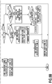
- FIG. 5 is a flowchart illustrating a calculation process of the estimated time Tc performed in the present embodiment.
- the flowchart illustrated in FIG. 5 is performed by the CPU 201.
- the CPU 201 determines on the basis of information stored in the memory 206 whether or not the print operation has been performed before N or more times (print operation performed on N or more labels). In the case where the CPU 201 determines that the print operation has not been performed in the past N or more times (on N or more labels), in S502, the CPU 502 sets a predetermined initial value as an estimated time Tc, and stores the estimated time Tc in the memory 206 relating the estimated time Tc to which ordinal number (which ordinal label) the print operation to be performed from now corresponds to. Also, in the case where N ⁇ 1, and the CPU 201 determines that one or more labels have been printed, the CPU 201 uses acquisition times in label print operations before the previous time to set the estimated time Tc.
- the CPU 201 sets, as the estimated time Tc, a median of acquisition times T in the N print operations performed just before the print operation to be performed from now, and stores the estimated time Tc in the memory 206 relating the estimated time Tc to which ordinal number (which ordinal label) the print operation to be performed from now corresponds to.
- FIGS. 6A and 6B , and FIGS. 7A and 7B are respectively diagrams illustrating results of calculating estimated times Tc from label acquisition times T.
- FIGS. 6A and 7A are tables illustrating pieces of information stored in the memory 206 in which the numbers of past printed labels, the acquisition times T, and the medians of the acquisition times are related to one another.
- FIGS. 6B and 7B are graphs illustrating the numbers of past printed labels, acquisition times T, and medians of the acquisition times.
- FIGS. 6A and 6B correspond to each other
- FIGS 7A and 7B correspond to each other.
- the estimated time Tc is equal to or less than the openable time T1
- a time necessary to print on a next label can be shortened to minimize a reduction in productivity while preventing a reduction in print quality.
- each of FIGS. 5 to 7A and 7B illustrates the example where to set the estimated time Tc, the medians are used; however, the estimated time Tc can also be calculated by a method using average values, or another method, and a method for calculating the estimated time can be arbitrarily set.
- a sampling number N used to calculate the estimated time Tc is set to a natural number equal to or more than 1, and can be appropriately set in consideration of a variation in acquisition time.
- this second embodiment also has the configuration illustrated in FIGS. 1 and 2 as with the first embodiment.
- the CPU 201 determines whether or not to perform the closing operation.
- the CPU 201 after performing a closing operation on the print head 120, the CPU 201 starts an opening operation of the ejection port surface 120a first depending on an estimated time Tc before the label detecting unit 113 detects that a label is taken out of the peeling part 112.
- the CPU 201 parallel performs an operation of switching the ejection port surface 120a of the print head from a close state to an open state by the capping mechanism 130 and an operation of conveying a label to be printed next backward. After ending the print operation on the label by the print head 120, the CPU 201 conveys backward the print medium until a label to be printed next reaches the print start position immediately after the label detecting sensor 113 has detected "no label" .
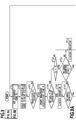
- FIGS. 8A and 8B are flowcharts illustrating an overall control operation in the second embodiment of the present invention
- FIG. 8 is a diagram showing a relationship between FIG. 8A and FIG. 8B .
- the flowcharts illustrated in FIG. 8A and 8B are performed by the CPU 201. Processing steps in S701 to 715, 717, 723, 724, and 725 illustrated in FIG. 8A and 8B are the same as those in S401 to 415, 416, 417, 418, and 419 in the first embodiment, and therefore description of them is omitted.
- Step S710 in the case where the CPU 201 determines that an estimated time Tc (estimated time Tc that is stored in the memory 206 and corresponds to a print operation in S702 (last performed print operation) is longer than an openable time T1 (NO in S710), the flow proceeds to S715, and the CPU 201 makes the capping mechanism 130 bring the ejection port surface 120a into the close state. Then, the CPU 201 determines in S716 whether or not the estimated time Tc exceeds a print preparation time (exceeds T2).
- the print preparation time T2 corresponds to the sum of a time necessary for the closing operation that switches the ejection port surface of the print head from the opening completion state to the close state, a time necessary for the opening operation that switches the ejection port surface from the close state to the opening completion state, and a time corresponding to a predetermined margin.
- the print preparation time T2 may not include the time corresponding to the predetermined margin.
- the flow proceeds to S718, where the CPU 201 determines whether or not a time (the estimated time Tc - the print preparation time T2) has passed after the end of the print operation on a label 103B.
- the CPU 201 starts the opening operation by the print capping mechanism 130, i.e., a print preparation operation making it possible for the print head 120 to perform printing, before an expected operation of taking out the label, as well as starting the measurement of an open time T4.
- the CPU 201 determines in S720 whether or not the label detecting sensor 113 has detected "no label" within the openable time T1 after the start of the measurement of the open time T4 in S719.
- the CPU 201 ends the measurement of the open time T4, as well as ending the measurement of an acquisition time T started in S704 to set an elapsed time from the start of the measurement to the end of the measurement as the acquisition time T, and storing the acquisition time T in the memory 206 relating the acquisition time T to which ordinal number the print operation in S702 (last performed print operation) corresponds to.
- the CPU 201 performs the back-feed of the print medium 103, and moves a label to be printed next to the print start position. After that, the flow proceeds to S701, and the CPU 201 sets an estimated time and starts the print operation on the label in the print position.
- the flow proceeds to S722, where the CPU 201 ends the measurement of the open time T4, as well as making the capping mechanism 130 perform the closing operation.
- the print preparation operation (opening operation) of the capping mechanism 130 is performed first in accordance with the estimated time Tc. This makes it possible to reduce a time necessary before printing on a next label to suppress a reduction in productivity while lessening a reduction in print quality due to thickening, solidification, or the like of ink in the print head.
- the printing apparatus using the print medium of which the mount is affixed with the labels is taken as an example to give the description; however, the present invention is also applicable to a printing apparatus that performs a print operation on a print medium other than the print medium used in each of the above-described embodiments.
- the present invention is not limited to the printing apparatus that as the post-process, performs the peeling operation that peels off a printed label 103B from the mount 103A as in the above-described first or second embodiments. That is, in the present invention, the configuration of the post-process is not limited to that described in each of the above-described embodiments as long as the post-process is performed after stopping a print operation.
- the discharge part serves as a site where the post-process is performed.
- the discharge part corresponds to the post-processing part of the present invention.
- the capping mechanism that closes and opens the ejection port surface of the print head is configured to include the head moving mechanism adapted to move the print head and the cap moving mechanism adapted to move the capping member.
- a time necessary for each of the closing operation and the opening operation is the sum of a head moving time and a capping member moving time.
- the capping mechanism can also be configured differently from the configuration in each of the above-described embodiments.
- the present invention can also be configured to perform the closing operation or the opening operation by moving only a print head with respect to a capping member placed in a fixed position. This makes it possible to simplify each of the shortening the time necessary for each of the operations.
- the printing apparatus that performs printing using the full line type inkjet print head while continuously conveying the print medium is taken as an example to give the description.
- the present invention is not limited to the printing apparatus having such a configuration, but is also applicable to a printing apparatus having another configuration. That is, the present invention is applicable to a serial type printing apparatus that intermittently conveys a print medium along a conveyance direction, as well as ejecting print liquid to perform a print operation while moving a print head in a direction orthogonal to the conveyance direction when the print medium is stopped.
- the present invention is, without limitation to the printing apparatus that prints on a continuous sheet, also applicable to a printing apparatus that sequentially prints on a cut sheet.
- the present invention intends to provide a printing apparatus that can lessen a reduction in ejection performance caused by thickening, solidification, or the like of print liquid in an ejection port of a printing unit even in the case of stopping a print operation by the printing unit to perform a post-process on a print medium.
- the printing apparatus includes a post-processing part configured to, in a state of stopping the print operation by the printing unit, perform the post-process on a printed print medium as well as including an open/close unit configured to selectively perform a closing operation or an opening operation of the ejection port provided in the printing unit. Further, when the print medium is stopped in the post-processing part, the open/close unit is controlled so as to bring the ejection port into a close state.
Landscapes
- Ink Jet (AREA)
- Printers Characterized By Their Purpose (AREA)
Applications Claiming Priority (1)
| Application Number | Priority Date | Filing Date | Title |
|---|---|---|---|
| JP2014064375A JP6267030B2 (ja) | 2014-03-26 | 2014-03-26 | 記録装置および記録方法 |
Publications (3)
| Publication Number | Publication Date |
|---|---|
| EP2939835A2 EP2939835A2 (en) | 2015-11-04 |
| EP2939835A3 EP2939835A3 (en) | 2016-01-06 |
| EP2939835B1 true EP2939835B1 (en) | 2021-05-05 |
Family
ID=52706095
Family Applications (1)
| Application Number | Title | Priority Date | Filing Date |
|---|---|---|---|
| EP15160824.7A Active EP2939835B1 (en) | 2014-03-26 | 2015-03-25 | Printing apparatus and printing method |
Country Status (3)
| Country | Link |
|---|---|
| US (1) | US9908341B2 (enExample) |
| EP (1) | EP2939835B1 (enExample) |
| JP (1) | JP6267030B2 (enExample) |
Families Citing this family (5)
| Publication number | Priority date | Publication date | Assignee | Title |
|---|---|---|---|---|
| US9457925B1 (en) * | 2015-04-21 | 2016-10-04 | Toshiba Tec Kabushiki Kaisha | Printing apparatus for controlling label mount rewind time, control method for controlling label mount rewind time and non-temporary recording medium |
| US10802463B1 (en) * | 2017-10-31 | 2020-10-13 | CMSI Technologies | Method of printing a tag and attaching the tag to a bag |
| US11814765B1 (en) * | 2019-04-23 | 2023-11-14 | CMSI Technologies | Method of printing a tag and attaching the tag to a bag |
| JP7455586B2 (ja) * | 2020-01-15 | 2024-03-26 | 東芝テック株式会社 | ラベルプリンタ及びラベルプリンタ制御プログラム |
| EP4023450A1 (de) * | 2020-12-29 | 2022-07-06 | Bizerba SE & Co. KG | Etikettendrucker |
Family Cites Families (13)
| Publication number | Priority date | Publication date | Assignee | Title |
|---|---|---|---|---|
| JPH08323987A (ja) | 1995-06-05 | 1996-12-10 | Citizen Watch Co Ltd | インクジェットプリンタのノズルキャッピング方法 |
| JP3535837B2 (ja) | 2000-07-21 | 2004-06-07 | キヤノン株式会社 | 印刷装置及び印刷システム及び制御方法及び記憶媒体及びプログラム |
| JP4307015B2 (ja) | 2002-06-04 | 2009-08-05 | キヤノン株式会社 | プリント装置及びその制御方法 |
| JP4027161B2 (ja) | 2002-06-04 | 2007-12-26 | キヤノン株式会社 | プリンタ装置及びその制御方法 |
| JP4208640B2 (ja) | 2002-06-04 | 2009-01-14 | キヤノン株式会社 | 印刷システムと印刷制御方法及び印刷装置とその制御方法 |
| JP2004013349A (ja) | 2002-06-04 | 2004-01-15 | Canon Inc | 撮像装置、記録システム及びその記録制御方法 |
| JP4714622B2 (ja) * | 2006-03-30 | 2011-06-29 | 富士フイルム株式会社 | インクジェット記録媒体の後加工方法および後加工装置を有する装置 |
| JP4807203B2 (ja) * | 2006-09-15 | 2011-11-02 | セイコーエプソン株式会社 | 両面記録装置及び記録方法 |
| JP2010023498A (ja) * | 2008-06-18 | 2010-02-04 | Canon Inc | インクジェット記録装置および記録画像の乾燥条件決定方法 |
| JP5644056B2 (ja) * | 2009-03-05 | 2014-12-24 | 株式会社リコー | 画像形成装置及びメンテナンス動作制御プログラム |
| JP2012192555A (ja) | 2011-03-15 | 2012-10-11 | Seiko Epson Corp | プリンターの制御方法及びプリンタードライバー |
| JP5648540B2 (ja) * | 2011-03-15 | 2015-01-07 | セイコーエプソン株式会社 | プリンターの制御方法及びプリンター |
| JP5891602B2 (ja) * | 2011-04-28 | 2016-03-23 | 東洋製罐株式会社 | インクジェット印刷装置及びこれを用いたシームレス缶の印刷方法 |
-
2014
- 2014-03-26 JP JP2014064375A patent/JP6267030B2/ja not_active Expired - Fee Related
-
2015
- 2015-03-25 EP EP15160824.7A patent/EP2939835B1/en active Active
- 2015-03-25 US US14/668,188 patent/US9908341B2/en active Active
Also Published As
| Publication number | Publication date |
|---|---|
| US20150273882A1 (en) | 2015-10-01 |
| EP2939835A2 (en) | 2015-11-04 |
| US9908341B2 (en) | 2018-03-06 |
| JP6267030B2 (ja) | 2018-01-24 |
| JP2015186846A (ja) | 2015-10-29 |
| EP2939835A3 (en) | 2016-01-06 |
Similar Documents
| Publication | Publication Date | Title |
|---|---|---|
| EP2939835B1 (en) | Printing apparatus and printing method | |
| US8882240B2 (en) | Inkjet printing apparatus and print head recovery method | |
| JP4906762B2 (ja) | 印刷装置及び印刷装置の制御方法 | |
| US20080218551A1 (en) | Ink jet printing method and ink jet printing apparatus | |
| EP2896505A2 (en) | Thermal printer | |
| EP3257674A1 (en) | Image recording device, and image recording method | |
| US9579908B2 (en) | Sheet conveying apparatus | |
| JP4847249B2 (ja) | 画像記録装置、その装置によるインク予備吐出方法及びプログラム | |
| JP3674577B2 (ja) | インクジェット式プリンタ | |
| JP6612076B2 (ja) | インクジェット印刷装置及びそのフラッシング方法 | |
| JP5577774B2 (ja) | 画像形成装置 | |
| JP6299258B2 (ja) | 印刷装置、及び、印刷装置の制御方法 | |
| JP4586570B2 (ja) | 印刷装置、印刷方法、及び、プログラム | |
| JP4304218B2 (ja) | 印刷装置、印刷方法、および、プログラム | |
| JP5760911B2 (ja) | 液体吐出装置 | |
| JP2015066719A (ja) | 印刷装置、及び、印刷装置の制御方法 | |
| JP6366945B2 (ja) | 印刷制御装置及び印刷装置、インクジェット印刷装置並びに印刷方法 | |
| JP2012011569A (ja) | プリンター及びその制御方法 | |
| JP2015009388A (ja) | 記録装置および記録方法 | |
| JP2013199037A (ja) | 画像形成装置 | |
| EP2993049B1 (en) | Image forming device and image forming method | |
| JP6667222B2 (ja) | 記録装置および記録方法 | |
| JP2012035525A (ja) | インクジェット画像形成装置 | |
| JP4684462B2 (ja) | プリント装置 | |
| JP2012218304A (ja) | 印刷装置、その制御方法及びプログラム |
Legal Events
| Date | Code | Title | Description |
|---|---|---|---|
| PUAI | Public reference made under article 153(3) epc to a published international application that has entered the european phase |
Free format text: ORIGINAL CODE: 0009012 |
|
| 17P | Request for examination filed |
Effective date: 20150325 |
|
| AK | Designated contracting states |
Kind code of ref document: A2 Designated state(s): AL AT BE BG CH CY CZ DE DK EE ES FI FR GB GR HR HU IE IS IT LI LT LU LV MC MK MT NL NO PL PT RO RS SE SI SK SM TR |
|
| AX | Request for extension of the european patent |
Extension state: BA ME |
|
| PUAL | Search report despatched |
Free format text: ORIGINAL CODE: 0009013 |
|
| AK | Designated contracting states |
Kind code of ref document: A3 Designated state(s): AL AT BE BG CH CY CZ DE DK EE ES FI FR GB GR HR HU IE IS IT LI LT LU LV MC MK MT NL NO PL PT RO RS SE SI SK SM TR |
|
| AX | Request for extension of the european patent |
Extension state: BA ME |
|
| RIC1 | Information provided on ipc code assigned before grant |
Ipc: B41J 11/00 20060101ALI20151203BHEP Ipc: B41J 3/407 20060101ALI20151203BHEP Ipc: B41J 2/165 20060101AFI20151203BHEP Ipc: G06K 15/02 20060101ALI20151203BHEP |
|
| RAP1 | Party data changed (applicant data changed or rights of an application transferred) |
Owner name: CANON FINETECH NISCA INC. |
|
| STAA | Information on the status of an ep patent application or granted ep patent |
Free format text: STATUS: EXAMINATION IS IN PROGRESS |
|
| 17Q | First examination report despatched |
Effective date: 20200117 |
|
| GRAP | Despatch of communication of intention to grant a patent |
Free format text: ORIGINAL CODE: EPIDOSNIGR1 |
|
| STAA | Information on the status of an ep patent application or granted ep patent |
Free format text: STATUS: GRANT OF PATENT IS INTENDED |
|
| INTG | Intention to grant announced |
Effective date: 20201124 |
|
| GRAS | Grant fee paid |
Free format text: ORIGINAL CODE: EPIDOSNIGR3 |
|
| GRAA | (expected) grant |
Free format text: ORIGINAL CODE: 0009210 |
|
| STAA | Information on the status of an ep patent application or granted ep patent |
Free format text: STATUS: THE PATENT HAS BEEN GRANTED |
|
| AK | Designated contracting states |
Kind code of ref document: B1 Designated state(s): AL AT BE BG CH CY CZ DE DK EE ES FI FR GB GR HR HU IE IS IT LI LT LU LV MC MK MT NL NO PL PT RO RS SE SI SK SM TR |
|
| REG | Reference to a national code |
Ref country code: GB Ref legal event code: FG4D |
|
| REG | Reference to a national code |
Ref country code: CH Ref legal event code: EP |
|
| REG | Reference to a national code |
Ref country code: AT Ref legal event code: REF Ref document number: 1389323 Country of ref document: AT Kind code of ref document: T Effective date: 20210515 |
|
| REG | Reference to a national code |
Ref country code: IE Ref legal event code: FG4D |
|
| REG | Reference to a national code |
Ref country code: DE Ref legal event code: R096 Ref document number: 602015068872 Country of ref document: DE |
|
| REG | Reference to a national code |
Ref country code: LT Ref legal event code: MG9D |
|
| REG | Reference to a national code |
Ref country code: AT Ref legal event code: MK05 Ref document number: 1389323 Country of ref document: AT Kind code of ref document: T Effective date: 20210505 |
|
| PG25 | Lapsed in a contracting state [announced via postgrant information from national office to epo] |
Ref country code: AT Free format text: LAPSE BECAUSE OF FAILURE TO SUBMIT A TRANSLATION OF THE DESCRIPTION OR TO PAY THE FEE WITHIN THE PRESCRIBED TIME-LIMIT Effective date: 20210505 Ref country code: BG Free format text: LAPSE BECAUSE OF FAILURE TO SUBMIT A TRANSLATION OF THE DESCRIPTION OR TO PAY THE FEE WITHIN THE PRESCRIBED TIME-LIMIT Effective date: 20210805 Ref country code: FI Free format text: LAPSE BECAUSE OF FAILURE TO SUBMIT A TRANSLATION OF THE DESCRIPTION OR TO PAY THE FEE WITHIN THE PRESCRIBED TIME-LIMIT Effective date: 20210505 Ref country code: LT Free format text: LAPSE BECAUSE OF FAILURE TO SUBMIT A TRANSLATION OF THE DESCRIPTION OR TO PAY THE FEE WITHIN THE PRESCRIBED TIME-LIMIT Effective date: 20210505 Ref country code: HR Free format text: LAPSE BECAUSE OF FAILURE TO SUBMIT A TRANSLATION OF THE DESCRIPTION OR TO PAY THE FEE WITHIN THE PRESCRIBED TIME-LIMIT Effective date: 20210505 |
|
| PG25 | Lapsed in a contracting state [announced via postgrant information from national office to epo] |
Ref country code: LV Free format text: LAPSE BECAUSE OF FAILURE TO SUBMIT A TRANSLATION OF THE DESCRIPTION OR TO PAY THE FEE WITHIN THE PRESCRIBED TIME-LIMIT Effective date: 20210505 Ref country code: GR Free format text: LAPSE BECAUSE OF FAILURE TO SUBMIT A TRANSLATION OF THE DESCRIPTION OR TO PAY THE FEE WITHIN THE PRESCRIBED TIME-LIMIT Effective date: 20210806 Ref country code: IS Free format text: LAPSE BECAUSE OF FAILURE TO SUBMIT A TRANSLATION OF THE DESCRIPTION OR TO PAY THE FEE WITHIN THE PRESCRIBED TIME-LIMIT Effective date: 20210905 Ref country code: NO Free format text: LAPSE BECAUSE OF FAILURE TO SUBMIT A TRANSLATION OF THE DESCRIPTION OR TO PAY THE FEE WITHIN THE PRESCRIBED TIME-LIMIT Effective date: 20210805 Ref country code: PL Free format text: LAPSE BECAUSE OF FAILURE TO SUBMIT A TRANSLATION OF THE DESCRIPTION OR TO PAY THE FEE WITHIN THE PRESCRIBED TIME-LIMIT Effective date: 20210505 Ref country code: PT Free format text: LAPSE BECAUSE OF FAILURE TO SUBMIT A TRANSLATION OF THE DESCRIPTION OR TO PAY THE FEE WITHIN THE PRESCRIBED TIME-LIMIT Effective date: 20210906 Ref country code: ES Free format text: LAPSE BECAUSE OF FAILURE TO SUBMIT A TRANSLATION OF THE DESCRIPTION OR TO PAY THE FEE WITHIN THE PRESCRIBED TIME-LIMIT Effective date: 20210505 Ref country code: RS Free format text: LAPSE BECAUSE OF FAILURE TO SUBMIT A TRANSLATION OF THE DESCRIPTION OR TO PAY THE FEE WITHIN THE PRESCRIBED TIME-LIMIT Effective date: 20210505 Ref country code: SE Free format text: LAPSE BECAUSE OF FAILURE TO SUBMIT A TRANSLATION OF THE DESCRIPTION OR TO PAY THE FEE WITHIN THE PRESCRIBED TIME-LIMIT Effective date: 20210505 |
|
| REG | Reference to a national code |
Ref country code: NL Ref legal event code: MP Effective date: 20210505 |
|
| PG25 | Lapsed in a contracting state [announced via postgrant information from national office to epo] |
Ref country code: NL Free format text: LAPSE BECAUSE OF FAILURE TO SUBMIT A TRANSLATION OF THE DESCRIPTION OR TO PAY THE FEE WITHIN THE PRESCRIBED TIME-LIMIT Effective date: 20210505 |
|
| PG25 | Lapsed in a contracting state [announced via postgrant information from national office to epo] |
Ref country code: CZ Free format text: LAPSE BECAUSE OF FAILURE TO SUBMIT A TRANSLATION OF THE DESCRIPTION OR TO PAY THE FEE WITHIN THE PRESCRIBED TIME-LIMIT Effective date: 20210505 Ref country code: EE Free format text: LAPSE BECAUSE OF FAILURE TO SUBMIT A TRANSLATION OF THE DESCRIPTION OR TO PAY THE FEE WITHIN THE PRESCRIBED TIME-LIMIT Effective date: 20210505 Ref country code: DK Free format text: LAPSE BECAUSE OF FAILURE TO SUBMIT A TRANSLATION OF THE DESCRIPTION OR TO PAY THE FEE WITHIN THE PRESCRIBED TIME-LIMIT Effective date: 20210505 Ref country code: SM Free format text: LAPSE BECAUSE OF FAILURE TO SUBMIT A TRANSLATION OF THE DESCRIPTION OR TO PAY THE FEE WITHIN THE PRESCRIBED TIME-LIMIT Effective date: 20210505 Ref country code: SK Free format text: LAPSE BECAUSE OF FAILURE TO SUBMIT A TRANSLATION OF THE DESCRIPTION OR TO PAY THE FEE WITHIN THE PRESCRIBED TIME-LIMIT Effective date: 20210505 Ref country code: RO Free format text: LAPSE BECAUSE OF FAILURE TO SUBMIT A TRANSLATION OF THE DESCRIPTION OR TO PAY THE FEE WITHIN THE PRESCRIBED TIME-LIMIT Effective date: 20210505 |
|
| REG | Reference to a national code |
Ref country code: DE Ref legal event code: R097 Ref document number: 602015068872 Country of ref document: DE |
|
| PLBE | No opposition filed within time limit |
Free format text: ORIGINAL CODE: 0009261 |
|
| STAA | Information on the status of an ep patent application or granted ep patent |
Free format text: STATUS: NO OPPOSITION FILED WITHIN TIME LIMIT |
|
| 26N | No opposition filed |
Effective date: 20220208 |
|
| PG25 | Lapsed in a contracting state [announced via postgrant information from national office to epo] |
Ref country code: IS Free format text: LAPSE BECAUSE OF FAILURE TO SUBMIT A TRANSLATION OF THE DESCRIPTION OR TO PAY THE FEE WITHIN THE PRESCRIBED TIME-LIMIT Effective date: 20210905 Ref country code: AL Free format text: LAPSE BECAUSE OF FAILURE TO SUBMIT A TRANSLATION OF THE DESCRIPTION OR TO PAY THE FEE WITHIN THE PRESCRIBED TIME-LIMIT Effective date: 20210505 |
|
| PG25 | Lapsed in a contracting state [announced via postgrant information from national office to epo] |
Ref country code: IT Free format text: LAPSE BECAUSE OF FAILURE TO SUBMIT A TRANSLATION OF THE DESCRIPTION OR TO PAY THE FEE WITHIN THE PRESCRIBED TIME-LIMIT Effective date: 20210505 |
|
| PG25 | Lapsed in a contracting state [announced via postgrant information from national office to epo] |
Ref country code: MC Free format text: LAPSE BECAUSE OF FAILURE TO SUBMIT A TRANSLATION OF THE DESCRIPTION OR TO PAY THE FEE WITHIN THE PRESCRIBED TIME-LIMIT Effective date: 20210505 |
|
| REG | Reference to a national code |
Ref country code: CH Ref legal event code: PL |
|
| REG | Reference to a national code |
Ref country code: BE Ref legal event code: MM Effective date: 20220331 |
|
| PG25 | Lapsed in a contracting state [announced via postgrant information from national office to epo] |
Ref country code: LU Free format text: LAPSE BECAUSE OF NON-PAYMENT OF DUE FEES Effective date: 20220325 Ref country code: LI Free format text: LAPSE BECAUSE OF NON-PAYMENT OF DUE FEES Effective date: 20220331 Ref country code: IE Free format text: LAPSE BECAUSE OF NON-PAYMENT OF DUE FEES Effective date: 20220325 Ref country code: CH Free format text: LAPSE BECAUSE OF NON-PAYMENT OF DUE FEES Effective date: 20220331 |
|
| PG25 | Lapsed in a contracting state [announced via postgrant information from national office to epo] |
Ref country code: BE Free format text: LAPSE BECAUSE OF NON-PAYMENT OF DUE FEES Effective date: 20220331 |
|
| PGFP | Annual fee paid to national office [announced via postgrant information from national office to epo] |
Ref country code: FR Payment date: 20230208 Year of fee payment: 9 |
|
| PGFP | Annual fee paid to national office [announced via postgrant information from national office to epo] |
Ref country code: GB Payment date: 20230202 Year of fee payment: 9 Ref country code: DE Payment date: 20230131 Year of fee payment: 9 |
|
| PG25 | Lapsed in a contracting state [announced via postgrant information from national office to epo] |
Ref country code: HU Free format text: LAPSE BECAUSE OF FAILURE TO SUBMIT A TRANSLATION OF THE DESCRIPTION OR TO PAY THE FEE WITHIN THE PRESCRIBED TIME-LIMIT; INVALID AB INITIO Effective date: 20150325 |
|
| PG25 | Lapsed in a contracting state [announced via postgrant information from national office to epo] |
Ref country code: MK Free format text: LAPSE BECAUSE OF FAILURE TO SUBMIT A TRANSLATION OF THE DESCRIPTION OR TO PAY THE FEE WITHIN THE PRESCRIBED TIME-LIMIT Effective date: 20210505 Ref country code: CY Free format text: LAPSE BECAUSE OF FAILURE TO SUBMIT A TRANSLATION OF THE DESCRIPTION OR TO PAY THE FEE WITHIN THE PRESCRIBED TIME-LIMIT Effective date: 20210505 |
|
| PG25 | Lapsed in a contracting state [announced via postgrant information from national office to epo] |
Ref country code: TR Free format text: LAPSE BECAUSE OF FAILURE TO SUBMIT A TRANSLATION OF THE DESCRIPTION OR TO PAY THE FEE WITHIN THE PRESCRIBED TIME-LIMIT Effective date: 20210505 |
|
| PG25 | Lapsed in a contracting state [announced via postgrant information from national office to epo] |
Ref country code: MT Free format text: LAPSE BECAUSE OF FAILURE TO SUBMIT A TRANSLATION OF THE DESCRIPTION OR TO PAY THE FEE WITHIN THE PRESCRIBED TIME-LIMIT Effective date: 20210505 |
|
| REG | Reference to a national code |
Ref country code: DE Ref legal event code: R119 Ref document number: 602015068872 Country of ref document: DE |
|
| GBPC | Gb: european patent ceased through non-payment of renewal fee |
Effective date: 20240325 |
|
| PG25 | Lapsed in a contracting state [announced via postgrant information from national office to epo] |
Ref country code: DE Free format text: LAPSE BECAUSE OF NON-PAYMENT OF DUE FEES Effective date: 20241001 |
|
| PG25 | Lapsed in a contracting state [announced via postgrant information from national office to epo] |
Ref country code: GB Free format text: LAPSE BECAUSE OF NON-PAYMENT OF DUE FEES Effective date: 20240325 |
|
| PG25 | Lapsed in a contracting state [announced via postgrant information from national office to epo] |
Ref country code: FR Free format text: LAPSE BECAUSE OF NON-PAYMENT OF DUE FEES Effective date: 20240331 |
|
| PG25 | Lapsed in a contracting state [announced via postgrant information from national office to epo] |
Ref country code: GB Free format text: LAPSE BECAUSE OF NON-PAYMENT OF DUE FEES Effective date: 20240325 Ref country code: FR Free format text: LAPSE BECAUSE OF NON-PAYMENT OF DUE FEES Effective date: 20240331 Ref country code: DE Free format text: LAPSE BECAUSE OF NON-PAYMENT OF DUE FEES Effective date: 20241001 |