EP2938507B1 - System and method for monitoring an estimated wheel speed of a vehicle using a transmission output shaft sensor - Google Patents
System and method for monitoring an estimated wheel speed of a vehicle using a transmission output shaft sensor Download PDFInfo
- Publication number
- EP2938507B1 EP2938507B1 EP13821239.4A EP13821239A EP2938507B1 EP 2938507 B1 EP2938507 B1 EP 2938507B1 EP 13821239 A EP13821239 A EP 13821239A EP 2938507 B1 EP2938507 B1 EP 2938507B1
- Authority
- EP
- European Patent Office
- Prior art keywords
- wheel
- wheel speed
- speed value
- value
- deviation
- Prior art date
- Legal status (The legal status is an assumption and is not a legal conclusion. Google has not performed a legal analysis and makes no representation as to the accuracy of the status listed.)
- Not-in-force
Links
- 238000012544 monitoring process Methods 0.000 title claims description 66
- 238000000034 method Methods 0.000 title claims description 19
- 230000005540 biological transmission Effects 0.000 title claims description 10
- 238000005259 measurement Methods 0.000 claims description 4
- 238000004481 total suppression of sideband Methods 0.000 description 23
- 238000004364 calculation method Methods 0.000 description 9
- 238000010276 construction Methods 0.000 description 6
- 230000035945 sensitivity Effects 0.000 description 2
- 238000010586 diagram Methods 0.000 description 1
- 238000010200 validation analysis Methods 0.000 description 1
Images

Classifications
-
- G—PHYSICS
- G07—CHECKING-DEVICES
- G07C—TIME OR ATTENDANCE REGISTERS; REGISTERING OR INDICATING THE WORKING OF MACHINES; GENERATING RANDOM NUMBERS; VOTING OR LOTTERY APPARATUS; ARRANGEMENTS, SYSTEMS OR APPARATUS FOR CHECKING NOT PROVIDED FOR ELSEWHERE
- G07C5/00—Registering or indicating the working of vehicles
- G07C5/08—Registering or indicating performance data other than driving, working, idle, or waiting time, with or without registering driving, working, idle or waiting time
- G07C5/0816—Indicating performance data, e.g. occurrence of a malfunction
-
- B—PERFORMING OPERATIONS; TRANSPORTING
- B60—VEHICLES IN GENERAL
- B60G—VEHICLE SUSPENSION ARRANGEMENTS
- B60G17/00—Resilient suspensions having means for adjusting the spring or vibration-damper characteristics, for regulating the distance between a supporting surface and a sprung part of vehicle or for locking suspension during use to meet varying vehicular or surface conditions, e.g. due to speed or load
- B60G17/015—Resilient suspensions having means for adjusting the spring or vibration-damper characteristics, for regulating the distance between a supporting surface and a sprung part of vehicle or for locking suspension during use to meet varying vehicular or surface conditions, e.g. due to speed or load the regulating means comprising electric or electronic elements
- B60G17/018—Resilient suspensions having means for adjusting the spring or vibration-damper characteristics, for regulating the distance between a supporting surface and a sprung part of vehicle or for locking suspension during use to meet varying vehicular or surface conditions, e.g. due to speed or load the regulating means comprising electric or electronic elements characterised by the use of a specific signal treatment or control method
- B60G17/0182—Resilient suspensions having means for adjusting the spring or vibration-damper characteristics, for regulating the distance between a supporting surface and a sprung part of vehicle or for locking suspension during use to meet varying vehicular or surface conditions, e.g. due to speed or load the regulating means comprising electric or electronic elements characterised by the use of a specific signal treatment or control method involving parameter estimation, e.g. observer, Kalman filter
-
- B—PERFORMING OPERATIONS; TRANSPORTING
- B60—VEHICLES IN GENERAL
- B60G—VEHICLE SUSPENSION ARRANGEMENTS
- B60G17/00—Resilient suspensions having means for adjusting the spring or vibration-damper characteristics, for regulating the distance between a supporting surface and a sprung part of vehicle or for locking suspension during use to meet varying vehicular or surface conditions, e.g. due to speed or load
- B60G17/015—Resilient suspensions having means for adjusting the spring or vibration-damper characteristics, for regulating the distance between a supporting surface and a sprung part of vehicle or for locking suspension during use to meet varying vehicular or surface conditions, e.g. due to speed or load the regulating means comprising electric or electronic elements
- B60G17/018—Resilient suspensions having means for adjusting the spring or vibration-damper characteristics, for regulating the distance between a supporting surface and a sprung part of vehicle or for locking suspension during use to meet varying vehicular or surface conditions, e.g. due to speed or load the regulating means comprising electric or electronic elements characterised by the use of a specific signal treatment or control method
- B60G17/0185—Resilient suspensions having means for adjusting the spring or vibration-damper characteristics, for regulating the distance between a supporting surface and a sprung part of vehicle or for locking suspension during use to meet varying vehicular or surface conditions, e.g. due to speed or load the regulating means comprising electric or electronic elements characterised by the use of a specific signal treatment or control method for failure detection
-
- B—PERFORMING OPERATIONS; TRANSPORTING
- B60—VEHICLES IN GENERAL
- B60G—VEHICLE SUSPENSION ARRANGEMENTS
- B60G17/00—Resilient suspensions having means for adjusting the spring or vibration-damper characteristics, for regulating the distance between a supporting surface and a sprung part of vehicle or for locking suspension during use to meet varying vehicular or surface conditions, e.g. due to speed or load
- B60G17/015—Resilient suspensions having means for adjusting the spring or vibration-damper characteristics, for regulating the distance between a supporting surface and a sprung part of vehicle or for locking suspension during use to meet varying vehicular or surface conditions, e.g. due to speed or load the regulating means comprising electric or electronic elements
- B60G17/019—Resilient suspensions having means for adjusting the spring or vibration-damper characteristics, for regulating the distance between a supporting surface and a sprung part of vehicle or for locking suspension during use to meet varying vehicular or surface conditions, e.g. due to speed or load the regulating means comprising electric or electronic elements characterised by the type of sensor or the arrangement thereof
-
- B—PERFORMING OPERATIONS; TRANSPORTING
- B60—VEHICLES IN GENERAL
- B60G—VEHICLE SUSPENSION ARRANGEMENTS
- B60G17/00—Resilient suspensions having means for adjusting the spring or vibration-damper characteristics, for regulating the distance between a supporting surface and a sprung part of vehicle or for locking suspension during use to meet varying vehicular or surface conditions, e.g. due to speed or load
- B60G17/015—Resilient suspensions having means for adjusting the spring or vibration-damper characteristics, for regulating the distance between a supporting surface and a sprung part of vehicle or for locking suspension during use to meet varying vehicular or surface conditions, e.g. due to speed or load the regulating means comprising electric or electronic elements
- B60G17/0195—Resilient suspensions having means for adjusting the spring or vibration-damper characteristics, for regulating the distance between a supporting surface and a sprung part of vehicle or for locking suspension during use to meet varying vehicular or surface conditions, e.g. due to speed or load the regulating means comprising electric or electronic elements characterised by the regulation being combined with other vehicle control systems
-
- B—PERFORMING OPERATIONS; TRANSPORTING
- B60—VEHICLES IN GENERAL
- B60T—VEHICLE BRAKE CONTROL SYSTEMS OR PARTS THEREOF; BRAKE CONTROL SYSTEMS OR PARTS THEREOF, IN GENERAL; ARRANGEMENT OF BRAKING ELEMENTS ON VEHICLES IN GENERAL; PORTABLE DEVICES FOR PREVENTING UNWANTED MOVEMENT OF VEHICLES; VEHICLE MODIFICATIONS TO FACILITATE COOLING OF BRAKES
- B60T8/00—Arrangements for adjusting wheel-braking force to meet varying vehicular or ground-surface conditions, e.g. limiting or varying distribution of braking force
- B60T8/32—Arrangements for adjusting wheel-braking force to meet varying vehicular or ground-surface conditions, e.g. limiting or varying distribution of braking force responsive to a speed condition, e.g. acceleration or deceleration
- B60T8/88—Arrangements for adjusting wheel-braking force to meet varying vehicular or ground-surface conditions, e.g. limiting or varying distribution of braking force responsive to a speed condition, e.g. acceleration or deceleration with failure responsive means, i.e. means for detecting and indicating faulty operation of the speed responsive control means
- B60T8/885—Arrangements for adjusting wheel-braking force to meet varying vehicular or ground-surface conditions, e.g. limiting or varying distribution of braking force responsive to a speed condition, e.g. acceleration or deceleration with failure responsive means, i.e. means for detecting and indicating faulty operation of the speed responsive control means using electrical circuitry
-
- B—PERFORMING OPERATIONS; TRANSPORTING
- B60—VEHICLES IN GENERAL
- B60W—CONJOINT CONTROL OF VEHICLE SUB-UNITS OF DIFFERENT TYPE OR DIFFERENT FUNCTION; CONTROL SYSTEMS SPECIALLY ADAPTED FOR HYBRID VEHICLES; ROAD VEHICLE DRIVE CONTROL SYSTEMS FOR PURPOSES NOT RELATED TO THE CONTROL OF A PARTICULAR SUB-UNIT
- B60W40/00—Estimation or calculation of non-directly measurable driving parameters for road vehicle drive control systems not related to the control of a particular sub unit, e.g. by using mathematical models
- B60W40/10—Estimation or calculation of non-directly measurable driving parameters for road vehicle drive control systems not related to the control of a particular sub unit, e.g. by using mathematical models related to vehicle motion
-
- B—PERFORMING OPERATIONS; TRANSPORTING
- B60—VEHICLES IN GENERAL
- B60W—CONJOINT CONTROL OF VEHICLE SUB-UNITS OF DIFFERENT TYPE OR DIFFERENT FUNCTION; CONTROL SYSTEMS SPECIALLY ADAPTED FOR HYBRID VEHICLES; ROAD VEHICLE DRIVE CONTROL SYSTEMS FOR PURPOSES NOT RELATED TO THE CONTROL OF A PARTICULAR SUB-UNIT
- B60W50/00—Details of control systems for road vehicle drive control not related to the control of a particular sub-unit, e.g. process diagnostic or vehicle driver interfaces
- B60W50/02—Ensuring safety in case of control system failures, e.g. by diagnosing, circumventing or fixing failures
- B60W50/0205—Diagnosing or detecting failures; Failure detection models
-
- G—PHYSICS
- G01—MEASURING; TESTING
- G01P—MEASURING LINEAR OR ANGULAR SPEED, ACCELERATION, DECELERATION, OR SHOCK; INDICATING PRESENCE, ABSENCE, OR DIRECTION, OF MOVEMENT
- G01P21/00—Testing or calibrating of apparatus or devices covered by the preceding groups
- G01P21/02—Testing or calibrating of apparatus or devices covered by the preceding groups of speedometers
-
- B—PERFORMING OPERATIONS; TRANSPORTING
- B60—VEHICLES IN GENERAL
- B60G—VEHICLE SUSPENSION ARRANGEMENTS
- B60G2400/00—Indexing codes relating to detected, measured or calculated conditions or factors
- B60G2400/20—Speed
- B60G2400/208—Speed of wheel rotation
-
- B—PERFORMING OPERATIONS; TRANSPORTING
- B60—VEHICLES IN GENERAL
- B60G—VEHICLE SUSPENSION ARRANGEMENTS
- B60G2400/00—Indexing codes relating to detected, measured or calculated conditions or factors
- B60G2400/30—Propulsion unit conditions
- B60G2400/302—Selected gear ratio; Transmission function
-
- B—PERFORMING OPERATIONS; TRANSPORTING
- B60—VEHICLES IN GENERAL
- B60G—VEHICLE SUSPENSION ARRANGEMENTS
- B60G2600/00—Indexing codes relating to particular elements, systems or processes used on suspension systems or suspension control systems
- B60G2600/02—Retarders, delaying means, dead zones, threshold values, cut-off frequency, timer interruption
-
- B—PERFORMING OPERATIONS; TRANSPORTING
- B60—VEHICLES IN GENERAL
- B60G—VEHICLE SUSPENSION ARRANGEMENTS
- B60G2600/00—Indexing codes relating to particular elements, systems or processes used on suspension systems or suspension control systems
- B60G2600/04—Means for informing, instructing or displaying
- B60G2600/042—Monitoring means
-
- B—PERFORMING OPERATIONS; TRANSPORTING
- B60—VEHICLES IN GENERAL
- B60G—VEHICLE SUSPENSION ARRANGEMENTS
- B60G2600/00—Indexing codes relating to particular elements, systems or processes used on suspension systems or suspension control systems
- B60G2600/08—Failure or malfunction detecting means
- B60G2600/082—Sensor drift
-
- B—PERFORMING OPERATIONS; TRANSPORTING
- B60—VEHICLES IN GENERAL
- B60G—VEHICLE SUSPENSION ARRANGEMENTS
- B60G2600/00—Indexing codes relating to particular elements, systems or processes used on suspension systems or suspension control systems
- B60G2600/12—Sampling or average detecting; Addition or substraction
-
- B—PERFORMING OPERATIONS; TRANSPORTING
- B60—VEHICLES IN GENERAL
- B60G—VEHICLE SUSPENSION ARRANGEMENTS
- B60G2800/00—Indexing codes relating to the type of movement or to the condition of the vehicle and to the end result to be achieved by the control action
- B60G2800/70—Estimating or calculating vehicle parameters or state variables
- B60G2800/702—Improving accuracy of a sensor signal
-
- B—PERFORMING OPERATIONS; TRANSPORTING
- B60—VEHICLES IN GENERAL
- B60G—VEHICLE SUSPENSION ARRANGEMENTS
- B60G2800/00—Indexing codes relating to the type of movement or to the condition of the vehicle and to the end result to be achieved by the control action
- B60G2800/80—Detection or control after a system or component failure
- B60G2800/802—Diagnostics
-
- B—PERFORMING OPERATIONS; TRANSPORTING
- B60—VEHICLES IN GENERAL
- B60G—VEHICLE SUSPENSION ARRANGEMENTS
- B60G2800/00—Indexing codes relating to the type of movement or to the condition of the vehicle and to the end result to be achieved by the control action
- B60G2800/90—System Controller type
- B60G2800/94—Electronic Stability Program (ESP, i.e. ABS+ASC+EMS)
-
- B—PERFORMING OPERATIONS; TRANSPORTING
- B60—VEHICLES IN GENERAL
- B60T—VEHICLE BRAKE CONTROL SYSTEMS OR PARTS THEREOF; BRAKE CONTROL SYSTEMS OR PARTS THEREOF, IN GENERAL; ARRANGEMENT OF BRAKING ELEMENTS ON VEHICLES IN GENERAL; PORTABLE DEVICES FOR PREVENTING UNWANTED MOVEMENT OF VEHICLES; VEHICLE MODIFICATIONS TO FACILITATE COOLING OF BRAKES
- B60T2260/00—Interaction of vehicle brake system with other systems
- B60T2260/04—Automatic transmission
-
- B—PERFORMING OPERATIONS; TRANSPORTING
- B60—VEHICLES IN GENERAL
- B60T—VEHICLE BRAKE CONTROL SYSTEMS OR PARTS THEREOF; BRAKE CONTROL SYSTEMS OR PARTS THEREOF, IN GENERAL; ARRANGEMENT OF BRAKING ELEMENTS ON VEHICLES IN GENERAL; PORTABLE DEVICES FOR PREVENTING UNWANTED MOVEMENT OF VEHICLES; VEHICLE MODIFICATIONS TO FACILITATE COOLING OF BRAKES
- B60T2270/00—Further aspects of brake control systems not otherwise provided for
- B60T2270/40—Failsafe aspects of brake control systems
- B60T2270/413—Plausibility monitoring, cross check, redundancy
-
- B—PERFORMING OPERATIONS; TRANSPORTING
- B60—VEHICLES IN GENERAL
- B60T—VEHICLE BRAKE CONTROL SYSTEMS OR PARTS THEREOF; BRAKE CONTROL SYSTEMS OR PARTS THEREOF, IN GENERAL; ARRANGEMENT OF BRAKING ELEMENTS ON VEHICLES IN GENERAL; PORTABLE DEVICES FOR PREVENTING UNWANTED MOVEMENT OF VEHICLES; VEHICLE MODIFICATIONS TO FACILITATE COOLING OF BRAKES
- B60T2270/00—Further aspects of brake control systems not otherwise provided for
- B60T2270/40—Failsafe aspects of brake control systems
- B60T2270/416—Wheel speed sensor failure
-
- B—PERFORMING OPERATIONS; TRANSPORTING
- B60—VEHICLES IN GENERAL
- B60W—CONJOINT CONTROL OF VEHICLE SUB-UNITS OF DIFFERENT TYPE OR DIFFERENT FUNCTION; CONTROL SYSTEMS SPECIALLY ADAPTED FOR HYBRID VEHICLES; ROAD VEHICLE DRIVE CONTROL SYSTEMS FOR PURPOSES NOT RELATED TO THE CONTROL OF A PARTICULAR SUB-UNIT
- B60W50/00—Details of control systems for road vehicle drive control not related to the control of a particular sub-unit, e.g. process diagnostic or vehicle driver interfaces
- B60W50/02—Ensuring safety in case of control system failures, e.g. by diagnosing, circumventing or fixing failures
- B60W50/0205—Diagnosing or detecting failures; Failure detection models
- B60W2050/0215—Sensor drifts or sensor failures
-
- B—PERFORMING OPERATIONS; TRANSPORTING
- B60—VEHICLES IN GENERAL
- B60W—CONJOINT CONTROL OF VEHICLE SUB-UNITS OF DIFFERENT TYPE OR DIFFERENT FUNCTION; CONTROL SYSTEMS SPECIALLY ADAPTED FOR HYBRID VEHICLES; ROAD VEHICLE DRIVE CONTROL SYSTEMS FOR PURPOSES NOT RELATED TO THE CONTROL OF A PARTICULAR SUB-UNIT
- B60W2400/00—Indexing codes relating to detected, measured or calculated conditions or factors
-
- B—PERFORMING OPERATIONS; TRANSPORTING
- B60—VEHICLES IN GENERAL
- B60W—CONJOINT CONTROL OF VEHICLE SUB-UNITS OF DIFFERENT TYPE OR DIFFERENT FUNCTION; CONTROL SYSTEMS SPECIALLY ADAPTED FOR HYBRID VEHICLES; ROAD VEHICLE DRIVE CONTROL SYSTEMS FOR PURPOSES NOT RELATED TO THE CONTROL OF A PARTICULAR SUB-UNIT
- B60W2510/00—Input parameters relating to a particular sub-units
- B60W2510/10—Change speed gearings
- B60W2510/104—Output speed
-
- B—PERFORMING OPERATIONS; TRANSPORTING
- B60—VEHICLES IN GENERAL
- B60W—CONJOINT CONTROL OF VEHICLE SUB-UNITS OF DIFFERENT TYPE OR DIFFERENT FUNCTION; CONTROL SYSTEMS SPECIALLY ADAPTED FOR HYBRID VEHICLES; ROAD VEHICLE DRIVE CONTROL SYSTEMS FOR PURPOSES NOT RELATED TO THE CONTROL OF A PARTICULAR SUB-UNIT
- B60W2520/00—Input parameters relating to overall vehicle dynamics
- B60W2520/28—Wheel speed
Definitions
- the present invention relates to systems and methods for monitoring individual wheel speeds of a multiple wheel vehicle such as, for example, a car or truck.
- US 2003/0167116 A , JP H08 318 836 A and US 5 642 280 A disclose relevant methods and systems requiring monitoring of wheel speed sensor signals for identifying faulty wheel speed sensors.
- US 2012/0226469 A and JP H07 333 239 A disclose methods and systems for estimating the wheel speed of a driven wheel of a vehicle using the detected speed of other driven wheels and the detected speed of a transmission output shaft of the vehicle.
- the problem to be solved by the present invention may be regarded as monitoring and identifying faulty wheel speed signals in a vehicle where the speed of one wheel is estimated based on the detected speed of the rest of the wheels of the vehicle.
- ECUs electronice control units
- ECUs electronice control units
- ESC electronic stability control
- Constructions of the invention described herein use three wheel speed sensors to estimate the speed of the fourth wheel of the vehicle. Individual wheel speeds are then used to activate and control the operation of various vehicle subsystems (e.g., the ESC system).
- the electronic control system also calculates an estimated wheel speed based on information received from a transmission output shaft sensor (“TOSS”) and monitors for deviations between the estimated and calculated wheel speeds.
- TOSS transmission output shaft sensor
- the invention provides a method of monitoring a determined wheel speed of a wheel.
- a three wheel speed values - each indicative of a measured wheel speed of a different wheel - are each received from a different wheel speed sensor.
- An estimated wheel speed value for a fourth wheel is determined based on at least one of the three wheel speed values.
- a calculated wheel speed value is determined based on information received from a vehicle system.
- a fault condition is detected based on deviations between the estimated wheel speed value for the fourth wheel and the calculated wheel speed value for the fourth wheel.
- the invention provides a wheel-speed monitoring system including three wheel speed sensors, a processor, and a memory.
- the memory stores instructions that are executed by the processor to control the operation of the wheel-speed monitoring system.
- the processor receives three wheel speed values - each from a different wheel speed sensor. Each of the three wheel speed values is indicative of a measured wheel speed of a different wheel.
- the processor determines an estimated wheel speed value for a fourth wheel based on at least one of the three wheel speed values.
- a calculated wheel speed value is also determined based on information received from a vehicle system.
- a fault condition is detected based on deviations between the estimated wheel speed value for the fourth wheel and the calculated wheel speed value for the fourth wheel.
- the invention provides a wheel-speed monitoring system that includes a processor and a memory.
- the memory stores instructions that are executed by the processor to control the operation of the wheel-speed monitoring system.
- the processor receives three wheel speed values - each from a different wheel speed sensor. Each of the three wheel speed values is indicative of a measured wheel speed of a different wheel.
- the processor determines a plurality of estimated wheel speed values for a fourth wheel of the vehicle. Each estimated wheel speed value is calculated according to a different estimation mechanism based on at least one of the three measured wheel speed values for the other wheels. A calculated wheel speed value is also determined based on information received form a transmission output speed sensor.
- the processor calculates a plurality of deviation values - each based on one of the plurality of estimated wheel speed values and the calculated wheel speed value for the fourth wheel.
- the processor compares each deviation value to a deviation threshold and determines a number of deviation values of the plurality of deviation values that exceed the deviation threshold.
- the processor concludes that a fault condition exists when the number of deviation values of the plurality of deviation values that exceed the deviation threshold exceeds a deviation quantity threshold for a defined period of time.
- the processor also determines whether unstable driving conditions exist and operates in a second monitoring mode when unstable driving conditions are detected.
- the deviation threshold, the deviation quantity threshold, and the defined period of time are all increased to account for deviations due to external forces acting on the vehicle during unstable driving conditions.
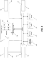
- FIG. 1 illustrates a control system for a vehicle such as a four-wheeled car or truck.
- An engine control unit 101 (“ECU") analyzes information such as vehicle performance variables and engine actuator settings and controls one or more vehicle/engine operations based on the received data.
- the ECU 101 includes a processor 103 and one or more non-transitory, computer-readable memory modules.
- the ECU 101 includes a random access memory (“RAM”) module 105 and a read-only memory (“ROM”) module 107.
- the ECU 101 also includes an input/output interface 109 that transmits and receives data over a controller area network (“CAN”) bus 111.
- CAN controller area network
- the ECU 101 can include multiple processors, additional computer-readable memory modules, multiple I/O interfaces, and/or additional components or modules (e.g., hardware, software, or a combination thereof).
- the processor 103 receives information from the I/O interface 111 and processes the information by executing instructions for one or more software modules (which may also be referred to as a "controller” or “controllers”) stored to a memory module of the ECU 101, such as the ROM 107. (which may also be referred to as a "controller” or “controllers”).
- the processor 103 stores information to and retrieves information from the RAM 105 (e.g., information received from other vehicle subsystems or sensors through the CAN bus 111 and information generated by modules executed by the processor 103).
- the non-transitory computer readable memory modules of the ECU 101 include volatile memory, non-volatile memory, or a combination thereof and, in various constructions, may also store operating system software, applications/instructions data, and combinations thereof.
- a braking sub-system 113 receives vehicle data and controls the braking pressure applied to each wheel of the vehicle (either symmetrically or asymmetrically).
- a steering sub-system 115 controls the steering angle applied to the front wheels of the vehicle based on the steering wheel position and other vehicle performance information.
- a drivetrain sub-system 117 controls the torque distribution applied to the wheels of the vehicle.
- Each of these vehicle sub-systems is connected to the CAN bus 111 and is capable of exchanging information with other devices connected to the CAN bus 111.
- a number of vehicle sensors are also attached to the CAN bus 111. These vehicle sensors monitor various vehicle performance characteristics and provide information to other devices on the CAN bus 111.
- One such vehicle sensor is the transmission output speed sensor (“TOSS" sensor) 119.
- the TOSS sensor monitors the output speed of the transmission and, in combination with other information such as, for example, vehicle differential settings and data from the drivetrain sub-system 117, provides information that can be used to determine the wheel speed of each individual wheel of the vehicle.
- TOSS algorithms that are used to provide individual wheel speeds are known by those skilled in the art.
- a series of wheel speed sensors 121, 123, 125, and 127 each coupled to an individual wheel 131, 133, 135, and 137, respectively.
- Each wheel speed sensor monitors the speed of an individual wheel and provides information indicative of the wheel speed to the CAN bus 111.
- the vehicle sub-systems use the wheel speed information for each individual wheel to modify vehicle performance.
- the engine control unit 101 may determine that unstable driving conditions are present and activate an electronic stability control ("ESC") program to distribute braking and torque to the wheels in a way that restores stability to the vehicle.
- ESC electronic stability control
- wheel speed information is not available directly from sensors coupled each of the four vehicle wheels.
- one of the four wheel speed sensors e.g., wheel speed sensor 121 corresponding to the rear left wheel 131 of the vehicle
- one of the four wheel speed sensors e.g., wheel speed sensor 121 corresponding to the rear left wheel 131 of the vehicle
- the ECU 101 estimates a wheel speed for the fourth wheel 133 based on wheel speed sensor readings for the other three wheels 133, 135, and 137.
- the ECU 101 of FIG. 1 is configured to perform three concurrent estimation calculations to determine an estimated wheel speed of the fourth vehicle wheel 131 based on the wheel speed sensor readings for the other three wheels 133, 135, and 137.
- the ESC program can operate based an estimated speed value for the fourth wheel calculated by any of equations (1), (2), or (3) above or an average of the three estimated values.
- the TOSS sensor 119 provides information that can be used to calculate a wheel speed for each individual wheel (including the fourth, sensorless wheel) based on the output of the vehicle transmission.
- the ESC program can use a wheel speed value calculated based on information from the TOSS sensor 119.
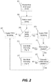
- FIG. 2 illustrates a method of monitoring a speed value for the fourth wheel 131 calculated based on information from the TOSS sensor 119 and validating the calculated speed value based on the wheel speed values estimated based on the measured wheel speeds of the other four vehicle wheels 133, 135, and 137.
- the ECU 101 receives wheel speed sensor values from each of the three existing/operational wheel speed sensors 123, 125, and 127 (step 201).
- the ECU 101 analyzes the signal quality from these sensors to determine whether they provide a reliable indication of measured wheel speeds (step 203). If the signal quality is unacceptable (step 205), the ECU 101 disables the TOSS monitoring mechanism described below (step 207). However, if the signal quality is adequate, the ECU 101 enables TOSS monitoring (step 209).
- the ECU 101 implements quick-mode monitoring to validate the estimated wheel speed based on TOSS output (step 213). However, if an unstable (or dynamic) driving situation is detected (step 211), the ECU 101 utilizes slow-mode TOSS monitoring (step 217). In some constructions, the ECU 101 determines that an unstable/dynamic driving condition is present when the ESC program (or other vehicle stability program) has been activated. Furthermore, in some constrictions, the ECU 101 may determine that the driving conditions are so unstable that no accurate validation of the wheel speed calculation can be performed (step 215). In such conditions, the ECU 101 disables TOSS monitoring (step 207) until driving conditions stabilize.
- FIG. 3 illustrates the quick-mode monitoring of the wheel speed calculation based on the output of the TOSS sensor 119.
- the quick mode operates under the assumption that, during more stable driving conditions, the wheel speed calculated based on the output of the TOSS sensor 119 can be validated more quickly and with greater sensitivity than when operating under unstable/dynamic driving conditions.
- the ECU 101 begins by calculating three estimated values for the speed of the fourth wheel based on equations (1), (2), and (3) described above (step 301). The ECU 101 then calculates a deviation value for each estimated wheel speed value as compared to the wheel speed value calculated based on the TOSS sensor 119 (step 303) - resulting in a total of three deviation values (one for each wheel speed estimation).
- the ECU 101 compares each of the three deviation values to a "quick mode" deviation threshold (step 305).
- the ECU 101 tracks the amount of time that at least two deviation values exceed the "quick mode” deviation threshold (step 309) and if the deviation continues for a defined "quick mode” time threshold (step 313), the ECU 101 determines that a fault condition exists and the wheel speed calculation for the fourth (sensorless) wheel cannot be relied upon (step 313). If at any time, fewer than two deviation values exceed the "quick mode" deviation threshold (step 305), the ECU 101 resets the time counter (step 307).
- FIG. 4 illustrates the slow-mode monitoring of the wheel speed calculation based on the output of the TOSS sensor 119.
- slow-mode monitoring is used by the ECU 101 during unstable/dynamic driving conditions based on the assumption that deviations due to external factors are more likely to occur during unstable/dynamic driving conditions and, therefore, deviations must be detected for longer time periods with less sensitivity.
- “Slow-mode” monitoring begins by calculating the three estimated values for the speed of the fourth wheel based on equations (1), (2), and (3) described above (step 401).
- the ECU 101 then calculates a deviation value for each estimated wheel speed value according to equation (4) above (step 403) - resulting in a total of three deviation values (one for each wheel speed estimation).
- the ECU 101 compares each deviation value to a "slow mode” deviation threshold (step 405) and tracks the amount of time that all three deviation values exceed a "slow mode” deviation threshold (step 409). Once at least one of the deviation values falls below the "slow mode” deviation threshold, the ECU 101 resets the timer (step 407). However, if the timer reaches a "slow mode" time threshold (step 411), the ECU 101 determines that a fault condition exists and the wheel speed calculation for the fourth (sensorless) wheel cannot be relied upon (step 413).
- the “slow mode” montoring is similar to the "quick mode” montoring with a few key distinctions.
- the "slow mode” time threshold is longer than the “quick mode” time threshold. Therefore, during “slow mode” monitoring a deviation must exist for a longer period of time before the ECU 101 declares a fault condition.
- the "slow mode” deviation threshold is higher than the "quick mode” deviation threshold. As such, greater deviations between the estimated wheel speed values and the TOSS-based, calculated value before the ECU 101 declares a fault condition.
- the invention provides, among other things, systems and methods to monitor and validate a calculated wheel speed of a specific wheel of a vehicle based on deviations between the calculated wheel speed and measured wheel speeds of the other vehicle wheels. It is noted that, although the examples described above all relate to estimating a wheel speed value for the rear left wheel, the methods and systems described herein can be applied to estimate and validate the wheel speed for any vehicle wheel. Furthermore, although the examples above describe three specific equations for using measured wheel speed values for three wheels to calculate an estimated wheel speed value for the fourth wheel, other constructions of this invention can utilized different estimation mechanism and can utilize more or fewer than three estimation values.
Landscapes
- Engineering & Computer Science (AREA)
- Mechanical Engineering (AREA)
- Automation & Control Theory (AREA)
- Physics & Mathematics (AREA)
- Transportation (AREA)
- General Physics & Mathematics (AREA)
- Mathematical Physics (AREA)
- Human Computer Interaction (AREA)
- Regulating Braking Force (AREA)
- Control Of Driving Devices And Active Controlling Of Vehicle (AREA)
- Valves And Accessory Devices For Braking Systems (AREA)
- Control Of Transmission Device (AREA)
Applications Claiming Priority (3)
| Application Number | Priority Date | Filing Date | Title |
|---|---|---|---|
| US201261746205P | 2012-12-27 | 2012-12-27 | |
| US13/906,908 US9218695B2 (en) | 2012-12-27 | 2013-05-31 | System and method for monitoring an estimated wheel speed of a vehicle using a transmission output shaft sensor |
| PCT/US2013/075042 WO2014105465A1 (en) | 2012-12-27 | 2013-12-13 | System and method for monitoring an estimated wheel speed of a vehicle using a transmission output shaft sensor |
Publications (2)
| Publication Number | Publication Date |
|---|---|
| EP2938507A1 EP2938507A1 (en) | 2015-11-04 |
| EP2938507B1 true EP2938507B1 (en) | 2018-04-25 |
Family
ID=51018131
Family Applications (1)
| Application Number | Title | Priority Date | Filing Date |
|---|---|---|---|
| EP13821239.4A Not-in-force EP2938507B1 (en) | 2012-12-27 | 2013-12-13 | System and method for monitoring an estimated wheel speed of a vehicle using a transmission output shaft sensor |
Country Status (5)
| Country | Link |
|---|---|
| US (1) | US9218695B2 (enExample) |
| EP (1) | EP2938507B1 (enExample) |
| JP (1) | JP6235609B2 (enExample) |
| CN (1) | CN104903129B (enExample) |
| WO (1) | WO2014105465A1 (enExample) |
Families Citing this family (13)
| Publication number | Priority date | Publication date | Assignee | Title |
|---|---|---|---|---|
| US10266017B2 (en) * | 2015-02-19 | 2019-04-23 | Dana Italia S.R.L. | Integration of sensor network and method of operation into a CTIS framework |
| WO2017010476A1 (ja) * | 2015-07-16 | 2017-01-19 | 昭和電工株式会社 | 二次電池用黒鉛含有炭素粉の製造方法及び電池電極用炭素材料 |
| KR101745157B1 (ko) * | 2015-10-26 | 2017-06-08 | 현대자동차주식회사 | 차량용 주행 제어방법 |
| US10486668B2 (en) * | 2017-08-17 | 2019-11-26 | Robert Bosch Gmbh | Systems and methods for redundant wheel speed sensing |
| CN109739078A (zh) * | 2018-12-28 | 2019-05-10 | 芜湖伯特利电子控制系统有限公司 | 一种轮速信号处理冗余方法 |
| CN111381070B (zh) * | 2018-12-29 | 2021-02-23 | 比亚迪股份有限公司 | 一种车辆及其车速计算方法与装置 |
| CN110173562A (zh) * | 2019-04-10 | 2019-08-27 | 东风商用车有限公司 | 一种amt输出轴转速传感器的使用方法 |
| US11326692B2 (en) | 2019-08-08 | 2022-05-10 | Sigma Powertrain, Inc. | Rotational control assembly for a vehicle transmission |
| CN113156156B (zh) * | 2021-03-31 | 2022-09-30 | 中车青岛四方车辆研究所有限公司 | 一种列车用多速度传感器系统速度处理方法 |
| US12054161B2 (en) * | 2022-03-09 | 2024-08-06 | GM Global Technology Operations LLC | Traction motor based wheel speed recovery |
| CN114734975B (zh) * | 2022-04-28 | 2023-05-09 | 清智汽车科技(苏州)有限公司 | 同轴车轮速传感器接线识别方法和装置 |
| CN119058634B (zh) * | 2024-08-21 | 2026-02-27 | 中国第一汽车股份有限公司 | 基于估算轮速的车辆控制方法和装置、车辆及存储介质 |
| CN121799355A (zh) * | 2026-03-11 | 2026-04-07 | 成都赛力斯科技有限公司 | 车辆控制方法、装置和车辆 |
Citations (2)
| Publication number | Priority date | Publication date | Assignee | Title |
|---|---|---|---|---|
| JPH07333239A (ja) * | 1994-06-09 | 1995-12-22 | Toyota Motor Corp | 車両のアンチスキッド制御装置 |
| US20120226469A1 (en) * | 2011-03-03 | 2012-09-06 | Robert Bosch Gmbh | Wheel speed estimation using a drivetrain model |
Family Cites Families (24)
| Publication number | Priority date | Publication date | Assignee | Title |
|---|---|---|---|---|
| US4260942A (en) | 1978-04-17 | 1981-04-07 | Trw Inc. | Failure detection and correction system for redundant control elements |
| JPH0790757B2 (ja) | 1986-08-28 | 1995-10-04 | 曙ブレーキ工業株式会社 | 車輪回転センサの故障検出装置 |
| JP2649712B2 (ja) | 1988-10-22 | 1997-09-03 | 住友電気工業株式会社 | アンチロック制御装置 |
| DE4122484A1 (de) | 1991-07-06 | 1993-01-07 | Teves Gmbh Alfred | Schaltungsanordnung zur erkennung von radsensordefekten |
| US5343396A (en) * | 1992-04-29 | 1994-08-30 | Youngblood Richard J | Sensor malfunction detection |
| JPH07205675A (ja) | 1994-01-26 | 1995-08-08 | Honda Motor Co Ltd | アンチロックブレーキ制御装置付車両における駆動状態切換制御方法 |
| US5431241A (en) * | 1994-05-31 | 1995-07-11 | Zexel-Gleason Usa, Inc. | Hybrid traction control system |
| US5642280A (en) | 1995-02-03 | 1997-06-24 | Kelsey-Hayes Company | Method and system for determining and compensating for a faulty wheel speed input signal in a vehicle control system |
| JP3624446B2 (ja) * | 1995-02-17 | 2005-03-02 | 日産自動車株式会社 | タイヤ内圧低下検出装置 |
| JPH08318836A (ja) | 1995-05-26 | 1996-12-03 | Mazda Motor Corp | 車両の制御装置 |
| DE19610864B4 (de) | 1996-03-20 | 2005-03-03 | Robert Bosch Gmbh | Verfahren und Vorrichtung zur Bestimmung der Raddrehgeschwindigkeit |
| JP3735939B2 (ja) * | 1996-04-25 | 2006-01-18 | 株式会社デンソー | 車両用ブレーキ装置 |
| DE10061502A1 (de) | 1999-12-08 | 2001-06-13 | Bosch Gmbh Robert | Verfahren und Vorrichtung zum Ermitteln einer Geschwindigkeitsgröße mindestens eines angetriebenen Rades eines Kraftfahrzeugs |
| US6285280B1 (en) * | 2000-06-26 | 2001-09-04 | Robert Bosch Corporation | Method for detecting a deflated tire on a vehicle |
| US6591937B2 (en) * | 2001-12-05 | 2003-07-15 | Delphi Technologies, Inc. | Adaptive variable effort power steering system |
| US7792617B2 (en) * | 2006-05-08 | 2010-09-07 | Ford Global Technologies | Wheel speed sensing system for electronic stability control |
| US7569948B2 (en) | 2006-09-26 | 2009-08-04 | Gm Global Technology Operations, Inc. | Method and system to prevent false speed display during high engine speed operation |
| JP4965396B2 (ja) * | 2007-09-06 | 2012-07-04 | トヨタ自動車株式会社 | 車両制御装置 |
| US8027771B2 (en) | 2007-09-13 | 2011-09-27 | GM Global Technology Operations LLC | Method and apparatus to monitor an output speed sensor during operation of an electro-mechanical transmission |
| FR2923436B1 (fr) | 2007-11-09 | 2010-04-09 | Michelin Soc Tech | Systeme de controle du comportement d'un vehicule comportant une determination de sa vitesse par rapport au sol |
| JP2009128239A (ja) * | 2007-11-26 | 2009-06-11 | Mitsubishi Fuso Truck & Bus Corp | 車速センサの故障判定装置及び故障判定方法 |
| US8771140B2 (en) | 2008-12-22 | 2014-07-08 | Caterpillar Inc. | Machine control system utilizing inertial yaw sensor |
| US8620555B2 (en) | 2009-11-30 | 2013-12-31 | GM Global Technology Operations LLC | Wheel slip determination for vehicles |
| US8437884B2 (en) | 2010-07-28 | 2013-05-07 | GM Global Technology Operations LLC | System and method for detecting vehicle motion |
-
2013
- 2013-05-31 US US13/906,908 patent/US9218695B2/en not_active Expired - Fee Related
- 2013-12-13 JP JP2015550449A patent/JP6235609B2/ja not_active Expired - Fee Related
- 2013-12-13 WO PCT/US2013/075042 patent/WO2014105465A1/en not_active Ceased
- 2013-12-13 CN CN201380067956.7A patent/CN104903129B/zh not_active Expired - Fee Related
- 2013-12-13 EP EP13821239.4A patent/EP2938507B1/en not_active Not-in-force
Patent Citations (2)
| Publication number | Priority date | Publication date | Assignee | Title |
|---|---|---|---|---|
| JPH07333239A (ja) * | 1994-06-09 | 1995-12-22 | Toyota Motor Corp | 車両のアンチスキッド制御装置 |
| US20120226469A1 (en) * | 2011-03-03 | 2012-09-06 | Robert Bosch Gmbh | Wheel speed estimation using a drivetrain model |
Also Published As
| Publication number | Publication date |
|---|---|
| JP6235609B2 (ja) | 2017-11-22 |
| CN104903129B (zh) | 2017-07-04 |
| US20140188352A1 (en) | 2014-07-03 |
| EP2938507A1 (en) | 2015-11-04 |
| JP2016510399A (ja) | 2016-04-07 |
| WO2014105465A1 (en) | 2014-07-03 |
| US9218695B2 (en) | 2015-12-22 |
| CN104903129A (zh) | 2015-09-09 |
Similar Documents
| Publication | Publication Date | Title |
|---|---|---|
| EP2938507B1 (en) | System and method for monitoring an estimated wheel speed of a vehicle using a transmission output shaft sensor | |
| CN107628036B (zh) | 传感器故障的检测和重建 | |
| EP2738059B1 (en) | Method and apparatus for vehicle sway detection and reduction | |
| US9330061B2 (en) | Determination of steering angle for a motor vehicle | |
| US9969425B2 (en) | Rear wheel steering control | |
| US9988043B2 (en) | Methods and systems for determining a vehicle spin-out condition | |
| JP6056954B2 (ja) | 車両の走行運動制御装置 | |
| US9878738B2 (en) | Non-linear compensation controller for active steering system in a vehicle | |
| US20090218881A1 (en) | Fluid pressure control device | |
| KR102063959B1 (ko) | 구배도를 이용한 트레일러 모드 판단 장치 및 방법 | |
| GB2574257A (en) | Vehicle dynamics estimation method and apparatus | |
| KR101514132B1 (ko) | 사륜 구동 차량의 조향각 추정 방법 | |
| CN108688668B (zh) | 用于车辆侧向力控制的方法和系统 | |
| JPWO2014136188A1 (ja) | 車両の基準運動状態量の演算方法 | |
| EP3426531B1 (en) | A method of adjusting an estimated value of the height of the gravity center of a vehicle | |
| KR102120204B1 (ko) | 요 레이트 센서의 오프셋 보정 장치 및 그 방법 | |
| EP4713230A1 (en) | System and method for detecting wheel slip | |
| KR20130101916A (ko) | 휠 횡하중을 이용한 차량 제어 장치 및 그 방법 | |
| CN118566537A (zh) | 车辆的加速度检测方法、装置及设备 | |
| CN121697735A (zh) | 用于监测车辆转向系统的方法及监测系统 | |
| KR20170047042A (ko) | 차량의 횡슬립각 추정장치 | |
| CN120024338A (zh) | 车速的估算方法、估算装置及车辆 | |
| KR100950927B1 (ko) | 차량 제어시스템의 센서 진단방법 | |
| CN119705383A (zh) | 稳定性控制方法、车辆及存储介质 | |
| JP2005300538A (ja) | システム、方法、車両、ecu、コンピュータ・プログラムおよびコンピュータ・プログラム製品 |
Legal Events
| Date | Code | Title | Description |
|---|---|---|---|
| PUAI | Public reference made under article 153(3) epc to a published international application that has entered the european phase |
Free format text: ORIGINAL CODE: 0009012 |
|
| 17P | Request for examination filed |
Effective date: 20150727 |
|
| AK | Designated contracting states |
Kind code of ref document: A1 Designated state(s): AL AT BE BG CH CY CZ DE DK EE ES FI FR GB GR HR HU IE IS IT LI LT LU LV MC MK MT NL NO PL PT RO RS SE SI SK SM TR |
|
| AX | Request for extension of the european patent |
Extension state: BA ME |
|
| RIN1 | Information on inventor provided before grant (corrected) |
Inventor name: YU, ZERONG |
|
| DAX | Request for extension of the european patent (deleted) | ||
| GRAP | Despatch of communication of intention to grant a patent |
Free format text: ORIGINAL CODE: EPIDOSNIGR1 |
|
| STAA | Information on the status of an ep patent application or granted ep patent |
Free format text: STATUS: GRANT OF PATENT IS INTENDED |
|
| INTG | Intention to grant announced |
Effective date: 20171123 |
|
| GRAA | (expected) grant |
Free format text: ORIGINAL CODE: 0009210 |
|
| GRAS | Grant fee paid |
Free format text: ORIGINAL CODE: EPIDOSNIGR3 |
|
| STAA | Information on the status of an ep patent application or granted ep patent |
Free format text: STATUS: THE PATENT HAS BEEN GRANTED |
|
| AK | Designated contracting states |
Kind code of ref document: B1 Designated state(s): AL AT BE BG CH CY CZ DE DK EE ES FI FR GB GR HR HU IE IS IT LI LT LU LV MC MK MT NL NO PL PT RO RS SE SI SK SM TR |
|
| REG | Reference to a national code |
Ref country code: GB Ref legal event code: FG4D |
|
| REG | Reference to a national code |
Ref country code: CH Ref legal event code: EP |
|
| REG | Reference to a national code |
Ref country code: AT Ref legal event code: REF Ref document number: 992472 Country of ref document: AT Kind code of ref document: T Effective date: 20180515 |
|
| REG | Reference to a national code |
Ref country code: IE Ref legal event code: FG4D |
|
| REG | Reference to a national code |
Ref country code: DE Ref legal event code: R096 Ref document number: 602013036619 Country of ref document: DE |
|
| REG | Reference to a national code |
Ref country code: NL Ref legal event code: MP Effective date: 20180425 |
|
| REG | Reference to a national code |
Ref country code: LT Ref legal event code: MG4D |
|
| PG25 | Lapsed in a contracting state [announced via postgrant information from national office to epo] |
Ref country code: NL Free format text: LAPSE BECAUSE OF FAILURE TO SUBMIT A TRANSLATION OF THE DESCRIPTION OR TO PAY THE FEE WITHIN THE PRESCRIBED TIME-LIMIT Effective date: 20180425 |
|
| PG25 | Lapsed in a contracting state [announced via postgrant information from national office to epo] |
Ref country code: FI Free format text: LAPSE BECAUSE OF FAILURE TO SUBMIT A TRANSLATION OF THE DESCRIPTION OR TO PAY THE FEE WITHIN THE PRESCRIBED TIME-LIMIT Effective date: 20180425 Ref country code: BG Free format text: LAPSE BECAUSE OF FAILURE TO SUBMIT A TRANSLATION OF THE DESCRIPTION OR TO PAY THE FEE WITHIN THE PRESCRIBED TIME-LIMIT Effective date: 20180725 Ref country code: NO Free format text: LAPSE BECAUSE OF FAILURE TO SUBMIT A TRANSLATION OF THE DESCRIPTION OR TO PAY THE FEE WITHIN THE PRESCRIBED TIME-LIMIT Effective date: 20180725 Ref country code: SE Free format text: LAPSE BECAUSE OF FAILURE TO SUBMIT A TRANSLATION OF THE DESCRIPTION OR TO PAY THE FEE WITHIN THE PRESCRIBED TIME-LIMIT Effective date: 20180425 Ref country code: LT Free format text: LAPSE BECAUSE OF FAILURE TO SUBMIT A TRANSLATION OF THE DESCRIPTION OR TO PAY THE FEE WITHIN THE PRESCRIBED TIME-LIMIT Effective date: 20180425 Ref country code: PL Free format text: LAPSE BECAUSE OF FAILURE TO SUBMIT A TRANSLATION OF THE DESCRIPTION OR TO PAY THE FEE WITHIN THE PRESCRIBED TIME-LIMIT Effective date: 20180425 Ref country code: ES Free format text: LAPSE BECAUSE OF FAILURE TO SUBMIT A TRANSLATION OF THE DESCRIPTION OR TO PAY THE FEE WITHIN THE PRESCRIBED TIME-LIMIT Effective date: 20180425 |
|
| PG25 | Lapsed in a contracting state [announced via postgrant information from national office to epo] |
Ref country code: RS Free format text: LAPSE BECAUSE OF FAILURE TO SUBMIT A TRANSLATION OF THE DESCRIPTION OR TO PAY THE FEE WITHIN THE PRESCRIBED TIME-LIMIT Effective date: 20180425 Ref country code: HR Free format text: LAPSE BECAUSE OF FAILURE TO SUBMIT A TRANSLATION OF THE DESCRIPTION OR TO PAY THE FEE WITHIN THE PRESCRIBED TIME-LIMIT Effective date: 20180425 Ref country code: GR Free format text: LAPSE BECAUSE OF FAILURE TO SUBMIT A TRANSLATION OF THE DESCRIPTION OR TO PAY THE FEE WITHIN THE PRESCRIBED TIME-LIMIT Effective date: 20180726 Ref country code: LV Free format text: LAPSE BECAUSE OF FAILURE TO SUBMIT A TRANSLATION OF THE DESCRIPTION OR TO PAY THE FEE WITHIN THE PRESCRIBED TIME-LIMIT Effective date: 20180425 |
|
| REG | Reference to a national code |
Ref country code: AT Ref legal event code: MK05 Ref document number: 992472 Country of ref document: AT Kind code of ref document: T Effective date: 20180425 |
|
| PG25 | Lapsed in a contracting state [announced via postgrant information from national office to epo] |
Ref country code: PT Free format text: LAPSE BECAUSE OF FAILURE TO SUBMIT A TRANSLATION OF THE DESCRIPTION OR TO PAY THE FEE WITHIN THE PRESCRIBED TIME-LIMIT Effective date: 20180827 |
|
| REG | Reference to a national code |
Ref country code: DE Ref legal event code: R097 Ref document number: 602013036619 Country of ref document: DE |
|
| PG25 | Lapsed in a contracting state [announced via postgrant information from national office to epo] |
Ref country code: SK Free format text: LAPSE BECAUSE OF FAILURE TO SUBMIT A TRANSLATION OF THE DESCRIPTION OR TO PAY THE FEE WITHIN THE PRESCRIBED TIME-LIMIT Effective date: 20180425 Ref country code: RO Free format text: LAPSE BECAUSE OF FAILURE TO SUBMIT A TRANSLATION OF THE DESCRIPTION OR TO PAY THE FEE WITHIN THE PRESCRIBED TIME-LIMIT Effective date: 20180425 Ref country code: EE Free format text: LAPSE BECAUSE OF FAILURE TO SUBMIT A TRANSLATION OF THE DESCRIPTION OR TO PAY THE FEE WITHIN THE PRESCRIBED TIME-LIMIT Effective date: 20180425 Ref country code: CZ Free format text: LAPSE BECAUSE OF FAILURE TO SUBMIT A TRANSLATION OF THE DESCRIPTION OR TO PAY THE FEE WITHIN THE PRESCRIBED TIME-LIMIT Effective date: 20180425 Ref country code: AT Free format text: LAPSE BECAUSE OF FAILURE TO SUBMIT A TRANSLATION OF THE DESCRIPTION OR TO PAY THE FEE WITHIN THE PRESCRIBED TIME-LIMIT Effective date: 20180425 Ref country code: DK Free format text: LAPSE BECAUSE OF FAILURE TO SUBMIT A TRANSLATION OF THE DESCRIPTION OR TO PAY THE FEE WITHIN THE PRESCRIBED TIME-LIMIT Effective date: 20180425 |
|
| PG25 | Lapsed in a contracting state [announced via postgrant information from national office to epo] |
Ref country code: SM Free format text: LAPSE BECAUSE OF FAILURE TO SUBMIT A TRANSLATION OF THE DESCRIPTION OR TO PAY THE FEE WITHIN THE PRESCRIBED TIME-LIMIT Effective date: 20180425 Ref country code: IT Free format text: LAPSE BECAUSE OF FAILURE TO SUBMIT A TRANSLATION OF THE DESCRIPTION OR TO PAY THE FEE WITHIN THE PRESCRIBED TIME-LIMIT Effective date: 20180425 |
|
| PLBE | No opposition filed within time limit |
Free format text: ORIGINAL CODE: 0009261 |
|
| STAA | Information on the status of an ep patent application or granted ep patent |
Free format text: STATUS: NO OPPOSITION FILED WITHIN TIME LIMIT |
|
| 26N | No opposition filed |
Effective date: 20190128 |
|
| PG25 | Lapsed in a contracting state [announced via postgrant information from national office to epo] |
Ref country code: SI Free format text: LAPSE BECAUSE OF FAILURE TO SUBMIT A TRANSLATION OF THE DESCRIPTION OR TO PAY THE FEE WITHIN THE PRESCRIBED TIME-LIMIT Effective date: 20180425 |
|
| REG | Reference to a national code |
Ref country code: CH Ref legal event code: PL |
|
| PG25 | Lapsed in a contracting state [announced via postgrant information from national office to epo] |
Ref country code: MC Free format text: LAPSE BECAUSE OF FAILURE TO SUBMIT A TRANSLATION OF THE DESCRIPTION OR TO PAY THE FEE WITHIN THE PRESCRIBED TIME-LIMIT Effective date: 20180425 Ref country code: LU Free format text: LAPSE BECAUSE OF NON-PAYMENT OF DUE FEES Effective date: 20181213 |
|
| REG | Reference to a national code |
Ref country code: IE Ref legal event code: MM4A |
|
| REG | Reference to a national code |
Ref country code: BE Ref legal event code: MM Effective date: 20181231 |
|
| PG25 | Lapsed in a contracting state [announced via postgrant information from national office to epo] |
Ref country code: IE Free format text: LAPSE BECAUSE OF NON-PAYMENT OF DUE FEES Effective date: 20181213 |
|
| PG25 | Lapsed in a contracting state [announced via postgrant information from national office to epo] |
Ref country code: AL Free format text: LAPSE BECAUSE OF FAILURE TO SUBMIT A TRANSLATION OF THE DESCRIPTION OR TO PAY THE FEE WITHIN THE PRESCRIBED TIME-LIMIT Effective date: 20180425 Ref country code: BE Free format text: LAPSE BECAUSE OF NON-PAYMENT OF DUE FEES Effective date: 20181231 |
|
| PG25 | Lapsed in a contracting state [announced via postgrant information from national office to epo] |
Ref country code: CH Free format text: LAPSE BECAUSE OF NON-PAYMENT OF DUE FEES Effective date: 20181231 Ref country code: LI Free format text: LAPSE BECAUSE OF NON-PAYMENT OF DUE FEES Effective date: 20181231 |
|
| PG25 | Lapsed in a contracting state [announced via postgrant information from national office to epo] |
Ref country code: MT Free format text: LAPSE BECAUSE OF NON-PAYMENT OF DUE FEES Effective date: 20181213 |
|
| PGFP | Annual fee paid to national office [announced via postgrant information from national office to epo] |
Ref country code: FR Payment date: 20191219 Year of fee payment: 7 |
|
| PG25 | Lapsed in a contracting state [announced via postgrant information from national office to epo] |
Ref country code: TR Free format text: LAPSE BECAUSE OF FAILURE TO SUBMIT A TRANSLATION OF THE DESCRIPTION OR TO PAY THE FEE WITHIN THE PRESCRIBED TIME-LIMIT Effective date: 20180425 |
|
| PGFP | Annual fee paid to national office [announced via postgrant information from national office to epo] |
Ref country code: GB Payment date: 20191220 Year of fee payment: 7 |
|
| PG25 | Lapsed in a contracting state [announced via postgrant information from national office to epo] |
Ref country code: MK Free format text: LAPSE BECAUSE OF NON-PAYMENT OF DUE FEES Effective date: 20180425 Ref country code: HU Free format text: LAPSE BECAUSE OF FAILURE TO SUBMIT A TRANSLATION OF THE DESCRIPTION OR TO PAY THE FEE WITHIN THE PRESCRIBED TIME-LIMIT; INVALID AB INITIO Effective date: 20131213 Ref country code: CY Free format text: LAPSE BECAUSE OF FAILURE TO SUBMIT A TRANSLATION OF THE DESCRIPTION OR TO PAY THE FEE WITHIN THE PRESCRIBED TIME-LIMIT Effective date: 20180425 |
|
| PG25 | Lapsed in a contracting state [announced via postgrant information from national office to epo] |
Ref country code: IS Free format text: LAPSE BECAUSE OF FAILURE TO SUBMIT A TRANSLATION OF THE DESCRIPTION OR TO PAY THE FEE WITHIN THE PRESCRIBED TIME-LIMIT Effective date: 20180825 |
|
| GBPC | Gb: european patent ceased through non-payment of renewal fee |
Effective date: 20201213 |
|
| PG25 | Lapsed in a contracting state [announced via postgrant information from national office to epo] |
Ref country code: FR Free format text: LAPSE BECAUSE OF NON-PAYMENT OF DUE FEES Effective date: 20201231 |
|
| PG25 | Lapsed in a contracting state [announced via postgrant information from national office to epo] |
Ref country code: GB Free format text: LAPSE BECAUSE OF NON-PAYMENT OF DUE FEES Effective date: 20201213 |
|
| PGFP | Annual fee paid to national office [announced via postgrant information from national office to epo] |
Ref country code: DE Payment date: 20230223 Year of fee payment: 10 |
|
| REG | Reference to a national code |
Ref country code: DE Ref legal event code: R119 Ref document number: 602013036619 Country of ref document: DE |
|
| PG25 | Lapsed in a contracting state [announced via postgrant information from national office to epo] |
Ref country code: DE Free format text: LAPSE BECAUSE OF NON-PAYMENT OF DUE FEES Effective date: 20240702 |
|
| PG25 | Lapsed in a contracting state [announced via postgrant information from national office to epo] |
Ref country code: DE Free format text: LAPSE BECAUSE OF NON-PAYMENT OF DUE FEES Effective date: 20240702 |