EP2937540B1 - Multi-stage supercharging system, and device and method for controlling same - Google Patents
Multi-stage supercharging system, and device and method for controlling same Download PDFInfo
- Publication number
- EP2937540B1 EP2937540B1 EP13873977.6A EP13873977A EP2937540B1 EP 2937540 B1 EP2937540 B1 EP 2937540B1 EP 13873977 A EP13873977 A EP 13873977A EP 2937540 B1 EP2937540 B1 EP 2937540B1
- Authority
- EP
- European Patent Office
- Prior art keywords
- supercharger
- water vapor
- air
- pressure
- partial pressure
- Prior art date
- Legal status (The legal status is an assumption and is not a legal conclusion. Google has not performed a legal analysis and makes no representation as to the accuracy of the status listed.)
- Active
Links
- 238000000034 method Methods 0.000 title claims description 17
- XLYOFNOQVPJJNP-UHFFFAOYSA-N water Chemical compound O XLYOFNOQVPJJNP-UHFFFAOYSA-N 0.000 claims description 138
- 230000014509 gene expression Effects 0.000 claims description 33
- 238000001816 cooling Methods 0.000 claims description 28
- 238000002485 combustion reaction Methods 0.000 claims description 13
- 239000003595 mist Substances 0.000 description 16
- 238000010586 diagram Methods 0.000 description 6
- 230000003247 decreasing effect Effects 0.000 description 3
- 230000006835 compression Effects 0.000 description 2
- 238000007906 compression Methods 0.000 description 2
- 230000000694 effects Effects 0.000 description 2
- 239000002699 waste material Substances 0.000 description 1
Images


Classifications
-
- F—MECHANICAL ENGINEERING; LIGHTING; HEATING; WEAPONS; BLASTING
- F02—COMBUSTION ENGINES; HOT-GAS OR COMBUSTION-PRODUCT ENGINE PLANTS
- F02B—INTERNAL-COMBUSTION PISTON ENGINES; COMBUSTION ENGINES IN GENERAL
- F02B29/00—Engines characterised by provision for charging or scavenging not provided for in groups F02B25/00, F02B27/00 or F02B33/00 - F02B39/00; Details thereof
- F02B29/04—Cooling of air intake supply
- F02B29/0493—Controlling the air charge temperature
-
- F—MECHANICAL ENGINEERING; LIGHTING; HEATING; WEAPONS; BLASTING
- F02—COMBUSTION ENGINES; HOT-GAS OR COMBUSTION-PRODUCT ENGINE PLANTS
- F02B—INTERNAL-COMBUSTION PISTON ENGINES; COMBUSTION ENGINES IN GENERAL
- F02B29/00—Engines characterised by provision for charging or scavenging not provided for in groups F02B25/00, F02B27/00 or F02B33/00 - F02B39/00; Details thereof
- F02B29/04—Cooling of air intake supply
- F02B29/0406—Layout of the intake air cooling or coolant circuit
- F02B29/0412—Multiple heat exchangers arranged in parallel or in series
-
- F—MECHANICAL ENGINEERING; LIGHTING; HEATING; WEAPONS; BLASTING
- F02—COMBUSTION ENGINES; HOT-GAS OR COMBUSTION-PRODUCT ENGINE PLANTS
- F02B—INTERNAL-COMBUSTION PISTON ENGINES; COMBUSTION ENGINES IN GENERAL
- F02B37/00—Engines characterised by provision of pumps driven at least for part of the time by exhaust
- F02B37/013—Engines characterised by provision of pumps driven at least for part of the time by exhaust with exhaust-driven pumps arranged in series
-
- F—MECHANICAL ENGINEERING; LIGHTING; HEATING; WEAPONS; BLASTING
- F02—COMBUSTION ENGINES; HOT-GAS OR COMBUSTION-PRODUCT ENGINE PLANTS
- F02D—CONTROLLING COMBUSTION ENGINES
- F02D41/00—Electrical control of supply of combustible mixture or its constituents
- F02D41/0002—Controlling intake air
- F02D41/0007—Controlling intake air for control of turbo-charged or super-charged engines
-
- F—MECHANICAL ENGINEERING; LIGHTING; HEATING; WEAPONS; BLASTING
- F01—MACHINES OR ENGINES IN GENERAL; ENGINE PLANTS IN GENERAL; STEAM ENGINES
- F01P—COOLING OF MACHINES OR ENGINES IN GENERAL; COOLING OF INTERNAL-COMBUSTION ENGINES
- F01P2060/00—Cooling circuits using auxiliaries
- F01P2060/02—Intercooler
-
- F—MECHANICAL ENGINEERING; LIGHTING; HEATING; WEAPONS; BLASTING
- F02—COMBUSTION ENGINES; HOT-GAS OR COMBUSTION-PRODUCT ENGINE PLANTS
- F02D—CONTROLLING COMBUSTION ENGINES
- F02D2200/00—Input parameters for engine control
- F02D2200/02—Input parameters for engine control the parameters being related to the engine
- F02D2200/04—Engine intake system parameters
- F02D2200/0406—Intake manifold pressure
-
- F—MECHANICAL ENGINEERING; LIGHTING; HEATING; WEAPONS; BLASTING
- F02—COMBUSTION ENGINES; HOT-GAS OR COMBUSTION-PRODUCT ENGINE PLANTS
- F02D—CONTROLLING COMBUSTION ENGINES
- F02D2200/00—Input parameters for engine control
- F02D2200/02—Input parameters for engine control the parameters being related to the engine
- F02D2200/04—Engine intake system parameters
- F02D2200/0414—Air temperature
-
- F—MECHANICAL ENGINEERING; LIGHTING; HEATING; WEAPONS; BLASTING
- F02—COMBUSTION ENGINES; HOT-GAS OR COMBUSTION-PRODUCT ENGINE PLANTS
- F02D—CONTROLLING COMBUSTION ENGINES
- F02D2200/00—Input parameters for engine control
- F02D2200/02—Input parameters for engine control the parameters being related to the engine
- F02D2200/04—Engine intake system parameters
- F02D2200/0418—Air humidity
-
- Y—GENERAL TAGGING OF NEW TECHNOLOGICAL DEVELOPMENTS; GENERAL TAGGING OF CROSS-SECTIONAL TECHNOLOGIES SPANNING OVER SEVERAL SECTIONS OF THE IPC; TECHNICAL SUBJECTS COVERED BY FORMER USPC CROSS-REFERENCE ART COLLECTIONS [XRACs] AND DIGESTS
- Y02—TECHNOLOGIES OR APPLICATIONS FOR MITIGATION OR ADAPTATION AGAINST CLIMATE CHANGE
- Y02T—CLIMATE CHANGE MITIGATION TECHNOLOGIES RELATED TO TRANSPORTATION
- Y02T10/00—Road transport of goods or passengers
- Y02T10/10—Internal combustion engine [ICE] based vehicles
- Y02T10/12—Improving ICE efficiencies
Definitions
- the present invention relates to a multi-stage supercharging system and the device and method for controlling the multi-stage supercharging system.
- JP 2012-87737A discloses a double-stage supercharging system configured such that a cooler is interposed between a low-pressure turbocharger and a high-pressure turbocharger and that a flow of air compressed at the low-pressure turbocharger is cooled at the cooler and then, is supplied to the high-pressure turbocharger.
- WO 2009/002233A1 discloses a multi-stage supercharging system including a first turbocharger stage, a second turbocharger stage, a first heat exchanger that is arranged between the first and the second turbocharger stages for cooling a compressed air, and a first intake air bypass for modulating a flow of air through the first heat exchanger.
- the flow of the air through the first heat exchanger is modulated so that a second temperature T 2 at an outlet of the first heat exchanger is above a first dew-point temperature T dew1 .
- the present invention has been made in view of the above-described situation, and is intended to provide a multi-stage supercharging system capable of reducing generation of water mist in cooling of compressed air and to provide the device and method for controlling the multi-stage supercharging system.
- the present invention provides a control device of a multi-stage supercharging system with the features of claim 1, a multi-stage supercharging system including the control device of the invention, and a method for controlling a multi-stage supercharging system with the features of claim 4.
- a first aspect of the present invention thus provides a control device of a multi-stage supercharging system which includes a first supercharger of a low-pressure side, a cooling means that cools air discharged from the first supercharger, and a second supercharger of a high-pressure side that compresses the discharged air after cooling and which supplies, to an internal-combustion engine, air compressed in at least two stages.
- the control device includes an information acquisition means that acquires, as input information, the sucked air temperature, the sucked air humidity, the sucked air pressure, and the discharge pressure of the first supercharger, a water vapor partial pressure calculation means that calculates the water vapor partial pressure of the discharged air of the first supercharger by using the sucked air temperature, the sucked air humidity, the sucked air pressure, and the discharge pressure of the first supercharger as parameters, a target temperature setting means that sets, as a target temperature, a temperature at which the water vapor partial pressure calculated by the water vapor partial pressure calculation means reaches a saturated water vapor pressure, and a cooling control means that controls the cooling means such that the sucked air temperature of the second supercharger reaches equal to or higher than the target temperature.
- the sucked air temperature of the second supercharger may be simply increased.
- an increase in the temperature of the sucked air leads to lowering of the efficiency of the supercharger.
- it is preferred that a temperature increase is avoided, considering the efficiency.
- the water vapor partial pressure in the discharged air of the first supercharger is calculated, and then, the temperature at which such a water vapor partial pressure reaches the saturated water vapor partial pressure is obtained. Subsequently, such a temperature is set as the target temperature of the sucked air of the second supercharger. Since this target temperature indicates the minimum temperature at which no water mist is generated from the sucked air of the second supercharger, generation of water mist can be avoided, and lowering of the efficiency of the supercharger can be reduced as much as possible.
- the suction temperature of the second supercharger can be controlled within a suitable range, considering generation of water mist and the efficiency of the supercharger.
- the information acquisition means acquires, as the input information, the rotation speed or the air flow rate of the first supercharger
- the target temperature setting means uses the water vapor partial pressure calculated by the water vapor partial pressure calculation means and the sucked air temperature, the sucked air pressure, the discharge pressure, and the rotation speed or the air flow rate of the first supercharger to set, as the target temperature, such a sucked air temperature of the second supercharger that a condensed water amount contained in air sucked into the second supercharger reaches a predetermined allowable condensed water amount determined depending on the characteristic of the second supercharger.
- the temperature at which the condensed water amount contained in the sucked air of the second supercharger becomes coincident with the preset allowable condensed water amount is set as the target temperature.
- the target temperature of the sucked air of the second supercharger is decreased accordingly.
- the target temperature setting means may use, as an unknown value, a water vapor partial pressure in the sucked air of the second supercharger to set an expression indicating the condensed water amount contained in the sucked air of the second supercharger, obtain the water vapor partial pressure when the expression is equal to the allowable condensed water amount, and set, as the target temperature, a temperature at which the water vapor partial pressure reaches the saturated water vapor pressure, for example.
- a second aspect of the present invention provides a multi-stage supercharging system including a first supercharger of a low-pressure side, a cooling means that cools air discharged from the first supercharger, a second supercharger of a high-pressure side that compresses the discharged air after cooling, and the control device of the multi-stage supercharging system as described above. Air compressed in at least two stages is supplied to an internal-combustion engine.
- a third aspect of the present invention provides a method for controlling a multi-stage supercharging system which includes a first supercharger of a low-pressure side, a cooling means that cools air discharged from the first supercharger, and a second supercharger of a high-pressure side that compresses the discharged air after cooling and which supplies, to an internal-combustion engine, air compressed in at least two stages.
- the method includes an information acquiring step of acquiring, as input information, the sucked air temperature, the sucked air humidity, the sucked air pressure, and the discharge pressure of the first supercharger, a water vapor partial pressure calculating step of calculating the water vapor partial pressure of the discharged air of the first supercharger by using the sucked air temperature, the sucked air humidity, the sucked air pressure, and the discharge pressure of the first supercharger as parameters, a target temperature setting step of setting, as a target temperature, a temperature at which the water vapor partial pressure calculated at the water vapor partial pressure calculating step reaches a saturated water vapor pressure, and a cooling control step of controlling the cooling means such that the sucked air temperature of the second supercharger reaches equal to or higher than the target temperature.
- the rotation speed or the air flow rate of the first supercharger is acquired as the input information
- the water vapor partial pressure calculated at the water vapor partial pressure calculating step and the sucked air temperature, the sucked air pressure, the discharge pressure, and the rotation speed or the air flow rate of the first supercharger are used to set, as the target temperature, such a sucked air temperature of the second supercharger that a condensed water amount contained in air sucked into the second supercharger reaches a predetermined allowable condensed water amount determined depending on the characteristic of the second supercharger.
- a water vapor partial pressure in the sucked air of the second supercharger may be used as an unknown value to set an expression indicating the condensed water amount contained in the sucked air of the second supercharger, the water vapor partial pressure may be acquired when the expression is equal to the allowable condensed water amount, and a temperature at which the water vapor partial pressure reaches the saturated water vapor pressure may be set as the target temperature.
- a multi-stage supercharging system of an example serving to explain features of the present invention and the device and method for controlling such a multi-stage supercharging system will be described below with reference to drawings.
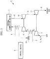
- Fig. 1 is a diagram schematically illustrating, as one example of the multi-stage supercharging system of the present embodiment, an example configuration of a double-stage supercharging system.
- a multi-stage supercharging system 1 includes, as main components, a first supercharger 2 of a low-pressure side, an intercooler (a cooling means) 3 that cools air discharged from the first supercharger 2, a second supercharger 4 of a high-pressure side compresses the discharged air after cooling, and a control device 5.
- Compressed air discharged from the second supercharger 4 is cooled by an intercooler 6, and then, is supplied to an internal-combustion engine 7.
- a high-pressure second turbine 10 and a low-pressure first turbine 11 are provided at an exhaust gas pipe 8 though which exhaust gas of the internal-combustion engine 7 is discharged, and are rotated by exhaust gas.
- the second turbine 10 is uniaxially connected to the second supercharger 4, and the first turbine 11 is uniaxially connected to the first supercharger 2.
- the rotational force of the second turbine 10 and the rotational force of the first turbine 11 are transmitted respectively to the second supercharger 4 and the first supercharger 2, thereby driving the second supercharger 4 and the first supercharger 2.
- the sucked air temperature T 1 (°C), the sucked air humidity H 1 (%), the sucked air pressure P 1 (kPa), and the discharge pressure P 2 (kPa) of the first supercharger 2 and the sucked air temperature T 2 (°C) of the second supercharger 4 are detected by sensors (not shown), and then, are output to the control device 5.
- the control device 5 controls the intercooler 3 such that the sucked air temperature T 2 of the second supercharger 4 reaches a proper temperature, considering, e.g., both of the soundness and efficiency of the second supercharger 4.
- Fig. 2 is a block diagram of the functions of the control device 5. As illustrated in Fig. 2 , the control device 5 includes an information acquisition section 21, a water vapor partial pressure calculation section 22, a target temperature setting section 23, and a valve opening degree control section (a cooling control means) 24.
- the control device 5 includes an information acquisition section 21, a water vapor partial pressure calculation section 22, a target temperature setting section 23, and a valve opening degree control section (a cooling control means) 24.
- the information acquisition section 21 acquires the sucked air temperature T 1 (°C), the sucked air humidity H 1 (%), the sucked air pressure P 1 (kPa), and the discharge pressure P 2 (kPa) of the first supercharger 2 and the sucked air temperature T 2 (°C) of the second supercharger 4, these parameters being detected by the sensors.
- the water vapor partial pressure calculation section 22 calculates, using the sucked air temperature T 1 (°C), the sucked air humidity H 1 (%), the sucked air pressure P 1 (kPa), and the discharge pressure P 2 (kPa) of the first supercharger 2 as parameters, the water vapor partial pressure P W2 (kPa) of air discharged from the first supercharger 2.
- the water vapor partial pressure P W1 (kPa) of air sucked into the first supercharger 2 is represented by the following function expression (1) using the sucked air temperature T 1 (°C) and the sucked air humidity H 1 (%) as parameters.
- P W 1 F X 1 T 1 , H 1
- the water vapor partial pressure P W1 (kPa) of air sucked into the first supercharger 2 can be obtained by multiplying a saturated water vapor pressure P W1_SAT (kPa) at the sucked air temperature T 1 (°C) by the sucked air humidity H 1 (%).
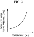
- the saturated water vapor pressure P W1_SAT (kPa) at the sucked air temperature T 1 (°C) can be, for example, obtained from a graph showing the relationship between a saturated water vapor pressure P W_SAT (kPa) and a temperature T (°C) as shown in Fig. 3 or an approximate expression for calculating these parameters.
- the water vapor partial pressure P W2 (kPa) of air discharged from the first supercharger 2 can be obtained using expressions (1) and (3) described above.
- the water vapor partial pressure calculation section 22 stores, e.g., expressions (1) and (3), and the water vapor partial pressure P W2 (kPa) of air discharged from the first supercharger 2 can be easily obtained by substituting predetermined parameters obtained by the information acquisition section 21 into these arithmetic expressions.
- the target temperature setting section 23 obtains a temperature T 3 (°C) at which the water vapor partial pressure P W2 (kPa) of discharged air calculated by the water vapor partial pressure calculation section 22 reaches a saturated water vapor pressure P W2_SAT (kPa), i.e., the temperature T 3 (°C) at which a humidity reaches 100 (%) at the water vapor partial pressure P W2 (kPa), thereby setting the temperature T 3 (°C) as a target temperature T tg (°C). This can be obtained using, e.g., the graph shown in Fig. 3 .
- the valve opening degree control section 24 controls, for example, the opening degree of a flow rate adjustment valve 15 provided at the intercooler 3 such that the sucked air temperature T 2 (°C) of the second supercharger 4 reaches the target temperature T tg (°C) set by the target temperature setting section 23.
- a well-known control method such as feedback control and feedforward control may be optionally used as the method for controlling the sucked air temperature T 2 (°C) to be coincident with the target temperature T tg (°C).
- Adjustment of cooling intensity by the flow rate adjustment valve 15 has been set forth as one example, and for example, other methods may be used to adjust the cooling intensity.
- the multi-stage supercharging system 1 having the above-described configuration, air compressed at two stages by the first supercharger 2 and the second supercharger 4 is supplied to the internal-combustion engine 7. Waste air in the internal-combustion engine 7 is discharged to the exhaust gas pipe 8, and drives the second turbine 10 and the first turbine 11 provided at the exhaust gas pipe 8.
- the second supercharger 4 and the first supercharger 2 each rotate using the rotational force of the second turbine 10 and the first turbine 11 as power.
- the sucked air temperature T 1 , the sucked air humidity H 1 , the sucked air pressure P 1 , and the discharge pressure P 2 of the first supercharger 2 and the sucked air temperature T 2 (°C) of the second supercharger 4 are detected by the sensors (not shown), and then, are output to the control device 5.
- the temperature T 3 (°C) at which the water vapor partial pressure P W2 (kPa) of discharged air obtained by the water vapor partial pressure calculation section 22 reaches the saturated water vapor pressure P W2_SAT (kPa) is obtained using the graph shown in Fig. 3 . Then, the temperature T 3 (°C) is set as the target temperature T tg (°C).
- the set target temperature T tg (°C) is output to the valve opening degree control section 24, and then, the opening degree of the flow rate adjustment valve 15 is controlled based on the target temperature T tg (°C). This can reduce, in theory, water mist contained in air sucked into the second supercharger 4 to zero.
- the water vapor partial pressure P W2 (kPa) of air discharged from the first supercharger 2 is calculated, and then, the temperature T 3 (°C) at which the water vapor partial pressure P W2 (kPa) reaches the saturated water vapor partial pressure P W2_SAT (kPa) is obtained. Subsequently, the temperature T 3 (°C) is set as the target temperature T tg (°C) of air sucked into the second supercharger 4.
- the target temperature T tg (°C) indicates the minimum temperature at which no water mist is generated in air sucked into the second supercharger 4. Thus, considering both generation of water mist and the efficiency of the supercharger, the target temperature T tg (°C) can be set at an optimum temperature.
- the valve opening degree control section 24 does not necessarily control the sucked air temperature T 2 of the second supercharger 4 to be coincident with the target temperature T tg (°C), and may be control the sucked air temperature T 2 (°C) of the second supercharger 4 to be equal to or higher than the target temperature T tg (°C).
- a new target temperature may be set by adding a preset certain amount of margin to the target temperature T tg (°C), and the valve opening degree control section 24 may control the valve opening degree such that the sucked air temperature T 2 (°C) of the second supercharger 4 reaches the new target temperature.
- Such control lowers the efficiency of the supercharger to some extent, but is superior in that it can be further ensured that generation of water mist is avoided.
- the target temperature T tg (°C) is set based on the water vapor partial pressure P W2 (kPa) of air discharged from the first supercharger 2.
- an intercooler 3 is controlled such that the amount of condensed water contained in air sucked into a second supercharger 4 reaches equal to or less than a predetermined allowable condensed water amount preset based on, e.g., the characteristics of the second supercharger 4.
- Fig. 4 is a block diagram of the functions of a control device 5' of the present embodiment.
- the control device 5' of the present embodiment includes an information acquisition section 21', a water vapor partial pressure calculation section 22, a target value setting section 23', and a valve opening degree control section 24.
- the information acquisition section 21' acquires a rotation speed N 1 (rpm) of a first supercharger 2 in addition to the sucked air temperature T 1 (°C), the sucked air humidity H 1 (%), the sucked air pressure P 1 (kPa), and the discharge pressure P 2 (kPa) of the first supercharger 2 and the sucked air temperature T 2 (°C) of the second supercharger 4. That is, in the present embodiment, a rotation speed sensor or an air flow rate sensor which detects the rotation speed N 1 (rpm) of the first supercharger 2 is required.
- the water vapor partial pressure calculation section 22 calculates the water vapor partial pressure P W2 (kPa) of air discharged from the first supercharger 2 in the manner similar to that of the example described above.
- the target temperature setting section 23' sets, as a target temperature T tg (°C), a sucked air temperature T 4 (°C) at which the amount of condensed water contained in air sucked into the second supercharger 4 reaches a predetermined allowable condensed water amount G wtg .
- P W_COND is represented by the following expression (5) :
- G W _ COND P W 2 kPa ⁇ P W 4 _ SAT kPa
- P W4_SAT (kPa) denotes a saturated water vapor pressure at the temperature T 4 , and is an unknown value.
- a measured value may be used as the mass flow rate G a .
- the volume flow rate Q is a value uniquely determined by a supercharger characteristic map, using a compression ratio and a rotation speed in the first supercharger 2 as parameters.
- the parameters other than the saturated water vapor pressure P W4_SAT (kPa) are known values.
- the saturated water vapor pressure P W4_SAT (kPa) satisfying expression (4) described above is obtained, and the temperature T 4 (°C) corresponding to such a saturated water vapor pressure P W4_SAT (kPa) is obtained from the graph between the saturated water vapor pressure and the temperature as shown in Fig. 3 .
- the condensed water amount in air sucked into the second supercharger 4 can be taken as the allowable condensed water amount G wtg .
- the target temperature setting section 23' sets such a temperature T 4 (°C) as the target temperature T tg (°C).
- the target temperature setting section 23' stores, in advance, expression (8) and the accompanying arithmetic expressions (e.g., expressions (6) and (7)) for obtaining various parameters used for expression (8), for example.
- the saturated water vapor pressure P W4_SAT (kPa) can be obtained in such a manner that various determined values acquired by the information acquisition section 21' are substituted into these arithmetic expressions.
- the temperature T 4 (°C) corresponding to the obtained saturated water vapor pressure P W4_SAT (kPa) is obtained from the graph shown in Fig. 3 .
- the target temperature T tg (°C) can be set.
- the valve opening degree control section 24 controls the opening degree of a flow rate adjustment valve 15 such that an inlet temperature T 2 of the second supercharger 4 reaches equal or higher than the target temperature T tg (°C) set by the target temperature setting section 23'.
- the opening degree of the flow rate adjustment valve 15 of the intercooler 3 is adjusted such that the amount of condensed water contained in air sucked into the second supercharger 4 reaches equal to or less than the preset allowable condensed water amount.
- the efficiency of the second supercharger 4 can be more improved as compared to the example in which entering of water mist is prevented.
- the present invention is not limited only to the above-described embodiment. Various changes can be made by, e.g., partially or entirely combining the above-described embodiment and example.
- the multi-stage supercharging system of the present invention is not limited to the double-stage supercharging system illustrated in Fig. 1 .
- the multi-stage supercharging system of the present invention may be, e.g., a three-stage supercharging system.
- the above-described control is applicable as at least one of control of an air temperature between first and second stages or control of an air temperature between second and third stages.
Landscapes
- Engineering & Computer Science (AREA)
- Chemical & Material Sciences (AREA)
- Combustion & Propulsion (AREA)
- Mechanical Engineering (AREA)
- General Engineering & Computer Science (AREA)
- Physics & Mathematics (AREA)
- Thermal Sciences (AREA)
- Supercharger (AREA)
Applications Claiming Priority (2)
| Application Number | Priority Date | Filing Date | Title |
|---|---|---|---|
| JP2013014282A JP5943848B2 (ja) | 2013-01-29 | 2013-01-29 | 多段式過給システム及びその制御装置並びにその制御方法 |
| PCT/JP2013/083700 WO2014119154A1 (ja) | 2013-01-29 | 2013-12-17 | 多段式過給システム及びその制御装置並びにその制御方法 |
Publications (3)
| Publication Number | Publication Date |
|---|---|
| EP2937540A1 EP2937540A1 (en) | 2015-10-28 |
| EP2937540A4 EP2937540A4 (en) | 2016-03-30 |
| EP2937540B1 true EP2937540B1 (en) | 2018-06-27 |
Family
ID=51261880
Family Applications (1)
| Application Number | Title | Priority Date | Filing Date |
|---|---|---|---|
| EP13873977.6A Active EP2937540B1 (en) | 2013-01-29 | 2013-12-17 | Multi-stage supercharging system, and device and method for controlling same |
Country Status (6)
| Country | Link |
|---|---|
| US (1) | US10557405B2 (ja) |
| EP (1) | EP2937540B1 (ja) |
| JP (1) | JP5943848B2 (ja) |
| CN (1) | CN104956044B (ja) |
| SG (1) | SG11201505786WA (ja) |
| WO (1) | WO2014119154A1 (ja) |
Families Citing this family (5)
| Publication number | Priority date | Publication date | Assignee | Title |
|---|---|---|---|---|
| JP5943848B2 (ja) | 2013-01-29 | 2016-07-05 | 三菱重工業株式会社 | 多段式過給システム及びその制御装置並びにその制御方法 |
| CN107939509B (zh) * | 2017-11-20 | 2020-11-03 | 潍柴动力股份有限公司 | 一种发动机的两级增压级间冷却控制系统及控制方法 |
| JP6963975B2 (ja) * | 2017-11-27 | 2021-11-10 | 株式会社ジャパンエンジンコーポレーション | 舶用ディーゼルエンジン |
| CN112983627B (zh) * | 2019-12-16 | 2022-05-31 | 广州汽车集团股份有限公司 | 一种增压汽油机的中冷防冷凝控制方法及系统 |
| US11459939B2 (en) * | 2021-01-28 | 2022-10-04 | Southwest Research Institute | Internal combustion engine with cooling assist system for manifold intake temperature reduction |
Family Cites Families (10)
| Publication number | Priority date | Publication date | Assignee | Title |
|---|---|---|---|---|
| JPH0295729A (ja) * | 1988-09-29 | 1990-04-06 | Ishikawajima Harima Heavy Ind Co Ltd | 内燃機関の空気冷却器付過給装置 |
| JP3393630B2 (ja) * | 1994-11-14 | 2003-04-07 | 財団法人石油産業活性化センター | エンジンの排気ガス還流装置の制御方法及び制御装置 |
| JP2009515088A (ja) * | 2005-11-10 | 2009-04-09 | ベール ゲーエムベーハー ウント コー カーゲー | 回路システム、混合器 |
| US7886724B2 (en) * | 2006-02-23 | 2011-02-15 | Mack Trucks, Inc. | Charge air cooler arrangement with cooler bypass and method |
| JP5184629B2 (ja) | 2007-06-26 | 2013-04-17 | ボルボ ラストバグナー アーベー | チャージエアシステム及びチャージエアシステム動作方法 |
| FI124096B (fi) * | 2009-12-17 | 2014-03-14 | Wärtsilä Finland Oy | Menetelmä mäntämoottorin käyttämiseksi |
| JP5614235B2 (ja) | 2010-10-21 | 2014-10-29 | いすゞ自動車株式会社 | 二段過給システムの吸気冷却装置 |
| JP5943848B2 (ja) | 2013-01-29 | 2016-07-05 | 三菱重工業株式会社 | 多段式過給システム及びその制御装置並びにその制御方法 |
| JP6141746B2 (ja) * | 2013-10-16 | 2017-06-07 | 日立オートモティブシステムズ株式会社 | 内燃機関の制御装置 |
| JP6072752B2 (ja) * | 2014-11-12 | 2017-02-01 | 本田技研工業株式会社 | 内燃機関の冷却制御装置 |
-
2013
- 2013-01-29 JP JP2013014282A patent/JP5943848B2/ja active Active
- 2013-12-17 WO PCT/JP2013/083700 patent/WO2014119154A1/ja active Application Filing
- 2013-12-17 CN CN201380071529.6A patent/CN104956044B/zh active Active
- 2013-12-17 SG SG11201505786WA patent/SG11201505786WA/en unknown
- 2013-12-17 US US14/762,408 patent/US10557405B2/en active Active
- 2013-12-17 EP EP13873977.6A patent/EP2937540B1/en active Active
Non-Patent Citations (1)
| Title |
|---|
| None * |
Also Published As
| Publication number | Publication date |
|---|---|
| CN104956044B (zh) | 2018-05-01 |
| JP5943848B2 (ja) | 2016-07-05 |
| WO2014119154A1 (ja) | 2014-08-07 |
| US10557405B2 (en) | 2020-02-11 |
| CN104956044A (zh) | 2015-09-30 |
| EP2937540A4 (en) | 2016-03-30 |
| EP2937540A1 (en) | 2015-10-28 |
| US20150361869A1 (en) | 2015-12-17 |
| SG11201505786WA (en) | 2015-09-29 |
| JP2014145302A (ja) | 2014-08-14 |
Similar Documents
| Publication | Publication Date | Title |
|---|---|---|
| EP2937540B1 (en) | Multi-stage supercharging system, and device and method for controlling same | |
| US10465608B2 (en) | Temperature control device, gas turbine, temperature control method, and program | |
| US8091358B2 (en) | Control method for a turbocharger supercharged internal combustion engine | |
| CN105240109B (zh) | 用于发动机的冷凝控制系统 | |
| JP6375874B2 (ja) | 制御装置 | |
| US20140363278A1 (en) | Variable geometry turbocharger control system | |
| US9617931B2 (en) | Method to control a supercharged internal combustion engine provided with a turbocharger by means of an estimation of the average power delivered by the turbine of the turbocharger | |
| RU2011134850A (ru) | Способ и устройство определения давления на входе турбины турбокомпрессора наддува теплового двигателя | |
| JPS62101814A (ja) | エンジンのエネルギ−回収装置 | |
| JP4853471B2 (ja) | 過給機付き内燃機関の制御装置 | |
| US20130276443A1 (en) | System and method for controlling an exhaust-braking engine maneuver | |
| JP2005351273A (ja) | 過給機とその運転方法 | |
| CN107939537A (zh) | 在部分负载运行期间确定增压系统健康条件不足的方法 | |
| US10940954B2 (en) | Multistage turbocharging system for providing constant original critical altitude pressure input to high pressure stage turbocharger | |
| US9822697B2 (en) | Turbine expansion ratio estimation for model-based boost control | |
| JP6655640B2 (ja) | 航空機用レシプロエンジンの過給システム、航空機用レシプロエンジン及び航空機 | |
| US6705285B2 (en) | Air flow target determination | |
| JP2009168007A (ja) | 過給機付き内燃機関の制御装置 | |
| KR102249597B1 (ko) | 엔진 시스템 제어 방법 | |
| RU2010154325A (ru) | Способ управления расходом топлива в газотурбинный двигатель | |
| EP3343116A1 (en) | Combined heat and power generation system and method of controlling the same | |
| JP6453121B2 (ja) | 可変容量型ターボチャージャーの制御装置 | |
| CN103282626A (zh) | 用于在过渡状态对机动车辆内燃发动机进行控制的系统和方法 | |
| JP5589892B2 (ja) | 遠心圧縮機の制御装置 | |
| CN108138670B (zh) | 进气冷却循环中输送冷却剂的泵的控制 |
Legal Events
| Date | Code | Title | Description |
|---|---|---|---|
| PUAI | Public reference made under article 153(3) epc to a published international application that has entered the european phase |
Free format text: ORIGINAL CODE: 0009012 |
|
| 17P | Request for examination filed |
Effective date: 20150722 |
|
| AK | Designated contracting states |
Kind code of ref document: A1 Designated state(s): AL AT BE BG CH CY CZ DE DK EE ES FI FR GB GR HR HU IE IS IT LI LT LU LV MC MK MT NL NO PL PT RO RS SE SI SK SM TR |
|
| AX | Request for extension of the european patent |
Extension state: BA ME |
|
| A4 | Supplementary search report drawn up and despatched |
Effective date: 20160229 |
|
| RIC1 | Information provided on ipc code assigned before grant |
Ipc: F02B 29/04 20060101ALI20160223BHEP Ipc: F02B 33/44 20060101ALI20160223BHEP Ipc: F02B 37/00 20060101AFI20160223BHEP Ipc: F02B 39/00 20060101ALI20160223BHEP Ipc: F02D 41/00 20060101ALI20160223BHEP Ipc: F01P 7/16 20060101ALI20160223BHEP Ipc: F02B 37/013 20060101ALI20160223BHEP |
|
| DAX | Request for extension of the european patent (deleted) | ||
| 17Q | First examination report despatched |
Effective date: 20170802 |
|
| GRAP | Despatch of communication of intention to grant a patent |
Free format text: ORIGINAL CODE: EPIDOSNIGR1 |
|
| INTG | Intention to grant announced |
Effective date: 20180109 |
|
| GRAS | Grant fee paid |
Free format text: ORIGINAL CODE: EPIDOSNIGR3 |
|
| GRAA | (expected) grant |
Free format text: ORIGINAL CODE: 0009210 |
|
| AK | Designated contracting states |
Kind code of ref document: B1 Designated state(s): AL AT BE BG CH CY CZ DE DK EE ES FI FR GB GR HR HU IE IS IT LI LT LU LV MC MK MT NL NO PL PT RO RS SE SI SK SM TR |
|
| REG | Reference to a national code |
Ref country code: GB Ref legal event code: FG4D |
|
| REG | Reference to a national code |
Ref country code: AT Ref legal event code: REF Ref document number: 1012555 Country of ref document: AT Kind code of ref document: T Effective date: 20180715 |
|
| REG | Reference to a national code |
Ref country code: IE Ref legal event code: FG4D |
|
| REG | Reference to a national code |
Ref country code: DE Ref legal event code: R096 Ref document number: 602013039558 Country of ref document: DE |
|
| PG25 | Lapsed in a contracting state [announced via postgrant information from national office to epo] |
Ref country code: LT Free format text: LAPSE BECAUSE OF FAILURE TO SUBMIT A TRANSLATION OF THE DESCRIPTION OR TO PAY THE FEE WITHIN THE PRESCRIBED TIME-LIMIT Effective date: 20180627 Ref country code: NO Free format text: LAPSE BECAUSE OF FAILURE TO SUBMIT A TRANSLATION OF THE DESCRIPTION OR TO PAY THE FEE WITHIN THE PRESCRIBED TIME-LIMIT Effective date: 20180927 Ref country code: BG Free format text: LAPSE BECAUSE OF FAILURE TO SUBMIT A TRANSLATION OF THE DESCRIPTION OR TO PAY THE FEE WITHIN THE PRESCRIBED TIME-LIMIT Effective date: 20180927 Ref country code: SE Free format text: LAPSE BECAUSE OF FAILURE TO SUBMIT A TRANSLATION OF THE DESCRIPTION OR TO PAY THE FEE WITHIN THE PRESCRIBED TIME-LIMIT Effective date: 20180627 Ref country code: FI Free format text: LAPSE BECAUSE OF FAILURE TO SUBMIT A TRANSLATION OF THE DESCRIPTION OR TO PAY THE FEE WITHIN THE PRESCRIBED TIME-LIMIT Effective date: 20180627 |
|
| REG | Reference to a national code |
Ref country code: NL Ref legal event code: MP Effective date: 20180627 |
|
| RAP2 | Party data changed (patent owner data changed or rights of a patent transferred) |
Owner name: MITSUBISHI HEAVY INDUSTRIES ENGINE & TURBOCHARGER, Owner name: MITSUBISHI HEAVY INDUSTRIES, LTD. |
|
| REG | Reference to a national code |
Ref country code: LT Ref legal event code: MG4D |
|
| PG25 | Lapsed in a contracting state [announced via postgrant information from national office to epo] |
Ref country code: GR Free format text: LAPSE BECAUSE OF FAILURE TO SUBMIT A TRANSLATION OF THE DESCRIPTION OR TO PAY THE FEE WITHIN THE PRESCRIBED TIME-LIMIT Effective date: 20180928 Ref country code: RS Free format text: LAPSE BECAUSE OF FAILURE TO SUBMIT A TRANSLATION OF THE DESCRIPTION OR TO PAY THE FEE WITHIN THE PRESCRIBED TIME-LIMIT Effective date: 20180627 Ref country code: LV Free format text: LAPSE BECAUSE OF FAILURE TO SUBMIT A TRANSLATION OF THE DESCRIPTION OR TO PAY THE FEE WITHIN THE PRESCRIBED TIME-LIMIT Effective date: 20180627 Ref country code: HR Free format text: LAPSE BECAUSE OF FAILURE TO SUBMIT A TRANSLATION OF THE DESCRIPTION OR TO PAY THE FEE WITHIN THE PRESCRIBED TIME-LIMIT Effective date: 20180627 |
|
| PG25 | Lapsed in a contracting state [announced via postgrant information from national office to epo] |
Ref country code: NL Free format text: LAPSE BECAUSE OF FAILURE TO SUBMIT A TRANSLATION OF THE DESCRIPTION OR TO PAY THE FEE WITHIN THE PRESCRIBED TIME-LIMIT Effective date: 20180627 |
|
| PG25 | Lapsed in a contracting state [announced via postgrant information from national office to epo] |
Ref country code: CZ Free format text: LAPSE BECAUSE OF FAILURE TO SUBMIT A TRANSLATION OF THE DESCRIPTION OR TO PAY THE FEE WITHIN THE PRESCRIBED TIME-LIMIT Effective date: 20180627 Ref country code: SK Free format text: LAPSE BECAUSE OF FAILURE TO SUBMIT A TRANSLATION OF THE DESCRIPTION OR TO PAY THE FEE WITHIN THE PRESCRIBED TIME-LIMIT Effective date: 20180627 Ref country code: PL Free format text: LAPSE BECAUSE OF FAILURE TO SUBMIT A TRANSLATION OF THE DESCRIPTION OR TO PAY THE FEE WITHIN THE PRESCRIBED TIME-LIMIT Effective date: 20180627 Ref country code: IS Free format text: LAPSE BECAUSE OF FAILURE TO SUBMIT A TRANSLATION OF THE DESCRIPTION OR TO PAY THE FEE WITHIN THE PRESCRIBED TIME-LIMIT Effective date: 20181027 Ref country code: EE Free format text: LAPSE BECAUSE OF FAILURE TO SUBMIT A TRANSLATION OF THE DESCRIPTION OR TO PAY THE FEE WITHIN THE PRESCRIBED TIME-LIMIT Effective date: 20180627 Ref country code: RO Free format text: LAPSE BECAUSE OF FAILURE TO SUBMIT A TRANSLATION OF THE DESCRIPTION OR TO PAY THE FEE WITHIN THE PRESCRIBED TIME-LIMIT Effective date: 20180627 |
|
| PG25 | Lapsed in a contracting state [announced via postgrant information from national office to epo] |
Ref country code: ES Free format text: LAPSE BECAUSE OF FAILURE TO SUBMIT A TRANSLATION OF THE DESCRIPTION OR TO PAY THE FEE WITHIN THE PRESCRIBED TIME-LIMIT Effective date: 20180627 Ref country code: SM Free format text: LAPSE BECAUSE OF FAILURE TO SUBMIT A TRANSLATION OF THE DESCRIPTION OR TO PAY THE FEE WITHIN THE PRESCRIBED TIME-LIMIT Effective date: 20180627 Ref country code: IT Free format text: LAPSE BECAUSE OF FAILURE TO SUBMIT A TRANSLATION OF THE DESCRIPTION OR TO PAY THE FEE WITHIN THE PRESCRIBED TIME-LIMIT Effective date: 20180627 |
|
| REG | Reference to a national code |
Ref country code: DE Ref legal event code: R097 Ref document number: 602013039558 Country of ref document: DE |
|
| PLBE | No opposition filed within time limit |
Free format text: ORIGINAL CODE: 0009261 |
|
| STAA | Information on the status of an ep patent application or granted ep patent |
Free format text: STATUS: NO OPPOSITION FILED WITHIN TIME LIMIT |
|
| PG25 | Lapsed in a contracting state [announced via postgrant information from national office to epo] |
Ref country code: DK Free format text: LAPSE BECAUSE OF FAILURE TO SUBMIT A TRANSLATION OF THE DESCRIPTION OR TO PAY THE FEE WITHIN THE PRESCRIBED TIME-LIMIT Effective date: 20180627 |
|
| 26N | No opposition filed |
Effective date: 20190328 |
|
| REG | Reference to a national code |
Ref country code: CH Ref legal event code: PL |
|
| GBPC | Gb: european patent ceased through non-payment of renewal fee |
Effective date: 20181217 |
|
| PG25 | Lapsed in a contracting state [announced via postgrant information from national office to epo] |
Ref country code: SI Free format text: LAPSE BECAUSE OF FAILURE TO SUBMIT A TRANSLATION OF THE DESCRIPTION OR TO PAY THE FEE WITHIN THE PRESCRIBED TIME-LIMIT Effective date: 20180627 Ref country code: LU Free format text: LAPSE BECAUSE OF NON-PAYMENT OF DUE FEES Effective date: 20181217 Ref country code: MC Free format text: LAPSE BECAUSE OF FAILURE TO SUBMIT A TRANSLATION OF THE DESCRIPTION OR TO PAY THE FEE WITHIN THE PRESCRIBED TIME-LIMIT Effective date: 20180627 |
|
| REG | Reference to a national code |
Ref country code: IE Ref legal event code: MM4A |
|
| REG | Reference to a national code |
Ref country code: BE Ref legal event code: MM Effective date: 20181231 |
|
| PG25 | Lapsed in a contracting state [announced via postgrant information from national office to epo] |
Ref country code: FR Free format text: LAPSE BECAUSE OF NON-PAYMENT OF DUE FEES Effective date: 20181231 Ref country code: IE Free format text: LAPSE BECAUSE OF NON-PAYMENT OF DUE FEES Effective date: 20181217 |
|
| PG25 | Lapsed in a contracting state [announced via postgrant information from national office to epo] |
Ref country code: BE Free format text: LAPSE BECAUSE OF NON-PAYMENT OF DUE FEES Effective date: 20181231 Ref country code: AL Free format text: LAPSE BECAUSE OF FAILURE TO SUBMIT A TRANSLATION OF THE DESCRIPTION OR TO PAY THE FEE WITHIN THE PRESCRIBED TIME-LIMIT Effective date: 20180627 |
|
| PG25 | Lapsed in a contracting state [announced via postgrant information from national office to epo] |
Ref country code: LI Free format text: LAPSE BECAUSE OF NON-PAYMENT OF DUE FEES Effective date: 20181231 Ref country code: GB Free format text: LAPSE BECAUSE OF NON-PAYMENT OF DUE FEES Effective date: 20181217 Ref country code: CH Free format text: LAPSE BECAUSE OF NON-PAYMENT OF DUE FEES Effective date: 20181231 |
|
| PG25 | Lapsed in a contracting state [announced via postgrant information from national office to epo] |
Ref country code: MT Free format text: LAPSE BECAUSE OF NON-PAYMENT OF DUE FEES Effective date: 20181217 |
|
| PG25 | Lapsed in a contracting state [announced via postgrant information from national office to epo] |
Ref country code: TR Free format text: LAPSE BECAUSE OF FAILURE TO SUBMIT A TRANSLATION OF THE DESCRIPTION OR TO PAY THE FEE WITHIN THE PRESCRIBED TIME-LIMIT Effective date: 20180627 |
|
| PG25 | Lapsed in a contracting state [announced via postgrant information from national office to epo] |
Ref country code: PT Free format text: LAPSE BECAUSE OF FAILURE TO SUBMIT A TRANSLATION OF THE DESCRIPTION OR TO PAY THE FEE WITHIN THE PRESCRIBED TIME-LIMIT Effective date: 20180627 |
|
| PG25 | Lapsed in a contracting state [announced via postgrant information from national office to epo] |
Ref country code: HU Free format text: LAPSE BECAUSE OF FAILURE TO SUBMIT A TRANSLATION OF THE DESCRIPTION OR TO PAY THE FEE WITHIN THE PRESCRIBED TIME-LIMIT; INVALID AB INITIO Effective date: 20131217 Ref country code: MK Free format text: LAPSE BECAUSE OF NON-PAYMENT OF DUE FEES Effective date: 20180627 Ref country code: CY Free format text: LAPSE BECAUSE OF FAILURE TO SUBMIT A TRANSLATION OF THE DESCRIPTION OR TO PAY THE FEE WITHIN THE PRESCRIBED TIME-LIMIT Effective date: 20180627 |
|
| REG | Reference to a national code |
Ref country code: AT Ref legal event code: UEP Ref document number: 1012555 Country of ref document: AT Kind code of ref document: T Effective date: 20180627 |
|
| PGFP | Annual fee paid to national office [announced via postgrant information from national office to epo] |
Ref country code: DE Payment date: 20231031 Year of fee payment: 11 Ref country code: AT Payment date: 20231127 Year of fee payment: 11 |