EP2934830B1 - Vorrichtung und verfahren zum schneiden von rohren aus thermoplastischem material - Google Patents
Vorrichtung und verfahren zum schneiden von rohren aus thermoplastischem material Download PDFInfo
- Publication number
- EP2934830B1 EP2934830B1 EP13826962.6A EP13826962A EP2934830B1 EP 2934830 B1 EP2934830 B1 EP 2934830B1 EP 13826962 A EP13826962 A EP 13826962A EP 2934830 B1 EP2934830 B1 EP 2934830B1
- Authority
- EP
- European Patent Office
- Prior art keywords
- disk
- pipe
- lubricant
- axis
- cutting
- Prior art date
- Legal status (The legal status is an assumption and is not a legal conclusion. Google has not performed a legal analysis and makes no representation as to the accuracy of the status listed.)
- Active
Links
Images


Classifications
-
- B—PERFORMING OPERATIONS; TRANSPORTING
- B26—HAND CUTTING TOOLS; CUTTING; SEVERING
- B26D—CUTTING; DETAILS COMMON TO MACHINES FOR PERFORATING, PUNCHING, CUTTING-OUT, STAMPING-OUT OR SEVERING
- B26D7/00—Details of apparatus for cutting, cutting-out, stamping-out, punching, perforating, or severing by means other than cutting
- B26D7/08—Means for treating work or cutting member to facilitate cutting
- B26D7/088—Means for treating work or cutting member to facilitate cutting by cleaning or lubricating
-
- B—PERFORMING OPERATIONS; TRANSPORTING
- B23—MACHINE TOOLS; METAL-WORKING NOT OTHERWISE PROVIDED FOR
- B23D—PLANING; SLOTTING; SHEARING; BROACHING; SAWING; FILING; SCRAPING; LIKE OPERATIONS FOR WORKING METAL BY REMOVING MATERIAL, NOT OTHERWISE PROVIDED FOR
- B23D21/00—Machines or devices for shearing or cutting tubes
- B23D21/04—Tube-severing machines with rotating tool-carrier
-
- B—PERFORMING OPERATIONS; TRANSPORTING
- B23—MACHINE TOOLS; METAL-WORKING NOT OTHERWISE PROVIDED FOR
- B23D—PLANING; SLOTTING; SHEARING; BROACHING; SAWING; FILING; SCRAPING; LIKE OPERATIONS FOR WORKING METAL BY REMOVING MATERIAL, NOT OTHERWISE PROVIDED FOR
- B23D45/00—Sawing machines or sawing devices with circular saw blades or with friction saw discs
- B23D45/12—Sawing machines or sawing devices with circular saw blades or with friction saw discs with a circular saw blade for cutting tubes
- B23D45/126—Sawing machines or sawing devices with circular saw blades or with friction saw discs with a circular saw blade for cutting tubes with the tool turning around the workpieces
-
- B—PERFORMING OPERATIONS; TRANSPORTING
- B23—MACHINE TOOLS; METAL-WORKING NOT OTHERWISE PROVIDED FOR
- B23D—PLANING; SLOTTING; SHEARING; BROACHING; SAWING; FILING; SCRAPING; LIKE OPERATIONS FOR WORKING METAL BY REMOVING MATERIAL, NOT OTHERWISE PROVIDED FOR
- B23D59/00—Accessories specially designed for sawing machines or sawing devices
- B23D59/02—Devices for lubricating or cooling circular saw blades
-
- B—PERFORMING OPERATIONS; TRANSPORTING
- B26—HAND CUTTING TOOLS; CUTTING; SEVERING
- B26D—CUTTING; DETAILS COMMON TO MACHINES FOR PERFORATING, PUNCHING, CUTTING-OUT, STAMPING-OUT OR SEVERING
- B26D1/00—Cutting through work characterised by the nature or movement of the cutting member or particular materials not otherwise provided for; Apparatus or machines therefor; Cutting members therefor
- B26D1/01—Cutting through work characterised by the nature or movement of the cutting member or particular materials not otherwise provided for; Apparatus or machines therefor; Cutting members therefor involving a cutting member which does not travel with the work
- B26D1/12—Cutting through work characterised by the nature or movement of the cutting member or particular materials not otherwise provided for; Apparatus or machines therefor; Cutting members therefor involving a cutting member which does not travel with the work having a cutting member moving about an axis
- B26D1/14—Cutting through work characterised by the nature or movement of the cutting member or particular materials not otherwise provided for; Apparatus or machines therefor; Cutting members therefor involving a cutting member which does not travel with the work having a cutting member moving about an axis with a circular cutting member, e.g. disc cutter
- B26D1/157—Cutting through work characterised by the nature or movement of the cutting member or particular materials not otherwise provided for; Apparatus or machines therefor; Cutting members therefor involving a cutting member which does not travel with the work having a cutting member moving about an axis with a circular cutting member, e.g. disc cutter rotating about a movable axis
- B26D1/16—Cutting through work characterised by the nature or movement of the cutting member or particular materials not otherwise provided for; Apparatus or machines therefor; Cutting members therefor involving a cutting member which does not travel with the work having a cutting member moving about an axis with a circular cutting member, e.g. disc cutter rotating about a movable axis mounted on a movable arm or the like
-
- B—PERFORMING OPERATIONS; TRANSPORTING
- B26—HAND CUTTING TOOLS; CUTTING; SEVERING
- B26D—CUTTING; DETAILS COMMON TO MACHINES FOR PERFORATING, PUNCHING, CUTTING-OUT, STAMPING-OUT OR SEVERING
- B26D3/00—Cutting work characterised by the nature of the cut made; Apparatus therefor
- B26D3/16—Cutting rods or tubes transversely
Definitions
- This invention relates to an apparatus and a method for cutting pipes of thermoplastic material such as polyethylene or random polypropylene (semi-crystalline thermoplastic materials).
- the invention addresses the technical field relating to the cutting of pipes made of thermoplastic material such as polyethylene or random polypropylene and, in particular, the technical field relating to the cutting of pipes with large diameters and very thick walls.
- Polyethylene or random polypropylene pipes of this kind are used mainly for the distribution of gas and drinking water in particular in civil and industrial installations.
- Polyethylene or random polypropylene pipes are made in continuous extrusion lines.
- the material in the plastic state is fed by a screw which rotates inside a cylinder and forces the material through a die of suitable shape and size giving the material the required circular shape.
- the pipe production installation that is to say, the extrusion line, normally comprises a sequence of machines, each with specific functions.
- One of these machines located at the end of the extrusion line, is a cutting device designed to cut the pipe into lengths of precise, predetermined size.
- the cutting device is usually an automatic machine tool, known as "cutter", capable of cutting the pipe as it moves in a straight line at a constant speed.
- cutter automatic machine tool
- the cutter comprises a mechanical unit, known as cutting unit, which imparts the working motion to the cutting tool.
- the cutting unit is installed on a carriage which moves in synchrony with the pipe during the cutting operation.
- the carriage has a pair of vices designed to clamp the pipe in place. During the cutting operation, these vices clamp the pipe upstream and downstream of the separating plane (known as the cutting plane) of the length of extruded pipe.
- cutters equipped with sawtooth cutting tools may be used which perform cutting by removal of material.
- the swarf produced during cutting contaminates the working environment and may damage other devices forming part of the cutting unit and may make it difficult or impossible to perform subsequent operations such as sealing the ends of the pipes to each other or to end fitting joints.
- cutters of this type are noisy and produce vibrations which are transmitted to the working parts and frame of the cutter itself.
- Another type of cutter for pipes made of thermoplastic material comprises circular disk knives which rotate freely about their axes.
- the disk is driven in rotation about the axis of the pipe.
- This type of cutter overcomes the above mentioned disadvantage of swarf because cutting is accomplished by separation.
- thermoplastic material in particular, semi-crystalline thermoplastic material such as polyethylene or random polypropylene and which does not suffer from the above mentioned disadvantages.
- Document EP 982 104 discloses a transversal cutting machine of the type having a rocking saw for logs of paper and the like for the production of rolls of toilet paper.
- the document DE 27 56 529 A discloses an apparatus according to the preamble of claim 1.
- the aim of this invention is to meet the above mentioned need, that is to say, to provide a machine and a method which allow cutting pipes made of thermoplastic material, in particular, semi-crystalline thermoplastic material (such as polyethylene or random polypropylene) and which do not suffer from the above described disadvantages.
- thermoplastic material in particular, semi-crystalline thermoplastic material (such as polyethylene or random polypropylene)
- this aim is achieved by a cutting apparatus and a cutting method comprising the technical features described in one or more of the annexed claims.
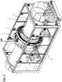
- the numeral 1 denotes an apparatus for cutting a pipe 2 made of thermoplastic material.
- the cutting apparatus 1 can advantageously be used for cutting pipes 2 made of thermoplastic material, preferably pipes 2 made of semi-crystalline thermoplastic material.
- the cutting apparatus 1 can advantageously be used for cutting pipes 2 made of polyethylene (PE) and random polypropylene (PP-R).
- PE polyethylene
- PP-R random polypropylene
- the apparatus 1 is, also, particularly suitable for cutting pipes 2 of very large diameter (greater than 80 cm) and very thick walls (greater than 9 cm).
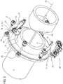
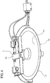
- the apparatus 1 comprises cutting means T which have a tool equipped with a disk 3 rotatable about an axis X1 and which are configured to allow the axis X1 of the disk 3 to rotate about an axis X2 of the pipe 2 and to allow the selfsame disk 3 to sink into the pipe 2 in a radial direction.
- the disk 3 can rotate freely about its own axis X1, that is to say, it is an idle disk.
- the axis X1 of the disk 3 is parallel to the axis X2 of the pipe 2 being cut.
- the disk 3 is carried by a first arm 10.
- the disk 3 is connected to a free end of the arm 10.
- the first arm 10 is rotatably connected (by a hinge) to a supporting frame 7. More specifically, the first arm 10 is hinged to the frame 7 at the point labelled 110.
- the first arm 10 is rotatable relative to the supporting frame 7.
- the first arm 10 is driven to rotate relative to the supporting frame 7 by an actuator (preferably hydraulic).
- an actuator preferably hydraulic
- the supporting frame 7 thus carries the cutting means T.
- the supporting frame 7 preferably has an annular shape.
- the supporting frame 7 is configured to be driven to rotate about the axis X2 of the pipe 2 so as to allow the rotary motion of the axis X1 of the disk 3 about the axis X2 of the pipe 2.
- the apparatus 1 also comprises actuator means A2 for driving the supporting frame 7 in the rotation relative to the axis X2 of the pipe 2.
- the actuator means A2 preferably comprise a motor coupled to the supporting frame 7 to drive the frame 7 in rotation relative to the axis X2 of the pipe 2.
- the frame 7 is supported, relative to a mounting structure, by a plurality of rotary elements (R1-R4).
- the rotary elements engage the outer periphery of the annular supporting frame 7 to allow the frame 7 to rotate about its own axis (which coincides with the axis X2 of the pipe).
- the actuator means A2 are coupled to one of the rotary elements R1-R4 (in the case illustrated, the means A2 are coupled to the rotary element R2), to drive it in rotation, thereby causing the frame 7 to rotate.
- the apparatus 1 further comprises a device I1 for opposing the pipe 2.
- the device I1 for opposing the pipe 2 comprises a rotary element 12.
- the rotary element 12 is substantially cylindrical in shape.
- the device I1 for opposing the pipe 2 prevents deflection of the pipe 2 while it is being cut.
- the rotary element 12 and the disk 3 are located relative to each other in such a way as to operate on the pipe 2 from opposite positions (preferably at 180° from each other) relative to the axis X2 of the pipe 2.
- the rotary element 12 is carried by the supporting frame 7.
- the rotary element 12 is connected to the supporting frame 7.
- the rotary element 12 is carried by a second arm 11 which is hinged (rotatably connected by a hinge) to the supporting frame 7.
- the apparatus 1 also comprises lubricating means L for the disk (3), configured to operate on at least one portion (P1, P2) - not in contact with the wall of the pipe 2 - of a face (F1, F2) of the disk 3, for releasing a predetermined quantity of lubricant on it so as to reduce the friction between the disk 3 and the pipe 2 when the portion (P1,P2) next comes into contact with the wall of the pipe 2 to be cut (that is, during cutting).
- lubricating means L for the disk (3) configured to operate on at least one portion (P1, P2) - not in contact with the wall of the pipe 2 - of a face (F1, F2) of the disk 3, for releasing a predetermined quantity of lubricant on it so as to reduce the friction between the disk 3 and the pipe 2 when the portion (P1,P2) next comes into contact with the wall of the pipe 2 to be cut (that is, during cutting).
- the predetermined quantity of lubricant is a quantity of lubricant such as to prevent dripping of the lubricant on the pipe 2, which would inevitably contaminate the pipe and would cause the problems described above with reference to the prior art.
- the lubricating means L are configured to release the predetermined quantity of lubricant on a radial portion (zone) of the disk 3 so as to lubricate the entire surface of the disk 3 while the disk 3 rotates.
- This radial portion is therefore a radial area of the disk 3 which instantaneously receives the lubricant: as the disk 3 rotates, this radial area covers different zones of the disk.
- the lubricating means L comprise means E for supplying a fluid lubricant.
- the fluid lubricant is a lubricating oil.
- the lubricating means L are configured to apply a film of lubricant on the portion (P1 ,P2) of the face (F1 ,F2) of the disk 3.
- the film is such that the fluid lubricant is prevented from dripping onto the pipe 2.
- the lubricating means L comprise first distribution units L1, operating on at least one portion of a first face F1 of the disk 3 for lubricating it, and second distribution units L2, operating on at least one portion of a second face F2 of the disk 3, which is opposite to the first face F1, for lubricating it.
- the first distribution units L1 and the second distribution units L2 each comprise a distribution element (5A,5B).
- the distribution element (5A,5B) is configured to distribute liquid lubricant while the disk 3 is moving.
- Figures 7 and 8 illustrate a distribution element 5A.
- the distribution element 5A comprises a plurality of channels 6 for distributing the lubricant and which are configured to allow the lubricant to be distributed substantially uniformly on the portion (P1,P2) of at least one face (F1,F2) of the disk 3.
- the distribution channels 6 are connected to a source of fluid lubricant.
- each distribution element (5A,5B) is covered by a layer of felt 13A,13B (or in more general terms, by a material having hygroscopic properties).
- the layer of felt 13A,13B constitutes an absorbing element 13A,13B.
- the absorbing element 13A,13B having hygroscopic properties is in direct contact with the disk 3 so as to release fluid lubricant thereon during cutting.
- the absorbing element (13A,13B) is thus configured to absorb fluid lubricant and to come into contact with the portion (P1, P2) of the face (F1, F2) of the disk 3 so as to transfer the fluid lubricant to the disk 3 as the disk 3 moves.
- first distribution units L1 and the second distribution units L2 are associated with a box-shaped container 4.
- the box-shaped container 4 has a first shell 15A and a second half shell 15B which are coupled (hinged) to each other.
- the box-shaped container 4 is connected, that is, fixed, to the first arm 10. More generally speaking, the box-shaped container 4 constitutes means C for coupling the distribution units (L1,L2) to the cutting means T and which are configured to allow the distribution units (L1,L2) to be in contact with the cutting means T so as to release lubricant on the portion (P1,P2) of the faces (F1,F2) of the disk 3.
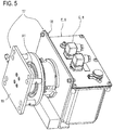
- the apparatus 1 comprises means E for supplying the fluid lubricant.
- the means E for supplying the fluid lubricant comprise a device 8 for pumping the fluid lubricant and a lubricant collection tank 9, that is to say, a lubricant source 9, to which the pumping device 8 is connected for drawing said fluid lubricant (clearly shown in Figure 5 ).
- the pumping device 8 is in fluid connection with the distribution elements (5A,5B) to supply to the distribution elements (5A,5B) the fluid lubricant drawn from the source, that is, from the collection tank 9 so that the lubricant is transferred to the disk 3.
- the pumping device 8 is in fluid connection with the distribution channels 6 through which the fluid lubricant is distributed.
- the collection tank 9 is rotatably coupled (by a hinge) to the supporting frame 7.
- the apparatus 1 comprises actuator means A1 for driving the rotation at least of the collection tank 9 relative to the supporting frame 7, these actuator means being configured to drive the rotation of the collection tank 9 during rotation of the supporting frame 7 about the axis X2 of the pipe 2, thereby maintaining a predetermined orientation of the collection tank 9.
- the collection tank 9 maintains a predetermined orientation relative to the supporting structure of the cutting apparatus 1, so as to keep the fluid lubricant in the same position inside the collection tank 9, irrespective of the angular position of the supporting frame 7 (and thus of the collection tank 9) relative to the axis X2 of the pipe 2.
- the collection tank 9 and the pumping device 8 are integrated in a structure 17 (shown clearly in Figure 5 ).
- the structure 17 is fixed to the supporting frame 7 and comprises two portions:
- the second portion 18 carries the collection tank 9 and the pumping device 8.
- the apparatus 1 comprises means (not shown in Figure 5 ) for driving the rotation of the second portion 18 relative to the first portion 16.
- These rotational drive means allow rotation of the second portion 18 relative to the first portion 16.
- the means for driving the rotation of the second portion 18 relative to the first portion 16 comprise, preferably, but not necessarily, electrical and/or hydraulic rotary joints and/or slip rings.
- the second portion 18 rotates relative to the first portion 16.
- the supporting frame 7 is carried by a mobile carriage 14 which is movable at least along the direction of extension of the axis X2 of the pipe 2.
- the cutting means T and the lubricating means L are associated with the mobile carriage 14.
- the apparatus 1 further comprises means B for locking the pipe 2, associated with the mobile carriage 14, and able to move between a non-interference position and a locked position in which they engage with the pipe 2 in order to constrain the carriage 14 relative to the pipe 2.
- the means B for locking the pipe 2 preferably comprise a pair of clamping vices movable between the non-interference position and the locked position.
- a first clamping vice is positioned to lock the pipe 2 upstream of the cutting plane (that is, of the plane in which the pipe 2 is cut) and a second clamping vice is positioned to lock the pipe 2 downstream of the cutting plane of the pipe 2.
- the cutting plane is a plane at right angles to the axis X2 of the pipe 2.
- the cutting apparatus 1 is configured to be installed in a line for the extrusion of a pipe of thermoplastic material.
- thermoplastic pipe extrusion line comprising the cutting apparatus 1 forming the object of this invention.
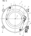
- Figures 10 to 13 illustrate operating steps of cutting a pipe 2.
- the rotational actuator means A2 are activated to carry the supporting frame 7 in rotation about the axis X2 of the pipe 2.
- the rotation of the supporting frame 7 about the axis X2 of the pipe 2 causes rotation of the axis X1 of the disc 3 about the axis X2 of the pipe 2 and a (simultaneous) rotation of the disk 3 about its own axis X1, by effect of the friction with the pipe 2 when the disk 3 comes into contact with the pipe 2 to be cut.
- the arm 10 is rotated to allow the disk 3 to sink into the wall of the pipe 2.
- Figures 10 to 13 illustrate the disk 3 with the axis X1 at different positions relative to the axis X2 of the pipe 2 and with the disk 3 sunk into the wall of the pipe 2 to different extents.
- the supporting frame 7 is carried in rotation in the direction of rotation labelled W.
- each portion of a face F1 and F2 of the disk 3 is lubricated when it enters the wall of the disk 3.
- this lubrication of the disk 3 is preferably continuous lubrication which occurs while the disk 3 rotates about its own axis X1.
- the lubricant is supplied in a quantity such as to prevent it from dripping onto the pipe 2: this advantageously prevents the lubricant from settling on the surface of the pipe 2 or inside the pipe 2. Preventing the pipe from being contaminated with the fluid lubricant is of primary importance because these pipes 2 are usually used to carry drinking water.
- Lubrication of the disk 3 is such that friction between the disk 3 and the pipe 2 during cutting is particularly reduced: this advantageously allows the apparatus 1 to cut also pipes with very large diameters and very thick walls without requiring a particularly high torque to drive the actuator means A2.
- the lubrication of the disk 3 according to the invention reduces wear of the disk 3, thus increasing the working life of the cutting disk 3 and of the apparatus 1.
- the lubricating means L are configured to release onto a portion (P1,P2) of one or both of the faces (F1,F2) of the disk 3 a solid lubricant (released in the form of particles).
- the solid lubricant may, for example, be graphite.
- the lubricating means L comprise an element (for example of graphite or other solid material) which, on contact with the disk 3, transfers lubricating particles thereon.
- the lubricating means L are configured to release onto a portion (P1,P2) of one or both of the faces (F1,F2) of the disk 3 a vaporized or atomized lubricant.
- the lubricating means L comprise nozzles designed to spray the fluid lubricant on the disk 3 in the form of a vaporized jet (vapour) or of mist.
- these lubricating means L are configured to release onto the disk 3 a quantity of lubricant such as not to drip onto the pipe 2.
- An advantage of this invention is that it provides a cutting apparatus 1 which is capable of cutting even a very large diameter and thick-walled pipe 2.
- Also defined by the invention is a method for cutting a pipe 2 made of thermoplastic material comprising the following steps:
- the cutting of the pipe 2 occurs by separation of the material.
Landscapes
- Engineering & Computer Science (AREA)
- Mechanical Engineering (AREA)
- Life Sciences & Earth Sciences (AREA)
- Forests & Forestry (AREA)
- Sawing (AREA)
- Turning (AREA)
- Perforating, Stamping-Out Or Severing By Means Other Than Cutting (AREA)
- Processing Of Stones Or Stones Resemblance Materials (AREA)
- Processing And Handling Of Plastics And Other Materials For Molding In General (AREA)
Claims (16)
- Vorrichtung zum Schneiden eines Rohres (2) gefertigt aus thermoplastischem Material, umfassend:- Schneidmittel (T), umfassend eine Schneidscheibe (3), die in der Lage ist, um eine Achse (X1) zu drehen, und ausgelegt, um eine Drehbewegung der Achse (X1) der Scheibe (3) um eine Achse (X2) des Rohres (2) und eine Versenkung der Scheibe (3) in die Wand des Rohres (2) zu ermöglichen;dadurch gekennzeichnet, dass sie- Schmiermittel (L) für die Scheibe (3) umfasst, ausgelegt, um mindestens einen Abschnitt (P1, P2) einer Seite (F1, F2) der Scheibe (3) für die Freisetzung einer vorbestimmten Menge an Schmiermittel darauf anzutreiben, um die Reibung zwischen der Scheibe (3) und dem Rohr (2) während des Schneidens zu verringern.
- Vorrichtung nach dem vorhergehenden Anspruch, wobei die Schmiermittel (L) erste Verteilereinheiten (L1) umfassen, die auf mindestens einen Abschnitt einer ersten Seite (F1) der Scheibe (3) für deren Schmierung wirken, und zweite Verteilereinheiten (L2), die auf mindestens einen Abschnitt einer zweiten Seite (F2) der Scheibe (3) für deren Schmierung wirken, die gegenüber der ersten Seite (F1) ist.
- Vorrichtung nach einem der beiden vorhergehenden Ansprüche, wobei die Schmiermittel (L) zur Freisetzung der vorbestimmten Menge an Schmiermittel auf einem radialen Abschnitt der Scheibe (3) ausgelegt sind.
- Vorrichtung nach einem der vorhergehenden Ansprüche, wobei die Schmiermittel (L) zur Freisetzung eines flüssigen Schmiermittels auf dem Abschnitt (P1, P2) der Seite (F1, F2) der Scheibe (3) ausgelegt sind.
- Vorrichtung nach Anspruch 4, wobei die Schmiermittel (L) mindestens eine Verteilereinheit (L1, L2) umfassen, die mit mindestens einem Verteilerelement (5A, 5B) ausgestattet ist, das ausgelegt ist, um ein flüssiges Schmiermittel auf dem mindestens einen Abschnitt (P1, P2) der Seite (F1, F2) der Scheibe (3) während der Bewegung der Scheibe (3) freizusetzen.
- Vorrichtung nach einem der vorhergehenden Ansprüche, umfassend mindestens eine Verteilereinheit (L1, L2) umfassend ein absorbierendes Element (13A, 13B), das ausgelegt ist, um ein flüssiges Schmiermittel zu absorbieren und den Kontakt mit dem Abschnitt (P1, P2) der Seite (F1, F2) der Scheibe (3) für die Freisetzung des flüssigen Schmiermittels während der Bewegung der Scheibe (3) herzustellen.
- Vorrichtung nach Anspruch 5 oder 6, wobei das mindestens ein Verteilerelement (5A, 5B) eine Vielzahl von Kanälen (6) für die Verteilung des flüssigen Schmiermittels umfasst, die ausgelegt sind, um die Verteilung des flüssigen Schmiermittels auf dem Abschnitt (P1, P2) mindestens einer Seite (F1, F2) der Scheibe (3) zu ermöglichen.
- Vorrichtung nach einem der vorhergehenden Ansprüche, umfassend:- einen ringförmigen Tragrahmen (7) für die Schneidmittel (T), ausgelegt, um zur Drehung um die Achse (X2) des Rohres (2) angetrieben zu werden, damit die Drehbewegung der Achse (X1) der Scheibe (3) um die Achse (X2) des Rohres (2) ermöglicht wird;- Aktuatormittel (A2) für den Antrieb der Drehung des Tragrahmens (7) relativ zur Achse (X2) des Rohres (2).
- Vorrichtung nach einem der vorhergehenden Ansprüche, wobei die Schmiermittel (L) Mittel (E) für die Versorgung eines flüssigen Schmiermittels umfassen.
- Vorrichtung nach dem vorhergehenden Anspruch, wobei die Mittel (E) für die Versorgung des flüssigen Schmiermittels eine Vorrichtung (8) für das Pumpen des flüssigen Schmiermittels und einen Schmiermittelsammelbehälter (9) umfassen, mit dem die Pumpvorrichtung (8) für das Abziehen vom flüssigen Schmiermittel verbunden ist.
- Vorrichtung nach Anspruch 10, wenn er vom Anspruch 8 abhängig ist, dadurch gekennzeichnet, dass mindestens der Sammelbehälter (9) mit dem Tragrahmen (7) drehbar gekoppelt ist, und auch dadurch gekennzeichnet, dass sie Aktuatormittel (A1) für den Antrieb der Drehung des Sammeltanks (9) relativ zum Tragrahmen (7) umfasst, wobei die Aktuatormittel ausgelegt sind, um die Drehung des Sammeltanks (9) während der Drehung des Tragrahmens (7) um die Achse (X2) des Rohres (2) anzutreiben, wodurch eine vorgegebene Ausrichtung des Tanks (9) beibehalten wird.
- Vorrichtung nach einem der vorhergehenden Ansprüche, ferner umfassend:- einen Wagen (14), in der Lage, sich mindestens in Richtung der Verlängerung der Achse (X2) des Rohres (2) zu bewegen, mit der die Schneidmittel (T) und die Schmiermittel (L) assoziiert sind;- Mittel (B) für die Verriegelung des Rohres (2), assoziiert mit dem beweglichen Wagen (14), und in der Lage, sich zwischen einer Position, in der sie das Rohr (2) nicht stören, und einer Position zu bewegen, in der sie das Rohr (2) verriegeln, wobei sie mit dem Rohr (2) einrasten, um den Wagen (14) relativ zum Rohr (2) zu beschränken.
- Verfahren zum Schneiden eines Rohres (2) gefertigt aus thermoplastischem Material, umfassend die folgenden Schritte:- Vorbereiten einer Schneidscheibe (3), in der Lage, um die eigene Drehachse (X1) zu drehen;- Lassen die Drehachse (X1) der Scheibe (3) um die Achse (X2) des Rohres (2) drehen und Vorschieben der Scheibe (3) entlang der Wand des Rohres (2), zum Schneiden des Rohres (2);- Freisetzen einer vorbestimmten Menge an Schmiermittel auf mindestens einem Abschnitt (P1, P2) einer Seite (F1, F2) der Scheibe (3) für die Schmierung der Scheibe (3) während des Schneidens, wodurch die Reibung zwischen der Scheibe (3) und dem Rohr (2) während des Schneidens verringert wird.
- Verfahren nach Anspruch 13, wobei das Schmiermittel beim Schritt der Freisetzung einer vorbestimmten Menge an Schmiermittel auf mindestens einem Abschnitt (P1, P2) einer Seite (F1, F2) der Scheibe (3) wesentlich kontinuierlich freigesetzt wird.
- Verfahren nach Anspruch 13 oder 14, wobei ein flüssiges Schmiermittel beim Schritt der Freisetzung einer vorbestimmten Menge an Schmiermittel auf mindestens einem Abschnitt (P1, P2) einer Seite (F1, F2) der Scheibe (3) freigesetzt wird.
- Verfahren nach einem der Ansprüche 13 bis 15, wobei das Schmiermittel beim Schritt der Freisetzung einer vorbestimmten Menge an Schmiermittel auf mindestens einem Abschnitt (P1, P2) einer Seite (F1, F2) der Scheibe (3) auf Abschnitte der beiden Seiten (F1, F2) der Scheibe (3) freigesetzt wird.
Applications Claiming Priority (2)
| Application Number | Priority Date | Filing Date | Title |
|---|---|---|---|
| IT000058A ITRN20120058A1 (it) | 2012-12-20 | 2012-12-20 | Apparato e metodo di taglio di tubi in materiale termoplastico. |
| PCT/IB2013/061096 WO2014097182A2 (en) | 2012-12-20 | 2013-12-18 | Apparatus and method for cutting pipes of thermoplastic material. |
Publications (2)
| Publication Number | Publication Date |
|---|---|
| EP2934830A2 EP2934830A2 (de) | 2015-10-28 |
| EP2934830B1 true EP2934830B1 (de) | 2017-08-02 |
Family
ID=47749961
Family Applications (1)
| Application Number | Title | Priority Date | Filing Date |
|---|---|---|---|
| EP13826962.6A Active EP2934830B1 (de) | 2012-12-20 | 2013-12-18 | Vorrichtung und verfahren zum schneiden von rohren aus thermoplastischem material |
Country Status (9)
| Country | Link |
|---|---|
| US (1) | US10040212B2 (de) |
| EP (1) | EP2934830B1 (de) |
| CN (1) | CN104822499B (de) |
| BR (1) | BR112015014745B1 (de) |
| CA (1) | CA2888619C (de) |
| CR (1) | CR20150223A (de) |
| IT (1) | ITRN20120058A1 (de) |
| NO (1) | NO2934830T3 (de) |
| WO (1) | WO2014097182A2 (de) |
Families Citing this family (15)
| Publication number | Priority date | Publication date | Assignee | Title |
|---|---|---|---|---|
| CN104128950B (zh) * | 2014-06-30 | 2016-03-09 | 永高股份有限公司 | 塑料管材的切割修边机 |
| EP3275581A1 (de) * | 2016-07-26 | 2018-01-31 | Aisapack Holding SA | Rotierendes schneidwerkzeug für maschine zur herstellung von verpackungen, und verfahren, bei dem dieses schneidwerkzeug zum einsatz kommt |
| IT201600104755A1 (it) * | 2016-10-18 | 2018-04-18 | Sica Spa | Apparecchiatura e metodo di riscaldamento di tubi in materiale termoplastico. |
| CN107901110A (zh) * | 2017-12-10 | 2018-04-13 | 克劳斯玛菲机械(浙江)有限公司 | 一种行星切割装置 |
| CN109227196A (zh) * | 2018-11-13 | 2019-01-18 | 黄建财 | 无屑旋切机 |
| IT202000004888A1 (it) * | 2020-03-09 | 2021-09-09 | Sica Spa | Apparato di taglio di tubi in materiale termoplastico |
| CN111389861B (zh) * | 2020-03-25 | 2021-04-30 | 赣州市束薪再生资源有限公司 | 一种钢结构建筑固体废弃物回收处理设备 |
| CN111375625B (zh) * | 2020-03-25 | 2021-05-25 | 深圳海龙建筑科技有限公司 | 一种钢结构建筑固体废弃物回收处理方法 |
| EP4244028B1 (de) * | 2020-11-11 | 2025-07-16 | Sica S.P.A. | Schneidvorrichtung für thermoplastische rohre |
| DE102020133873A1 (de) | 2020-12-16 | 2022-06-23 | Battenfeld-Cincinnati Germany Gmbh | Trenneinrichtung zum Abtrennen von extrudierten Kunststoffprofilen |
| JP7121829B1 (ja) * | 2021-05-13 | 2022-08-18 | 株式会社ヤマト | 樹脂パイプ切断システム |
| DE102022112814A1 (de) | 2022-05-20 | 2023-11-23 | Battenfeld-Cincinnati Germany Gmbh | Trenneinrichtung zum Abtrennen von extrudierten Kunststoffprofilen |
| CN116690700B (zh) * | 2023-06-16 | 2025-09-09 | 重庆伟星新型建材有限公司 | 大口径管材自动切割机及使用方法 |
| CN117162162A (zh) * | 2023-10-31 | 2023-12-05 | 南通瑞童塑业科技有限公司 | 一种可往复运动的塑胶管道切割装置 |
| CN120715971B (zh) * | 2025-08-29 | 2025-12-16 | 烟台战歌电子有限公司 | 一种液晶显示屏加工用管件切割装置 |
Citations (1)
| Publication number | Priority date | Publication date | Assignee | Title |
|---|---|---|---|---|
| DE2756529A1 (de) * | 1977-12-19 | 1979-06-21 | Horst Dr Zimmermann | Rohrschneider |
Family Cites Families (14)
| Publication number | Priority date | Publication date | Assignee | Title |
|---|---|---|---|---|
| US1958912A (en) * | 1932-01-02 | 1934-05-15 | Eastman Machine Co | Knife moistening appliance for fabric cutting machines |
| US3135304A (en) * | 1959-09-14 | 1964-06-02 | Mcculloch Corp | Roto saw |
| US3661045A (en) * | 1970-09-17 | 1972-05-09 | Tyco Lab | Apparatus for stabilizing a rotary saw blade |
| US4794832A (en) * | 1988-04-11 | 1989-01-03 | Rubber Band Technology, Ltd. | Method and apparatus for cutting and unbonding elastic bands |
| DE4332123A1 (de) * | 1993-09-22 | 1995-03-23 | Wilhelm Hegler | Vorrichtung zum Sägen von Schlitzen in Well- und Verbundrohre |
| EP0826467B1 (de) * | 1996-08-30 | 2001-11-07 | SICA S.p.A. | Verfahren zum Durchtrennen von rohrförmigem Stab |
| EP0982104B1 (de) * | 1998-08-21 | 2003-05-21 | M T C - Macchine Trasformazione Carta S.r.l. | Verfahren sowie Vorrichtung zum Bewegen des Kreismessers einer Maschine zum Schneiden von Papierrollen oder dergleichen |
| KR100431752B1 (ko) * | 2001-12-28 | 2004-05-22 | 주식회사 신진에스엠 | 금속 판재 절삭용 원형톱날 조립체 |
| DE20215642U1 (de) * | 2002-01-25 | 2003-02-06 | Heidel GmbH & Co. KG Werkzeug- u. Maschinenfabrikation, 41751 Viersen | Schneidwerkzeug |
| DE602004004840T2 (de) | 2003-09-01 | 2007-10-31 | Nippon Shokubai Co. Ltd. | Verfahren zur Herstellung von wasserabsorbierenden Harzteilchen aus Hydrogelpartikeln |
| CN201115970Y (zh) * | 2007-07-30 | 2008-09-17 | 无锡市侨诺塑机有限公司 | 塑料管道切割机的回转式切割部件 |
| CN201079965Y (zh) * | 2007-08-14 | 2008-07-02 | 上海金纬管道设备制造有限公司 | 一种塑料实壁管切割机倒角装置 |
| CN102528549A (zh) * | 2011-12-24 | 2012-07-04 | 杭州力士机械有限公司 | 切管机割刀轮润滑冷却装置及自动润滑冷却快速切管机 |
| CN102554948B (zh) * | 2012-02-03 | 2014-01-15 | 广东联塑机器制造有限公司 | 一种齿轮转盘轴承组合传动pvc管材无屑切割机构及切割机 |
-
2012
- 2012-12-20 IT IT000058A patent/ITRN20120058A1/it unknown
-
2013
- 2013-12-18 CN CN201380062480.8A patent/CN104822499B/zh not_active Expired - Fee Related
- 2013-12-18 EP EP13826962.6A patent/EP2934830B1/de active Active
- 2013-12-18 BR BR112015014745-3A patent/BR112015014745B1/pt not_active IP Right Cessation
- 2013-12-18 US US14/650,414 patent/US10040212B2/en active Active
- 2013-12-18 CA CA2888619A patent/CA2888619C/en active Active
- 2013-12-18 WO PCT/IB2013/061096 patent/WO2014097182A2/en not_active Ceased
- 2013-12-18 NO NO13826962A patent/NO2934830T3/no unknown
-
2015
- 2015-04-29 CR CR20150223A patent/CR20150223A/es unknown
Patent Citations (1)
| Publication number | Priority date | Publication date | Assignee | Title |
|---|---|---|---|---|
| DE2756529A1 (de) * | 1977-12-19 | 1979-06-21 | Horst Dr Zimmermann | Rohrschneider |
Also Published As
| Publication number | Publication date |
|---|---|
| CA2888619A1 (en) | 2014-06-26 |
| NO2934830T3 (de) | 2017-12-30 |
| WO2014097182A3 (en) | 2014-10-30 |
| CN104822499A (zh) | 2015-08-05 |
| EP2934830A2 (de) | 2015-10-28 |
| US10040212B2 (en) | 2018-08-07 |
| ITRN20120058A1 (it) | 2014-06-21 |
| WO2014097182A2 (en) | 2014-06-26 |
| CR20150223A (es) | 2015-06-24 |
| CN104822499B (zh) | 2016-10-19 |
| BR112015014745B1 (pt) | 2021-03-09 |
| CA2888619C (en) | 2019-12-03 |
| BR112015014745A2 (pt) | 2017-07-11 |
| US20150306780A1 (en) | 2015-10-29 |
Similar Documents
| Publication | Publication Date | Title |
|---|---|---|
| EP2934830B1 (de) | Vorrichtung und verfahren zum schneiden von rohren aus thermoplastischem material | |
| CA2753340C (en) | Driven tool assembly | |
| US10124418B2 (en) | Automatic movable machine for chamfering pipe and metal sheet | |
| JP2010269401A (ja) | スリッター装置 | |
| KR20110099215A (ko) | 고온 절단물을 과립화하기 위한 장치 | |
| WO2010089449A1 (en) | Pipe cutting apparatus | |
| KR20190118990A (ko) | 파이프 절단장치 | |
| US4683788A (en) | Method of and apparatus for chip-cutting of workpieces | |
| WO2010054502A1 (zh) | 一种脱去地毯背胶的方法及其设备 | |
| WO2013140208A1 (en) | Method and apparatus for cutting a pipe made from thermoplastic material | |
| JP6429330B2 (ja) | フレキシブルスピンドル送りを備えた掘削工具 | |
| CN114042992A (zh) | 波纹管切割机 | |
| EP3569350A1 (de) | Schneidvorrichtung zum schneiden von kunstoffrohren | |
| CN214722366U (zh) | 一种数控管道切断坡口机 | |
| JP5063804B1 (ja) | ロータリジョイント | |
| CN100393462C (zh) | 圆管材截面滚切机 | |
| CN109927275B (zh) | 塑钢缠绕管加工装置 | |
| CN210059953U (zh) | 可切换控制的剖分装置以及剖分机组 | |
| JPH05154859A (ja) | 合成樹脂素材供給装置及び密封ライナー形成システム | |
| US11707865B2 (en) | Underwater pelletizer | |
| RU2089380C1 (ru) | Устройство для резки рулонов полиэтиленовой пленки | |
| WO2003051567A1 (en) | Apparatus and method for slotting a pipe | |
| CN105499700A (zh) | 一种纵剪机刀片液压锁紧装置 | |
| CN206911999U (zh) | 一种伺服驱动的径向进给机构 | |
| CN215824389U (zh) | 一种切割机构及管材切割机 |
Legal Events
| Date | Code | Title | Description |
|---|---|---|---|
| PUAI | Public reference made under article 153(3) epc to a published international application that has entered the european phase |
Free format text: ORIGINAL CODE: 0009012 |
|
| 17P | Request for examination filed |
Effective date: 20150525 |
|
| AK | Designated contracting states |
Kind code of ref document: A2 Designated state(s): AL AT BE BG CH CY CZ DE DK EE ES FI FR GB GR HR HU IE IS IT LI LT LU LV MC MK MT NL NO PL PT RO RS SE SI SK SM TR |
|
| AX | Request for extension of the european patent |
Extension state: BA ME |
|
| DAX | Request for extension of the european patent (deleted) | ||
| GRAP | Despatch of communication of intention to grant a patent |
Free format text: ORIGINAL CODE: EPIDOSNIGR1 |
|
| INTG | Intention to grant announced |
Effective date: 20170310 |
|
| GRAS | Grant fee paid |
Free format text: ORIGINAL CODE: EPIDOSNIGR3 |
|
| GRAA | (expected) grant |
Free format text: ORIGINAL CODE: 0009210 |
|
| AK | Designated contracting states |
Kind code of ref document: B1 Designated state(s): AL AT BE BG CH CY CZ DE DK EE ES FI FR GB GR HR HU IE IS IT LI LT LU LV MC MK MT NL NO PL PT RO RS SE SI SK SM TR |
|
| REG | Reference to a national code |
Ref country code: CH Ref legal event code: EP Ref country code: AT Ref legal event code: REF Ref document number: 913944 Country of ref document: AT Kind code of ref document: T Effective date: 20170815 |
|
| REG | Reference to a national code |
Ref country code: IE Ref legal event code: FG4D |
|
| REG | Reference to a national code |
Ref country code: DE Ref legal event code: R096 Ref document number: 602013024534 Country of ref document: DE |
|
| REG | Reference to a national code |
Ref country code: NL Ref legal event code: FP |
|
| REG | Reference to a national code |
Ref country code: LT Ref legal event code: MG4D |
|
| REG | Reference to a national code |
Ref country code: FR Ref legal event code: PLFP Year of fee payment: 5 |
|
| REG | Reference to a national code |
Ref country code: NO Ref legal event code: T2 Effective date: 20170802 |
|
| PG25 | Lapsed in a contracting state [announced via postgrant information from national office to epo] |
Ref country code: HR Free format text: LAPSE BECAUSE OF FAILURE TO SUBMIT A TRANSLATION OF THE DESCRIPTION OR TO PAY THE FEE WITHIN THE PRESCRIBED TIME-LIMIT Effective date: 20170802 Ref country code: SE Free format text: LAPSE BECAUSE OF FAILURE TO SUBMIT A TRANSLATION OF THE DESCRIPTION OR TO PAY THE FEE WITHIN THE PRESCRIBED TIME-LIMIT Effective date: 20170802 Ref country code: LT Free format text: LAPSE BECAUSE OF FAILURE TO SUBMIT A TRANSLATION OF THE DESCRIPTION OR TO PAY THE FEE WITHIN THE PRESCRIBED TIME-LIMIT Effective date: 20170802 |
|
| PG25 | Lapsed in a contracting state [announced via postgrant information from national office to epo] |
Ref country code: GR Free format text: LAPSE BECAUSE OF FAILURE TO SUBMIT A TRANSLATION OF THE DESCRIPTION OR TO PAY THE FEE WITHIN THE PRESCRIBED TIME-LIMIT Effective date: 20171103 Ref country code: IS Free format text: LAPSE BECAUSE OF FAILURE TO SUBMIT A TRANSLATION OF THE DESCRIPTION OR TO PAY THE FEE WITHIN THE PRESCRIBED TIME-LIMIT Effective date: 20171202 Ref country code: LV Free format text: LAPSE BECAUSE OF FAILURE TO SUBMIT A TRANSLATION OF THE DESCRIPTION OR TO PAY THE FEE WITHIN THE PRESCRIBED TIME-LIMIT Effective date: 20170802 Ref country code: RS Free format text: LAPSE BECAUSE OF FAILURE TO SUBMIT A TRANSLATION OF THE DESCRIPTION OR TO PAY THE FEE WITHIN THE PRESCRIBED TIME-LIMIT Effective date: 20170802 Ref country code: BG Free format text: LAPSE BECAUSE OF FAILURE TO SUBMIT A TRANSLATION OF THE DESCRIPTION OR TO PAY THE FEE WITHIN THE PRESCRIBED TIME-LIMIT Effective date: 20171102 Ref country code: ES Free format text: LAPSE BECAUSE OF FAILURE TO SUBMIT A TRANSLATION OF THE DESCRIPTION OR TO PAY THE FEE WITHIN THE PRESCRIBED TIME-LIMIT Effective date: 20170802 Ref country code: PL Free format text: LAPSE BECAUSE OF FAILURE TO SUBMIT A TRANSLATION OF THE DESCRIPTION OR TO PAY THE FEE WITHIN THE PRESCRIBED TIME-LIMIT Effective date: 20170802 |
|
| PG25 | Lapsed in a contracting state [announced via postgrant information from national office to epo] |
Ref country code: RO Free format text: LAPSE BECAUSE OF FAILURE TO SUBMIT A TRANSLATION OF THE DESCRIPTION OR TO PAY THE FEE WITHIN THE PRESCRIBED TIME-LIMIT Effective date: 20170802 Ref country code: DK Free format text: LAPSE BECAUSE OF FAILURE TO SUBMIT A TRANSLATION OF THE DESCRIPTION OR TO PAY THE FEE WITHIN THE PRESCRIBED TIME-LIMIT Effective date: 20170802 Ref country code: CZ Free format text: LAPSE BECAUSE OF FAILURE TO SUBMIT A TRANSLATION OF THE DESCRIPTION OR TO PAY THE FEE WITHIN THE PRESCRIBED TIME-LIMIT Effective date: 20170802 |
|
| REG | Reference to a national code |
Ref country code: DE Ref legal event code: R097 Ref document number: 602013024534 Country of ref document: DE |
|
| PG25 | Lapsed in a contracting state [announced via postgrant information from national office to epo] |
Ref country code: SM Free format text: LAPSE BECAUSE OF FAILURE TO SUBMIT A TRANSLATION OF THE DESCRIPTION OR TO PAY THE FEE WITHIN THE PRESCRIBED TIME-LIMIT Effective date: 20170802 Ref country code: SK Free format text: LAPSE BECAUSE OF FAILURE TO SUBMIT A TRANSLATION OF THE DESCRIPTION OR TO PAY THE FEE WITHIN THE PRESCRIBED TIME-LIMIT Effective date: 20170802 Ref country code: EE Free format text: LAPSE BECAUSE OF FAILURE TO SUBMIT A TRANSLATION OF THE DESCRIPTION OR TO PAY THE FEE WITHIN THE PRESCRIBED TIME-LIMIT Effective date: 20170802 |
|
| PLBE | No opposition filed within time limit |
Free format text: ORIGINAL CODE: 0009261 |
|
| STAA | Information on the status of an ep patent application or granted ep patent |
Free format text: STATUS: NO OPPOSITION FILED WITHIN TIME LIMIT |
|
| 26N | No opposition filed |
Effective date: 20180503 |
|
| REG | Reference to a national code |
Ref country code: CH Ref legal event code: PL |
|
| GBPC | Gb: european patent ceased through non-payment of renewal fee |
Effective date: 20171218 |
|
| PG25 | Lapsed in a contracting state [announced via postgrant information from national office to epo] |
Ref country code: SI Free format text: LAPSE BECAUSE OF FAILURE TO SUBMIT A TRANSLATION OF THE DESCRIPTION OR TO PAY THE FEE WITHIN THE PRESCRIBED TIME-LIMIT Effective date: 20170802 |
|
| REG | Reference to a national code |
Ref country code: IE Ref legal event code: MM4A |
|
| PG25 | Lapsed in a contracting state [announced via postgrant information from national office to epo] |
Ref country code: LU Free format text: LAPSE BECAUSE OF NON-PAYMENT OF DUE FEES Effective date: 20171218 Ref country code: MT Free format text: LAPSE BECAUSE OF NON-PAYMENT OF DUE FEES Effective date: 20171218 |
|
| PG25 | Lapsed in a contracting state [announced via postgrant information from national office to epo] |
Ref country code: IE Free format text: LAPSE BECAUSE OF NON-PAYMENT OF DUE FEES Effective date: 20171218 |
|
| PG25 | Lapsed in a contracting state [announced via postgrant information from national office to epo] |
Ref country code: CH Free format text: LAPSE BECAUSE OF NON-PAYMENT OF DUE FEES Effective date: 20171231 Ref country code: GB Free format text: LAPSE BECAUSE OF NON-PAYMENT OF DUE FEES Effective date: 20171218 Ref country code: LI Free format text: LAPSE BECAUSE OF NON-PAYMENT OF DUE FEES Effective date: 20171231 |
|
| PG25 | Lapsed in a contracting state [announced via postgrant information from national office to epo] |
Ref country code: MC Free format text: LAPSE BECAUSE OF FAILURE TO SUBMIT A TRANSLATION OF THE DESCRIPTION OR TO PAY THE FEE WITHIN THE PRESCRIBED TIME-LIMIT Effective date: 20170802 Ref country code: HU Free format text: LAPSE BECAUSE OF FAILURE TO SUBMIT A TRANSLATION OF THE DESCRIPTION OR TO PAY THE FEE WITHIN THE PRESCRIBED TIME-LIMIT; INVALID AB INITIO Effective date: 20131218 |
|
| PG25 | Lapsed in a contracting state [announced via postgrant information from national office to epo] |
Ref country code: CY Free format text: LAPSE BECAUSE OF FAILURE TO SUBMIT A TRANSLATION OF THE DESCRIPTION OR TO PAY THE FEE WITHIN THE PRESCRIBED TIME-LIMIT Effective date: 20170802 |
|
| PG25 | Lapsed in a contracting state [announced via postgrant information from national office to epo] |
Ref country code: MK Free format text: LAPSE BECAUSE OF FAILURE TO SUBMIT A TRANSLATION OF THE DESCRIPTION OR TO PAY THE FEE WITHIN THE PRESCRIBED TIME-LIMIT Effective date: 20170802 |
|
| REG | Reference to a national code |
Ref country code: AT Ref legal event code: UEP Ref document number: 913944 Country of ref document: AT Kind code of ref document: T Effective date: 20170802 |
|
| PG25 | Lapsed in a contracting state [announced via postgrant information from national office to epo] |
Ref country code: PT Free format text: LAPSE BECAUSE OF FAILURE TO SUBMIT A TRANSLATION OF THE DESCRIPTION OR TO PAY THE FEE WITHIN THE PRESCRIBED TIME-LIMIT Effective date: 20170802 |
|
| PG25 | Lapsed in a contracting state [announced via postgrant information from national office to epo] |
Ref country code: AL Free format text: LAPSE BECAUSE OF FAILURE TO SUBMIT A TRANSLATION OF THE DESCRIPTION OR TO PAY THE FEE WITHIN THE PRESCRIBED TIME-LIMIT Effective date: 20170802 |
|
| PGFP | Annual fee paid to national office [announced via postgrant information from national office to epo] |
Ref country code: FI Payment date: 20201218 Year of fee payment: 8 Ref country code: FR Payment date: 20201229 Year of fee payment: 8 |
|
| PGFP | Annual fee paid to national office [announced via postgrant information from national office to epo] |
Ref country code: BE Payment date: 20201229 Year of fee payment: 8 |
|
| REG | Reference to a national code |
Ref country code: FI Ref legal event code: MAE |
|
| PG25 | Lapsed in a contracting state [announced via postgrant information from national office to epo] |
Ref country code: FI Free format text: LAPSE BECAUSE OF NON-PAYMENT OF DUE FEES Effective date: 20211218 |
|
| REG | Reference to a national code |
Ref country code: BE Ref legal event code: MM Effective date: 20211231 |
|
| PG25 | Lapsed in a contracting state [announced via postgrant information from national office to epo] |
Ref country code: FR Free format text: LAPSE BECAUSE OF NON-PAYMENT OF DUE FEES Effective date: 20211231 Ref country code: BE Free format text: LAPSE BECAUSE OF NON-PAYMENT OF DUE FEES Effective date: 20211231 |
|
| P01 | Opt-out of the competence of the unified patent court (upc) registered |
Effective date: 20230517 |
|
| PGFP | Annual fee paid to national office [announced via postgrant information from national office to epo] |
Ref country code: DE Payment date: 20241227 Year of fee payment: 12 |
|
| PGFP | Annual fee paid to national office [announced via postgrant information from national office to epo] |
Ref country code: NO Payment date: 20251218 Year of fee payment: 13 |
|
| PGFP | Annual fee paid to national office [announced via postgrant information from national office to epo] |
Ref country code: AT Payment date: 20251218 Year of fee payment: 13 |
|
| PGFP | Annual fee paid to national office [announced via postgrant information from national office to epo] |
Ref country code: IT Payment date: 20251222 Year of fee payment: 13 |
|
| PGFP | Annual fee paid to national office [announced via postgrant information from national office to epo] |
Ref country code: NL Payment date: 20251222 Year of fee payment: 13 |
|
| PGFP | Annual fee paid to national office [announced via postgrant information from national office to epo] |
Ref country code: TR Payment date: 20251128 Year of fee payment: 13 |