EP2934340B1 - Biopsievorrichtung - Google Patents
Biopsievorrichtung Download PDFInfo
- Publication number
- EP2934340B1 EP2934340B1 EP13863978.6A EP13863978A EP2934340B1 EP 2934340 B1 EP2934340 B1 EP 2934340B1 EP 13863978 A EP13863978 A EP 13863978A EP 2934340 B1 EP2934340 B1 EP 2934340B1
- Authority
- EP
- European Patent Office
- Prior art keywords
- rotary
- disposed
- base
- rotary member
- cannula
- Prior art date
- Legal status (The legal status is an assumption and is not a legal conclusion. Google has not performed a legal analysis and makes no representation as to the accuracy of the status listed.)
- Active
Links
- 238000001574 biopsy Methods 0.000 title description 111
- 238000000034 method Methods 0.000 claims description 28
- 210000004185 liver Anatomy 0.000 claims description 13
- 230000003993 interaction Effects 0.000 claims description 10
- 238000012317 liver biopsy Methods 0.000 claims description 10
- 210000005166 vasculature Anatomy 0.000 claims description 8
- 229940078979 liver therapy drug Drugs 0.000 claims description 7
- 230000000007 visual effect Effects 0.000 claims description 7
- 238000003780 insertion Methods 0.000 claims description 6
- 230000037431 insertion Effects 0.000 claims description 6
- 210000001519 tissue Anatomy 0.000 description 48
- 239000000523 sample Substances 0.000 description 46
- 238000006073 displacement reaction Methods 0.000 description 11
- 238000002560 therapeutic procedure Methods 0.000 description 10
- 230000007704 transition Effects 0.000 description 9
- 230000000712 assembly Effects 0.000 description 6
- 238000000429 assembly Methods 0.000 description 6
- 239000012530 fluid Substances 0.000 description 6
- 230000007246 mechanism Effects 0.000 description 6
- 239000007787 solid Substances 0.000 description 6
- 239000000463 material Substances 0.000 description 4
- 208000012287 Prolapse Diseases 0.000 description 3
- 239000008280 blood Substances 0.000 description 3
- 210000004369 blood Anatomy 0.000 description 3
- 230000008859 change Effects 0.000 description 3
- 210000004731 jugular vein Anatomy 0.000 description 3
- 230000004044 response Effects 0.000 description 3
- 238000011282 treatment Methods 0.000 description 3
- 239000003086 colorant Substances 0.000 description 2
- 230000008878 coupling Effects 0.000 description 2
- 238000010168 coupling process Methods 0.000 description 2
- 238000005859 coupling reaction Methods 0.000 description 2
- 230000000881 depressing effect Effects 0.000 description 2
- 230000023597 hemostasis Effects 0.000 description 2
- 210000005228 liver tissue Anatomy 0.000 description 2
- 230000002792 vascular Effects 0.000 description 2
- 241001631457 Cannula Species 0.000 description 1
- FAPWRFPIFSIZLT-UHFFFAOYSA-M Sodium chloride Chemical compound [Na+].[Cl-] FAPWRFPIFSIZLT-UHFFFAOYSA-M 0.000 description 1
- 238000005452 bending Methods 0.000 description 1
- 230000008901 benefit Effects 0.000 description 1
- 230000017531 blood circulation Effects 0.000 description 1
- 230000006835 compression Effects 0.000 description 1
- 238000007906 compression Methods 0.000 description 1
- 230000001419 dependent effect Effects 0.000 description 1
- 230000000994 depressogenic effect Effects 0.000 description 1
- 239000002648 laminated material Substances 0.000 description 1
- 238000003698 laser cutting Methods 0.000 description 1
- 230000014759 maintenance of location Effects 0.000 description 1
- 239000011780 sodium chloride Substances 0.000 description 1
- 239000011800 void material Substances 0.000 description 1
Images


Classifications
-
- A—HUMAN NECESSITIES
- A61—MEDICAL OR VETERINARY SCIENCE; HYGIENE
- A61B—DIAGNOSIS; SURGERY; IDENTIFICATION
- A61B5/00—Measuring for diagnostic purposes; Identification of persons
- A61B5/15—Devices for taking samples of blood
- A61B5/150992—Blood sampling from a fluid line external to a patient, such as a catheter line, combined with an infusion line; blood sampling from indwelling needle sets, e.g. sealable ports, luer couplings, valves
-
- A—HUMAN NECESSITIES
- A61—MEDICAL OR VETERINARY SCIENCE; HYGIENE
- A61B—DIAGNOSIS; SURGERY; IDENTIFICATION
- A61B10/00—Other methods or instruments for diagnosis, e.g. instruments for taking a cell sample, for biopsy, for vaccination diagnosis; Sex determination; Ovulation-period determination; Throat striking implements
- A61B10/02—Instruments for taking cell samples or for biopsy
- A61B10/0233—Pointed or sharp biopsy instruments
- A61B10/0266—Pointed or sharp biopsy instruments means for severing sample
- A61B10/0275—Pointed or sharp biopsy instruments means for severing sample with sample notch, e.g. on the side of inner stylet
-
- A—HUMAN NECESSITIES
- A61—MEDICAL OR VETERINARY SCIENCE; HYGIENE
- A61B—DIAGNOSIS; SURGERY; IDENTIFICATION
- A61B10/00—Other methods or instruments for diagnosis, e.g. instruments for taking a cell sample, for biopsy, for vaccination diagnosis; Sex determination; Ovulation-period determination; Throat striking implements
- A61B10/02—Instruments for taking cell samples or for biopsy
- A61B10/04—Endoscopic instruments
-
- A—HUMAN NECESSITIES
- A61—MEDICAL OR VETERINARY SCIENCE; HYGIENE
- A61B—DIAGNOSIS; SURGERY; IDENTIFICATION
- A61B17/00—Surgical instruments, devices or methods, e.g. tourniquets
- A61B17/22—Implements for squeezing-off ulcers or the like on the inside of inner organs of the body; Implements for scraping-out cavities of body organs, e.g. bones; Calculus removers; Calculus smashing apparatus; Apparatus for removing obstructions in blood vessels, not otherwise provided for
- A61B17/221—Gripping devices in the form of loops or baskets for gripping calculi or similar types of obstructions
-
- A—HUMAN NECESSITIES
- A61—MEDICAL OR VETERINARY SCIENCE; HYGIENE
- A61B—DIAGNOSIS; SURGERY; IDENTIFICATION
- A61B17/00—Surgical instruments, devices or methods, e.g. tourniquets
- A61B17/28—Surgical forceps
- A61B17/29—Forceps for use in minimally invasive surgery
-
- A—HUMAN NECESSITIES
- A61—MEDICAL OR VETERINARY SCIENCE; HYGIENE
- A61B—DIAGNOSIS; SURGERY; IDENTIFICATION
- A61B90/00—Instruments, implements or accessories specially adapted for surgery or diagnosis and not covered by any of the groups A61B1/00 - A61B50/00, e.g. for luxation treatment or for protecting wound edges
- A61B90/10—Instruments, implements or accessories specially adapted for surgery or diagnosis and not covered by any of the groups A61B1/00 - A61B50/00, e.g. for luxation treatment or for protecting wound edges for stereotaxic surgery, e.g. frame-based stereotaxis
- A61B90/11—Instruments, implements or accessories specially adapted for surgery or diagnosis and not covered by any of the groups A61B1/00 - A61B50/00, e.g. for luxation treatment or for protecting wound edges for stereotaxic surgery, e.g. frame-based stereotaxis with guides for needles or instruments, e.g. arcuate slides or ball joints
-
- A—HUMAN NECESSITIES
- A61—MEDICAL OR VETERINARY SCIENCE; HYGIENE
- A61B—DIAGNOSIS; SURGERY; IDENTIFICATION
- A61B17/00—Surgical instruments, devices or methods, e.g. tourniquets
- A61B17/00234—Surgical instruments, devices or methods, e.g. tourniquets for minimally invasive surgery
- A61B2017/00292—Surgical instruments, devices or methods, e.g. tourniquets for minimally invasive surgery mounted on or guided by flexible, e.g. catheter-like, means
- A61B2017/003—Steerable
- A61B2017/00318—Steering mechanisms
- A61B2017/00331—Steering mechanisms with preformed bends
-
- A—HUMAN NECESSITIES
- A61—MEDICAL OR VETERINARY SCIENCE; HYGIENE
- A61B—DIAGNOSIS; SURGERY; IDENTIFICATION
- A61B17/00—Surgical instruments, devices or methods, e.g. tourniquets
- A61B2017/0042—Surgical instruments, devices or methods, e.g. tourniquets with special provisions for gripping
- A61B2017/00455—Orientation indicators, e.g. recess on the handle
-
- A—HUMAN NECESSITIES
- A61—MEDICAL OR VETERINARY SCIENCE; HYGIENE
- A61B—DIAGNOSIS; SURGERY; IDENTIFICATION
- A61B17/00—Surgical instruments, devices or methods, e.g. tourniquets
- A61B17/32—Surgical cutting instruments
- A61B17/320016—Endoscopic cutting instruments, e.g. arthroscopes, resectoscopes
- A61B17/32002—Endoscopic cutting instruments, e.g. arthroscopes, resectoscopes with continuously rotating, oscillating or reciprocating cutting instruments
- A61B2017/320032—Details of the rotating or oscillating shaft, e.g. using a flexible shaft
-
- A—HUMAN NECESSITIES
- A61—MEDICAL OR VETERINARY SCIENCE; HYGIENE
- A61F—FILTERS IMPLANTABLE INTO BLOOD VESSELS; PROSTHESES; DEVICES PROVIDING PATENCY TO, OR PREVENTING COLLAPSING OF, TUBULAR STRUCTURES OF THE BODY, e.g. STENTS; ORTHOPAEDIC, NURSING OR CONTRACEPTIVE DEVICES; FOMENTATION; TREATMENT OR PROTECTION OF EYES OR EARS; BANDAGES, DRESSINGS OR ABSORBENT PADS; FIRST-AID KITS
- A61F2/00—Filters implantable into blood vessels; Prostheses, i.e. artificial substitutes or replacements for parts of the body; Appliances for connecting them with the body; Devices providing patency to, or preventing collapsing of, tubular structures of the body, e.g. stents
- A61F2/95—Instruments specially adapted for placement or removal of stents or stent-grafts
-
- F—MECHANICAL ENGINEERING; LIGHTING; HEATING; WEAPONS; BLASTING
- F04—POSITIVE - DISPLACEMENT MACHINES FOR LIQUIDS; PUMPS FOR LIQUIDS OR ELASTIC FLUIDS
- F04C—ROTARY-PISTON, OR OSCILLATING-PISTON, POSITIVE-DISPLACEMENT MACHINES FOR LIQUIDS; ROTARY-PISTON, OR OSCILLATING-PISTON, POSITIVE-DISPLACEMENT PUMPS
- F04C2270/00—Control; Monitoring or safety arrangements
- F04C2270/04—Force
- F04C2270/042—Force radial
- F04C2270/0421—Controlled or regulated
Definitions
- the present disclosure relates generally to medical devices. More specifically, the present disclosure relates to transvascular devices or other minimally invasive devices. In some embodiments the present disclosure relates to transvascular liver therapy devices, including transjugular liver biopsy devices. Relevant devices are known e.g. from US 8 043 362 B2 , US 2012/226101 A1 , US 2012/220894 A1 or US 2004/133124 A1 .
- a rotary indexing device configured for use in connection with a medical instrument, the rotary indexing device comprising: a base; and a rotary member rotatably coupled to the base and configured to be coupled to the medical instrument, the rotary member and base engaged such that interaction between the base and the rotary member releasably couples rotation of the rotary member with respect to the base at one or more stops such that rotation of the rotary member is configured to rotate the medical instrument at positions corresponding to the one or more stops.
- the rotary indexing device further comprises one or more detents configured to releasably couple rotation of the rotary member with respect to the base at the one or more stops.
- the detents comprise a protrusion disposed on the rotary member and one or more recesses disposed on the base.
- the rotary indexing device further comprises a retainer coupled to the base and a biasing element disposed between the retainer and the rotary member, the biasing element configured to exert a biasing force on the rotary member such that the protrusion tends to remain in a recess of the one or more recesses when the protrusion is aligned with the recess.
- recesses are disposed in a complete circular path on the base.
- the recesses are disposed such that the rotary member rotates between about 10 degrees and about 45 degrees between engagement with adjacent recesses, which corresponds to rotation of the medical instrument about 15 degrees between stops.
- the detents are configured to create an audible indicia of detent engagement or disengagement as the rotary member is rotated with respect to the base.
- the detents are configured to create a tactile indicia of detent engagement or disengagement as the rotary member is rotated with respect to the base.
- visual indicia which comprises different colors, correspond to different positions of detent engagement.
- the rotary member further comprises a ridge configured to engage a slot on the medical instrument.
- the medical device comprises an elongate member having a curved distal tip and a pointer coupled adjacent a proximal end of the elongate member, the pointer disposed such that a portion of the pointer lies in substantially the same plane as the curved distal tip. More preferably, visual indicia on the base are disposed such that the position of the pointer with respect to the indicia corresponds to the rotational position of the curved distal tip.
- the medical device comprises a transvascular introducer sheath. More preferably, the transvascular introducer sheath is configured to advance a liver biopsy device within a body lumen.
- the medical device comprises a transvascular liver therapy device configured for use in a transjugular intrahepatic portosystemic shunt procedure.
- the medical device comprises a drainage catheter.
- the transvascular liver therapy device further comprises a valve coupled adjacent a proximal end of the introducer sheath, the valve configured to be disposable in an open configuration and in a closed configuration.
- valve is configured to toggle between the open and closed configuration.
- the pointer is disposed between the valve and the introducer sheath.
- valve is configured to create an audible indicia when the valve is toggled between the open and closed configurations.
- valve is configured to create a tactile indicia when the valve is toggled between the open and closed configurations.
- the transvascular liver therapy device comprises an elongate member, which comprises a proximal segment, a flexible segment distal of the proximal segment, the flexible segment being more flexible than the proximal segment; and an operative segment disposed distal of the flexible segment.
- the flexible segment comprises a substantially circular cross-section
- the proximal segment comprises a substantially circular cross-section
- the flexible segment has a smaller outside diameter than the proximal segment
- the flexible segment comprises a hollow member having at least one spiral cut extending between an inside diameter and an outside diameter of the flexible segment.
- the proximal segment comprises a hollow member integrally formed with the flexible segment.
- the liver therapy device comprises a transjugular liver biopsy device.
- the elongate member comprises a stylet having a substantially circular cross-section, the operative segment comprising a partial core trough portion.
- the transvascular liver therapy device further comprising a hollow cannula disposed around the stylet, the cannula comprising a proximal segment, a flexible segment distal of the proximal segment, and an operative segment disposed distal of the flexible segment.
- the proximal and operative segments of the cannula comprise solid walls and the flexible segment of the cannula comprises more than one spiral cut in a wall of the flexible segment.
- the flexible segment of the elongate member and the flexible segment of the cannula are disposed adjacent each other.
- the proximal and operative segments of the cannula comprise solid walls and the flexible segment of the cannula comprises a spiral cut in a wall of the flexible segment of the cannula.
- the spiral cut is disposed about the flexible segment at between about four and about ten revolutions per inch.
- the spiral cut has a constant pitch along the entire flexible segment.
- the spiral cut transitions from a shallow pitch at an end of the flexible segment and a steeper pitch at a midpoint of the flexible segment.
- one or more struts are disposed along the path of the spiral cut.
- At least one strut comprises a solid member. Also most preferably, at least one strut comprises a ball portion and a socket portion.
- the elongate member comprises a cannula
- the biopsy device further comprises: a stylet disposed within the cannula, the cannula configured to extend distally beyond the stylet to obtain a tissue sample, and a cutting member coupled to an outer tubular member, the outer tubular member disposed around the cannula and the cutting member configured to sever a distal end of a tissue sample when the outer tubular member is displaced distally with respect to the cannula, the outer tubular member comprising a proximal segment; a flexible segment distal of the proximal segment, the flexible segment being more flexible than the proximal segment; and an operative segment disposed distal of the flexible segment.
- the introducer sheath comprises a curved distal tip and wherein the flexible segment is at least partially disposed along a curved path defined by the curved distal tip when the tissue sample is obtained.
- the elongate member comprises a stylet having a partial core trough and wherein the biopsy device further comprises a hollow cannula disposed around the stylet, a flexible segment of the cannula disposed adjacent the flexible segment of the stylet; and wherein obtaining a tissue sample comprises advancing the stylet into the tissue such that tissue prolapses into the trough and advancing the cannula to sever the prolapsed tissue.
- the flexible segment of the stylet and the flexible segment of the cannula are disposed in curved paths when the tissue sample is obtained.
- the elongate member comprises a cannula
- the biopsy device further comprises an outer tubular member disposed around the cannula and a cutting member coupled to the outer tubular member, a flexible segment of the outer tubular member disposed adjacent the flexible segment of the cannula; and wherein obtaining a tissue sample comprises advancing the cannula into the tissue such that the cannula severs the outside diameter of a full core tissue sample and advancing the outer tubular member such that the cutting member severs a distal end of the tissue sample.
- the flexible segment of the cannula and the flexible segment of the outer tubular member are disposed in curved paths when the tissue sample is obtained.
- Various therapies and procedures may be performed through transvascular or other minimally invasive techniques.
- one or more instruments may be introduced into the vasculature of a patient and advanced to a treatment site, and a therapy may then be performed.
- vascular access techniques may be used to treat the liver.
- a device may be configured for use in a transjugular liver biopsy procedure; i.e., a procedure directed to retrieving a liver sample through a device introduced at the jugular vein of a patient.
- phrases “connected to” and “coupled to” refer to any form of interaction between two or more entities, including mechanical, electrical, magnetic, electromagnetic, fluid, and thermal interaction.
- Two components may be coupled to each other even though they are not in direct contact with each other.
- two components may be coupled to each other through an intermediate component.
- proximal and distal are used herein to refer to opposite locations on a medical device.
- the proximal end of the device is defined as the end of the device closest to the practitioner when the device is in use by the practitioner.
- the distal end is the end opposite the proximal end, along the longitudinal direction of the device, or the end furthest from the practitioner.
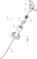
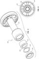
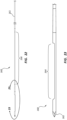
- Figure 1 is a perspective view of a transvascular biopsy assembly 100 in a first configuration.
- the assembly 100 of Figure 1 comprises various components as further detailed below. In other embodiments, any combination of the individual components may comprise an assembly or subassembly for use in connection with a transvascular procedure.
- the assembly 100 comprises an introducer sheath 110 coupled to a pointer 120 adjacent the proximal end of the introducer sheath 110.
- a delivery lumen (105 of Figure 3 ) may extend from a proximal end of the valve 140, through the pointer 120, to a distal end of the introducer sheath 110.
- a biopsy device 150 may be configured to be disposed within the delivery lumen (105 of Figure 3 ).
- the assembly may further comprise a rotary indexer 130. These components are disclosed in further detail below.
- a handle 155 of the biopsy device 150 is also shown in Figure 1 .
- a biopsy device 150 may be configured to be disposed within the delivery lumen (105 of Figure 3 ) of the introducer sheath 110, pointer 120, and valve 140. In the configuration of Figure 1 , the biopsy device 150 is shown partially disposed within the delivery lumen (105 of Figure 3 ). In some embodiments the biopsy device 150 may be configured to be delivered through the vasculature of a patient to obtain a tissue sample from the patient. For example, the biopsy device 150 may be configured to obtain a liver sample by introducing the biopsy device 150 into a vessel of the liver, then obtaining a sample. In other embodiments the biopsy device may be configured to obtain a tissue sample from another part of the body.
- the biopsy device 150 may be configured to obtain a partial core tissue sample, a full core tissue sample, a blood or other fluid sample from a particular region of the body, and so forth.
- Other treatment devices or assemblies (used in connection with or in place of the biopsy device 150) are within the scope of this disclosure.
- the assembly 100 may be configured to guide or deliver devices such as stent deployment tools, snares, balloons, probes, forceps, and so forth.
- the assembly 100 may be configured for use in connection with a transjugular intrahepatic portosystemic shunt ("TIPS") procedure.
- TIPS transjugular intrahepatic portosystemic shunt
- the assembly 100 may or may not comprise a biopsy device 150.
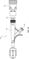
- Figure 2 is a front elevation view of a portion of the transvascular biopsy assembly 100 of Figure 1 in a second configuration
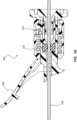
- Figure 3 is a cross-sectional view of the portion of the transvascular biopsy assembly 100 of Figure 2
- the biopsy device 150 may be axially displaceable within the delivery lumen 105 of the assembly 100.
- the biopsy device 150 is shown partially advanced within the delivery lumen 105, such that a distal end of the biopsy device 150 is disposed within a portion of the delivery lumen 105 adjacent the rotary indexer 130.
- the introducer sheath 110, the pointer 120, and the valve 140 may each comprise a lumen: an introducer sheath lumen 115, a pointer lumen 125, and a valve lumen 145.
- the introducer sheath lumen 115, the pointer lumen 125, and the valve lumen 145 may be aligned such that these lumen collectively comprise the delivery lumen 105 of the assembly 100.
- the assembly 100 may or may not include each of the introducer sheath 110, the pointer 120, and the valve 140.
- the delivery lumen 105 may only comprise a subset of the introducer sheath lumen 115, the pointer lumen 125, and the valve lumen 145.
- the assembly 100 may not include a pointer 120.
- the valve lumen 145 may be disposed directly adjacent the introducer sheath lumen 115 to form the delivery lumen 105 of the assembly 100.
- additional components of the assembly may be disposed such that lumens or openings in these additional components also comprise the delivery lumen 105.
- the rotary indexer 130 may also comprise a rotary indexer lumen 135.
- the delivery lumen 105 runs through the rotary indexer lumen 135, though the rotary indexer lumen 135 may not comprise a direct portion of the delivery lumen 105.
- these components may be arranged such that a portion of the rotary indexer lumen 135 comprises a portion of the delivery lumen 105.
- the pointer 120 has been axially advanced with respect to the rotary indexer 130 (as compared to the configuration of Figure 1 ) such that a ridge 128 of the pointer 120 is engaged with a slot 138 of the rotary indexer 130.
- This engagement may couple a rotary member 132 of the rotary indexer 130 to the pointer 120 such that rotation of the pointer 120 also rotates the rotary member 132.
- Figure 4 illustrates the introducer sheath 110, pointer 120, and valve 140 of the assembly 100 of Figure 1 .
- the pointer 120 may be fixedly coupled adjacent a proximal end 111 of the introducer sheath 110, including embodiments wherein these components are integrally formed.
- the pointer 120 may be removably coupled to the introducer sheath 110.
- the pointer 120 may be coupled to the introducer sheath 110 such that the pointer 120 and introducer sheath 110 are constrained to rotate together about a longitudinal axis of the components.
- the introducer sheath 110 may be formed of a single material, comprise a laminate material, and/or comprise a reinforced material.
- the introducer sheath 110 may be configured with a particular stiffness to facilitate a particular procedure.
- the introducer sheath 110 may be sufficiently stiff to facilitate advancement of the introducer sheath 110 along the vasculature of a patient.
- the introducer sheath 110 may comprise a curved distal tip 112. The magnitude of the curve may be greater or smaller than shown in the illustrated embodiment.
- the curved distal tip 112 may be configured to facilitate steering of the introducer sheath 110 as the introducer sheath 110 is advanced within a body lumen of a patient.
- the curved distal tip 112 may also or alternatively be configured to access a particular portion of the patient's body during a therapy. For example, during a transjugular liver biopsy procedure, an introducer sheath 110 may be advanced from an insertion point at a patient's jugular vein, through the vasculature to the patient's liver.
- the curved distal tip 112 of the introducer sheath 110 may be configured to direct instruments passed through the introducer sheath 110 (e.g., a biopsy device) such that the instruments emerge from the sheath and contact the desired tissue.
- Rotation of the introducer sheath 110 about its longitudinal axis may be configured to alter or direct the orientation or disposition of the curved distal tip 112 of the introducer sheath 110.
- the pointer 120 may be disposed such that its orientation corresponds to the orientation or direction of the curved distal tip 112 of the introducer sheath 110.
- the curved distal tip 112 of the introducer sheath may be curved substantially within a plane, and a transverse axis of the pointer 120 may lie substantially within the same plane.
- rotation of the introducer sheath 110 (which may be coupled to the pointer 120) may cause the pointer 120 to rotate such that the pointer 120 extends in the same direction as the curved distal tip 112 of the introducer sheath 110.
- the curved distal tip 112 may be disposed within a patient, and thus not directly observable by a practitioner.
- the pointer 120 may be disposed outside the patient and thereby provide the practitioner with a visual indication of the orientation of the curved distal tip within the patient's body.
- An introducer sheath 110 or any other elongate instrument configured to be positioned or otherwise controlled by rotating a curved portion thereof may be utilized in a variety of procedures within a patient's body, including transvascular procedures.
- a practitioner may control or observe the rotational position of a curved distal tip 112 through use of a pointer 120 and/or a rotary indexer 130.
- a pointer analogous to pointer 120 of Figure 4 may be used in connection with any elongate instrument.
- an analogous pointer may be coupled to a drainage catheter, a stent delivery device, a guidewire, or any other device configured to be inserted into a patient's body.
- Some such devices may be configured for use within the vasculature of a patient, while others may be configured for insertion into other body lumens, or configured for insertion into portions of the body not comprising lumens.
- the pointer 120 of Figure 4 further comprises a ridge 128 disposed on a distal portion of the pointer 120.
- the ridge 128 may be configured to engage another element of an assembly to couple the rotational displacement of the pointer 120 with the rotational displacement of the coupled element.
- the ridge 128 may couple the pointer 120 to a rotary member (132 of Figure 3 ) of a rotary indexer (130 of Figure 3 ).
- the ridge 128 or other engagement member may be disposed on the introducer sheath 110 or some other component of the assembly.
- the rotary indexer (130 of Figure 3 ) is discussed in more detail below.
- a valve 140 may be coupled to a proximal end of the pointer 120.
- the valve 140 may be configured to control flow and access to the valve lumen 145 and/or the delivery lumen 105 of the assembly.
- the valve 140 may be directly coupled to the pointer 120, including embodiments wherein the valve 140 and pointer 120 are integrally formed.
- the valve 140 may be coupled directly to the introducer sheath 110 and may be integrally formed with the introducer sheath 110.
- the valve 140 may be provided in connection with an introducer sheath 110 but no pointer 120.
- an introducer sheath 110 and pointer 120 may be configured for use without a valve 140.
- Figure 5 is an exploded view of the rotary indexer 130 of the assembly 100 of Figure 1 .
- Figure 6 is a front assembled view of the rotary indexer 130.
- the rotary indexer 130 may be configured to control the rotation and/or indicate the rotational position of certain components of the assembly.
- the rotary indexer 130 may comprise a base 131 configured to receive a rotary member 132.
- the rotary member 132 may be configured to be rotatable relative to the base 131 when the rotary indexer 130 is assembled.
- the rotary member 132 may be configured with an engagement feature, such as slot 138, configured to engage other components.
- rotation of the rotary member 132 with respect to the base 131 may also rotate an engaged component relative to the base 131.
- an assembly 100 may be configured such that the pointer 120 comprises a ridge 128 configured to engage the slot 138 of the rotary member 132.
- rotation of the introducer sheath 110 and pointer 120 may thus be coupled to rotation of the rotary member 132 with respect to the base 131.
- the ridge 128 of the pointer 120 is configured to slide into the slot 138 of the rotary member 130 when the components are engaged.
- the pointer 120 or some other component, such as the introducer sheath 110 may be fixedly coupled to the rotary member 132.
- the rotary indexer 130 may be configured such that a component such as a medical device is coupled to the base 131 such that rotation of the base 131 with respect to the rotary member 132 (which may be coupled to the pointer 120) rotates the medical device with respect to the pointer 120.
- the relative position of the pointer 120 with respect to the base 131 may still be configured to indicate the rotational position of the medical device.
- the base 131 may comprise visual indicia corresponding to the position of the pointer 120 with respect to the base 131 which indicate the position of the pointer 120 (and therefore the curved distal tip 112 of the introducer sheath 110). For example, numbers, colors, lines, and so forth on the base 131 may align with the pointer 120 and indicate the relative rotation of the curved distal tip 112 of the introducer sheath 110.
- the rotary member 132 is configured with detents or other catch mechanisms configured to releasably couple the rotary member 132 to the base 131 such that the rotary member 132 cannot easily rotate when the detents or catch mechanisms are engaged. Interaction between the rotary member 132 and the base 131 may thus allow a practitioner to rotatably displace the rotary member 132 (and therefore the pointer 120 and introducer sheath 110 in some embodiments) a certain amount, then release the rotated components. Interaction with the base 131 is configured to resist unwanted rotational displacement of these components, for example, when the practitioner desires to leave the components in place for a portion of a therapeutic procedure.
- the rotary member 132 may be coupled to the base 131 by interaction with a biasing element 133 and a retainer 134.
- the retainer 134 may be coupled to the base 131 and the biasing element 133 configured to bias the rotary member 132 into contact with a portion of the base 131.
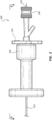
- Figure 7 is an exploded view of another embodiment of a rotary indexer 230.
- the embodiment of Figure 7 may include components that resemble components of the embodiment of Figure 5 in some respects.
- the embodiment of Figure 7 includes a rotary member 232 that may resemble the rotary member 132 of the embodiment of Figure 5 .
- all the illustrated embodiments have analogous features and components. Accordingly, like or analogous features are designated with like reference numerals, with the leading digits incremented to "2.” Relevant disclosure set forth above regarding similarly identified features thus may not be repeated hereafter.
- specific features of the system and related components shown in Figure 7 may not be shown or identified by a reference numeral in the drawings or specifically discussed in the written description that follows.
- the rotary indexer 230 shown in Figure 7 comprises a base 231, a rotary member 232, a biasing element 233, and a retainer 234. Recessed portions 237 are also shown in a surface of the base 231. When the rotary indexer 230 is assembled, the retainer 234 and biasing element 233 may interact with the rotary member 232 to bias the rotary member 232 into contact with the surface of the base 231 in which the recessed portions 237 are formed.
- Figures 8-9 are perspective views of the base 231 of the rotary indexer 230
- Figures 10-11 are perspective views of the rotary member 232 of the rotary indexer 230
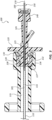
- Figure 12 is a cross-sectional view of the rotary member 232 and base 231.
- the rotary indexer 230 is configured such that detents between the rotary member 232 and the base 231 releasably couple the rotary member 232 to the base 231 such that the rotary member 232 may only rotate with respect to the base 231 when the detents are not engaged.
- the base 231 includes one or more recessed portions 237 in a surface of the base 231.
- the rotary member 232 includes a protrusion 236 configured to interact with the recessed portions 237.
- the protrusion 236 and recessed portions 237 function as detents, tending to constrain rotation of the rotary member 232 with respect to the base 231 when the protrusion 236 is disposed within a recessed portion 237.
- the biasing element 233 may tend to bias the rotary member 232 such that disengaging the protrusion 236 from a recessed portion 237 may be accomplished by overcoming the force exerted by the biasing element 233 on the rotary member 232 such that the rotary member 232 may move distally with respect to the base 231, allowing the protrusion 236 to disengage and the rotary member 232 to rotate with respect to the base 231.
- the recessed portions 237 may be disposed in an arcuate path, creating multiple detents in the path of rotational displacement of the rotary member 232.
- the detents may be spaced in a variety of configurations; for example the detents could be equally spaced about an arc, could be disposed closer or farther apart along particular segments of the arc, could increase or decrease in spacing in one direction or the other, and so forth.
- the detents may be spaced such that they represent a particular displacement of the rotary member 232 and thus, in some embodiments, the curved distal tip (112 of Figure 4 ) of an introducer sheath or other component coupled to the rotary member 232.
- the adjacent detents may represent rotational displacement of about 5 to about 25 degrees, of about 10 to about 20 degrees, or of about 15 degrees. In some embodiments there may be from about five to about nine detents disposed in an arc, or more or fewer detents disposed in an arc or complete circle.
- the spacing of the detents may be configured for use in connection with a particular therapy.
- a particular procedure may be configured to obtain multiple tissue samples from differing locations in the body.
- a practitioner may dispose a biopsy device (150 of Figure 1 ) within a vessel of a patient's liver via transvascular access. The practitioner may then obtain a first tissue sample, rotate the rotary member 232 to the next detent, obtain another tissue sample, and so forth.
- the interaction of the rotary member 232 and the base 231 may be configured to provide visual indicia of the rotational position of an instrument coupled to the rotary member 232.
- a pointer 120 of Figure 1
- Interaction of the rotary member 232 and base 231 may also be configured to provide audible or tactile indicia of the relative displacement of an instrument.
- the rotary indexer 230 may be configured such that the device creates an audible or tactile response as the detents between the rotary member 232 and base 231 engage and disengage.
- the rotary indexer 130 of Figures 1-3 and 5-6 may be configured with detents in an analogous manner to those described in connection with the rotary indexer 230 of Figures 7-12 .
- the rotary indexer 130 may comprise a base 131, a rotary member 132, a biasing element 133, and a retainer 134 disposed in an analogous manner to that discussed in connection with the embodiment of Figure 7 .
- Any configuration of detents or catches between the rotary member 132 and the base 131 are within the scope of this disclosure.
- the detents may be similar to those described in connection with Figures 7-12 .
- the cross-sectional view of Figure 3 illustrates a protrusion 136 and a recessed portion 137. As with the other embodiments, additional recessed portions may be positioned in a rotational path about the base 131.
- recesses may be formed in an outside diameter of one component with arms or tabs of a second component configured to interact therewith.
- one component may comprise a plurality of protrusions configured to interact with a plurality of recesses.
- the components and detents may be arranged to allow full 360-degree rotation of the parts.
- a rotary indexer 130 may comprise a portion of a medical device assembly, such as transvascular biopsy assembly 100. At various points during a therapy, a practitioner may rotate a portion of the assembly, utilizing the rotary indexer 130 to control the degrees of rotation (e.g., the number of stops the indexer 130 is rotated) or track the amount of rotation (e.g., by observing visual indicia, including the disposition of a pointer 120 with respect to the rotary indexer 130).
- a rotary indexer 130 is a transjugular liver biopsy.
- a practitioner may advance a liver biopsy device to a desired location within a lumen of the liver. The practitioner may then obtain a first sample, rotate the rotary indexer 130 between one or more stops, and obtain another sample.
- the rotary indexer 130 may facilitate controlling the spacing of where samples are obtained.
- a rotary indexer 130 may similarly be used in connection with a drainage catheter or other instrument disposed within a patient's body. For example, a practitioner may wish to rotate a drainage catheter in order to access various locations within the body.
- a rotary indexer 130 may facilitate control of the spacing of such displacement.
- a rotary indexer 130 may also be used in connection with a TIPS procedure.
- a practitioner may dispose a cannula within a first lumen of the liver, then attempt to advance the cannula through the liver to a second lumen of the liver, the cannula connecting the two lumens.
- the practitioner may attempt to draw blood back through the cannula; if the tip of the cannula is disposed in the second lumen, blood or other fluids from that lumen should draw through the cannula.
- the practitioner may determine the cannula is disposed within liver tissue, not within a lumen. The practitioner may then rotate the cannula in order to access a different spot, and attempt to locate the second lumen.
- a rotary indexer 130 may be configured to indicate rotational positions a practitioner has already tested as well as control rotation of the cannula.
- Rotary indexer 130 may be utilized with various other procedures or treatments. For example, placement of catheters, balloons, snares, stents, and so forth may each be done during a procedure wherein one or more components are rotated. Rotary indexers 130 may be configured to facilitate or control such rotation in any such procedure.
- FIGS 13-19 are various embodiments of valves which may be configured for use in connection with a transvascular access assembly such as the transvascular biopsy assembly 100 of Figure 1 .
- the assembly 100 of Figure 1 comprises a valve 140 coupled adjacent a proximal end of the pointer 120. Any of the valves described herein may be used in place of and/or in an analogous manner to the valve 140 of Figure 1 .
- these valves may be coupled to the assembly at various points, including embodiments wherein a valve is directly coupled to the introducer sheath 110. Luer connectors, threads, or other releasable coupling mechanisms may be used to couple the valves and/or other components.
- a pointer 120 is coupled adjacent an end of the valve 140.
- the pointer 120 may be configured to be rotatable with respect to the valve 140, or the pointer may be fixedly coupled to the valve 140.
- the valves may be releasably or fixedly coupled to a pointer (such as 120 of Figure 1 ) and/or an introducer sheath (such as 110 of Figure 1 ) when used in an assembly.
- Valves such as hemostasis valves, may be configured to allow vascular access while still maintaining a degree of hemostasis at the insertion site.
- the assembly 100 of Figure 1 may be configured such that the introducer sheath 110 is disposed within the vasculature.
- the valve 140 may be configured to allow a practitioner to access the delivery lumen (105 of Figure 3 ) with an elongate device (such as biopsy device 150 of Figure 1 ) while selectively closing the valve 140 to prevent blood flow through the delivery lumen (105 of Figure 3 ).
- valves (and related components) described below have analogous reference numerals with the leading digit incremented between embodiments.
- FIG 13 is an exploded view of an embodiment of a valve 240.
- the valve 240 may comprise a seal 242, an actuating component 244, and a valve lumen 245.
- the valve 240 may be configured such that the practitioner may selectively open and close the seal 242 to selectively allow access to the valve lumen 245.
- a practitioner may open the seal 242 in order to introduce an instrument into the valve lumen 245 and close the seal 242 in order to prevent bleed back when the therapy allows.
- the seal 242 may be configured to seal the valve lumen 245 when no instrument is disposed therein and/or to seal about an instrument that has been introduced into the valve lumen 245.
- the valve 240 may be configured with an actuator 244 configured to selectively open and close the seal 242.
- displacement of the actuator 244 may be configured to open and/or close the seal 242.
- the actuator 244 may be configured to toggle between open and closed seal 242 positions, meaning the practitioner may displace the actuator 244 to change the configuration of the seal 242 and release the actuator 244 without the seal 242 changing configurations.
- the seal 242 or actuator 244 may be biased in either the closed or open position, requiring the practitioner to maintain pressure or contact with the actuator 244 to maintain the non-biased position.
- axially displacing the actuator 244 with respect to the seal 242 may be configured to open and/or close the seal 242.
- the valve 240 may further comprise a side port 246.
- the side port 246 may be configured to allow a practitioner to introduce fluid flow (e.g., contrast fluid, saline, etc.) into the valve lumen 245 whether the seal 242 is open or closed. Flow through or pressure within the side port 246 may prevent bleed back through the side port 246.
- fluid flow e.g., contrast fluid, saline, etc.
- Figure 14 is a perspective view of another embodiment of a valve 340
- Figure 15 is an exploded view thereof
- Figure 16 is a cross-sectional view of a portion thereof.
- Figure 16 further includes an elongate device 350 disposed within a valve lumen 345 of the valve 340.
- the valve 340 of Figures 14-16 comprises a seal 342, an actuator 344, a valve lumen 345, and a side port 346. These components may function analogously to similarly indicated components of the valve 240 of Figure 13 .
- the actuator 344 of the valve 340 of Figures 14-16 may be a lever, which may be biased in an extended position. Depressing the actuator 344 may open or close the seal 342 depending on the arrangement of internal components of the valve 340. For example, the seal 342 may be compressed in a closed position when the actuator 344 is extended and may open as the actuator 344 is depressed.
- a mechanism such as a lever actuator 344 may be configured to allow a practitioner to incrementally open or close the seal 342 by incrementally depressing the actuator 344. This may allow a practitioner to open the seal 342 just enough to facilitate displacement of an elongate device 350 within the valve lumen 345 without opening the seal 342 such that there is bleed back around the elongate device 350.
- the elongate device 350 may comprise, for example, a biopsy device, a catheter, a stent delivery device, or any other transvascular therapy device.
- the seal 342 is closed about the elongate device 350 disposed in the valve lumen 345.
- Figure 17 is a perspective view of another embodiment of a valve 440
- Figure 18 is an exploded view thereof
- Figure 19 is a cross-sectional view of a portion thereof.
- Figure 19 further includes an elongate device 450 disposed within a valve lumen 445 of the valve 440.
- the valve 440 of Figures 17-19 comprises a seal 442, an actuator 444, a valve lumen 445, and a side port 446. These components may function analogously to similarly indicated components of the valves 240, 340 of Figures 13-16 .
- the actuator 444 of the valve 440 of Figures 17-19 may be configured such that axially displacing the actuator 444 in a distal direction with respect to the seal 442 causes a distal portion of the actuator 444 to interact with the seal 442, forcing the seal 442 open. Retracting the actuator 444 in a proximal direction with respect to the seal 442 may remove the actuator 444 from contact with the seal 442, allowing the seal 442 to close.
- the actuator 444 may be configured to remain in the open or closed configuration whether or not the practitioner is applying a force to the actuator 444, or the actuator 444 may be biased in one position or the other.
- the actuator 444 may be configured to provide an audible and/or tactile indication that the seal 442 has been opened and/or closed.
- the actuator 444 may be configured with ridges 447 configured to interact with other portions of the valve 440.
- Features such as ridges 447 or other detents may be configured to maintain the position of the actuator 444 (and therefore the seal 442) and/or provide an audible or tactile indication that the seal 442 has been changed from one configuration to another.
- the valve 440 of Figure 18 may further comprise a rotary member 443.
- the rotary member 443 may be configured to interact with threads positioned on another portion of the valve 440 such that the rotational position of the rotary member 443 controls compressive forces acting on a conical member 441.
- the conical member 441 may be configured such that, when compressed, the conical member 441 tends to engage an elongate instrument disposed within the valve lumen 445.
- compression of the conical member 445 couples such an instrument to the valve 440. This coupling may also act as a secondary seal, in connection with seal 442.
- any of the valves disclosed in any embodiment herein may comprise certain features described in connection with any other embodiment.
- any of the valves may be configured to produce an audible and/or tactile indication of a change to the configuration of the valve.
- Other features of each embodiment may be analogously applied to the other embodiments.
- a valve 140 may be used in connection with a medical device assembly such as transvascular liver biopsy assembly 100.
- a practitioner may insert an introducer sheath 110 into a patient with the valve 140 in a closed configuration. The practitioner may then open the valve 140 and insert a biopsy assembly 150 into the introducer sheath 110. Once the biopsy assembly 150 is inserted, the practitioner may then close the valve 140. The assembly may then be rotated (for example, the introducer sheath 110 may be rotated in connection with the rotary indexer 130) or otherwise manipulated into a desired position or configuration.
- the biopsy assembly 150 may then be used to obtain a tissue sample, with the valve 140 still in the closed configuration.
- the valve 140 may then be disposed in the open configuration and the biopsy assembly 150 withdrawn.
- the valve 140 may again be closed.
- the configuration of the valve 140 may be other than that described, depending on the therapy or practitioner preference. For example, a practitioner may open the valve 140 when actuating a biopsy assembly 150 to obtain a sample or when manipulating the position of the assembly 100 or any component thereof. Further, a practitioner may advance or retract a component, such as biopsy assembly 150, with the valve 140 in a closed configuration, essentially pushing or pulling the component while in contact with a seal of the valve 140.
- valves configured to toggle between the open and closed configurations without requiring a practitioner to maintain contact with an actuator, or valves biased in either the open or closed position (which change to the non-biased configuration only in response to continued input at an actuator) may each be used in connection with any of the procedures disclosed herein.
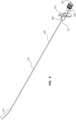
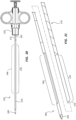
- FIG 20 is a side view of the biopsy assembly 150 of the assembly 100 of Figure 1 .
- the biopsy assembly 150 may comprise a handle 155 configured to manipulate, fire, or otherwise operate other components of the biopsy assembly 150, such as needles, trocars, stylets, cannulas, and so forth, in order to obtain a tissue sample. Any handle 155 shape, style, or design is within the scope of this disclosure.
- the biopsy assembly 150 of Figure 20 further comprises a stylet 160 disposed within a cannula 170.
- the stylet 160 and cannula 170 may be operably coupled to handle 155 such that manipulation or actuation of the handle 155 is configured to advance or retract the stylet 160 and/or cannula 170 in order to obtain a tissue sample.
- the biopsy assembly 150 of Figure 20 may further comprise one or more outer sheath members (not shown), which may be disposed around the cannula 170 and/or stylet 160.
- An outer sheath member may be configured to deliver or protect the operative components and may be fixedly coupled to the handle 155.
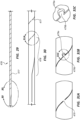
- FIG 21 is an exploded perspective view of the stylet 160 and cannula 170 of the biopsy assembly 150 of Figure 20 .
- the stylet 160 may comprise a sharp distal end 162 configured to be advanced through tissue.
- a recessed trough 164 on the stylet 160 may be configured to isolate a tissue sample, which may be severed by the cannula 170.
- the stylet 160 may be advanced into tissue such that the trough 164 of the stylet 160 extends beyond a distal tip 172 of the cannula 170. Tissue may prolapse into, or otherwise enter, the void formed by the trough 164.
- Tissue within the trough 164 may then be severed by the distal tip 172 of the cannula 170 as the cannula is distally advanced with respect to the stylet 160.
- a distal segment 174 of the cannula 170 may then retain the severed tissue within the trough 164.
- the stylet 160 and cannula 170 may then be retracted together to remove the severed tissue sample.
- a biopsy assembly 150 may be configured to traverse an introducer sheath 110 or other path when positioning the distal tip 162 of the stylet 160 adjacent desired tissue within the body.
- the stylet 160 and cannula 170 may thus comprise elongate proximal segments 161, 171, respectively, configured to advance the distal tips 162, 172 of these components within the body.
- the proximal segments 161, 171 may operably connect the distal tips 162, 172 to the handle 155 while allowing the distal tips 162, 172 to be offset from the handle 155.
- the length of the proximal segments 161, 171 may be related to the therapy for which the biopsy assembly 150 is configured for use.
- the biopsy assembly 150 may be configured for use in connection with a transjugular liver biopsy.
- the proximal segments 161, 171 may be sized such that the handle 155 may be disposed proximally of the insertion site, while the distal tips 162, 172 are disposed adjacent liver tissue to be biopsied.
- an introducer sheath 110 configured for use in connection with a biopsy assembly 150 may comprise a curved distal tip 112.
- the biopsy assembly 150 may comprise flexible segments configured to traverse the curvature of the curved distal tip 112.
- the stylet 160 and cannula 170 may each comprise a flexible segment 166, 176 disposed distally of the proximal segments 161, 171 of each component.
- the flexible segments 166, 176 may be configured to traverse a curved path and/or be disposed in a curved path when the biopsy assembly 150 is in use.
- Operative segments or segments configured to isolate, sever, or contain tissue samples may be disposed distally of the flexible segments 166, 176.
- any of these components may be configured with multiple flexible segments disposed at various locations in order to facilitate use of the biopsy assembly 150 across delivery paths comprising multiple bends or curves.
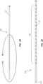
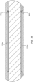
- Figure 22 is a side view of the stylet 160 of the biopsy assembly 150 of Figure 20
- Figure 23 is an enlarged view of a portion of the stylet 160 of Figure 22 , taken around line 23-23.
- Figures 22 and 23 illustrate a portion of the proximal segment 161 of the stylet 160, as well as the flexible segment 166, the trough 164, and the sharp distal tip 162.
- the stylet 160 may be generally formed of an elongate member having a generally circular cross-section. Certain features, such as the trough 164, may be formed by removing material from the generally circular member.
- the flexible segment 166 may be formed by grinding or otherwise removing material such that the flexible segment 166 has a smaller outside diameter than the proximal segment 161.
- the stylet 160 may comprise tapered or transition zones between the smaller-diameter flexible segment 166 and the proximal segment 161 and/or the operative distal end of the stylet 160.
- the flexible segment 166 may have a generally circular cross-section.
- the flexible segment 166 may have a cross-section other than a circular cross-section, including in embodiments where the proximal segment 161 has a generally circular cross-section.
- elongate members which may be configured to be passed through a sheath, are discussed herein.
- stylet 160 of Figures 22-23 cannula 170 of Figures 24 and 25 , analogous stylets-such as 760 of Figure 36 -and analogous cannula-such as 770 of Figure 36 -of other embodiments, and the outer tubular member 780 of Figure 36 ).
- Any of these elongate instruments may be configured with a flexible segment.
- the flexible segment may be characterized as more flexible than another portion of the elongate instrument, such as a portion of the instrument disposed proximally or distally of the flexible segment.
- a flexible segment may be more flexible than an operative segment disposed distally of the flexible segment.
- the apparent bending modulus of the segments may be used to compare relative flexibilities.
- the relative flexibility of various segments may be determined by measuring the force required to deflect portions of identical lengths an identical amount. In some instances, the force required to deflect a length of a flexible segment a particular amount is an order of magnitude less than the force required to deflect a stiffer segment (either proximal or distal) having the same length, the same amount.
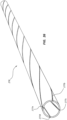
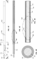
- Figure 24 is a side view of the cannula 170 of the biopsy assembly 150 of Figure 20 .
- Figure 25 is an enlarged view of a portion of the cannula 170 of Figure 24 , taken around line 25-25.
- Figures 24 and 25 illustrate the proximal segment 171 of the cannula 170, as well as the flexible segment 176 and the distal tip 172.
- the cannula 170 may comprise a generally hollow member.
- the flexible segment 176 may be formed by creating a spiral cut 177 in the wall of the hollow member.
- the spiral cut 177 may extend completely through a wall of the hollow member, from the outside diameter to the inside diameter.
- the spiral cut 177 may extend in one continuous helix along the flexible segment 176, or may be comprised of multiple cuts extending along certain portions of the flexible segment 176.
- Spiral cuts described in connection with this or any other embodiment here may be formed by laser cutting, grinding, mechanical cutting, or any other method.
- Flexible segments such as segment 166 of Figure 22 and segment 176 of Figure 25 , may be positioned at various points along members of any biopsy device or similar device within the scope of this disclosure. Any disclosure provided herein in connection with the flexible segment of a solid member (such as flexible segment 166 of Figure 22 ) may be applied to any other elongate solid member of any embodiment of a biopsy device or other medical device. Similarly, any disclosure provided herein in connection with the flexible segment of a hollow member (such as the flexible segment 176 of Figure 25 ) may be applied to any other elongate hollow member of any embodiment of a biopsy device or other medical device.
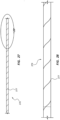
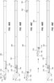
- Figure 26 is a side view of another embodiment of a flexible segment 276 of a component of a biopsy assembly.
- the flexible segment 276 comprises four spiral cuts 277a, 277b, 277c, 277d extending from an outside diameter to an inside diameter of the flexible segment 276.
- the spiral cuts 277a, 277b, 277c, 277d may be disposed such that the cuts do not cross each other, or may be disposed to cross at certain points.
- the cuts 277a, 277b, 277c, 277d may or may not be substantially parallel along the length of the cuts 277a, 277b, 277c, 277d. While the illustrated embodiment comprises four spiral cuts, other embodiments may comprise one, two, three, five, six, seven, eight, or any other number of spiral cuts. Further, certain embodiments may have segments of a different number of cuts at different points along the length of the flexible segment. For example, a flexible segment may have one spiral cut that runs the entire length of the flexible segment and additional spiral cuts that only extend along a portion of the length of the flexible segment.
- Figure 27 is a side view of another embodiment of a flexible segment 376 of a component of a biopsy assembly.
- Figure 28 is an enlarged view of a portion of the flexible segment 376 of Figure 27 , taken around line 28.
- the flexible segment 376 comprises one spiral cut 377 extending the entire length of the flexible segment 376.
- the spiral cut 377 is configured with a constant pitch along the entire length of the flexible segment 376. The pitch may be from about four revolutions per inch to about ten revolutions per inch, including about five, six, seven, eight, or nine revolutions per inch or any partial number in the range, such as 7.5 revolutions per inch.
- Figure 29 is a side view of another embodiment of a flexible segment 476 of a component of a biopsy assembly.
- Figure 30 is an enlarged view of a portion of the flexible segment 476 of Figure 29 , taken around line 30-30.
- Figure 31A is an enlarged view of a portion of the flexible segment 476 of Figure 30 , taken around line 31A.
- a spiral cut 477 in the flexible segment 476 comprises a transition portion 478.
- the pitch of the spiral cut 477 is not constant in the transition portion 478. Rather, it transitions from no pitch (or aligned with a longitudinal axis of the flexible segment 476) to a pitch about the flexible segment 476.
- a spiral cut may begin at an end of the flexible segment 476 with very little or no pitch.
- the spiral cut 477 may then transition to a constant pitch, continuously vary along the length of the flexible segment 476, or vary for portions and remain constant for portions of the flexible segment 476.
- a spiral cut 477 with a transition portion 478 having a shallow pitch disposed at an end of the flexible segment 476 may be configured to reduce stress concentrations at the end of the flexible segment 476.
- a flexible segment may have a transition portion 478 at a distal end of the flexible segment, the proximal portion of the flexible segment, or both.
- Flexible segments having multiple spiral cuts may also be configured with a transition portion or other segment of non-constant pitch.
- the embodiment of Figures 29-31A further comprises struts 479 disposed along the length of the spiral cut 477.
- the struts 479 may comprise small portions of the member which are not removed to form the spiral cut 477.
- the struts 479 may be configured to transfer longitudinal forces along the length of the flexible segment 476 while still increasing the flexibility of the flexible segment 476 with a spiral cut 477.
- Figure 31B is an enlarged view of another embodiment of a portion of a flexible segment, analogous to the view of Figure 31A , showing another embodiment of a strut.
- Figure 31C is an enlarged view of a portion of Figure 31B .
- the strut comprises a socket portion 479a and a ball portion 479b. These components may be disposed to provide a strut structure which may flex along and around the strut itself.
- a top portion of the ball portion 479b may be removed, such that the top of the ball portion 479b does not contact the socket portion 479a when the flexible portion is compressed along its axis.
- opposing sides of the spiral cut itself may contact each other to bear a compressive force.
- This design may prevent the ball portion 479b from being easily deformed in response to compressive forces.
- Struts that comprise a socket portion 479a and a ball portion 479b may be configured to transfer longitudinal forces along the length of a flexible segment.
- Some spiral cuts may be configured with no struts, some may comprise only struts such as that illustrated in Figure 31A , others comprise only struts such as that shown in Figures 31B and 31C , while other embodiments comprise struts of both varieties at various points along a spiral cut.
- Figure 32 is a top view of a portion of an operative segment of another embodiment of a portion of a biopsy assembly;
- Figure 33 is a side view of a portion of the operative segment of Figure 32;
- Figure 34 is an enlarged view of the portion of the operative segment of Figure 33 , taken around line 34-34.
- features of a sharpened distal tip 572 of a hollow biopsy device member are shown.
- the sharpened distal tip 572 may be configured to sever a tissue sample disposed within a recessed trough (such as trough 164 of Figure 23 ).
- the sharpened distal tip 572 may be configured both to sever the longitudinal length of the tissue sample and to interact with a distal end of a trough (such as trough 164 of Figure 23 ) to sever the distal end of the sample.
- angle ⁇ may vary from about 8 degrees to about 11 degrees, angle ⁇ from about 33 degrees to about 39 degrees, and angle ⁇ from about 18 degrees to about 21 degrees.
- Figures 35A-35C are side views of a portion of a biopsy assembly in a first configuration, a second configuration, and a third configuration, respectively.
- the biopsy assembly may be operated by first advancing the device in the configuration of Figure 35A to a position within the body adjacent a site to be biopsied.
- the device may be advanced through an introducer sheath (such as introducer sheath 110 of Figure 4 ), including transjugular procedures wherein the introducer sheath is introduced to the vasculature at the jugular vein.
- the biopsy device may be positioned adjacent a portion of the liver to be biopsied.
- flexible segments may be disposed in a curved portion of the introducer sheath (such as curved distal tip 112 of Figure 4 ) when the sample is obtained.
- the illustrated embodiment comprises a stylet 660 having a distal end 662 and a recessed trough 664.
- the illustrated embodiment further comprises a cannula 670 which may be disposed over stylet 660.
- the cannula 670 may comprise a sharpened distal tip 672.
- the sample may be obtained by advancing the stylet 660 with respect to the cannula 670 such that the distal tip 662 of the stylet 660 and the trough 664 extend beyond the distal tip 672 of the cannula 670, as shown in Figure 35B , and into the tissue to be biopsied. Tissue may then prolapse into the recessed trough 664 of the stylet 660.
- the cannula 670 may then be advanced such that the distal tip 672 of the cannula 670 severs the length of the sample (along the length of the trough 664) and the distal end of the sample by interaction with the distal end of the trough 664, as shown in Figure 35C .
- the biopsy assembly may be configured with springs or other mechanisms such that the components displace to obtain the sample automatically when the device is actuated.
- Figure 36 is a top view of a portion of another embodiment of a biopsy assembly.
- the biopsy assembly of Figure 36 comprises a stylet 760, a cannula 770, and an outer tubular member 780.
- the cannula 770 and outer tubular member 780 may be configured to sever a tissue sample. Any of the disclosure above relating to any other biopsy device, including the positioning and function of flexible segments, may be applicable to biopsy devices with a cannula 770 and outer tubular member 780 such as in Figure 36 .
- Figure 37 is an enlarged view of a portion of the biopsy assembly of Figure 36 , taken around line 37-37.
- the stylet 760 may comprise a sharpened distal tip 762.
- the cannula 770 may comprise an opening 775 configured to receive a cutting member 785 coupled to the outer tubular member 780.
- Figure 38 is a side view of a portion of the stylet 760 of the biopsy assembly of Figure 36 .
- the stylet 760 comprises a sharpened distal tip 762, a proximal segment 761, and a flexible segment 766.
- the stylet 760 may comprise a generally solid circular member wherein the diameter of the flexible segment 766 is smaller than the diameter of the proximal segment 761.
- the stylet 760 may not comprise a recessed trough, because in the embodiment of Figures 36-46D , the cannula 770 and outer tubular member 780 interact to isolate and sever a tissue sample.
- Figure 39 is a side view of a portion of the cannula 770 of the biopsy assembly of Figure 36 .
- the cannula 770 comprises a sharpened distal tip 772, a flexible segment 776, and a proximal segment 771 which may be less flexible than the flexible segment 776.
- the cannula 770 may comprise a generally hollow member, and the flexible segment 776 may comprise a spiral cut 777 extending between the inside diameter and the outside diameter of the member. Any spiral cut arrangement disclosed herein may be applied to the cannula 770 of this embodiment or any other hollow member of this embodiment, such as the outer tubular member (780 of Figure 40 ), for example.
- the cannula 770 may also comprise an opening 775 and slots 773a, 773b configured to interact with the outer tubular member (780 of Figure 40 ) as further disclosed below.
- the slots 773a, 773b, opening 775 and other features of the cannula 770 or other elongate members are not necessarily drawn to scale for illustrative purposes.
- Figure 40 is a side view of the outer tubular member 780 of the biopsy assembly of Figure 36 .
- the outer tubular member 780 may comprise a cutting member 785 and a flexible segment 786 which may comprise a spiral cut 787.
- a proximal segment (not shown), which may be less flexible than the flexible segment 786, may be disposed proximally of the flexible segment 786.
- the outer tubular member 780 may also comprise a tabs 783a, 783b configured to interact with a slots (773a, 773b of Figure 39 ) as further described below.
- Figure 41 is a side view of a portion of the biopsy assembly of Figure 36 ;
- Figure 42 is a cross-sectional view of the portion of the biopsy assembly of Figure 41 , taken through plane 42-42; and
- Figure 43 is a cross-sectional view of the portion of the biopsy assembly of Figure 41 , taken through plane 43-43.
- the stylet 760, the cannula 770, and the outer tubular member 780 are shown in these views.
- the stylet 760 may be disposed within the cannula 770, and the outer tubular member 780 may be disposed around the cannula 770.
- the sharpened distal tip 762 of the stylet 760, the opening 775 of the cannula 770, and the cutting member 785 and tabs 783a, 783b of the outer tubular member 780 are also shown.
- Figure 44 is an enlarged view of a portion of the cross-sectional view of Figure 42 , taken around line 44-44.
- Figure 44 illustrates two slots 773a of the cannula 770 as well as two tabs 783a of the outer tubular member 780.
- the stylet 760 is also shown.
- Figure 45 is a further enlarged view of a portion of the cross-sectional view of Figure 44 , taken around line 45-45, further illustrating a slots 773a and tabs 783a.
- two slots 773a and tabs 783a, disposed at 180 degrees to each other, are shown.
- the assemblies may comprise multiple slots and tabs positioned around a circumference of the assembly at the same longitudinal position.
- additional slots such as 773b of Figure 39
- tabs such as 783b of Figure 40
- additional slots such as 773b of Figure 39
- tabs such as 783b of Figure 40
- the tabs 783a, 783b may be configured to engage the slots 773a, 773b such that the outer tubular member 780 and cannula 770 are coupled such that they cannot rotate relative to each other at the engagement point.
- both the outer tubular member 780 and cannula 770 may be configured with flexible segments which may comprise one or more spiral cuts on each member. These flexible segments may have differing spring constants, and thus the outer tubular member 780 and cannula 770 of an assembly may tend to rotate to different degrees as the assembly is advanced along a path.
- the tabs 783a, 783b and slots 773a, 773b may be configured to retain the relative rotational positions of the outer tubular member 780 and cannula 770 as the assembly is advanced along a path. Retention of such alignment may tend to keep other components (such as the cutting member 785 and opening 775 of Figure 46A ) aligned while the assembly is in use.
- the slots 773a, 773b may be sized such that the cannula 770 and outer tubular member 780 may be axially displaceable relative to each other (for example during actuation of the assembly as described below) while still retaining the rotational positions of these components.
- the tabs may be disposed on the cannula 770 and configured to interact with slots on the outer tubular member 780.
- Figures 46A-46E are side views of a portion of the biopsy assembly of Figure 36 in five configurations.
- the outer tubular member 780, cutting member 785, cannula 770, distal tip of the cannula 772, opening 775, stylet 760, and distal tip of the stylet 762 are shown in these views.
- Figures 46A-46E illustrate five positions of the assembly during a procedure.
- the biopsy assembly of these figures may be used in connection with a variety of procedures, including transvascular procedures.
- the biopsy assembly may be advanced through an introducer sheath (such as introducer sheath 110 of Figure 4 ).
- the assembly may be configured such that the flexible segments of the outer tubular member 780, cannula 770, and stylet 760 are disposed within a curved portion (such as the curved distal tip 112 of Figure 4 ) when the biopsy assembly is actuated to obtain a sample.
- displacement of particular portions of the biopsy assembly may be controlled by a handle (such as handle 155 of Figure 20 ).
- springs or other mechanisms may displace the components of the biopsy assembly to obtain a sample once the biopsy assembly is actuated.
- the biopsy assembly may be advanced within a sheath or other path with the components in the configuration shown in Figure 46A .
- the biopsy assembly may be advanced along a delivery lumen and/or be pushed into tissue until the biopsy assembly is adjacent tissue to be biopsied.
- the distal tip 762 of the stylet 760 may be configured to pierce or separate tissue as the assembly is advanced within tissue. While the assembly is advanced or operated, the slots (773a of Figure 45 ) and tabs (783a of Figure 45 ) may resist relative rotation of the outer tubular member 780 and cannula 770 with respect to each other.
- the cannula 770 may be advanced distally beyond the distal tip 762 of the stylet 760 when the assembly is actuated.
- the distal tip 772 of the cannula 770 may extend into tissue, severing a longitudinal length of the tissue sample as the cannula 770 is advanced.
- the outer tubular member 780 may then be advanced with respect to the cannula 770.
- the cutting member 785 of the outer tubular member 780 may pass through the opening 775 in the cannula 770 such that the cutting member 785 severs a distal end of the tissue sample.
- a tissue sample may then be disposed proximally of the cutting member 785 and distally of the distal tip 762 of the stylet 760.
- the entire assembly may then be retracted together, as shown in Figure 46D , to retrieve the tissue sample from the body.
- the assembly may be pulled back along a delivery path in the configuration of Figure 46D with a sample disposed within the assembly, between the cutting member 785 and the distal tip 762 of the stylet 760.
- the cannula 770 may be advanced with respect to the outer tubular member 780 such that the cutting member 785 is no longer disposed within the cannula 770, as shown in Figure 46E .
- the stylet 760 may then be advanced with respect to the cannula 770 and outer tubular member 780 such that the stylet 760 forces the sample out of the cannula 770.
Claims (12)
- Drehbare Indexierungsvorrichtung (130; 230), eingerichtet zur Verwendung in Verbindung mit einem medizinischen Instrument, wobei die drehbare Indexierungsvorrichtung umfasst:eine Basis (131; 231);ein Drehelement (132; 232), das drehbar mit der Basis gekoppelt und eingerichtet ist, mit dem medizinischen Instrument gekoppelt zu werden, wobei Drehelement und Basis so ineinandergreifen, dass die Wechselwirkung zwischen der Basis und dem Drehelement die Drehung des Drehelements in Bezug auf die Basis an einem oder mehreren Anschlägen lösbar koppelt, so dass die Drehung des Drehelements eingerichtet ist, das medizinische Instrument an Positionen zu drehen, die dem einen oder den mehreren Anschlägen entsprechen,wobei die drehbare Indexierungsvorrichtung eine oder mehrere Arretierungen (136, 137; 236, 237) aufweist, die eingerichtet sind, die Drehung des Drehelements in Bezug auf die Basis an dem einen oder den mehreren Anschlägen zu koppeln, so dass sich das Drehelement nur dann in Bezug auf die Basis drehen kann, wenn die eine oder die mehreren Arretierungen nicht in Eingriff sind; undeine medizinische Vorrichtung, dadurch gekennzeichnet, dass die medizinische Vorrichtung mit dem Drehelement so gekoppelt ist, dass eine Drehung des Drehelements auch die medizinische Vorrichtung dreht, wobei die medizinische Vorrichtung ein längliches Element (110) mit einer gekrümmten distalen Spitze (112) und einem Zeiger (120) aufweist, der benachbart zu einem proximales Ende des länglichen Elements gekoppelt ist, wobei der Zeiger so angeordnet ist, dass ein Abschnitt des Zeigers im Wesentlichen in der gleichen Ebene liegt wie die gekrümmte distale Spitze.
- Drehbare Indexierungsvorrichtung nach Anspruch 1, wobei die Arretierungen einen Vorsprung (136; 236) aufweisen, der an dem Drehelement angeordnet ist, und eine oder mehrere Aussparungen (137; 237), die an der Basis angeordnet sind.
- Drehbare Indexierungsvorrichtung nach Anspruch 2, die ferner einen Halter (134; 234) aufweist, der mit der Basis gekoppelt ist, und ein Vorspannelement (133; 233), das zwischen dem Halter und dem Drehelement angeordnet ist, wobei das Vorspannelement eingerichtet ist, eine Vorspannkraft auf das Drehelement auszuüben, so dass der Vorsprung dazu neigt, in einer Aussparung der einen oder mehreren Aussparungen zu bleiben, wenn der Vorsprung auf die Aussparung ausgerichtet ist.
- Drehbare Indexierungsvorrichtung nach einem der Ansprüche 2 oder 3, wobei die Aussparungen auf einer vollständigen Kreisbahn auf der Basis angeordnet sind.
- Drehbare Indexierungsvorrichtung nach einem der Ansprüche 2, 3 oder 4, wobei die Aussparungen so angeordnet sind, dass sich das Drehelement zwischen etwa 10 Grad und etwa 45 Grad zwischen dem Eingreifen in benachbarte Aussparungen dreht, was einer Drehung des medizinischen Instruments um etwa 15 Grad zwischen den Anschlägen entspricht.
- Drehbare Indexierungsvorrichtung nach einem der Ansprüche 1 bis 5, wobei das Drehelement ferner eine Rippe (128) aufweist, die eingerichtet ist, in einen Schlitz (138) am medizinischen Instrument einzugreifen.
- Drehbare Indexierungsvorrichtung nach einem der Ansprüche 1 bis 6, wobei visuelle Indikatoren auf der Basis so angeordnet sind, dass die Position des Zeigers in Bezug auf die Indikatoren den Rotationsposition der gekrümmten distalen Spitze entsprechen.
- Drehbare Indexierungsvorrichtung nach einem der Ansprüche 1 bis 7, wobei die medizinische Vorrichtung eine transvaskuläre Einführhülse (110) umfasst.
- Drehbare Indexierungsvorrichtung nach Anspruch 8, wobei die transvaskuläre Einführhülse eingerichtet ist, eine Leberbiopsievorrichtung in ein Körperlumen vorzuschieben.
- Die rotierende Indexierungsvorrichtung nach einem der Ansprüche 1 bis 7, wobei die medizinische Vorrichtung eine transvaskuläre Lebertherapievorrichtung umfasst, die zur Verwendung in einem transjugulären intrahepatischen portosystemischen Shunt Verfahren eingerichtet ist.
- Die rotierende Indexierungsvorrichtung nach einem der Ansprüche 1 bis 7, wobei die medizinische Vorrichtung einen Drainagekatheter umfasst.
- Drehbare Indexierungsvorrichtung nach Anspruch 8, eingerichtet für den transvaskulären Leberzugang, wobei die Einführhülse eingerichtet ist, einen Teil des Gefäßsystems zwischen einem Einführpunkt und der Leber zu durchqueren, wobei die Vorrichtung ferner ein Ventil umfasst, das an ein proximales Ende der Einführhülse gekoppelt ist, wobei das Ventil eingerichtet ist, in einer offenen Konfiguration und in einer geschlossenen Konfiguration verfügbar zu sein.
Applications Claiming Priority (2)
| Application Number | Priority Date | Filing Date | Title |
|---|---|---|---|
| US201261739112P | 2012-12-19 | 2012-12-19 | |
| PCT/US2013/076418 WO2014100349A1 (en) | 2012-12-19 | 2013-12-19 | Biopsy device and method of use |
Publications (3)
| Publication Number | Publication Date |
|---|---|
| EP2934340A1 EP2934340A1 (de) | 2015-10-28 |
| EP2934340A4 EP2934340A4 (de) | 2016-09-28 |
| EP2934340B1 true EP2934340B1 (de) | 2023-09-27 |
Family
ID=50931719
Family Applications (1)
| Application Number | Title | Priority Date | Filing Date |
|---|---|---|---|
| EP13863978.6A Active EP2934340B1 (de) | 2012-12-19 | 2013-12-19 | Biopsievorrichtung |
Country Status (6)
| Country | Link |
|---|---|
| US (2) | US10638964B2 (de) |
| EP (1) | EP2934340B1 (de) |
| JP (1) | JP6122507B2 (de) |
| CA (1) | CA2890477C (de) |
| RU (1) | RU2648028C2 (de) |
| WO (1) | WO2014100349A1 (de) |
Families Citing this family (30)
| Publication number | Priority date | Publication date | Assignee | Title |
|---|---|---|---|---|
| US9072624B2 (en) | 2012-02-23 | 2015-07-07 | Covidien Lp | Luminal stenting |
| JP6122510B2 (ja) | 2013-01-18 | 2017-04-26 | メリット・メディカル・システムズ・インコーポレーテッド | 衝突生検装置、及び使用方法 |
| US9782186B2 (en) | 2013-08-27 | 2017-10-10 | Covidien Lp | Vascular intervention system |
| US8968383B1 (en) | 2013-08-27 | 2015-03-03 | Covidien Lp | Delivery of medical devices |
| JP2016531624A (ja) | 2013-09-27 | 2016-10-13 | リリース メディカル,インコーポレイテッド | 組織切開用具 |
| US10568611B2 (en) | 2014-01-17 | 2020-02-25 | Merit Medical Systems, Inc. | Flush cut biopsy needle assembly and method of use |
| USD736923S1 (en) | 2014-01-17 | 2015-08-18 | Merit Medical Systems, Inc. | Impact biopsy device |
| WO2015112484A1 (en) | 2014-01-21 | 2015-07-30 | Merit Medical Systems, Inc. | Introducer sheath and methods |
| WO2016044211A1 (en) | 2014-09-15 | 2016-03-24 | Orbusneich Medical, Inc. | Vascular re-entry catheter |
| US10028852B2 (en) | 2015-02-26 | 2018-07-24 | Merit Medical Systems, Inc. | Layered medical appliances and methods |
| JP2018511368A (ja) * | 2015-02-26 | 2018-04-26 | ボストン サイエンティフィック サイムド,インコーポレイテッドBoston Scientific Scimed,Inc. | 可変剛性吸引針 |
| EP3265001B1 (de) * | 2015-03-02 | 2019-02-27 | Covidien LP | Gefässinterventionssystem |
| BR112017018895B1 (pt) | 2015-03-04 | 2023-05-16 | Merit Medical Systems, Inc | Dispositivo para biópsia de tecido |
| US10376396B2 (en) | 2017-01-19 | 2019-08-13 | Covidien Lp | Coupling units for medical device delivery systems |
| WO2018148431A1 (en) * | 2017-02-08 | 2018-08-16 | Duke University | Flexible biopsy device |
| CA3083266A1 (en) * | 2017-11-24 | 2019-05-31 | National University Hospital (Singapore) Pte Ltd | Balloon-anchored biopsy device |
| US11510661B2 (en) | 2018-02-15 | 2022-11-29 | Rls Interventional, Inc. | Full core biopsy device |
| US11167095B2 (en) * | 2018-03-08 | 2021-11-09 | Spiration, Inc. | Variable pitch flexible needle |
| US10786377B2 (en) | 2018-04-12 | 2020-09-29 | Covidien Lp | Medical device delivery |
| US11413176B2 (en) | 2018-04-12 | 2022-08-16 | Covidien Lp | Medical device delivery |
| US11123209B2 (en) | 2018-04-12 | 2021-09-21 | Covidien Lp | Medical device delivery |
| US11071637B2 (en) | 2018-04-12 | 2021-07-27 | Covidien Lp | Medical device delivery |
| US11413174B2 (en) | 2019-06-26 | 2022-08-16 | Covidien Lp | Core assembly for medical device delivery systems |
| BE1027616B1 (nl) * | 2019-10-03 | 2021-05-04 | Jacques Philibert Janssens | Medisch instrument voor het uitvoeren van een medische handeling in het lichaam |
| WO2021119080A1 (en) * | 2019-12-11 | 2021-06-17 | Merit Medical Systems, Inc. | Bone biopsy device and related methods |
| US20210275154A1 (en) * | 2020-03-03 | 2021-09-09 | Merit Medical Systems, Inc. | Bone biopsy device and related methods |
| USD975278S1 (en) | 2020-06-02 | 2023-01-10 | Cilag Gmbh International | Staple cartridge |
| EP4167877B1 (de) * | 2020-09-02 | 2024-04-24 | Angiomed GmbH & Co. Medizintechnik KG | Punktionsvorrichtung zur erzeugung eines tips-shunts |
| US11944558B2 (en) | 2021-08-05 | 2024-04-02 | Covidien Lp | Medical device delivery devices, systems, and methods |
| CN116407172A (zh) * | 2021-12-31 | 2023-07-11 | 先健科技(深圳)有限公司 | 一种密封系统及输送鞘 |
Family Cites Families (75)
| Publication number | Priority date | Publication date | Assignee | Title |
|---|---|---|---|---|
| BG25388A1 (en) | 1975-07-01 | 1978-10-10 | Balla | A method of and an equipment for obtaining butter-like products with a law content of greases |
| US4785826A (en) | 1987-03-02 | 1988-11-22 | Ward John L | Biopsy instrument |
| US4946445A (en) * | 1988-09-06 | 1990-08-07 | Lynn Lawrence A | Intravenous line coupling device |
| US5632746A (en) * | 1989-08-16 | 1997-05-27 | Medtronic, Inc. | Device or apparatus for manipulating matter |
| US5172702A (en) | 1989-11-24 | 1992-12-22 | Medical Device Technologies, Inc. | Disposable spring-loaded soft tissue biopsy apparatus |
| US5655542A (en) | 1995-01-26 | 1997-08-12 | Weilandt; Anders | Instrument and apparatus for biopsy and a method thereof |
| US6126617A (en) | 1995-01-26 | 2000-10-03 | Ascendia Ab | Impact-damped biopsy instrument |
| US5800389A (en) * | 1996-02-09 | 1998-09-01 | Emx, Inc. | Biopsy device |
| US5842999A (en) | 1996-07-31 | 1998-12-01 | C.R. Bard, Inc. | Automated tissue sampling device |
| US6340356B1 (en) * | 1997-09-23 | 2002-01-22 | NAVIA JOSé ANTONIO | Intraluminal catheter with expandable tubular open-walled element |
| SE9800738D0 (sv) | 1998-03-06 | 1998-03-06 | Ascendia Ab | Slagdämpat biopsiinstrument |
| USD418223S (en) | 1998-06-05 | 1999-12-28 | Eclipse Surgical Technologies, Inc. | Hand piece for surgical and biopsy procedures |
| US6086543A (en) | 1998-06-24 | 2000-07-11 | Rubicor Medical, Inc. | Fine needle and core biopsy devices and methods |
| US7517348B2 (en) | 1998-09-03 | 2009-04-14 | Rubicor Medical, Inc. | Devices and methods for performing procedures on a breast |
| USD428150S (en) | 1999-02-23 | 2000-07-11 | Lifescan, Inc. | Lancing device |
| US6146338A (en) * | 1999-04-23 | 2000-11-14 | Medtronic, Inc. | Apparatus for deflecting a catheter or lead |
| US6497687B1 (en) | 1999-06-22 | 2002-12-24 | Erblan Surgical Inc. | Safety trocar with progressive cutting tip guards and gas jet tissue deflector |
| SE0002281D0 (sv) | 2000-06-16 | 2000-06-16 | Ascendia Ab | Flergångs biopsianordning och motsvarande engångs biopsiinstrument |
| US6656195B2 (en) | 2000-09-22 | 2003-12-02 | Medtronic Xomed, Inc. | Flexible inner tubular members and rotary tissue cutting instruments having flexible inner tubular members |
| USD460185S1 (en) | 2000-10-26 | 2002-07-09 | Grieshaber & Co. Ag Schaffhausen | Ophthalmologic surgical instrument |
| US6758824B1 (en) | 2000-11-06 | 2004-07-06 | Suros Surgical Systems, Inc. | Biopsy apparatus |
| US6419641B1 (en) * | 2000-11-28 | 2002-07-16 | Promex, Llc | Flexible tip medical instrument |
| US6488662B2 (en) | 2000-12-19 | 2002-12-03 | Laksen Sirimanne | Percutaneous catheter assembly |
| USD457955S1 (en) | 2001-03-29 | 2002-05-28 | Annex Medical, Inc. | Handle |
| ATE328229T1 (de) | 2001-12-04 | 2006-06-15 | Cook William A Australia | Zugangs ventil |
| US8137317B2 (en) | 2002-03-15 | 2012-03-20 | Oscor Inc. | Locking vascular introducer assembly with adjustable hemostatic seal |
| CA2494377C (en) * | 2002-08-01 | 2012-09-25 | James E. Selis | Biopsy devices and methods |
| US20050043709A1 (en) | 2002-10-10 | 2005-02-24 | Brimhall Greg L. | System and method of delivering local anesthesia |
| US7247160B2 (en) | 2002-12-30 | 2007-07-24 | Calypso Medical Technologies, Inc. | Apparatuses and methods for percutaneously implanting objects in patients |
| US20040133124A1 (en) * | 2003-01-06 | 2004-07-08 | Cook Incorporated. | Flexible biopsy needle |
| USD490152S1 (en) | 2003-02-28 | 2004-05-18 | Glaukos Corporation | Surgical handpiece |
| DE20305093U1 (de) | 2003-03-29 | 2003-09-11 | Heske Norbert F | Koaxialkanüle mit Dichtelement |
| US7311673B2 (en) | 2003-04-24 | 2007-12-25 | Acueity, Inc. | Biopsy device |
| US7608048B2 (en) | 2003-08-28 | 2009-10-27 | Goldenberg Alec S | Rotating soft tissue biopsy needle |
| US7988642B2 (en) | 2003-10-14 | 2011-08-02 | Suros Surgical Systems, Inc. | Vacuum assisted biopsy device |
| US20050125017A1 (en) | 2003-12-05 | 2005-06-09 | Paul Kudrna | Lancet device and method |
| EP1734856A2 (de) | 2004-03-11 | 2006-12-27 | Medrad, Inc. | Energieunterstützte medizinprodukte, systeme und verfahren |
| GB0417400D0 (en) | 2004-08-05 | 2004-09-08 | Univ Dundee | Biopsy apparatus and method |
| TWI369970B (en) | 2004-10-20 | 2012-08-11 | Beaver Visitec Int Us Inc | Surgical knife safety handle having user operable lock |
| US7470237B2 (en) | 2005-01-10 | 2008-12-30 | Ethicon Endo-Surgery, Inc. | Biopsy instrument with improved needle penetration |
| AU2006209243A1 (en) * | 2005-01-28 | 2006-08-03 | The General Hospital Corporation | Biopsy needle |
| US8002818B2 (en) * | 2005-02-25 | 2011-08-23 | Abbott Laboratories Vascular Enterprises Limited | Modular vascular prosthesis having axially variable properties and improved flexibility and methods of use |
| US20070078472A1 (en) | 2005-10-04 | 2007-04-05 | Gajendra Singh | Gajendra Safe Surgical Knife - AKA- GSS knife |
| EP1951127B1 (de) * | 2005-11-07 | 2010-03-24 | Jaak Ph. Janssens | Biopsie-nadelanordnung und vorrichtung zur entnahme einer gewebeprobe |
| US20070142744A1 (en) | 2005-12-16 | 2007-06-21 | Provencher Kevin M | Tissue sample needle and method of using same |
| USD598543S1 (en) | 2006-06-13 | 2009-08-18 | Angiomed Gmbh & Co. Medizintechnik Kg | Handle for a medical delivery device |
| US7985228B2 (en) * | 2006-08-25 | 2011-07-26 | Kyphon Sarl | Apparatus and methods for use of expandable members in surgical applications |
| AU311984S (en) | 2006-08-31 | 2006-12-14 | Thoratec Corp | Surgical tool |
| JP4998165B2 (ja) * | 2006-09-19 | 2012-08-15 | 株式会社ジェイ・エム・エス | 医療用針装置 |
| JP5198014B2 (ja) | 2006-10-25 | 2013-05-15 | テルモ株式会社 | 医療用マニピュレータ |
| US20100168773A1 (en) | 2007-03-05 | 2010-07-01 | Funderburk Robert V | Guarded surgical scalpel with means for mounting a blade thereon (and subsequently removing a used blade) and with further means for cleaning and sterilizing the scalpel following a surgical procedure |
| US8398566B2 (en) | 2007-05-11 | 2013-03-19 | Alec S. Goldenberg | Biopsy needles |
| US20090118704A1 (en) * | 2007-11-02 | 2009-05-07 | Boston Scientific Scimed, Inc. | Interconnected ribbon coils, medical devices including an interconnected ribbon coil, and methods for manufacturing an interconnected ribbon coil |
| USD619251S1 (en) | 2008-03-21 | 2010-07-06 | Hilda Justiniano-Garcia | Adjustable multi-use punch |
| US7938809B2 (en) | 2008-04-14 | 2011-05-10 | Merit Medical Systems, Inc. | Quick release hemostasis valve |
| US20090275966A1 (en) | 2008-05-05 | 2009-11-05 | Miroslav Mitusina | Flexible inner members having flexible regions comprising a plurality of intertwined helical cuts |
| USD586916S1 (en) | 2008-05-09 | 2009-02-17 | Lifescan Scotland, Ltd. | Handheld lancing device |
| JP4173531B1 (ja) | 2008-05-20 | 2008-10-29 | 日本ライフライン株式会社 | カテーテル用ハンドル |
| US8197419B2 (en) | 2008-05-30 | 2012-06-12 | Inrad, Inc. | Biopsy device having specimen length adjustment |
| RU80106U1 (ru) * | 2008-06-10 | 2009-01-27 | Наталья Владимировна Лазарева | Устройство для биопсии хориона |
| US8052706B2 (en) | 2008-07-10 | 2011-11-08 | B&M Precision, Inc. | Flexible inner member having a flexible region comprising a labyrinthine cut |
| USD612051S1 (en) | 2008-12-18 | 2010-03-16 | Facet Technologies, Llc | Lancing device |
| USD612044S1 (en) | 2009-01-07 | 2010-03-16 | Greatbatch Ltd | Catheter handle |
| WO2010091356A1 (en) | 2009-02-07 | 2010-08-12 | Merit Medical Systems, Inc. | Valved connector |
| WO2011062736A1 (en) | 2009-11-17 | 2011-05-26 | Cook Incorporated | Deflectable biopsy device |
| US20110251631A1 (en) | 2010-04-09 | 2011-10-13 | Oasis Medical, Inc. | Micro surgical knife with safety feature |
| EP2598037B1 (de) | 2010-07-30 | 2016-11-02 | Cook Medical Technologies LLC | Koaxiale full-core-biopsienadel für inzisionsbiopsie |
| WO2012033760A1 (en) | 2010-09-07 | 2012-03-15 | Boston Scientific Scimed, Inc. | Endoscopic ultrasound fine needle aspiration device |
| US9386966B2 (en) | 2011-06-03 | 2016-07-12 | Theragenics Corporation | Methods and apparatus for tissue removal |
| JP6122510B2 (ja) | 2013-01-18 | 2017-04-26 | メリット・メディカル・システムズ・インコーポレーテッド | 衝突生検装置、及び使用方法 |
| WO2015021296A1 (en) | 2013-08-09 | 2015-02-12 | Merit Medical Systems, Inc. | Vascular filter delivery systems and methods |
| US9968372B2 (en) | 2013-10-02 | 2018-05-15 | Medical Instrument Development Laboratories, Inc. | Cannula insertion tool |
| US10568611B2 (en) | 2014-01-17 | 2020-02-25 | Merit Medical Systems, Inc. | Flush cut biopsy needle assembly and method of use |
| WO2015112484A1 (en) | 2014-01-21 | 2015-07-30 | Merit Medical Systems, Inc. | Introducer sheath and methods |
| US10231750B2 (en) | 2014-09-29 | 2019-03-19 | Transmed7, Llc | Excisional device distal working end actuation mechanism and method |
-
2013
- 2013-12-19 JP JP2015549679A patent/JP6122507B2/ja active Active
- 2013-12-19 EP EP13863978.6A patent/EP2934340B1/de active Active
- 2013-12-19 CA CA2890477A patent/CA2890477C/en active Active
- 2013-12-19 WO PCT/US2013/076418 patent/WO2014100349A1/en active Application Filing
- 2013-12-19 US US14/134,280 patent/US10638964B2/en active Active
- 2013-12-19 RU RU2015129514A patent/RU2648028C2/ru not_active IP Right Cessation
-
2020
- 2020-05-04 US US16/866,233 patent/US20200261007A1/en active Pending
Also Published As
| Publication number | Publication date |
|---|---|
| US10638964B2 (en) | 2020-05-05 |
| WO2014100349A1 (en) | 2014-06-26 |
| EP2934340A4 (de) | 2016-09-28 |
| US20140171826A1 (en) | 2014-06-19 |
| EP2934340A1 (de) | 2015-10-28 |
| JP6122507B2 (ja) | 2017-04-26 |
| RU2648028C2 (ru) | 2018-03-21 |
| JP2016506272A (ja) | 2016-03-03 |
| US20200261007A1 (en) | 2020-08-20 |
| CA2890477A1 (en) | 2014-06-26 |
| RU2015129514A (ru) | 2017-01-24 |
| CA2890477C (en) | 2022-09-06 |
Similar Documents
| Publication | Publication Date | Title |
|---|---|---|
| US20200261007A1 (en) | Biopsy devices, rotary indexers, and methods of use | |
| US10729457B2 (en) | Steerable endoluminal punch with cutting stylet | |
| EP2823848B1 (de) | Systeme für perkutane Verschlusskreuzung | |
| JP5820271B2 (ja) | 脊椎へのアクセスおよび視覚化のための開創器カニューレシステムおよび関連方法 | |
| EP1337185B1 (de) | Medizinisches instrument mit flexibler spitze | |
| EP3624697B1 (de) | Biopsienadelvorrichtungen und verfahren zur verwendung | |
| US20100312141A1 (en) | Tissue sampling devices, systems and methods | |
| WO2004062505A1 (en) | Flexible biopsy needle | |
| US20100228276A1 (en) | Steerable endoluminal punch | |
| JP4744294B2 (ja) | 医療器具用のハンドルと、ハンドルを含む医療器具アッセンブリ | |
| AU2006276773A1 (en) | Surgical instrument guide device | |
| JP2006527603A5 (de) | ||
| US11950805B2 (en) | Sharp turning steerable needle | |
| US11844500B2 (en) | Semi-automatic biopsy needle device and methods of use | |
| CN114786757A (zh) | 可转向护套 | |
| US20220347394A1 (en) | Sheaths for needle delivery | |
| US20230277208A1 (en) | Steerable Endoluminal Punch with Introducer and Guidewire | |
| US11471140B2 (en) | Verivas rapid vein harvester | |
| WO2007010208A1 (en) | Surgical device for trans-nasal use | |
| WO2022271176A1 (en) | Verivas rapid vein harvester |
Legal Events
| Date | Code | Title | Description |
|---|---|---|---|
| PUAI | Public reference made under article 153(3) epc to a published international application that has entered the european phase |
Free format text: ORIGINAL CODE: 0009012 |
|
| 17P | Request for examination filed |
Effective date: 20150716 |
|
| AK | Designated contracting states |
Kind code of ref document: A1 Designated state(s): AL AT BE BG CH CY CZ DE DK EE ES FI FR GB GR HR HU IE IS IT LI LT LU LV MC MK MT NL NO PL PT RO RS SE SI SK SM TR |
|
| AX | Request for extension of the european patent |
Extension state: BA ME |
|
| DAX | Request for extension of the european patent (deleted) | ||
| A4 | Supplementary search report drawn up and despatched |
Effective date: 20160826 |
|
| RIC1 | Information provided on ipc code assigned before grant |
Ipc: A61F 2/95 20130101ALI20160822BHEP Ipc: A61B 10/04 20060101ALI20160822BHEP Ipc: A61B 10/02 20060101AFI20160822BHEP Ipc: A61B 17/29 20060101ALI20160822BHEP Ipc: A61B 5/15 20060101ALI20160822BHEP Ipc: A61B 17/34 20060101ALI20160822BHEP Ipc: A61M 25/01 20060101ALI20160822BHEP Ipc: A61B 17/221 20060101ALI20160822BHEP Ipc: A61B 90/11 20160101ALI20160822BHEP Ipc: A61B 17/00 20060101ALI20160822BHEP Ipc: A61B 17/32 20060101ALI20160822BHEP |
|
| STAA | Information on the status of an ep patent application or granted ep patent |
Free format text: STATUS: EXAMINATION IS IN PROGRESS |
|
| 17Q | First examination report despatched |
Effective date: 20200102 |
|
| STAA | Information on the status of an ep patent application or granted ep patent |
Free format text: STATUS: EXAMINATION IS IN PROGRESS |
|
| GRAP | Despatch of communication of intention to grant a patent |
Free format text: ORIGINAL CODE: EPIDOSNIGR1 |
|
| STAA | Information on the status of an ep patent application or granted ep patent |
Free format text: STATUS: GRANT OF PATENT IS INTENDED |
|
| INTG | Intention to grant announced |
Effective date: 20221014 |
|
| GRAJ | Information related to disapproval of communication of intention to grant by the applicant or resumption of examination proceedings by the epo deleted |
Free format text: ORIGINAL CODE: EPIDOSDIGR1 |
|
| STAA | Information on the status of an ep patent application or granted ep patent |
Free format text: STATUS: EXAMINATION IS IN PROGRESS |
|
| INTC | Intention to grant announced (deleted) | ||
| GRAP | Despatch of communication of intention to grant a patent |
Free format text: ORIGINAL CODE: EPIDOSNIGR1 |
|
| STAA | Information on the status of an ep patent application or granted ep patent |
Free format text: STATUS: GRANT OF PATENT IS INTENDED |
|
| INTG | Intention to grant announced |
Effective date: 20230418 |
|
| GRAS | Grant fee paid |
Free format text: ORIGINAL CODE: EPIDOSNIGR3 |
|
| GRAA | (expected) grant |
Free format text: ORIGINAL CODE: 0009210 |
|
| STAA | Information on the status of an ep patent application or granted ep patent |
Free format text: STATUS: THE PATENT HAS BEEN GRANTED |
|
| AK | Designated contracting states |
Kind code of ref document: B1 Designated state(s): AL AT BE BG CH CY CZ DE DK EE ES FI FR GB GR HR HU IE IS IT LI LT LU LV MC MK MT NL NO PL PT RO RS SE SI SK SM TR |
|
| P01 | Opt-out of the competence of the unified patent court (upc) registered |
Effective date: 20230818 |
|
| REG | Reference to a national code |
Ref country code: GB Ref legal event code: FG4D |
|
| REG | Reference to a national code |
Ref country code: CH Ref legal event code: EP |
|
| REG | Reference to a national code |
Ref country code: DE Ref legal event code: R096 Ref document number: 602013084716 Country of ref document: DE |
|
| REG | Reference to a national code |
Ref country code: IE Ref legal event code: FG4D |
|
| REG | Reference to a national code |
Ref country code: LT Ref legal event code: MG9D |
|
| PG25 | Lapsed in a contracting state [announced via postgrant information from national office to epo] |
Ref country code: GR Free format text: LAPSE BECAUSE OF FAILURE TO SUBMIT A TRANSLATION OF THE DESCRIPTION OR TO PAY THE FEE WITHIN THE PRESCRIBED TIME-LIMIT Effective date: 20231228 |
|
| PGFP | Annual fee paid to national office [announced via postgrant information from national office to epo] |
Ref country code: GB Payment date: 20231026 Year of fee payment: 11 |
|
| PG25 | Lapsed in a contracting state [announced via postgrant information from national office to epo] |
Ref country code: SE Free format text: LAPSE BECAUSE OF FAILURE TO SUBMIT A TRANSLATION OF THE DESCRIPTION OR TO PAY THE FEE WITHIN THE PRESCRIBED TIME-LIMIT Effective date: 20230927 Ref country code: RS Free format text: LAPSE BECAUSE OF FAILURE TO SUBMIT A TRANSLATION OF THE DESCRIPTION OR TO PAY THE FEE WITHIN THE PRESCRIBED TIME-LIMIT Effective date: 20230927 Ref country code: NO Free format text: LAPSE BECAUSE OF FAILURE TO SUBMIT A TRANSLATION OF THE DESCRIPTION OR TO PAY THE FEE WITHIN THE PRESCRIBED TIME-LIMIT Effective date: 20231227 Ref country code: LV Free format text: LAPSE BECAUSE OF FAILURE TO SUBMIT A TRANSLATION OF THE DESCRIPTION OR TO PAY THE FEE WITHIN THE PRESCRIBED TIME-LIMIT Effective date: 20230927 Ref country code: LT Free format text: LAPSE BECAUSE OF FAILURE TO SUBMIT A TRANSLATION OF THE DESCRIPTION OR TO PAY THE FEE WITHIN THE PRESCRIBED TIME-LIMIT Effective date: 20230927 Ref country code: HR Free format text: LAPSE BECAUSE OF FAILURE TO SUBMIT A TRANSLATION OF THE DESCRIPTION OR TO PAY THE FEE WITHIN THE PRESCRIBED TIME-LIMIT Effective date: 20230927 Ref country code: GR Free format text: LAPSE BECAUSE OF FAILURE TO SUBMIT A TRANSLATION OF THE DESCRIPTION OR TO PAY THE FEE WITHIN THE PRESCRIBED TIME-LIMIT Effective date: 20231228 Ref country code: FI Free format text: LAPSE BECAUSE OF FAILURE TO SUBMIT A TRANSLATION OF THE DESCRIPTION OR TO PAY THE FEE WITHIN THE PRESCRIBED TIME-LIMIT Effective date: 20230927 |
|
| REG | Reference to a national code |
Ref country code: NL Ref legal event code: MP Effective date: 20230927 |
|
| REG | Reference to a national code |
Ref country code: AT Ref legal event code: MK05 Ref document number: 1614604 Country of ref document: AT Kind code of ref document: T Effective date: 20230927 |
|
| PG25 | Lapsed in a contracting state [announced via postgrant information from national office to epo] |
Ref country code: NL Free format text: LAPSE BECAUSE OF FAILURE TO SUBMIT A TRANSLATION OF THE DESCRIPTION OR TO PAY THE FEE WITHIN THE PRESCRIBED TIME-LIMIT Effective date: 20230927 |
|
| PG25 | Lapsed in a contracting state [announced via postgrant information from national office to epo] |
Ref country code: IS Free format text: LAPSE BECAUSE OF FAILURE TO SUBMIT A TRANSLATION OF THE DESCRIPTION OR TO PAY THE FEE WITHIN THE PRESCRIBED TIME-LIMIT Effective date: 20240127 |