EP2932894B1 - Placement of electrodes in proximity to the heart - Google Patents
Placement of electrodes in proximity to the heart Download PDFInfo
- Publication number
- EP2932894B1 EP2932894B1 EP15163531.5A EP15163531A EP2932894B1 EP 2932894 B1 EP2932894 B1 EP 2932894B1 EP 15163531 A EP15163531 A EP 15163531A EP 2932894 B1 EP2932894 B1 EP 2932894B1
- Authority
- EP
- European Patent Office
- Prior art keywords
- surface electrodes
- heart
- patches
- electrodes
- signals
- Prior art date
- Legal status (The legal status is an assumption and is not a legal conclusion. Google has not performed a legal analysis and makes no representation as to the accuracy of the status listed.)
- Active
Links
- 238000000034 method Methods 0.000 claims description 29
- 238000002565 electrocardiography Methods 0.000 description 33
- 210000000038 chest Anatomy 0.000 description 8
- 239000000523 sample Substances 0.000 description 8
- 238000000926 separation method Methods 0.000 description 3
- 208000009989 Posterior Leukoencephalopathy Syndrome Diseases 0.000 description 2
- 238000002679 ablation Methods 0.000 description 2
- 230000006870 function Effects 0.000 description 2
- 210000005003 heart tissue Anatomy 0.000 description 2
- 230000005855 radiation Effects 0.000 description 2
- 206010003658 Atrial Fibrillation Diseases 0.000 description 1
- 210000001015 abdomen Anatomy 0.000 description 1
- 239000000853 adhesive Substances 0.000 description 1
- 230000001070 adhesive effect Effects 0.000 description 1
- 238000010009 beating Methods 0.000 description 1
- 238000004364 calculation method Methods 0.000 description 1
- 230000001419 dependent effect Effects 0.000 description 1
- 239000007933 dermal patch Substances 0.000 description 1
- 229910003460 diamond Inorganic materials 0.000 description 1
- 229940124645 emergency medicine Drugs 0.000 description 1
- 239000000284 extract Substances 0.000 description 1
- 238000013507 mapping Methods 0.000 description 1
- 238000005259 measurement Methods 0.000 description 1
- 230000003287 optical effect Effects 0.000 description 1
- 238000000718 qrs complex Methods 0.000 description 1
- 210000001519 tissue Anatomy 0.000 description 1
Images
Classifications
-
- A—HUMAN NECESSITIES
- A61—MEDICAL OR VETERINARY SCIENCE; HYGIENE
- A61B—DIAGNOSIS; SURGERY; IDENTIFICATION
- A61B5/00—Measuring for diagnostic purposes; Identification of persons
- A61B5/24—Detecting, measuring or recording bioelectric or biomagnetic signals of the body or parts thereof
- A61B5/316—Modalities, i.e. specific diagnostic methods
-
- A—HUMAN NECESSITIES
- A61—MEDICAL OR VETERINARY SCIENCE; HYGIENE
- A61B—DIAGNOSIS; SURGERY; IDENTIFICATION
- A61B5/00—Measuring for diagnostic purposes; Identification of persons
- A61B5/06—Devices, other than using radiation, for detecting or locating foreign bodies ; determining position of probes within or on the body of the patient
- A61B5/061—Determining position of a probe within the body employing means separate from the probe, e.g. sensing internal probe position employing impedance electrodes on the surface of the body
- A61B5/063—Determining position of a probe within the body employing means separate from the probe, e.g. sensing internal probe position employing impedance electrodes on the surface of the body using impedance measurements
-
- A—HUMAN NECESSITIES
- A61—MEDICAL OR VETERINARY SCIENCE; HYGIENE
- A61B—DIAGNOSIS; SURGERY; IDENTIFICATION
- A61B5/00—Measuring for diagnostic purposes; Identification of persons
- A61B5/24—Detecting, measuring or recording bioelectric or biomagnetic signals of the body or parts thereof
- A61B5/25—Bioelectric electrodes therefor
- A61B5/279—Bioelectric electrodes therefor specially adapted for particular uses
- A61B5/28—Bioelectric electrodes therefor specially adapted for particular uses for electrocardiography [ECG]
- A61B5/282—Holders for multiple electrodes
Definitions
- the present invention relates generally to positioning of electrodes, and specifically to positioning electrodes on the skin of a subject undergoing a medical procedure.
- U. S. Patent 8,456,182 to Bar-Tal et al describes positioning body-electrodes in galvanic contact with a body of a patient and positioning a mapping-tool, having a mapping-electrode, in a plurality of regions in the body.
- the disclosure describes generating a set of calibration-currents between the body-electrodes and the mapping-electrode at different positions of the mapping-tool in the region.
- U. S. Patent 7,536,218 to Govari et al describes a position sensing system that includes a probe adapted to be introduced into a body cavity of a subject.
- the probe includes at least one probe electrode.
- a control unit measures an impedance between the at least one probe electrodes and one or more points on a body surface of the subject.
- U. S. Patent Application 2013/0204149 to Hwang et al describes an apparatus and a method to generate an atrial fibrillation prediction model.
- the model extracts features in a predetermined time period from electrocardiogram data.
- U. S. Patent Application 2012/0059270 to Grunwald describes devices and methods for obtaining and using endovascular electrograms in a number of clinical applications and settings.
- U. S. Patent Application 2012/0172738 to Gleich whose disclosure is incorporated herein by reference, describes an apparatus and a corresponding method for non-invasive intracardiac electrocardiography (ECG) by use of a magnetic and electrically conducting interference device.
- ECG intracardiac electrocardiography
- a method according to the invention is defined in claim 1.
- the body-surface electrodes are configured to receive currents, from a catheter electrode within the subject, indicative of a location of the catheter electrode.
- Receiving the respective ECG signals may include receiving the ECG signals while not receiving the currents.
- receiving the respective ECG signals may include receiving the ECG signals while receiving the currents.
- the geometric relationship consists of the body-surface electrodes surrounding the heart.
- processing the ECG signals includes finding baselines for the signals, and generating the signal parameters includes determining whether differences between maximum deviations from the baselines are positive or negative.
- the method may include enumerating as a first number the body-surface electrodes having a positive difference, and enumerating as a second number the body-surface electrodes having a negative difference, so that achieving the specified geometrical relationship consists of the first and the second numbers differing by no more than a preset number.
- the preset number may be a positive whole number less than a total number of the body-surface electrodes.
- the method includes dividing the body-surface electrodes into a plurality of sub-groups, and, for a given sub-group enumerating as a first number the body-surface electrodes therein having a positive difference, and enumerating as a second number the body-surface electrodes therein having a negative difference, so that achieving the specified geometrical relationship consists of the first and the second numbers differing by no more than a preset number for the given sub-group.
- the preset number may be a positive whole number less than a total number of the body-surface electrodes in the given sub-group.
- the signal parameters may include binary parameters. Alternatively or additionally, the signal parameters may include non-binary parameters.
- An embodiment of the present invention provides a system that may be used to optimize tracking of a probe within or in proximity to the heart of a subject, where the tracking is performed by measuring and analyzing impedances between the probe and electrodes attached to the skin of the subject.
- the impedances are typically calculated by injecting a current into the probe, measuring the current transferring through respective electrodes, and estimating the different impedances between the probe and the respective electrodes from the measured currents.
- the skin electrodes are attached at locations on the subject's skin that are in the region of the heart. Because of their proximity to the heart, the electrodes receive electrocardiograph (ECG) signals from the beating heart, and embodiments of the present invention process the ECG signals to derive respective parameters of the signals that are characteristic of the positions of the skin electrodes relative to the heart.
- ECG electrocardiograph
- an operator of the system may adjust locations of the skin electrodes so as to achieve a specified geometrical relationship between the electrodes and the heart.
- the signal parameter derived for a given signal is a "polarity" of the signal, where the polarity corresponds to the sign of the difference between the largest peak of the signal and the signal baseline.
- the polarity of the signal is a binary quantity that can be positive or negative.
- the geometrical relationship may correspond to the electrodes surrounding the heart.
- the electrodes may be assumed to surround the heart, so achieving the geometrical relationship, if (for an even number of electrodes) there are equal numbers of positive and negative polarities for the electrode signals. If there is an odd number of electrodes, they may be assumed to surround the heart if the numbers of positive and negative polarities differ by one.
- the electrodes may be assumed to achieve a specified geometrical relationship, such as surrounding the heart, if the difference between the numbers of positive and negative polarity electrodes is less than a preset number that is greater than one but less than the total number of electrodes.
- the electrodes achieve the geometrical relationship if there are 4 electrodes of one polarity and 3 electrodes of the other polarity, so that the numbers of electrodes differ by one.
- the preset number for 7 electrodes may be set to be any whole number from 2 to 6. If it is set equal to 6 (so that the numbers of electrodes can differ by up to 5), then the geometrical relationship is satisfied for 4 and 3 electrodes of opposite polarities, or 5 and 2 opposite polarity electrodes, or 6 and 1 opposite polarity electrodes.
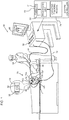
- Fig. 1 is a schematic, pictorial illustration of an electrode positioning system 20, according to embodiments of the present invention.
- a catheter 22 is inserted into a lumen, such as a chamber of a heart 24 of a subject 26 wherein a medical procedure, such as ablation of the heart tissue, is to be performed.
- a medical procedure such as ablation of the heart tissue
- a distal end 28 of the catheter there are one or more electrodes, and by way of example two electrodes 30, 32 are shown in the figure.
- at least one of the electrodes at the distal end herein assumed to be electrode 30 at the tip of the distal end, is used by system 20.
- each electrode at the distal end, including electrode 30, may perform multiple functions.
- the electrodes may be configured to perform ablation of tissue of the heart and/or to measure potentials of heart tissue.
- the distal end may comprise other elements; by way of example distal end 28 comprises a force sensor 36.
- SC 50 system controller
- processing unit 52 communicating with a memory 54, wherein is stored software for operation of system 20.
- Controller 50 is typically an industry-standard personal computer (PC) comprising a general-purpose computer processor. However, in some embodiments, at least some of the functions of the controller are performed using custom-designed hardware and software, such as an application specific integrated circuit (ASIC) or a field programmable gate array (FPGA).
- ASIC application specific integrated circuit
- FPGA field programmable gate array
- Controller 50 is typically operated by practitioner 34 using a pointing device 56 and a display 60, which enable the practitioner to set parameters of system 20. Display 60 typically also presents results of the procedure to the medical practitioner.
- the software in memory 54 may be downloaded to the controller in electronic form, over a network, for example.
- the software may be provided on non-transitory tangible media, such as optical, magnetic, or electronic storage media.
- a plurality of substantially similar body-surface electrodes 70 such as adhesive skin patches, and also referred to herein as patches 70, are coupled to the body-surface (i.e., the skin) of subject 26 in general proximity to heart 24.
- patches 70 are distinguished from each other by appending a letter to the identifying numeral 70 of the patches.
- a generic patch may be referred to as patch 70N.
- practitioner 34 may be able to identify individual patches 70, for example by the patches and/or their leads being color coded or marked with an identifying letter or number. A use by system 20 for such identification is described below.
- system controller 50 injects an alternating current into electrode 30, via cabling in catheter 22.
- the injected current returns to the system controller via patches 70, and via cabling 72 connecting the patches to the system controller.
- the system controller uses a catheter tracking module 74 the system controller analyzes the different alternating returning currents, and determines position coordinates of the distal tip in, or in proximity to, heart 24 based on the returning currents from each of patches 70.
- the system controller is able to show the location of the distal tip inside the heart on display 60.
- Such a location system measuring the location of the distal tip by measuring currents from the tip received by patches 70, is herein termed a current location system.
- U. S. Patent 8,456,182 to Bar-Tal et al. which is referenced above, describes such a system.
- patches 70 should surround the heart. As is described herein, system 20 determines positions for the patches so that the patches satisfy this geometrical relationship.
- the distal tip may also be tracked by other systems known in the art, for example, by a magnetic tracking system.
- a magnetic tracking system is the CARTO 3 system, produced by Biosense Webster, Inc, Diamond Bar, CA, which tracks the distal tip by using alternating magnetic fields to induce corresponding positioning currents in coils in the tip.
- the fields are typically set to alternate at frequencies of 1 - 3 kHz, but may be set to alternate at higher frequencies, up to 50 kHz or more.
- each of the patches also receives electrocardiograph (ECG) signals generated by heart 24, and the ECG signals are transferred by cabling 72 to system controller 50.
- ECG electrocardiograph
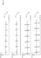
- the received ECG signals acquired by patches 70 are dependent on the locations of the patches with respect to heart 24, and vary significantly from location to location. Examples of typical ECG signals are illustrated in Fig. 2 below.
- Fig. 2 schematically illustrates graphs of ECG signals acquired by patches 70 in different locations on subject 26, according to an embodiment of the present invention. All graphs are assumed to be generated by heart 24 as it beats, so that although there are variations in the graphs, such as the shape of the acquired signals as well as phase differences between the signals, there are also consistent parameters, such as the period of the signals.
- the ECG signals are assumed to be unipolar signals, with the potential of the signals being measured with reference to an arbitrary reference, typically the Wilson central terminal (WCT) reference.
- WCT Wilson central terminal
- a graph 100 is assumed to correspond to the ECG signal acquired by patch 70A
- a graph 102 is assumed to correspond to the ECG signal acquired by patch 70C
- a graph 104 is assumed to correspond to the ECG signal acquired by patch 70D
- a graph 106 is assumed to correspond to the ECG signal acquired by patch 70F.
- Embodiments of the present invention process the ECG signals from each of patches 70 to generate respective signal parameters that are characteristic of the position of the patch acquiring the signal.
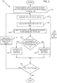
- Fig. 3 is a flowchart 150 of steps describing the processing of the ECG signals, and how the signal parameters are used to check if the arrangement of patches 70 satisfies a geometrical relationship between the patches and the heart
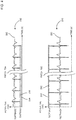
- Fig. 4 shows graphs illustrating some of the steps of the flowchart, according to an embodiment of the present invention. All the steps of the flowchart may typically be applied prior to the medical procedure referred to above being initiated, but in some embodiments the steps of the flowchart may be applied while the procedure is being performed.
- a first step 152 practitioner 34 attaches a group of N T patches 70 to the skin of the patient, where N T is the number of patches attached.
- Patches 70 are typically attached so that there is a predetermined separation between "nearest-neighbor" patches, the predetermined separation typically being in the range of 20 cm - 25 cm, although the separation may be larger or smaller than values in this range.
- N PRES may be considered to be a measure of an allowable variation between different types of patches in the group of patches, and acts as a condition limiter on the allowable variation, as is explained in more detail below.
- N PRES also referred to herein as the condition limiter number, is selected so that the following condition is valid: 1 ⁇ N PRES ⁇ N T where N T is as defined above, i.e., is the total number of patches in the group.
- steps 154 - 164 is written for the actions performed by controller 50 in analyzing the ECG signals acquired by patches 70A and 70C, it will be understood that the controller performs the actions for each patch in the group of patches 70.
- the controller acquires and stores respective sets of ECG signals from patch 70A and from patch 70C.
- Each set of ECG signals comprises a set of ordered pairs of the potential registered at the patch at a given time.
- the acquisition is over a preset period of time, for example 10s, so that approximately ten periods of the ECG signals are acquired.
- Typical graphs of the acquired signals are graphs 200 and 210, which are enlargements of respective graphs 100 and 104 ( Fig. 2 ).
- a baseline calculation step 156 the controller calculates an arithmetic average of the respective stored potentials of each set, and assumes that the average corresponds to the baseline of the respective signal.
- a broken line 220 illustrates the baseline potential 70A V BASE calculated for patch 70A
- a broken line 230 illustrates the baseline potential 70C V BASE calculated for patch 70C.
- the controller analyzes the stored signals to find the value of the maximum deviation of the stored potentials of each period of the signal from the baseline potential.
- the value of each maximum deviation occurs during the QRS complex of the ECG signals.
- the values of the maximum deviations lie within a relatively narrow range of values, which are different from each other because of inherent variations of the generated signals, as well as because of inherent noise in the signals.
- the controller averages the maximum deviations for each patch, to find mean maximum deviations.
- Graph 200 illustrates a mean maximum deviation 70A V MAX for patch 70A
- graph 210 illustrates a mean maximum deviation 70C V MAX for patch 70C.
- step 160 the controller determines if D 70N is positive, i.e., if D 70N ⁇ 0, or if the difference is negative, i.e., if D 70N ⁇ 0.
- a first polarity step 162 the controller assigns the polarity of the patch to be positive, and determines a number of positive polarity patches Np. If the difference is negative, then in a second polarity step 164 the controller assigns the polarity of the patch to be negative, and determines a number of negative polarity patches N N .
- the controller performs steps 154 - 164 for each of patches 70, and so determines a polarity for each of the patches.
- heart 24 may be considered to be a radiating dipole, with a dipole axis on a line between the right shoulder and the left leg. Such a dipole defines a surface that is orthogonal to the line, and that passes through a point on the line representing the position of the heart.
- the dipole radiation from the heart has a first phase
- the dipole radiation has a second phase that is 180° to the first phase.
- the polarity evaluated by controller 50 is a measure of the phase of the dipole signal radiated by the heart. Patches having the same polarity may thus be assumed to be on one side of the surface defined above; patches having opposite polarities may be assumed to be on opposite sides of the surface.
- a comparison step 166 the controller evaluates an absolute value of the difference between the number of positive polarity patches Np and the number of negative polarity patches N N .
- the absolute value provides an indication to the controller of the relative numbers of patches 70 on the two sides of the surface defined above, and in comparison step 166 the controller checks if the absolute value is less than or equal to the condition limiter number set in step 152. I.e., the controller checks if the following inequality is valid: N P ⁇ N N ⁇ N PRES
- a message may be shown on display 60 informing the practitioner that the patches are in valid locations, i.e., that they surround the heart and that the desired geometrical relationship has been achieved, and the flowchart ends.
- step 166 determines that the preset condition for comparison step 166 is invalid, then the flowchart continues to a move patch step 170, wherein at least one of the patches is moved and re-attached. From step 170 the flowchart returns to step 154 and the controller reiterates steps 154 - 166 for all patches in the group, until step 166 is valid.
- a message may be shown on display 60 informing the practitioner that the patches do not surround the heart and that at least one patch should be moved.
- controller 50 may incorporate into the message a suggestion for which patch or patches could be moved, so that the preset condition of step 166 becomes valid.
- N PRES acts as a condition limiter on an allowable variation between numbers of positive and negative patches.
- a small value for N PRES means that there is little allowable variation between the numbers of patches, a large value for N PRES means that the variation between the patch numbers is greater.
- Flowchart 150 may be used to evaluate if all attached patches, taken together as one group, satisfy a geometrical relationship. Alternatively or additionally, the flowchart may be used to evaluate if different sub-groups of attached patches satisfy respective geometrical relationships.
- N T 8 patches 70 in total attached to subject 26.
- N T 8 patches 70 in total attached to subject 26.
- N T 8 patches that N PRES may be, from equation (1), any whole number from 1 to 7.
- N PRES is set equal to 3
- the group of 8 patches 70 may, by way of example, be divided into a first sub-group of 5 patches 70 applied to the chest of subject 26, and a second sub-group of three patches 70 applied to the back of the subject.
- variables such as the numbers of patches in each sub-group are distinguished by prefacing the variable with an identifying sub-script.
- practitioner 34 may use any combination of the geometrical relationships, i.e., the comparisons of step 166, to check if an overall geometrical relationship for the patches has been achieved.
- the practitioner may require that the comparisons of all three geometrical relationships, i.e. for the whole group and both sub-groups, be valid.
- the practitioner may require that the comparisons of any two geometrical relationships, e.g. for both sub-groups be valid.
- the practitioner may require that the comparison of any one of the geometrical relationships, e.g. the chest sub-group or the whole group, be valid.
- comparison step 166 is valid if any three of the patches have positive polarities, and if the remaining three patches have negative polarities.
- the practitioner may require, as a relatively strict constraint in order to achieve the geometrical relationship, that the comparisons described above for the whole group and both sub-groups be valid.
- the practitioner may require that only the comparisons for the two sub-groups be valid.
- the analysis described above derives a signal parameter for each patch 70, the polarity, by processing the ECG signals from the respective patches.
- the controller uses the signal parameters to check that the patches are in a required geometrical relationship with respect to the heart, e.g., that they surround the heart.
- the polarity is a binary parameter, and those having ordinary skill in the art will be aware of other binary signal parameters that the controller may use to check that the geometrical relationship has been achieved.
- Such binary parameters include, but are not limited to, the amplitude of the ECG signal being greater than or less than a predetermined amplitude value, and the phase of the ECG signal being greater than or less than a predetermined phase value.
- the signal parameter derived from the ECG signals is not necessarily binary, and may be a non-binary parameter, such as a rational number.
- the binary polarity parameter described above assigns a binary value to the ECG signal, and its respective patch, according to whether the maximum deviation from the baseline is above or below the baseline.
- the binary value of the maximum deviation could be incorporated into the polarity, so forming a non-binary rational number that could be used in a condition for checking that a required geometrical relationship is valid.
Applications Claiming Priority (1)
| Application Number | Priority Date | Filing Date | Title |
|---|---|---|---|
| US14/253,209 US9326693B2 (en) | 2014-04-15 | 2014-04-15 | Placement of electrodes in proximity to the heart |
Publications (2)
| Publication Number | Publication Date |
|---|---|
| EP2932894A1 EP2932894A1 (en) | 2015-10-21 |
| EP2932894B1 true EP2932894B1 (en) | 2017-03-08 |
Family
ID=52875029
Family Applications (1)
| Application Number | Title | Priority Date | Filing Date |
|---|---|---|---|
| EP15163531.5A Active EP2932894B1 (en) | 2014-04-15 | 2015-04-14 | Placement of electrodes in proximity to the heart |
Country Status (7)
| Country | Link |
|---|---|
| US (1) | US9326693B2 (ja) |
| EP (1) | EP2932894B1 (ja) |
| JP (1) | JP6599122B2 (ja) |
| CN (2) | CN111466904B (ja) |
| AU (1) | AU2015201646B2 (ja) |
| CA (1) | CA2888033A1 (ja) |
| IL (1) | IL237705B (ja) |
Families Citing this family (7)
| Publication number | Priority date | Publication date | Assignee | Title |
|---|---|---|---|---|
| US9326693B2 (en) * | 2014-04-15 | 2016-05-03 | Biosense Webster (Israel) Ltd. | Placement of electrodes in proximity to the heart |
| US20170219509A1 (en) * | 2016-02-03 | 2017-08-03 | Draeger Medical Systems, Inc. | Determining Electrophysiological Electrode Quality |
| WO2018043692A1 (ja) * | 2016-09-05 | 2018-03-08 | 日本電気株式会社 | 血圧測定装置、血圧測定方法及び血圧測定プログラムを記録した記録媒体 |
| EP3612081A1 (en) * | 2017-04-18 | 2020-02-26 | Boston Scientific Scimed Inc. | Annotation histogram for electrophysiological signals |
| US10492704B2 (en) * | 2017-08-29 | 2019-12-03 | Biosense Webster (Israel) Ltd. | Medical patch for simultaneously sensing ECG signals and impedance-indicative electrical signals |
| CN109674463A (zh) * | 2017-10-19 | 2019-04-26 | 上海西门子医疗器械有限公司 | 判断心电导联错接的方法和装置 |
| US11364073B2 (en) * | 2019-02-20 | 2022-06-21 | Biosense Webster (Israel) Ltd. | Cardiac map segmentation |
Family Cites Families (21)
| Publication number | Priority date | Publication date | Assignee | Title |
|---|---|---|---|---|
| US4692148A (en) | 1986-03-28 | 1987-09-08 | Aisin Seiki Kabushiki Kaisha | Intra-aortic balloon pump apparatus and method of using same |
| US4909261A (en) | 1989-02-13 | 1990-03-20 | Syracuse University | Tracking multielectrode electroglottograph |
| US6128526A (en) * | 1999-03-29 | 2000-10-03 | Medtronic, Inc. | Method for ischemia detection and apparatus for using same |
| US6282440B1 (en) * | 1999-12-31 | 2001-08-28 | Ge Marquette Medical Systems, Inc. | Method to identify electrode placement |
| US7001383B2 (en) * | 2002-10-21 | 2006-02-21 | Biosense, Inc. | Real-time monitoring and mapping of ablation lesion formation in the heart |
| US20050137483A1 (en) * | 2003-12-22 | 2005-06-23 | Fischell Robert E. | Electrogram signal filtering in systems for detecting ischemia |
| US7536218B2 (en) | 2005-07-15 | 2009-05-19 | Biosense Webster, Inc. | Hybrid magnetic-based and impedance-based position sensing |
| US8948885B2 (en) * | 2007-11-08 | 2015-02-03 | Koninklijke Philips N.V. | Repositionable electrode and systems and methods for identifying electrode position for cardiotherapy |
| US8494608B2 (en) * | 2008-04-18 | 2013-07-23 | Medtronic, Inc. | Method and apparatus for mapping a structure |
| JP5224961B2 (ja) * | 2008-07-31 | 2013-07-03 | パナソニック株式会社 | 分析用デバイスと分析方法 |
| US8456182B2 (en) * | 2008-09-30 | 2013-06-04 | Biosense Webster, Inc. | Current localization tracker |
| EP2429390B1 (en) | 2009-05-15 | 2015-09-09 | Nox Medical | System and methods using flexible capacitive electrodes for measuring biosignals |
| US9532724B2 (en) | 2009-06-12 | 2017-01-03 | Bard Access Systems, Inc. | Apparatus and method for catheter navigation using endovascular energy mapping |
| JP5642184B2 (ja) | 2009-09-14 | 2014-12-17 | コーニンクレッカ フィリップス エヌ ヴェ | Mpiを用いた非侵襲的心臓内心電図検査法のための装置及びその作動方法 |
| US9277872B2 (en) * | 2011-01-13 | 2016-03-08 | Rhythmia Medical, Inc. | Electroanatomical mapping |
| US8892181B2 (en) * | 2011-10-21 | 2014-11-18 | Mindchild Medical, Inc. | Non-invasive fetal monitoring |
| KR101912090B1 (ko) | 2012-02-08 | 2018-10-26 | 삼성전자 주식회사 | 심방세동 예측 모델 생성장치 및 방법과, 심방세동 예측장치 및 방법 |
| US9402556B2 (en) * | 2012-06-11 | 2016-08-02 | Biosense Webster (Israel) Ltd. | Compensation for heart movement in a body coordinate system |
| US8577450B1 (en) * | 2012-07-23 | 2013-11-05 | Biosense Webster (Israel) Ltd. | Graphic interface for multi-spine probe |
| GB2510452A (en) * | 2013-01-31 | 2014-08-06 | Naviconix Ltd | Method of mapping the heart with a trackable electrode catheter |
| US9326693B2 (en) * | 2014-04-15 | 2016-05-03 | Biosense Webster (Israel) Ltd. | Placement of electrodes in proximity to the heart |
-
2014
- 2014-04-15 US US14/253,209 patent/US9326693B2/en active Active
-
2015
- 2015-03-12 IL IL237705A patent/IL237705B/en active IP Right Grant
- 2015-03-31 AU AU2015201646A patent/AU2015201646B2/en not_active Ceased
- 2015-04-14 EP EP15163531.5A patent/EP2932894B1/en active Active
- 2015-04-14 JP JP2015082350A patent/JP6599122B2/ja active Active
- 2015-04-14 CA CA2888033A patent/CA2888033A1/en not_active Abandoned
- 2015-04-15 CN CN202010230342.8A patent/CN111466904B/zh active Active
- 2015-04-15 CN CN201510178160.XA patent/CN105030226B/zh active Active
Non-Patent Citations (1)
| Title |
|---|
| None * |
Also Published As
| Publication number | Publication date |
|---|---|
| AU2015201646B2 (en) | 2019-04-18 |
| AU2015201646A1 (en) | 2015-10-29 |
| JP6599122B2 (ja) | 2019-10-30 |
| JP2015202412A (ja) | 2015-11-16 |
| CN105030226B (zh) | 2020-02-21 |
| CN105030226A (zh) | 2015-11-11 |
| CA2888033A1 (en) | 2015-10-15 |
| IL237705B (en) | 2018-08-30 |
| EP2932894A1 (en) | 2015-10-21 |
| CN111466904B (zh) | 2023-07-25 |
| US20150289776A1 (en) | 2015-10-15 |
| CN111466904A (zh) | 2020-07-31 |
| US9326693B2 (en) | 2016-05-03 |
Similar Documents
| Publication | Publication Date | Title |
|---|---|---|
| EP2932894B1 (en) | Placement of electrodes in proximity to the heart | |
| US11596324B2 (en) | Combined active current location (ACL) and tissue proximity indication (TPI) system | |
| US20180296114A1 (en) | Localization system and method useful in the acquisition and analysis of cardiac information | |
| CN107530018A (zh) | 用于方向独立感测的系统和方法 | |
| US9974462B2 (en) | Signal characterization for detecting and/or analyzing driver activity | |
| WO2015120064A1 (en) | Integrated analysis of electrophysiological data | |
| EP3797689A1 (en) | Intracardiac electrocardiogram presentation | |
| EP2632330B1 (en) | Electrophysiological mapping system using external electrodes | |
| JP7080650B2 (ja) | ブルガダ症候群を排除するためのecg信号の解析及びマッピング並びにアブレーション点の決定 | |
| JP2018534035A (ja) | 心臓再分極をマッピングするための方法及びシステム | |
| JP2020089730A (ja) | 冠状静脈洞(cs)カテーテルの移動検出 | |
| JP2020523106A (ja) | 生体インピーダンス測定のための電極のスペーシング | |
| EP3656301B1 (en) | Compensating for artifacts while tracking an intrabody probe | |
| US11844602B2 (en) | Impedance-enriched electrophysiological measurements | |
| US20210260337A1 (en) | Detection of catheter location, orientation, and movement direction | |
| EP3666181A1 (en) | Display of arrhythmia type |
Legal Events
| Date | Code | Title | Description |
|---|---|---|---|
| PUAI | Public reference made under article 153(3) epc to a published international application that has entered the european phase |
Free format text: ORIGINAL CODE: 0009012 |
|
| AK | Designated contracting states |
Kind code of ref document: A1 Designated state(s): AL AT BE BG CH CY CZ DE DK EE ES FI FR GB GR HR HU IE IS IT LI LT LU LV MC MK MT NL NO PL PT RO RS SE SI SK SM TR |
|
| AX | Request for extension of the european patent |
Extension state: BA ME |
|
| 17P | Request for examination filed |
Effective date: 20160418 |
|
| RBV | Designated contracting states (corrected) |
Designated state(s): AL AT BE BG CH CY CZ DE DK EE ES FI FR GB GR HR HU IE IS IT LI LT LU LV MC MK MT NL NO PL PT RO RS SE SI SK SM TR |
|
| GRAP | Despatch of communication of intention to grant a patent |
Free format text: ORIGINAL CODE: EPIDOSNIGR1 |
|
| RIC1 | Information provided on ipc code assigned before grant |
Ipc: A61B 5/06 20060101ALI20160919BHEP Ipc: A61B 5/0408 20060101AFI20160919BHEP |
|
| INTG | Intention to grant announced |
Effective date: 20161018 |
|
| GRAS | Grant fee paid |
Free format text: ORIGINAL CODE: EPIDOSNIGR3 |
|
| GRAA | (expected) grant |
Free format text: ORIGINAL CODE: 0009210 |
|
| RAP1 | Party data changed (applicant data changed or rights of an application transferred) |
Owner name: BIOSENSE WEBSTER (ISRAEL) LTD. |
|
| AK | Designated contracting states |
Kind code of ref document: B1 Designated state(s): AL AT BE BG CH CY CZ DE DK EE ES FI FR GB GR HR HU IE IS IT LI LT LU LV MC MK MT NL NO PL PT RO RS SE SI SK SM TR |
|
| REG | Reference to a national code |
Ref country code: GB Ref legal event code: FG4D |
|
| REG | Reference to a national code |
Ref country code: FR Ref legal event code: PLFP Year of fee payment: 3 |
|
| REG | Reference to a national code |
Ref country code: CH Ref legal event code: EP Ref country code: AT Ref legal event code: REF Ref document number: 872780 Country of ref document: AT Kind code of ref document: T Effective date: 20170315 |
|
| REG | Reference to a national code |
Ref country code: IE Ref legal event code: FG4D |
|
| REG | Reference to a national code |
Ref country code: DE Ref legal event code: R096 Ref document number: 602015001706 Country of ref document: DE |
|
| REG | Reference to a national code |
Ref country code: NL Ref legal event code: FP |
|
| REG | Reference to a national code |
Ref country code: LT Ref legal event code: MG4D |
|
| PG25 | Lapsed in a contracting state [announced via postgrant information from national office to epo] |
Ref country code: NO Free format text: LAPSE BECAUSE OF FAILURE TO SUBMIT A TRANSLATION OF THE DESCRIPTION OR TO PAY THE FEE WITHIN THE PRESCRIBED TIME-LIMIT Effective date: 20170608 Ref country code: HR Free format text: LAPSE BECAUSE OF FAILURE TO SUBMIT A TRANSLATION OF THE DESCRIPTION OR TO PAY THE FEE WITHIN THE PRESCRIBED TIME-LIMIT Effective date: 20170308 Ref country code: GR Free format text: LAPSE BECAUSE OF FAILURE TO SUBMIT A TRANSLATION OF THE DESCRIPTION OR TO PAY THE FEE WITHIN THE PRESCRIBED TIME-LIMIT Effective date: 20170609 Ref country code: FI Free format text: LAPSE BECAUSE OF FAILURE TO SUBMIT A TRANSLATION OF THE DESCRIPTION OR TO PAY THE FEE WITHIN THE PRESCRIBED TIME-LIMIT Effective date: 20170308 Ref country code: LT Free format text: LAPSE BECAUSE OF FAILURE TO SUBMIT A TRANSLATION OF THE DESCRIPTION OR TO PAY THE FEE WITHIN THE PRESCRIBED TIME-LIMIT Effective date: 20170308 |
|
| REG | Reference to a national code |
Ref country code: AT Ref legal event code: MK05 Ref document number: 872780 Country of ref document: AT Kind code of ref document: T Effective date: 20170308 |
|
| PG25 | Lapsed in a contracting state [announced via postgrant information from national office to epo] |
Ref country code: SE Free format text: LAPSE BECAUSE OF FAILURE TO SUBMIT A TRANSLATION OF THE DESCRIPTION OR TO PAY THE FEE WITHIN THE PRESCRIBED TIME-LIMIT Effective date: 20170308 Ref country code: BG Free format text: LAPSE BECAUSE OF FAILURE TO SUBMIT A TRANSLATION OF THE DESCRIPTION OR TO PAY THE FEE WITHIN THE PRESCRIBED TIME-LIMIT Effective date: 20170608 Ref country code: ES Free format text: LAPSE BECAUSE OF FAILURE TO SUBMIT A TRANSLATION OF THE DESCRIPTION OR TO PAY THE FEE WITHIN THE PRESCRIBED TIME-LIMIT Effective date: 20170308 Ref country code: RS Free format text: LAPSE BECAUSE OF FAILURE TO SUBMIT A TRANSLATION OF THE DESCRIPTION OR TO PAY THE FEE WITHIN THE PRESCRIBED TIME-LIMIT Effective date: 20170308 Ref country code: LV Free format text: LAPSE BECAUSE OF FAILURE TO SUBMIT A TRANSLATION OF THE DESCRIPTION OR TO PAY THE FEE WITHIN THE PRESCRIBED TIME-LIMIT Effective date: 20170308 |
|
| PG25 | Lapsed in a contracting state [announced via postgrant information from national office to epo] |
Ref country code: RO Free format text: LAPSE BECAUSE OF FAILURE TO SUBMIT A TRANSLATION OF THE DESCRIPTION OR TO PAY THE FEE WITHIN THE PRESCRIBED TIME-LIMIT Effective date: 20170308 Ref country code: AT Free format text: LAPSE BECAUSE OF FAILURE TO SUBMIT A TRANSLATION OF THE DESCRIPTION OR TO PAY THE FEE WITHIN THE PRESCRIBED TIME-LIMIT Effective date: 20170308 Ref country code: SK Free format text: LAPSE BECAUSE OF FAILURE TO SUBMIT A TRANSLATION OF THE DESCRIPTION OR TO PAY THE FEE WITHIN THE PRESCRIBED TIME-LIMIT Effective date: 20170308 Ref country code: CZ Free format text: LAPSE BECAUSE OF FAILURE TO SUBMIT A TRANSLATION OF THE DESCRIPTION OR TO PAY THE FEE WITHIN THE PRESCRIBED TIME-LIMIT Effective date: 20170308 Ref country code: EE Free format text: LAPSE BECAUSE OF FAILURE TO SUBMIT A TRANSLATION OF THE DESCRIPTION OR TO PAY THE FEE WITHIN THE PRESCRIBED TIME-LIMIT Effective date: 20170308 |
|
| PG25 | Lapsed in a contracting state [announced via postgrant information from national office to epo] |
Ref country code: SM Free format text: LAPSE BECAUSE OF FAILURE TO SUBMIT A TRANSLATION OF THE DESCRIPTION OR TO PAY THE FEE WITHIN THE PRESCRIBED TIME-LIMIT Effective date: 20170308 Ref country code: PL Free format text: LAPSE BECAUSE OF FAILURE TO SUBMIT A TRANSLATION OF THE DESCRIPTION OR TO PAY THE FEE WITHIN THE PRESCRIBED TIME-LIMIT Effective date: 20170308 Ref country code: IS Free format text: LAPSE BECAUSE OF FAILURE TO SUBMIT A TRANSLATION OF THE DESCRIPTION OR TO PAY THE FEE WITHIN THE PRESCRIBED TIME-LIMIT Effective date: 20170708 Ref country code: PT Free format text: LAPSE BECAUSE OF FAILURE TO SUBMIT A TRANSLATION OF THE DESCRIPTION OR TO PAY THE FEE WITHIN THE PRESCRIBED TIME-LIMIT Effective date: 20170710 |
|
| REG | Reference to a national code |
Ref country code: DE Ref legal event code: R097 Ref document number: 602015001706 Country of ref document: DE |
|
| PLBE | No opposition filed within time limit |
Free format text: ORIGINAL CODE: 0009261 |
|
| STAA | Information on the status of an ep patent application or granted ep patent |
Free format text: STATUS: NO OPPOSITION FILED WITHIN TIME LIMIT |
|
| REG | Reference to a national code |
Ref country code: IE Ref legal event code: MM4A |
|
| PG25 | Lapsed in a contracting state [announced via postgrant information from national office to epo] |
Ref country code: DK Free format text: LAPSE BECAUSE OF FAILURE TO SUBMIT A TRANSLATION OF THE DESCRIPTION OR TO PAY THE FEE WITHIN THE PRESCRIBED TIME-LIMIT Effective date: 20170308 Ref country code: MC Free format text: LAPSE BECAUSE OF FAILURE TO SUBMIT A TRANSLATION OF THE DESCRIPTION OR TO PAY THE FEE WITHIN THE PRESCRIBED TIME-LIMIT Effective date: 20170308 |
|
| 26N | No opposition filed |
Effective date: 20171211 |
|
| PG25 | Lapsed in a contracting state [announced via postgrant information from national office to epo] |
Ref country code: LU Free format text: LAPSE BECAUSE OF NON-PAYMENT OF DUE FEES Effective date: 20170414 Ref country code: SI Free format text: LAPSE BECAUSE OF FAILURE TO SUBMIT A TRANSLATION OF THE DESCRIPTION OR TO PAY THE FEE WITHIN THE PRESCRIBED TIME-LIMIT Effective date: 20170308 |
|
| REG | Reference to a national code |
Ref country code: FR Ref legal event code: PLFP Year of fee payment: 4 |
|
| PG25 | Lapsed in a contracting state [announced via postgrant information from national office to epo] |
Ref country code: IE Free format text: LAPSE BECAUSE OF NON-PAYMENT OF DUE FEES Effective date: 20170414 |
|
| PG25 | Lapsed in a contracting state [announced via postgrant information from national office to epo] |
Ref country code: MT Free format text: LAPSE BECAUSE OF NON-PAYMENT OF DUE FEES Effective date: 20170414 |
|
| REG | Reference to a national code |
Ref country code: CH Ref legal event code: PL |
|
| PG25 | Lapsed in a contracting state [announced via postgrant information from national office to epo] |
Ref country code: LI Free format text: LAPSE BECAUSE OF NON-PAYMENT OF DUE FEES Effective date: 20180430 Ref country code: CH Free format text: LAPSE BECAUSE OF NON-PAYMENT OF DUE FEES Effective date: 20180430 |
|
| PGFP | Annual fee paid to national office [announced via postgrant information from national office to epo] |
Ref country code: BE Payment date: 20190315 Year of fee payment: 5 |
|
| PG25 | Lapsed in a contracting state [announced via postgrant information from national office to epo] |
Ref country code: HU Free format text: LAPSE BECAUSE OF FAILURE TO SUBMIT A TRANSLATION OF THE DESCRIPTION OR TO PAY THE FEE WITHIN THE PRESCRIBED TIME-LIMIT; INVALID AB INITIO Effective date: 20150414 |
|
| PG25 | Lapsed in a contracting state [announced via postgrant information from national office to epo] |
Ref country code: CY Free format text: LAPSE BECAUSE OF FAILURE TO SUBMIT A TRANSLATION OF THE DESCRIPTION OR TO PAY THE FEE WITHIN THE PRESCRIBED TIME-LIMIT Effective date: 20170308 |
|
| PG25 | Lapsed in a contracting state [announced via postgrant information from national office to epo] |
Ref country code: MK Free format text: LAPSE BECAUSE OF FAILURE TO SUBMIT A TRANSLATION OF THE DESCRIPTION OR TO PAY THE FEE WITHIN THE PRESCRIBED TIME-LIMIT Effective date: 20170308 |
|
| PG25 | Lapsed in a contracting state [announced via postgrant information from national office to epo] |
Ref country code: TR Free format text: LAPSE BECAUSE OF FAILURE TO SUBMIT A TRANSLATION OF THE DESCRIPTION OR TO PAY THE FEE WITHIN THE PRESCRIBED TIME-LIMIT Effective date: 20170308 |
|
| PG25 | Lapsed in a contracting state [announced via postgrant information from national office to epo] |
Ref country code: AL Free format text: LAPSE BECAUSE OF FAILURE TO SUBMIT A TRANSLATION OF THE DESCRIPTION OR TO PAY THE FEE WITHIN THE PRESCRIBED TIME-LIMIT Effective date: 20170308 |
|
| REG | Reference to a national code |
Ref country code: DE Ref legal event code: R079 Ref document number: 602015001706 Country of ref document: DE Free format text: PREVIOUS MAIN CLASS: A61B0005040800 Ipc: A61B0005280000 |
|
| REG | Reference to a national code |
Ref country code: BE Ref legal event code: MM Effective date: 20200430 |
|
| PG25 | Lapsed in a contracting state [announced via postgrant information from national office to epo] |
Ref country code: BE Free format text: LAPSE BECAUSE OF NON-PAYMENT OF DUE FEES Effective date: 20200430 |
|
| PGFP | Annual fee paid to national office [announced via postgrant information from national office to epo] |
Ref country code: FR Payment date: 20230309 Year of fee payment: 9 |
|
| PGFP | Annual fee paid to national office [announced via postgrant information from national office to epo] |
Ref country code: IT Payment date: 20230310 Year of fee payment: 9 |
|
| PGFP | Annual fee paid to national office [announced via postgrant information from national office to epo] |
Ref country code: NL Payment date: 20230314 Year of fee payment: 9 |
|
| PGFP | Annual fee paid to national office [announced via postgrant information from national office to epo] |
Ref country code: DE Payment date: 20230228 Year of fee payment: 9 |
|
| PGFP | Annual fee paid to national office [announced via postgrant information from national office to epo] |
Ref country code: GB Payment date: 20240229 Year of fee payment: 10 |