EP2932128B1 - Doppelschaltkupplung mit zwei kraftschlüssig wirksamen kupplungseinheiten - Google Patents
Doppelschaltkupplung mit zwei kraftschlüssig wirksamen kupplungseinheiten Download PDFInfo
- Publication number
- EP2932128B1 EP2932128B1 EP13805841.7A EP13805841A EP2932128B1 EP 2932128 B1 EP2932128 B1 EP 2932128B1 EP 13805841 A EP13805841 A EP 13805841A EP 2932128 B1 EP2932128 B1 EP 2932128B1
- Authority
- EP
- European Patent Office
- Prior art keywords
- clutch
- carrier ring
- pressure disk
- axially
- dual clutch
- Prior art date
- Legal status (The legal status is an assumption and is not a legal conclusion. Google has not performed a legal analysis and makes no representation as to the accuracy of the status listed.)
- Active
Links
Images

Classifications
-
- F—MECHANICAL ENGINEERING; LIGHTING; HEATING; WEAPONS; BLASTING
- F16—ENGINEERING ELEMENTS AND UNITS; GENERAL MEASURES FOR PRODUCING AND MAINTAINING EFFECTIVE FUNCTIONING OF MACHINES OR INSTALLATIONS; THERMAL INSULATION IN GENERAL
- F16D—COUPLINGS FOR TRANSMITTING ROTATION; CLUTCHES; BRAKES
- F16D21/00—Systems comprising a plurality of actuated clutches
- F16D21/02—Systems comprising a plurality of actuated clutches for interconnecting three or more shafts or other transmission members in different ways
- F16D21/06—Systems comprising a plurality of actuated clutches for interconnecting three or more shafts or other transmission members in different ways at least two driving shafts or two driven shafts being concentric
-
- F—MECHANICAL ENGINEERING; LIGHTING; HEATING; WEAPONS; BLASTING
- F16—ENGINEERING ELEMENTS AND UNITS; GENERAL MEASURES FOR PRODUCING AND MAINTAINING EFFECTIVE FUNCTIONING OF MACHINES OR INSTALLATIONS; THERMAL INSULATION IN GENERAL
- F16D—COUPLINGS FOR TRANSMITTING ROTATION; CLUTCHES; BRAKES
- F16D13/00—Friction clutches
- F16D13/58—Details
- F16D13/60—Clutching elements
- F16D13/64—Clutch-plates; Clutch-lamellae
- F16D13/69—Arrangements for spreading lamellae in the released state
-
- F—MECHANICAL ENGINEERING; LIGHTING; HEATING; WEAPONS; BLASTING
- F16—ENGINEERING ELEMENTS AND UNITS; GENERAL MEASURES FOR PRODUCING AND MAINTAINING EFFECTIVE FUNCTIONING OF MACHINES OR INSTALLATIONS; THERMAL INSULATION IN GENERAL
- F16D—COUPLINGS FOR TRANSMITTING ROTATION; CLUTCHES; BRAKES
- F16D13/00—Friction clutches
- F16D13/22—Friction clutches with axially-movable clutching members
- F16D13/38—Friction clutches with axially-movable clutching members with flat clutching surfaces, e.g. discs
- F16D13/52—Clutches with multiple lamellae ; Clutches in which three or more axially moveable members are fixed alternately to the shafts to be coupled and are pressed from one side towards an axially-located member
-
- F—MECHANICAL ENGINEERING; LIGHTING; HEATING; WEAPONS; BLASTING
- F16—ENGINEERING ELEMENTS AND UNITS; GENERAL MEASURES FOR PRODUCING AND MAINTAINING EFFECTIVE FUNCTIONING OF MACHINES OR INSTALLATIONS; THERMAL INSULATION IN GENERAL
- F16D—COUPLINGS FOR TRANSMITTING ROTATION; CLUTCHES; BRAKES
- F16D13/00—Friction clutches
- F16D13/58—Details
- F16D13/70—Pressure members, e.g. pressure plates, for clutch-plates or lamellae; Guiding arrangements for pressure members
-
- F—MECHANICAL ENGINEERING; LIGHTING; HEATING; WEAPONS; BLASTING
- F16—ENGINEERING ELEMENTS AND UNITS; GENERAL MEASURES FOR PRODUCING AND MAINTAINING EFFECTIVE FUNCTIONING OF MACHINES OR INSTALLATIONS; THERMAL INSULATION IN GENERAL
- F16D—COUPLINGS FOR TRANSMITTING ROTATION; CLUTCHES; BRAKES
- F16D25/00—Fluid-actuated clutches
- F16D25/06—Fluid-actuated clutches in which the fluid actuates a piston incorporated in, i.e. rotating with the clutch
- F16D25/062—Fluid-actuated clutches in which the fluid actuates a piston incorporated in, i.e. rotating with the clutch the clutch having friction surfaces
- F16D25/063—Fluid-actuated clutches in which the fluid actuates a piston incorporated in, i.e. rotating with the clutch the clutch having friction surfaces with clutch members exclusively moving axially
- F16D25/0635—Fluid-actuated clutches in which the fluid actuates a piston incorporated in, i.e. rotating with the clutch the clutch having friction surfaces with clutch members exclusively moving axially with flat friction surfaces, e.g. discs
- F16D25/0638—Fluid-actuated clutches in which the fluid actuates a piston incorporated in, i.e. rotating with the clutch the clutch having friction surfaces with clutch members exclusively moving axially with flat friction surfaces, e.g. discs with more than two discs, e.g. multiple lamellae
-
- F—MECHANICAL ENGINEERING; LIGHTING; HEATING; WEAPONS; BLASTING
- F16—ENGINEERING ELEMENTS AND UNITS; GENERAL MEASURES FOR PRODUCING AND MAINTAINING EFFECTIVE FUNCTIONING OF MACHINES OR INSTALLATIONS; THERMAL INSULATION IN GENERAL
- F16D—COUPLINGS FOR TRANSMITTING ROTATION; CLUTCHES; BRAKES
- F16D25/00—Fluid-actuated clutches
- F16D25/10—Clutch systems with a plurality of fluid-actuated clutches
-
- F—MECHANICAL ENGINEERING; LIGHTING; HEATING; WEAPONS; BLASTING
- F16—ENGINEERING ELEMENTS AND UNITS; GENERAL MEASURES FOR PRODUCING AND MAINTAINING EFFECTIVE FUNCTIONING OF MACHINES OR INSTALLATIONS; THERMAL INSULATION IN GENERAL
- F16D—COUPLINGS FOR TRANSMITTING ROTATION; CLUTCHES; BRAKES
- F16D21/00—Systems comprising a plurality of actuated clutches
- F16D21/02—Systems comprising a plurality of actuated clutches for interconnecting three or more shafts or other transmission members in different ways
- F16D21/06—Systems comprising a plurality of actuated clutches for interconnecting three or more shafts or other transmission members in different ways at least two driving shafts or two driven shafts being concentric
- F16D2021/0607—Double clutch with torque input plate in-between the two clutches, i.e. having a central input plate
-
- F—MECHANICAL ENGINEERING; LIGHTING; HEATING; WEAPONS; BLASTING
- F16—ENGINEERING ELEMENTS AND UNITS; GENERAL MEASURES FOR PRODUCING AND MAINTAINING EFFECTIVE FUNCTIONING OF MACHINES OR INSTALLATIONS; THERMAL INSULATION IN GENERAL
- F16D—COUPLINGS FOR TRANSMITTING ROTATION; CLUTCHES; BRAKES
- F16D21/00—Systems comprising a plurality of actuated clutches
- F16D21/02—Systems comprising a plurality of actuated clutches for interconnecting three or more shafts or other transmission members in different ways
- F16D21/06—Systems comprising a plurality of actuated clutches for interconnecting three or more shafts or other transmission members in different ways at least two driving shafts or two driven shafts being concentric
- F16D2021/0661—Hydraulically actuated multiple lamellae clutches
-
- F—MECHANICAL ENGINEERING; LIGHTING; HEATING; WEAPONS; BLASTING
- F16—ENGINEERING ELEMENTS AND UNITS; GENERAL MEASURES FOR PRODUCING AND MAINTAINING EFFECTIVE FUNCTIONING OF MACHINES OR INSTALLATIONS; THERMAL INSULATION IN GENERAL
- F16D—COUPLINGS FOR TRANSMITTING ROTATION; CLUTCHES; BRAKES
- F16D21/00—Systems comprising a plurality of actuated clutches
- F16D21/02—Systems comprising a plurality of actuated clutches for interconnecting three or more shafts or other transmission members in different ways
- F16D21/06—Systems comprising a plurality of actuated clutches for interconnecting three or more shafts or other transmission members in different ways at least two driving shafts or two driven shafts being concentric
- F16D2021/0676—Mechanically actuated multiple lamellae clutches
-
- F—MECHANICAL ENGINEERING; LIGHTING; HEATING; WEAPONS; BLASTING
- F16—ENGINEERING ELEMENTS AND UNITS; GENERAL MEASURES FOR PRODUCING AND MAINTAINING EFFECTIVE FUNCTIONING OF MACHINES OR INSTALLATIONS; THERMAL INSULATION IN GENERAL
- F16D—COUPLINGS FOR TRANSMITTING ROTATION; CLUTCHES; BRAKES
- F16D21/00—Systems comprising a plurality of actuated clutches
- F16D21/02—Systems comprising a plurality of actuated clutches for interconnecting three or more shafts or other transmission members in different ways
- F16D21/06—Systems comprising a plurality of actuated clutches for interconnecting three or more shafts or other transmission members in different ways at least two driving shafts or two driven shafts being concentric
- F16D2021/0692—Systems comprising a plurality of actuated clutches for interconnecting three or more shafts or other transmission members in different ways at least two driving shafts or two driven shafts being concentric with two clutches arranged axially without radial overlap
-
- F—MECHANICAL ENGINEERING; LIGHTING; HEATING; WEAPONS; BLASTING
- F16—ENGINEERING ELEMENTS AND UNITS; GENERAL MEASURES FOR PRODUCING AND MAINTAINING EFFECTIVE FUNCTIONING OF MACHINES OR INSTALLATIONS; THERMAL INSULATION IN GENERAL
- F16D—COUPLINGS FOR TRANSMITTING ROTATION; CLUTCHES; BRAKES
- F16D2300/00—Special features for couplings or clutches
- F16D2300/12—Mounting or assembling
-
- F—MECHANICAL ENGINEERING; LIGHTING; HEATING; WEAPONS; BLASTING
- F16—ENGINEERING ELEMENTS AND UNITS; GENERAL MEASURES FOR PRODUCING AND MAINTAINING EFFECTIVE FUNCTIONING OF MACHINES OR INSTALLATIONS; THERMAL INSULATION IN GENERAL
- F16D—COUPLINGS FOR TRANSMITTING ROTATION; CLUTCHES; BRAKES
- F16D2300/00—Special features for couplings or clutches
- F16D2300/14—Clutches which are normally open, i.e. not engaged in released state
Definitions
- the invention relates to a double clutch with two frictionally effective clutch units, which are mounted on a common clutch hub - related to a clutch axis of rotation - non-rotatably and axially movably, as well as with a multi-part pressure disk arrangement axially fixed between the clutch units on the clutch hub, and with two axially movable ones Pressure pistons which can each be lifted by means of a pressure spring arrangement positioned in the clutch hub, each recess being made in the clutch hub as an axially extending blind hole.
- Such a double clutch is published from a catalog no. D 228 from Stromag AG with the date 01.1999 and is known as document XP-002662055.
- the known double clutch has two disk packs which are rotatably and axially movably mounted on a common clutch hub.
- the two disk packs are separated from one another by a pressure disk arrangement which sits on the outside of the clutch hub and is axially secured on the clutch hub.
- the two disk packs can each be acted upon by an axially movable pressure piston, which can be transferred into a release position for the disk packs by means of a compression spring arrangement positioned in the clutch hub.
- a thrust washer arrangement is arranged axially between two disk packs.
- the pressure disk arrangement is received in an outwardly open radial groove in the clutch hub.
- Corresponding compression springs of the compression spring assemblies for releasing the pressure pistons are supported on the pressure disk assembly.
- the corresponding recesses in opposing compression springs in the clutch hub are aligned coaxially to one another and are each implemented by a common bore that is continuous over the entire length of the clutch hub.
- the thrust washer arrangement is constructed in three parts from two thrust washer sections adjoining one another in the circumferential direction and a carrier ring to which the thrust washer sections are axially connected.
- the object of the invention is to create a double clutch of the type mentioned at the outset which enables dismantling and reassembly.
- the pressure disk arrangement is received in a radial groove of the clutch hub which - in relation to the clutch axis of rotation - is spaced radially and / or axially from the blind holes.
- the thrust washer arrangement has at least two thrust washer sections adjoining one another in the circumferential direction and a one-piece carrier ring to which the thrust washer sections are connected.
- each thrust washer section has, radially on the inside, an axially extending shoulder on which the carrier ring attaches radially outwards.
- An axial extension of the shoulder preferably corresponds to an axial thickness of the carrier ring.
- the carrier ring is preferably always slightly thicker than the axial extension of the shoulder.
- a radial distance between the shoulder and a radially outer edge of the respective thrust washer section corresponds to a radial extension of the carrier ring.
- the radial extent of the carrier ring corresponds at least largely to a radial extent of an effective contact surface of the adjacent coupling unit.
- a disk pack composed of several inner and outer disks is preferably provided as the coupling unit. Both the carrier ring opposite the adjacent coupling unit and an end face of the at least two pressure disk sections facing the other coupling unit form correspondingly planar and radially one-piece continuous contact surfaces.
- the carrier ring is also supported radially inwards and rests precisely against the thrust washer sections, so that outer surfaces of the carrier ring are flush with the corresponding outer contours of the thrust washer sections.
- the thrust washer sections lie and the carrier ring to one another in a particularly compact and packet-shaped manner, so that at most slight elastic deformations occur between the carrier ring and the thrust washer sections in the clutch operation.
- the thrust washer sections and the carrier ring lie flat against one another in such a way that in the clutch operation, even with elastic deformations, a force flow always takes place via the wide contact surfaces between the thrust washer sections and the carrier ring.
- the at least two thrust washer sections are each held at a distance from one another at their separating joints viewed in the circumferential direction by a feather key which is fitted into a complementary feather key groove at a base of the radial groove.
- the solution according to the invention makes it possible to dismantle the double clutch from an axial side and consequently to exchange the corresponding clutch units, in particular disk packs.
- the double clutch according to the invention is advantageously provided for use in an industrial transmission, preferably for driving an exploration pump for the production of crude oil.
- the invention can also be used in machine tools, in industrial plants or in commercial vehicles.
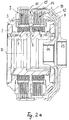
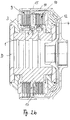
- a hydraulic double clutch according to the Figs. 1 to 5 has a one-piece inner body 1 serving as a coupling hub within the meaning of the invention.
- On the inner body 1 is on the left - on the drawings according to Fig. 2a and 2 B related - a first pressure piston 3 and on the right side a second pressure piston 4 mounted axially displaceable.
- the two pressure pistons 3 and 4 can be hydraulically pressurized in opposite directions to one another.
- a cylinder wall 2 for the first pressure piston 3 is provided on the left and a second cylinder wall for the pressure piston 4 on the right.
- two clutch units in the form of two disk packs 9, 10 are arranged, each of which consists of a plurality of inner and outer disks.
- the inner disks of the two disk packs 9, 10 are held in a rotationally fixed and axially movable manner by longitudinal teeth extending axially to a coupling axis of rotation D.
- the outer disks of the two disk packs 9, 10 are connected in a rotationally fixed and axially movable manner via corresponding external toothing with axially extending internal toothing of two clutch bells 11, 12, the clutch bell 11 assigned to the left disk pack 9 having a first output 13 and the clutch bell 12 assigned to the second disk pack 10 define an output 14 that is coaxially aligned with the first output 13.
- the two plate packs 9, 10 are axially separated from one another by a thrust washer arrangement 15, which is configured in an annular manner and is embedded in an axially centrally arranged radial groove R of the inner body 1.
- the radial groove R is designed to be deeper than the corresponding axial groove depths of the axially extending lamellar toothing of the inner body 1, as can be seen from the Fig. 2a and 2 B is easily recognizable.
- each compression spring arrangement 5, 6 for each pressure piston 3, 4; 7, 8, which comprises a plurality of compression springs 6, 8 distributed over the circumference of the inner body 1.
- the compression springs 6, 8 are designed identically to one another and designed as helical compression springs.
- Each compression spring 6, 8 is in one associated recess 5, 7 integrated in the inner body 1.
- the recesses 5, 7 are made in the form of blind holes from opposite end faces of the inner body 1 and extend axially parallel to the axis of rotation D of the double clutch.
- Each compression spring 6, 8 is consequently supported axially on the inside on a base of the associated recess 5, 7 designed as a blind hole and exerts a compressive force in the release direction on the corresponding pressure piston 3, 4, in which the respective pressure piston 3, 4 axially from the associated disk pack 9, 10 is pushed away.
- the radial groove R and the recesses 5, 7 do not merge into one another, but rather are axially and radially separated from one another, so that the radial groove R is completely closed radially inwards and on both axial sides over its entire circumference.
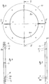
- the pressure disk arrangement 15 has a support ring 17 which is continuous over its entire circumference and which is connected to two semi-annular pressure disk sections 16a, 16b.
- Each semicircular thrust washer section 16a, 16b has an axially protruding, circular arc-shaped shoulder 18, which is provided radially on the inside on the respective thrust washer section 16b.
- An axial extension of the shoulder 18 corresponds approximately to an axial thickness of the carrier ring 17. It must be ensured that the axial thickness of the carrier ring 17 is always slightly greater than the greatest axial extension of the shoulder 18. This ensures that the flat outer surface of the carrier ring is always 17 forms a corresponding friction surface for the adjacent disk pack 10 and an end face of the shoulder 18 does not come into contact with the facing friction surface of the disk pack 10.
- a radial extension from a radial outer side of the shoulder 18 to the radially outer marginal edge of each thrust washer section 16a, 16b is identical to the radial extension of the carrier ring 17, so that the carrier ring 17 is located according to the illustrations according to the Figures 4 and 5 one end face is flat and flush with a facing end face of the respective thrust washer section 16a, 16b and, moreover, with its outer contour flush with the outer surfaces of the respective thrust washer section 16a, 16b both in the area of the shoulders 18 and in the radially outer edge area .
- a feather key P is inserted radially on the inside at the two separating joints of the adjoining thrust washer sections 16a and 16b, to which a corresponding feather key groove N is assigned on the radially inside base of the radial groove R of the inner body 1.
- the two keys P are used when assembling the
- the thrust washer assembly 15 is inserted into the feather key grooves N before the thrust washer sections 16a and 16b are placed radially from the outside onto the inner body 1 and inserted radially into the radial groove R.
- the feather keys P facilitate the positioning of the thrust washer sections 16a, 16b within the radial groove R.
- the carrier ring 17 is pushed axially over the inner body 1 and centered on the arcuate shoulders 18 of the thrust washer sections 16a, 16b.
- the carrier ring 17 is then fixed to the thrust washer sections 16a, 16b by means of axially effective fastening means in the form of screw connections 19.
- the thrust washer sections 16a, 16b have threaded bores, and corresponding receptacles for corresponding head screws are provided in the carrier ring 17, which are screwed into the threaded bores.
- the first disk pack 9 is thus also exposed and can be removed axially from the inner body 1 via the right-hand clutch side.
- a new disk pack 9, the pressure plate assembly 15 and, if necessary, a further new disk pack 10 can then be reinstalled before the pressure piston 4, the associated cylinder wall and the two clutch bells 11 and 12 are axially re-installed and ready for use.
- a radial extension of the carrier ring 17 corresponds approximately to a radial extension of an effective contact surface of the adjacent inner disk of the disk pack 10, the carrier ring 17 radially on the outside also at least largely aligned with an outer edge of the respective Inner lamella closes.
Landscapes
- Engineering & Computer Science (AREA)
- General Engineering & Computer Science (AREA)
- Mechanical Engineering (AREA)
- Hydraulic Clutches, Magnetic Clutches, Fluid Clutches, And Fluid Joints (AREA)
- Mechanical Operated Clutches (AREA)
Description
- Die Erfindung betrifft eine Doppelschaltkupplung mit zwei kraftschlüssig wirksamen Kupplungseinheiten, die auf einer gemeinsamen Kupplungsnabe- auf eine Kupplungsdrehachse bezogen - drehfest und axial beweglich gelagert sind, sowie mit einer axial fest zwischen den Kupplungseinheiten auf der Kupplungsnabe gehaltenen, mehrteiligen Druckscheibenanordnung, und mit zwei axial beweglichen Druckkolben, die mittels jeweils einer in der Kupplungsnabe positionierten Druckfederanordnung lüftbar sind, wobei jede Aussparung in die Kupplungsnabe als axial erstrecktes Sackloch eingebracht ist.
- Eine derartige Doppelschaltkupplung ist aus einem Katalog Nr. D 228 der Firma Stromag AG mit Datum 01.1999 publiziert und als Druckschrift XP-002662055 bekannt. Die bekannte Doppelschaltkupplung weist zwei Lamellenpakete auf, die auf einer gemeinsamen Kupplungsnabe drehfest und axial beweglich gelagert sind. Die beiden Lamellenpakete sind durch eine Druckscheibenanordnung voneinander getrennt, die außen auf der Kupplungsnabe aufsitzt und axial auf der Kupplungsnabe gesichert ist. Die beiden Lamellenpakete sind durch jeweils einen axial beweglichen Druckkolben beaufschlagbar, die mittels jeweils einer in der Kupplungsnabe positionierten Druckfederanordnung in eine Lüftstellung für die Lamellenpakete überführbar sind.
- Aus der
DE 10 2010 046 633 A1 ist eine weitere Doppelschaltkupplung bekannt, bei der eine Druckscheibenanordnung axial zwischen zwei Lamellenpaketen angeordnet ist. Die Druckscheibenanordnung ist in einer nach außen offenen Radialnut der Kupplungsnabe aufgenommen. An der Druckscheibenanordnung stützen sich entsprechende Druckfedern der Druckfederanordnungen zum Lüften der Druckkolben ab. Die entsprechenden Aussparungen gegenüberliegender Druckfedern in der Kupplungsnabe sind koaxial zueinander ausgerichtet und werden jeweils durch eine über die gesamte Länge der Kupplungsnabe durchgängige, gemeinsame Bohrung verwirklicht. Die Druckscheibenanordnung ist dreiteilig aufgebaut aus zwei in Umfangsrichtung aneinanderschließenden Druckscheibenabschnitten sowie einem Trägerring, mit dem die Druckscheibenabschnitte axial verbunden sind. - Andere Doppelschaltkupplungen sind aus der
US 2009/0084652 A1 oder derDE 10 2008 048 801 B3 bekannt. - Aufgabe der Erfindung ist es, eine Doppelschaltkupplung der eingangs genannten Art zu schaffen, die eine Demontage und eine erneute Montage ermöglicht.
- Diese Aufgabe wird dadurch gelöst, dass die Druckscheibenanordnung in einer Radialnut der Kupplungsnabe aufgenommen ist, die - auf die Kupplungsdrehachse bezogen - radial und/oder axial zu den Sacklöchern beabstandet ist. Durch die Aufnahme der Druckscheibenanordnung in der Radialnut wird eine sichere Fixierung der Druckscheibenanordnung auf der Kupplungsnabe erzielt. Dadurch, dass die Radialnut zu den Sacklöchern radial und/oder axial beabstandet ist, kann die Druckscheibenanordnung unbeeinflusst von Lage und Funktion der Druckfederanordnungen montiert und demon-tiert werden. Bei der
DE 10 2010 046 633 A1 war eine Demontage der Druckscheibenanordnung nach erfolgreicher Erstmontage nahezu nicht möglich, da wenigstens eine Druckfederanordnung sich axial an der Druckscheibenanordnung abstützt und aufgrund der hohen Federspannung eine Demontage der Druckscheibenanordnung nicht oder nur unter erschwerten Bedingungen möglich macht. - In Ausgestaltung der Erfindung weist die Druckscheibenanordnung wenigstens zwei in Umfangsrichtung aneinanderschließende Druckscheibenabschnitte sowie einen einteiligen Trägerring auf, mit dem die Druckscheibenabschnitte verbunden sind. In vorteilhafter Weise weist jeder Druckscheibenabschnitt radial innenliegend einen axial erstreckten Absatz auf, an den der Trägerring radial nach außen ansetzt. Dabei entspricht vorzugsweise eine Axialerstreckung des Absatzes einer axialen Dicke des Trägerringes. Um eine ausschließliche Reibanlage des Trägerringes zu gewährleisten, ist der Trägerring vorzugsweise immer geringfügig dicker als die Axialerstreckung des Absatzes. In vorteilhafter Weise entspricht ein radialer Abstand des Absatzes zu einer radial äußeren Randkante des jeweiligen Druckscheibenabschnittes einer Radialerstreckung des Trägerringes. Durch die beschriebenen Ausgestaltungen wird für die Kupplungseinheiten eine Anlagefläche an einem planen Teil der Druckscheibenanordnung erzielt, wodurch sich eine besonders gleichmäßige Flächenpressung für die entsprechenden Kupplungseinheiten ergibt. In weiterer Ausgestaltung entspricht die Radalerstreckung des Trägerringes zumindest weitgehend einer Radialerstreckung einer wirksamen Anlagefläche der benachbarten Kupplungseinheit. Als Kupplungseinheit ist bevorzugt ein Lamellenpaket aus mehreren Innen- und Außenlamellen vorgesehen. Sowohl der Trägerring gegenüber der benachbarten Kupplungseinheit wie auch eine der anderen Kupplungseinheit zugewandte Stirnfläche der wenigstens zwei Druckscheibenabschnitte bilden entsprechend plane und radial einteilig durchgängige Anlageflächen. Durch die Ausgestaltungen liegt der Trägerring zudem radial nach innen abgestützt passgenau an den Druckscheibenabschnitten an, so dass Außenflächen des Trägerringes bündig und fluchtend mit korrespondierenden Außenkonturen der Druckscheibenabschnitte abschließen. Hierdurch liegen die Druckscheibenabschnitte und der Trägerring besonders kompakt und paketförmig aneinander an, so dass sich im Kupplungsbetrieb allenfalls geringe elastische Verformungen zwischen Trägerring und Druckscheibenabschnitten ergeben. Auch durch diese Maßnahmen ergibt sich eine besonders gleichmäßige Flächenpressung der Druckscheibenanordnung relativ zu den benachbarten Kupplungseinheiten, insbesondere Lamellenpaketen. Durch die beschriebenen Ausgestaltungen liegen die Druckscheibenabschnitte und der Trägerring derart flächig aneinander an, dass im Kupplungsbetrieb auch bei elastischen Verformungen ein Kraftfluss immer über die breiten Anlageflächen zwischen den Druckscheibenabschnitten und dem Trägerring erfolgt.
- In weiterer Ausgestaltung der Erfindung sind die wenigstens zwei Druckscheibenabschnitte an ihren in Umfangsrichtung gesehenen Trennfugen jeweils durch eine Passfeder zueinander beabstandet gehalten, die in jeweils eine komplementäre Passfedernut an einem Grund der Radialnut eingepasst ist. Dies ermöglicht eine verbesserte Montierbarkeit der Druckscheibenanordnung auf der Kupplungsnabe.
- Durch die erfindungsgemäße Lösung ist es möglich, eine Demontage der Doppelschaltkupplung von einer Axialseite her zu ermöglichen und demzufolge die entsprechenden Kupplungseinheiten, insbesondere Lamellenpakete, auszutauschen. Die erfindungsgemäße Doppelschaltkupplung ist vorteilhaft für den Einsatz bei einem Industriegetriebe vorgesehen, vorzugsweise für einen Antrieb einer Explorationspumpe für die Förderung von Erdöl. Alternativ kann die Erfindung auch bei Werkzeugmaschinen, bei Industrieanlagen oder bei Nutzfahrzeugen eingesetzt werden.
- Weitere Vorteile und Merkmale der Erfindung ergeben sich aus den Ansprüchen sowie aus der nachfolgenden Beschreibung eines bevorzugten Ausführungsbeispiels der Erfindung, das anhand der Zeichnungen dargestellt ist.
-
Fig. 1 zeigt in einer Frontansicht eine Ausführungsform einer erfindungsgemäßen Dcppelschaltkupplung, -
Fig. 2a einen Längsschnitt durch die Doppelschaltkupplung entlang der Schnittlinie a-a inFig. 1 , -
Fig. 2b einen Längsschnitt durch die Doppelschaltkupplung nachFig. 1 entlang der Schnittlinie b-b, -
Fig. 3 in vergrößerter Frontansicht eine mehrteilige Druckscheibenanordnung der Doppelschaltkupplung nach denFig. 1 bis 2b , -
Fig. 4 eine Schnittdarstellung der Druckscheibenanordnung entlang der Schnittlinie IV-IV inFig. 3 und -
Fig. 5 eine weitere Schnittdarstellung der Druckscheibenanordnung nachFig. 3 entlang der Schnittlinie V-V inFig. 3 - Eine hydraulische Doppelschaltkupplung nach den
Fig. 1 bis 5 weist einen als Kupplungsnabe im Sinne der Erfindung dienenden, einteiligen Innenkörper 1 auf. Auf dem Innenkörper 1 ist linksseitig - auf die Zeichnungen gemäß denFig. 2a und2b bezogen - ein erster Druckkolben 3 und rechtsseitig ein zweiter Druckkolben 4 axial verschiebbar gelagert. Die beiden Druckkolben 3 und 4 sind gegenläufig zueinander hydraulisch druckbeaufschlagbar. Hierzu ist linksseitig eine Zylinderwand 2 für den ersten Drucckolben 3 und rechtsseitig eine zweite Zylinderwand für den Druckkolben 4 vorgesehen. Zwischen den axial zueinander beabstandeten Druckkolben 3 sind zwei Kupplungseinheiten in Form von zwei Lamellenpaketen 9, 10 angeordnet, die jeweils aus mehreren Innen- und Außenlamellen bestehen. Die Innenlamellen der beiden Lamellenpakete 9, 10 sind drehfest und axial beweglich über axial zu einer Kupplungsdrehachse D erstreckte Längsverzahnungen gehalten. Die Außenlamellen der beiden Lamellenpakete 9, 10 sind über entsprechende Außenverzahnungen mit axial erstreckten Innenverzahnungen von zwei Kupplungsglocken 11, 12 drehfest und axial beweglich verbunden, wobei die dem linken Lamellenpaket 9 zugeordnete Kupplungsglocke 11 einen ersten Abtrieb 13 und die dem zweiten Lamellenpaket 10 zugeordnete Kupplungsglocke 12 einen Abtrieb 14 definieren, der zum ersten Abtrieb 13 koaxial ausgerichtet ist. - Die beiden Lamellenpakete 9, 10 sind durch eine Druckscheibenanordnung 15 axial voneinander getrennt, die ringförmig gestaltet ist und in einer axial mittig angeordneten Radialnut R des Innenkörpers 1 eingebettet ist. Die Radialnut R ist tiefer gestaltet als entsprechende Axialnuttiefen der axial erstreckten Lamellenverzahnung des Innenkörpers 1, wie aus den
Fig. 2a und2b gut erkennbar ist. - In dem Innenkörper 1 ist zudem für jeden Druckkolben 3, 4 jeweils eine Druckfederarordnung 5, 6; 7, 8 integriert, die mehrere, über den Umfang des Innenkörpers 1 verteilt angeordnete Druckfedern 6, 8 umfasst. Die Druckfedern 6, 8 sind identisch zueinander gestaltet und als Schraubendruckfedern ausgeführt. Jede Druckfeder 6, 8 ist in einer zugehörigen Aussparung 5, 7 im Innenkörper 1 integriert. Die Aussparungen 5, 7 sind als Sacklöcher von gegenüberliegenden Stirnseiten des Innenkörpers 1 her in diesen eingebracht und erstrecken sich achsparallel zur Drehachse D der Doppelschaltkupplung. Jede Druckfeder 6, 8 stützt sich demzufolge axial innenseitig an einem Grund der zugeordneten, als Sackloch gestalteten Aussparung 5, 7 ab und übt auf den entsprechenden Druckkolben 3, 4 eine Druckkraft in Lüftrichtung aus, in der der jeweilige Druckkolben 3, 4 axial von dem zugehörigen Lamellenpaket 9, 10 weggedrückt wird. Die Radialnut R und die Aussparungen 5, 7 gehen nicht ineinander über, sondern sind vielmehr axial und radial voneinander getrennt, so dass die Radialnut R radial nach innen sowie zu beiden Axialseiten hin über ihren gesamten Umfang vollständig geschlossen ist.
- Die Druckscheibenanordnung 15 weist einen über seinen gesamten Umfang durchgängig einteiligen Trägerring 17 auf, der mit zwei halbringförmigen Druckscheibenabschnitten 16a, 16b verbunden ist. Jeder halbkreisförmige Druckscheibenabschnitt 16a, 16b weist einen axial abragenden, kreisbogenförmigen Absatz 18 auf, der radial innenseitig an dem jeweiligen Druckscheibenabschnitt 16b vorgesehen ist. Eine Axialerstreckung des Absatzes 18 entspricht in etwa einer axialen Dicke des Trägerringes 17. Dabei muss sichergestellt sein, dass die axiale Dicke des Trägerringes 17 immer geringfügig größer ist als die größte Axialerstreckung des Absatzes 18. Dadurch ist gewährleistet, dass immer die plane Außenfläche des Trägerringes 17 eine entsprechende Reibfläche für das benachbarte Lamellenpaket 10 bildet und eine Stirnfläche des Absatzes 18 nicht mit der zugewandten Reibfläche des Lamellenpakets 10 in Berührung gelangt. Eine Radialerstreckung von einer radialen Außenseite des Absatzes 18 ausgehend bis zur radial äußeren Randkante jedes Druckscheibenabschnittes 16a, 16b ist identisch zur radialen Erstreckung des Trägerringes 17, so dass der Trägerring 17 sich gemäß den Darstellungen nach den
Fig. 4 und 5 mit seiner einen Stirnfläche flächig und bündig an eine zugewandte Stirnfläche des jeweiligen Druckscheibenabschnittes 16a, 16b anschmiegt und im Übrigen mit seiner Außenkontur bündig und fluchtend mit den Außenflächen des jeweiligen Druckscheibenabschnittes 16a, 16b sowohl im Bereich der Absätze 18 als auch im radial außen liegenden Randbereich abschließt. - An den beiden Trennfugen der aneinandergrenzenden Druckscheibenabschnitte 16a und 16b ist radial innenseitig jeweils eine Passfeder P eingefügt, der am radial innenseitigen Grund der Radialnut R des Innenkörpers 1 jeweils eine korrespondierende Passfedernut N zugeordnet ist. Die beiden Passfedern P werden bei einer Montage der Druckscheibenanordnung 15 in die Passfedernuten N eingesetzt, bevor die Druckscheibenabschnitte 16a und 16b radial von außen her auf den Innenkörper 1 aufgesetzt und in die Radialnut R radial eingesetzt werden. Die Passfedern P erleichtern die Positionierung der Druckscheibenabschnitte 16a, 16b innerhalb der Radialnut R. Nach dem Einsetzen der Druckscheibenabschnitte 16a, 16b wird der Trägerring 17 axial über den Innenkörper 1 geschoben und auf den kreisbogenförmigen Absätzen 18 der Druckscheibenabschnitte 16a, 16b zentriert. Anschließend wird der Trägerring 17 mittels axial wirksamer Befestigungsmittel in Form von Schraubverbindungen 19 an den Druckscheibenabschnitten 16a, 16b fixiert. Hierzu weisen die Druckscheibenabschnitte 16a, 16b Gewindebohrungen auf und im Trägerring 17 sind korrespondierende Aufnahmen für entsprechende Kopfschrauben vorgesehen, die in die Gewindebohrungen eingeschraubt werden.
- Bei der anhand der
Fig. 1 bis 5 dargestellten Doppelschaltkupplung ist ein einfacher Austausch der Lamellenpakete 9, 10 von einer Kupplungsseite her möglich. Dies ist die in der Darstellung nach denFig. 2a und2b rechte Kupplungsseite. Nach dem axialen Abziehen der beiden Kupplungsglocken 11 und 12 wird die dem Druckkolben 4 zugeordnete Zylinderwand demontiert. Nach dem axialen Abziehen des Druckkolbens 4 wird das Lamellenpaket 10 axial entfernt. Anschließend wird der Trägerring 17 der Druckscheibenanordnung 15 von dem verbleibenden Druckscheibenabschnitt abgeschraubt und axial nach rechts entfernt. Anschließend können die Druckscheibenabschnitte 16a, 16b radial nach außen aus der Radialnut R des Innenkörpers 1 herausgezogen werden. Damit liegt auch das erste Lamellenpaket 9 frei und kann axial über die rechte Kupplungsseite vom Innenkörper 1 entfernt werden. Durch entsprechend umgekehrte Montagevorgänge können anschließend ein neues Lamellenpaket 9, die Druckscheibenanordnung 15 und gegebenenfalls ein weiteres neues Lamellenpaket 10 wieder montiert werden, bevor auch der Druckkolben 4, die zugehörige Zylinderwand sowie die beiden Kupplungsglocken 11 und 12 wieder axial aufgesetzt und betriebsfertig montiert werden. - Die in Umfangsrichtung drehfeste Positionierung der Passfedern P innerhalb der Radialnut R gewährleistet eine drehfeste Abstützung für die Druckscheibenabschnitte 16a, 16b und demzufolge eine sichere drehfeste Mitnahme gemeinsam mit dem Innenkörper 1. Wie anhand der
Fig. 2a und2b gut erkennbar ist, entspricht eine Radialerstreckung des Trägerringes 17 etwa einer Radialerstreckung einer wirksamen Anlagefläche der benachbarten Innenlamelle des Lamellenpaketes 10, wobei der Trägerring 17 radial außenseitig auch zumindest weitgehend fluchtend mit einem Außenrand der ertsprechenden Innenlamelle abschließt. Dadurch ergibt sich zwischen der zugewandten Stirnfläche des Trägerringes 17 und der dem Trägerring 17 zugewandten Anlagefläche der benachbarten Innenlamelle des Lamellenpaketes 10 eine durchgängig plane Anlagefläche, wodurch eine besonders gute Flächenpressung erzielbar ist. Da auch die gegenüberliegenden Stirnflächen der Druckscheibenabschnitte 16a, 16b, die dem anderen Lamellenpaket 9 zugewandt sind, über ihre gesamte Radialerstreckung eine durchgängig plane Fläche bilden, ergibt sich auf der dem anderen Lamellenpaket 9 zugewandten Stirnseite eine besonders gleichmäßige Flächenpressung.
Claims (8)
- Doppelschaltkupplung mit zwei kraftschlüssig wirksamen Kupplungseinheiten (9, 10) die auf einer gemeinsamen, einteiligen Kupplungsnabe - (1) - auf eine Kupplungsdrehachse (D) bezogen - drehfest und axial beweglich gelagert sind, sowie mit einer axial fest zwischen den Kupplungseinheiten auf der Kupplungsnabe gehaltenen, mehrteiligen Druckscheibenanordnung (15), und mit zwei axial beweglichen Druckkolben (3, 4) die mittels jeweils einer in der Kupplungsnabe positionierten Druckfederanordnung lüftbar sind, wobei jede Druckfederanordnung mehrere Druckfedern (6, 8) umfasst, die in jeweils einer Aussparung (5, 7) der Kupplungsnabe angeordnet sind, wobei jede Aussparung in die Kupplungsnabe als axial erstrecktes Sackloch eingebracht ist, dadurch gekennzeichnet, dass die Druckscheibenanordnung (15) in einer Radialnut (R) der Kupplungsnabe (1) aufgenommen ist, die - auf die Kupplungsdrehachse (D) bezogen - radial und/oder axial zu den Sacklöchern (5, 7) beabstandet ist.
- Doppelschaltkupplung nach Anspruch 1, dadurch gekennzeichnet, dass die Druckscheibenanordnung (15) wenigstens zwei in Umfangsrichtung aneinanderschließende Druckscheibenabschnitte (16a, 16b) sowie einen einteiligen Trägerring (17) aufweist, mit dem die Druckscheibenabschnitte (16a, 16b) verbunden sind.
- Doppelschaltkupplung nach Anspruch 2, dadurch gekennzeichnet, dass jeder Druckscheibenabschnitt (16a, 16b) radial innenliegend einen axial erstreckten Absatz (18) aufweist, an den der Trägerring (17) radial nach außen ansetzt.
- Doppelschaltkupplung nach Anspruch 3, dadurch gekennzeichnet, dass eine Axialerstreckung des Absatzes (18) einer axialen Dicke des Trägerringes (17) entspricht.
- Doppelschaltkupplung nach Anspruch 3 oder 4, dadurch gekennzeichnet, dass ein radialer Abstand des Absatzes (18) zu einer radial äußeren Randkante des jeweiligen Druckscheibenabschnittes (16a, 16b) einer Radialerstreckung des Trägerringes (17) entspricht.
- Doppelschaltkupplung nach einem der vorhergehenden Ansprüche, dadurch gekennzeichnet, dass die Radialerstreckung des Trägerringes (17) zumindest weitgehend einer Radialerstreckung einer wirksamen Anlagefläche der benachbarten Kupplungseinheit (9, 10) entspricht.
- Doppelschaltkupplung nach einem der vorhergehenden Ansprüche, dadurch gekennzeichnet, dass axial wirksame Befestigungsmittel (19) vorgesehen sind, die die Druckscheibenabschnitte (16a, 16b) mit dem Trägerring (17) verbinden.
- Doppelschaltkupplung nach einem der vorhergehenden Ansprüche, dadurch gekennzeichnet, dass die wenigstens zwei Druckscheibenabschnitte (16a, 16b) an ihren in Umfangsrichtung gesehenen Trennfugen jeweils durch eine Passfeder (P) zueinander beabstandet gehalten sind, die in jeweils eine komplementäre Passfedernut (N) an einem Grund der Radialnut (R) eingepasst ist.
Applications Claiming Priority (2)
| Application Number | Priority Date | Filing Date | Title |
|---|---|---|---|
| DE102012222915.9A DE102012222915B4 (de) | 2012-12-12 | 2012-12-12 | Doppelschaltkupplung mit zwei kraftschlüssig wirksamen Kupplungseinheiten |
| PCT/EP2013/076116 WO2014090817A1 (de) | 2012-12-12 | 2013-12-10 | Doppelschaltkupplung mit zwei kraftschlüssig wirksamen kupplungseinheiten |
Publications (2)
| Publication Number | Publication Date |
|---|---|
| EP2932128A1 EP2932128A1 (de) | 2015-10-21 |
| EP2932128B1 true EP2932128B1 (de) | 2020-11-18 |
Family
ID=49766071
Family Applications (1)
| Application Number | Title | Priority Date | Filing Date |
|---|---|---|---|
| EP13805841.7A Active EP2932128B1 (de) | 2012-12-12 | 2013-12-10 | Doppelschaltkupplung mit zwei kraftschlüssig wirksamen kupplungseinheiten |
Country Status (6)
| Country | Link |
|---|---|
| US (1) | US9752625B2 (de) |
| EP (1) | EP2932128B1 (de) |
| CN (1) | CN104995423B (de) |
| CA (1) | CA2892964C (de) |
| DE (1) | DE102012222915B4 (de) |
| WO (1) | WO2014090817A1 (de) |
Families Citing this family (5)
| Publication number | Priority date | Publication date | Assignee | Title |
|---|---|---|---|---|
| CN110582653B (zh) | 2017-05-09 | 2021-02-26 | Gkn汽车有限公司 | 双离合器单元和带有这样的双离合器单元的电驱动器 |
| JP6713499B2 (ja) | 2018-03-13 | 2020-06-24 | 本田技研工業株式会社 | 摩擦係合装置 |
| CN109058320A (zh) * | 2018-08-01 | 2018-12-21 | 格特拉克(江西)传动系统有限公司 | 一种湿式双离合器冷却油孔活塞回复结构 |
| JP7367412B2 (ja) * | 2019-09-10 | 2023-10-24 | 株式会社ジェイテクト | 駆動力配分装置 |
| CN114211950A (zh) * | 2021-12-24 | 2022-03-22 | 奇瑞汽车股份有限公司 | 混合动力系统及车辆 |
Family Cites Families (26)
| Publication number | Priority date | Publication date | Assignee | Title |
|---|---|---|---|---|
| DE10596C (de) | c. J. galloway und J. H. beckwith in Manchester (England) | Reibungskuppelungen mit hydraulischem Gestänge innerhalb der Welle | ||
| US2953034A (en) | 1959-09-21 | 1960-09-20 | Weaver William Arthur | Reduction gearing and clutch combination |
| US3032157A (en) * | 1959-12-18 | 1962-05-01 | Borg Warner | Double acting clutch |
| US3157057A (en) | 1961-08-04 | 1964-11-17 | Gen Motors Corp | Plate type friction coupling |
| US3472350A (en) * | 1968-01-19 | 1969-10-14 | Twin Disc Inc | Hydraulically operated friction clutch of the dual actuating chamber type having a sequencing valve |
| DE2431104B2 (de) | 1974-06-28 | 1976-04-29 | Mtu Friedrichshafen Gmbh | Lamellenkupplung |
| DE2618356C2 (de) * | 1976-04-27 | 1983-11-03 | Zahnradfabrik Friedrichshafen Ag, 7990 Friedrichshafen | Drucköl- und Schmierölzuführung |
| EP0188415B1 (de) * | 1983-09-15 | 1987-12-02 | ZF FRIEDRICHSHAFEN Aktiengesellschaft | Antriebseinrichtung |
| DE3425346C2 (de) | 1984-07-10 | 1986-12-18 | Maschinenfabrik Stromag Gmbh, 4750 Unna | Reibungskupplung- oder bremse |
| US4947974A (en) | 1988-01-15 | 1990-08-14 | Deere & Company | Fast fill hydraulic clutch |
| US5031739A (en) | 1989-05-11 | 1991-07-16 | Dana Corporation | Two piece clutch brake |
| DE19840326C1 (de) | 1998-09-04 | 2000-04-06 | Gkn Viscodrive Gmbh | Verfahren und eine Vorrichtung zur Drehmomentverteilung von einer Längsantriebswelle auf zwei Achswellen |
| DE50001452D1 (de) * | 2000-10-05 | 2003-04-17 | Ford Global Tech Inc | Doppelkupplung für ein Getriebe mit zwei Getriebeeingangswellen |
| EP1522753B1 (de) | 2003-10-11 | 2006-02-08 | BorgWarner Inc. | Hydraulische Doppelkupplung |
| DE502004004086D1 (de) | 2004-06-17 | 2007-07-26 | Borgwarner Inc | Rückenplatte für eine Doppelkupplung in axial paralleler Bauart |
| ATE391858T1 (de) | 2004-08-26 | 2008-04-15 | Hoerbiger & Co | Hydraulische doppelkupplung |
| ATE415572T1 (de) * | 2004-09-03 | 2008-12-15 | Luk Lamellen & Kupplungsbau | Drehmomentübertragungseinrichtung |
| ATE438044T1 (de) | 2005-01-27 | 2009-08-15 | Getrag Ford Transmissions Gmbh | Doppelkupplung mit gleichgrossen lamellen |
| US8479905B2 (en) * | 2007-03-30 | 2013-07-09 | Eaton Corporation | Dual clutch arrangement with two piece main rotating manifold |
| US8967352B2 (en) * | 2007-03-30 | 2015-03-03 | Eaton Corporation | Low driven inertia dual clutch |
| DE102008048801B3 (de) * | 2008-09-24 | 2010-06-17 | Getrag Ford Transmissions Gmbh | Abstützelement für eine Kupplungsvorrichtung mit zwei Reibkupplungen |
| JP4805324B2 (ja) | 2008-10-29 | 2011-11-02 | 株式会社エフ・シー・シー | 多板式クラッチ装置 |
| WO2011089825A1 (ja) * | 2010-01-25 | 2011-07-28 | 本田技研工業株式会社 | 動力伝達装置 |
| DE102010046633B4 (de) * | 2010-09-20 | 2012-10-18 | Gkn Stromag Ag | Doppelschaltkupplung |
| CN201884506U (zh) * | 2010-12-02 | 2011-06-29 | 中国一拖集团有限公司 | 拖拉机负载换向离合器装置 |
| CN102562850A (zh) * | 2010-12-20 | 2012-07-11 | 陕西航天动力高科技股份有限公司 | 一种湿式离合器 |
-
2012
- 2012-12-12 DE DE102012222915.9A patent/DE102012222915B4/de not_active Expired - Fee Related
-
2013
- 2013-12-10 CN CN201380065279.5A patent/CN104995423B/zh active Active
- 2013-12-10 CA CA2892964A patent/CA2892964C/en active Active
- 2013-12-10 EP EP13805841.7A patent/EP2932128B1/de active Active
- 2013-12-10 US US14/651,481 patent/US9752625B2/en active Active
- 2013-12-10 WO PCT/EP2013/076116 patent/WO2014090817A1/de not_active Ceased
Non-Patent Citations (1)
| Title |
|---|
| None * |
Also Published As
| Publication number | Publication date |
|---|---|
| EP2932128A1 (de) | 2015-10-21 |
| WO2014090817A1 (de) | 2014-06-19 |
| US20150330461A1 (en) | 2015-11-19 |
| US9752625B2 (en) | 2017-09-05 |
| CA2892964C (en) | 2020-03-24 |
| CA2892964A1 (en) | 2014-06-19 |
| DE102012222915A1 (de) | 2014-06-12 |
| CN104995423A (zh) | 2015-10-21 |
| CN104995423B (zh) | 2017-05-17 |
| DE102012222915B4 (de) | 2014-12-31 |
Similar Documents
| Publication | Publication Date | Title |
|---|---|---|
| DE102011120393B4 (de) | Zentrifugal ausgeglichene Hydraulikkupplungsanordnung | |
| DE102015213874A1 (de) | Axiale Lamellenkupplung | |
| DE102012222915B4 (de) | Doppelschaltkupplung mit zwei kraftschlüssig wirksamen Kupplungseinheiten | |
| DE102012218829B4 (de) | Doppelkupplung und Verfahren zu deren Montage | |
| EP3177843B1 (de) | Axiale lamellenkupplung | |
| DE102015205832A1 (de) | Axiale Lamellenkupplung | |
| DE102006004760A1 (de) | Hydraulischer Nockenwellenversteller | |
| DE10227328A1 (de) | Reibungskupplung | |
| EP3572669B1 (de) | Anschlussbaugruppe mit speisepumpe und elastischem element | |
| WO2020169140A1 (de) | Kompakte kupplungsanordnung mit lamellenträgersystem | |
| EP1726842A1 (de) | Kupplungsanordnung in radial geschachtelter Bauart | |
| DE112011103001B4 (de) | Getriebekolben mit eingeschlossener Rückstellfeder | |
| EP2619473B1 (de) | Doppelschaltkupplung | |
| DE102015213873A1 (de) | Axiale Lamellenkupplung | |
| EP3927991B1 (de) | Kompakte kupplungsanordnung mit einem stützkörper | |
| DE102009023128B4 (de) | Verfahren zum Herstellen eines Außenkörpers einer Lamellenbremse | |
| WO2011157541A1 (de) | Reibscheibe und nockenwellenverstellsystem | |
| DE102014204865B4 (de) | Rotationsbauteil, Verzahnung zweier Rotationsbauteile sowie Verfahren zum Herstellen eines Rotationsbauteils | |
| DE102021107695B4 (de) | Drehmomentübertragungsvorrichtung für einen Antriebsstrang eines Kraftfahrzeugs | |
| DE102014212267A1 (de) | Wälzlagerkäfig | |
| EP2999906B1 (de) | Gleitringdichtung mit verbesserter drehmomentübertragung | |
| EP2179192B1 (de) | Reibungskupplung, insbesondere für den antriebsstrang eines fahrzeugs | |
| DE102015200891B3 (de) | Druckplatte zum Verpressen einer Kupplungsscheibe für eine Reibungskupplung, Baukastensystem zur Herstellung einer Druckplatte sowie Verfahren zur Herstellung einer Druckplatte | |
| EP3743640B1 (de) | Tilgersystem | |
| AT520114B1 (de) | Reiblamelle |
Legal Events
| Date | Code | Title | Description |
|---|---|---|---|
| PUAI | Public reference made under article 153(3) epc to a published international application that has entered the european phase |
Free format text: ORIGINAL CODE: 0009012 |
|
| 17P | Request for examination filed |
Effective date: 20150617 |
|
| AK | Designated contracting states |
Kind code of ref document: A1 Designated state(s): AL AT BE BG CH CY CZ DE DK EE ES FI FR GB GR HR HU IE IS IT LI LT LU LV MC MK MT NL NO PL PT RO RS SE SI SK SM TR |
|
| AX | Request for extension of the european patent |
Extension state: BA ME |
|
| DAX | Request for extension of the european patent (deleted) | ||
| 17Q | First examination report despatched |
Effective date: 20160729 |
|
| STAA | Information on the status of an ep patent application or granted ep patent |
Free format text: STATUS: EXAMINATION IS IN PROGRESS |
|
| RAP1 | Party data changed (applicant data changed or rights of an application transferred) |
Owner name: STROMAG GMBH |
|
| GRAP | Despatch of communication of intention to grant a patent |
Free format text: ORIGINAL CODE: EPIDOSNIGR1 |
|
| STAA | Information on the status of an ep patent application or granted ep patent |
Free format text: STATUS: GRANT OF PATENT IS INTENDED |
|
| INTG | Intention to grant announced |
Effective date: 20200630 |
|
| GRAS | Grant fee paid |
Free format text: ORIGINAL CODE: EPIDOSNIGR3 |
|
| GRAA | (expected) grant |
Free format text: ORIGINAL CODE: 0009210 |
|
| STAA | Information on the status of an ep patent application or granted ep patent |
Free format text: STATUS: THE PATENT HAS BEEN GRANTED |
|
| AK | Designated contracting states |
Kind code of ref document: B1 Designated state(s): AL AT BE BG CH CY CZ DE DK EE ES FI FR GB GR HR HU IE IS IT LI LT LU LV MC MK MT NL NO PL PT RO RS SE SI SK SM TR |
|
| REG | Reference to a national code |
Ref country code: GB Ref legal event code: FG4D Free format text: NOT ENGLISH |
|
| REG | Reference to a national code |
Ref country code: CH Ref legal event code: EP |
|
| REG | Reference to a national code |
Ref country code: IE Ref legal event code: FG4D Free format text: LANGUAGE OF EP DOCUMENT: GERMAN |
|
| REG | Reference to a national code |
Ref country code: DE Ref legal event code: R096 Ref document number: 502013015314 Country of ref document: DE |
|
| REG | Reference to a national code |
Ref country code: AT Ref legal event code: REF Ref document number: 1336106 Country of ref document: AT Kind code of ref document: T Effective date: 20201215 |
|
| REG | Reference to a national code |
Ref country code: NL Ref legal event code: MP Effective date: 20201118 |
|
| PG25 | Lapsed in a contracting state [announced via postgrant information from national office to epo] |
Ref country code: PT Free format text: LAPSE BECAUSE OF FAILURE TO SUBMIT A TRANSLATION OF THE DESCRIPTION OR TO PAY THE FEE WITHIN THE PRESCRIBED TIME-LIMIT Effective date: 20210318 Ref country code: NO Free format text: LAPSE BECAUSE OF FAILURE TO SUBMIT A TRANSLATION OF THE DESCRIPTION OR TO PAY THE FEE WITHIN THE PRESCRIBED TIME-LIMIT Effective date: 20210218 Ref country code: FI Free format text: LAPSE BECAUSE OF FAILURE TO SUBMIT A TRANSLATION OF THE DESCRIPTION OR TO PAY THE FEE WITHIN THE PRESCRIBED TIME-LIMIT Effective date: 20201118 Ref country code: RS Free format text: LAPSE BECAUSE OF FAILURE TO SUBMIT A TRANSLATION OF THE DESCRIPTION OR TO PAY THE FEE WITHIN THE PRESCRIBED TIME-LIMIT Effective date: 20201118 Ref country code: GR Free format text: LAPSE BECAUSE OF FAILURE TO SUBMIT A TRANSLATION OF THE DESCRIPTION OR TO PAY THE FEE WITHIN THE PRESCRIBED TIME-LIMIT Effective date: 20210219 |
|
| PG25 | Lapsed in a contracting state [announced via postgrant information from national office to epo] |
Ref country code: SE Free format text: LAPSE BECAUSE OF FAILURE TO SUBMIT A TRANSLATION OF THE DESCRIPTION OR TO PAY THE FEE WITHIN THE PRESCRIBED TIME-LIMIT Effective date: 20201118 Ref country code: IS Free format text: LAPSE BECAUSE OF FAILURE TO SUBMIT A TRANSLATION OF THE DESCRIPTION OR TO PAY THE FEE WITHIN THE PRESCRIBED TIME-LIMIT Effective date: 20210318 Ref country code: PL Free format text: LAPSE BECAUSE OF FAILURE TO SUBMIT A TRANSLATION OF THE DESCRIPTION OR TO PAY THE FEE WITHIN THE PRESCRIBED TIME-LIMIT Effective date: 20201118 Ref country code: LV Free format text: LAPSE BECAUSE OF FAILURE TO SUBMIT A TRANSLATION OF THE DESCRIPTION OR TO PAY THE FEE WITHIN THE PRESCRIBED TIME-LIMIT Effective date: 20201118 Ref country code: BG Free format text: LAPSE BECAUSE OF FAILURE TO SUBMIT A TRANSLATION OF THE DESCRIPTION OR TO PAY THE FEE WITHIN THE PRESCRIBED TIME-LIMIT Effective date: 20210218 |
|
| REG | Reference to a national code |
Ref country code: LT Ref legal event code: MG9D |
|
| PG25 | Lapsed in a contracting state [announced via postgrant information from national office to epo] |
Ref country code: HR Free format text: LAPSE BECAUSE OF FAILURE TO SUBMIT A TRANSLATION OF THE DESCRIPTION OR TO PAY THE FEE WITHIN THE PRESCRIBED TIME-LIMIT Effective date: 20201118 |
|
| PG25 | Lapsed in a contracting state [announced via postgrant information from national office to epo] |
Ref country code: LT Free format text: LAPSE BECAUSE OF FAILURE TO SUBMIT A TRANSLATION OF THE DESCRIPTION OR TO PAY THE FEE WITHIN THE PRESCRIBED TIME-LIMIT Effective date: 20201118 Ref country code: RO Free format text: LAPSE BECAUSE OF FAILURE TO SUBMIT A TRANSLATION OF THE DESCRIPTION OR TO PAY THE FEE WITHIN THE PRESCRIBED TIME-LIMIT Effective date: 20201118 Ref country code: SK Free format text: LAPSE BECAUSE OF FAILURE TO SUBMIT A TRANSLATION OF THE DESCRIPTION OR TO PAY THE FEE WITHIN THE PRESCRIBED TIME-LIMIT Effective date: 20201118 Ref country code: SM Free format text: LAPSE BECAUSE OF FAILURE TO SUBMIT A TRANSLATION OF THE DESCRIPTION OR TO PAY THE FEE WITHIN THE PRESCRIBED TIME-LIMIT Effective date: 20201118 Ref country code: CZ Free format text: LAPSE BECAUSE OF FAILURE TO SUBMIT A TRANSLATION OF THE DESCRIPTION OR TO PAY THE FEE WITHIN THE PRESCRIBED TIME-LIMIT Effective date: 20201118 Ref country code: EE Free format text: LAPSE BECAUSE OF FAILURE TO SUBMIT A TRANSLATION OF THE DESCRIPTION OR TO PAY THE FEE WITHIN THE PRESCRIBED TIME-LIMIT Effective date: 20201118 |
|
| REG | Reference to a national code |
Ref country code: CH Ref legal event code: PL |
|
| REG | Reference to a national code |
Ref country code: DE Ref legal event code: R097 Ref document number: 502013015314 Country of ref document: DE |
|
| PG25 | Lapsed in a contracting state [announced via postgrant information from national office to epo] |
Ref country code: DK Free format text: LAPSE BECAUSE OF FAILURE TO SUBMIT A TRANSLATION OF THE DESCRIPTION OR TO PAY THE FEE WITHIN THE PRESCRIBED TIME-LIMIT Effective date: 20201118 Ref country code: MC Free format text: LAPSE BECAUSE OF FAILURE TO SUBMIT A TRANSLATION OF THE DESCRIPTION OR TO PAY THE FEE WITHIN THE PRESCRIBED TIME-LIMIT Effective date: 20201118 |
|
| REG | Reference to a national code |
Ref country code: BE Ref legal event code: MM Effective date: 20201231 |
|
| PLBE | No opposition filed within time limit |
Free format text: ORIGINAL CODE: 0009261 |
|
| STAA | Information on the status of an ep patent application or granted ep patent |
Free format text: STATUS: NO OPPOSITION FILED WITHIN TIME LIMIT |
|
| 26N | No opposition filed |
Effective date: 20210819 |
|
| PG25 | Lapsed in a contracting state [announced via postgrant information from national office to epo] |
Ref country code: IE Free format text: LAPSE BECAUSE OF NON-PAYMENT OF DUE FEES Effective date: 20201210 Ref country code: AL Free format text: LAPSE BECAUSE OF FAILURE TO SUBMIT A TRANSLATION OF THE DESCRIPTION OR TO PAY THE FEE WITHIN THE PRESCRIBED TIME-LIMIT Effective date: 20201118 Ref country code: LU Free format text: LAPSE BECAUSE OF NON-PAYMENT OF DUE FEES Effective date: 20201210 Ref country code: NL Free format text: LAPSE BECAUSE OF FAILURE TO SUBMIT A TRANSLATION OF THE DESCRIPTION OR TO PAY THE FEE WITHIN THE PRESCRIBED TIME-LIMIT Effective date: 20201118 Ref country code: FR Free format text: LAPSE BECAUSE OF NON-PAYMENT OF DUE FEES Effective date: 20210118 |
|
| PG25 | Lapsed in a contracting state [announced via postgrant information from national office to epo] |
Ref country code: LI Free format text: LAPSE BECAUSE OF NON-PAYMENT OF DUE FEES Effective date: 20201231 Ref country code: SI Free format text: LAPSE BECAUSE OF FAILURE TO SUBMIT A TRANSLATION OF THE DESCRIPTION OR TO PAY THE FEE WITHIN THE PRESCRIBED TIME-LIMIT Effective date: 20201118 Ref country code: ES Free format text: LAPSE BECAUSE OF FAILURE TO SUBMIT A TRANSLATION OF THE DESCRIPTION OR TO PAY THE FEE WITHIN THE PRESCRIBED TIME-LIMIT Effective date: 20201118 Ref country code: CH Free format text: LAPSE BECAUSE OF NON-PAYMENT OF DUE FEES Effective date: 20201231 |
|
| REG | Reference to a national code |
Ref country code: AT Ref legal event code: MM01 Ref document number: 1336106 Country of ref document: AT Kind code of ref document: T Effective date: 20201210 |
|
| PG25 | Lapsed in a contracting state [announced via postgrant information from national office to epo] |
Ref country code: AT Free format text: LAPSE BECAUSE OF NON-PAYMENT OF DUE FEES Effective date: 20201210 |
|
| PG25 | Lapsed in a contracting state [announced via postgrant information from national office to epo] |
Ref country code: IS Free format text: LAPSE BECAUSE OF FAILURE TO SUBMIT A TRANSLATION OF THE DESCRIPTION OR TO PAY THE FEE WITHIN THE PRESCRIBED TIME-LIMIT Effective date: 20210318 Ref country code: TR Free format text: LAPSE BECAUSE OF FAILURE TO SUBMIT A TRANSLATION OF THE DESCRIPTION OR TO PAY THE FEE WITHIN THE PRESCRIBED TIME-LIMIT Effective date: 20201118 Ref country code: MT Free format text: LAPSE BECAUSE OF FAILURE TO SUBMIT A TRANSLATION OF THE DESCRIPTION OR TO PAY THE FEE WITHIN THE PRESCRIBED TIME-LIMIT Effective date: 20201118 Ref country code: CY Free format text: LAPSE BECAUSE OF FAILURE TO SUBMIT A TRANSLATION OF THE DESCRIPTION OR TO PAY THE FEE WITHIN THE PRESCRIBED TIME-LIMIT Effective date: 20201118 |
|
| PG25 | Lapsed in a contracting state [announced via postgrant information from national office to epo] |
Ref country code: MK Free format text: LAPSE BECAUSE OF FAILURE TO SUBMIT A TRANSLATION OF THE DESCRIPTION OR TO PAY THE FEE WITHIN THE PRESCRIBED TIME-LIMIT Effective date: 20201118 |
|
| PG25 | Lapsed in a contracting state [announced via postgrant information from national office to epo] |
Ref country code: BE Free format text: LAPSE BECAUSE OF NON-PAYMENT OF DUE FEES Effective date: 20201231 |
|
| P01 | Opt-out of the competence of the unified patent court (upc) registered |
Effective date: 20230504 |
|
| PGFP | Annual fee paid to national office [announced via postgrant information from national office to epo] |
Ref country code: GB Payment date: 20251229 Year of fee payment: 13 |
|
| PGFP | Annual fee paid to national office [announced via postgrant information from national office to epo] |
Ref country code: IT Payment date: 20251219 Year of fee payment: 13 |
|
| PGFP | Annual fee paid to national office [announced via postgrant information from national office to epo] |
Ref country code: DE Payment date: 20251229 Year of fee payment: 13 |