EP2931958B1 - Reinigungsvorrichtung und verfahren zur reinigung von gegenständen mit wasser - Google Patents
Reinigungsvorrichtung und verfahren zur reinigung von gegenständen mit wasser Download PDFInfo
- Publication number
- EP2931958B1 EP2931958B1 EP13818690.3A EP13818690A EP2931958B1 EP 2931958 B1 EP2931958 B1 EP 2931958B1 EP 13818690 A EP13818690 A EP 13818690A EP 2931958 B1 EP2931958 B1 EP 2931958B1
- Authority
- EP
- European Patent Office
- Prior art keywords
- plasma
- water
- cleaning
- cleaning apparatus
- nozzle
- Prior art date
- Legal status (The legal status is an assumption and is not a legal conclusion. Google has not performed a legal analysis and makes no representation as to the accuracy of the status listed.)
- Active
Links
Images


Classifications
-
- D—TEXTILES; PAPER
- D06—TREATMENT OF TEXTILES OR THE LIKE; LAUNDERING; FLEXIBLE MATERIALS NOT OTHERWISE PROVIDED FOR
- D06F—LAUNDERING, DRYING, IRONING, PRESSING OR FOLDING TEXTILE ARTICLES
- D06F35/00—Washing machines, apparatus, or methods not otherwise provided for
- D06F35/001—Washing machines, apparatus, or methods not otherwise provided for using ozone
-
- B—PERFORMING OPERATIONS; TRANSPORTING
- B08—CLEANING
- B08B—CLEANING IN GENERAL; PREVENTION OF FOULING IN GENERAL
- B08B3/00—Cleaning by methods involving the use or presence of liquid or steam
- B08B3/04—Cleaning involving contact with liquid
- B08B3/10—Cleaning involving contact with liquid with additional treatment of the liquid or of the object being cleaned, e.g. by heat, by electricity or by vibration
-
- H—ELECTRICITY
- H05—ELECTRIC TECHNIQUES NOT OTHERWISE PROVIDED FOR
- H05H—PLASMA TECHNIQUE; PRODUCTION OF ACCELERATED ELECTRICALLY-CHARGED PARTICLES OR OF NEUTRONS; PRODUCTION OR ACCELERATION OF NEUTRAL MOLECULAR OR ATOMIC BEAMS
- H05H1/00—Generating plasma; Handling plasma
- H05H1/24—Generating plasma
- H05H1/48—Generating plasma using an arc
-
- D—TEXTILES; PAPER
- D06—TREATMENT OF TEXTILES OR THE LIKE; LAUNDERING; FLEXIBLE MATERIALS NOT OTHERWISE PROVIDED FOR
- D06F—LAUNDERING, DRYING, IRONING, PRESSING OR FOLDING TEXTILE ARTICLES
- D06F34/00—Details of control systems for washing machines, washer-dryers or laundry dryers
- D06F34/14—Arrangements for detecting or measuring specific parameters
Definitions
- the invention relates to a cleaning device with a cleaning room in which objects to be cleaned can be arranged, and with a water inflow with which water can be introduced into the cleaning room. Furthermore, the invention relates to a method for cleaning objects with water, in which a cleaning room is filled with the objects to be cleaned and in which water for cleaning the objects is introduced into the cleaning room.
- a washing machine for example, has a cleaning room with a laundry drum in which the dirty laundry can be arranged. During the washing process, the laundry is then cleaned by repeatedly introducing heated water mixed with a detergent into the rotating laundry drum, so that dirt is removed from the laundry and removed by the water and the detergent.
- the document EP 1469119 A1 discloses a cleaning device according to the preamble of claim 1 and a method for cleaning objects with water according to the preamble of claim 12.
- a dishwasher also has a cleaning room in which dirty dishes can be arranged. During the cleaning process, the dishes are then cleaned by repeatedly introducing detergent-heated water into the cleaning room.
- the cleaning effect of both the washing machine and the dishwasher depends, among other things, on the amount and composition of the detergent or dishwashing liquid, the duration of the cleaning process and the temperature of the water.
- the detergent or dishwashing liquid By using the detergent or dishwashing liquid, heating the water and carrying out the cleaning process over a certain period, natural resources and energy are consumed. Resource and energy consumption is particularly high when particularly intensive cleaning or even disinfection is required, such as for clothing, dishes or medical devices.
- the present invention is based on the object of providing a generic cleaning device and a generic method in which the cleaning effect can be improved. Furthermore, the present invention is based on the object of reducing the resource and / or energy consumption during cleaning.
- a cleaning device with a cleaning room in which objects to be cleaned can be arranged, and with a water inflow with which water can be introduced into the cleaning space, at least partially solved according to the invention in that the cleaning device has a plasma source for generating a plasma and in that the plasma source is arranged such that this is via the water inflow into the cleaning space introducible water can be at least partially acted upon by the plasma, and that the plasma source is designed as a plasma nozzle for generating a plasma jet, the plasma nozzle having an inlet for a working gas and means for ionizing this working gas.
- the cleaning effect can be improved by integrating a plasma source into such a cleaning device.
- reactive substances in particular reactive oxygen-containing substances such as oxygen radicals, ozone or peroxides such as nitrogen peroxide, can be formed in the water.
- reactive substances can have a long service life in water, sometimes even up to two hours, without the undesirable premature degradation of the reactive substances by chemical reactions with the air, in particular with nitrogen. Therefore, the reactive substances in the water are available long enough to improve the cleaning effect when the water comes into contact with the objects to be cleaned.
- the reactive substances can react with dirt particles on the objects to be cleaned and thus contribute to cleaning, bleaching or disinfecting the objects.
- the amount of cleaning agent, the temperature of the water and / or the duration of the cleaning process can be reduced while the cleaning effect remains the same.
- the amount of a hygiene rinser for disinfection can also be reduced or, if necessary, completely dispensed with.
- the cleaning device has a cleaning room in which objects to be cleaned can be arranged.
- a cleaning room examples of such a cleaning room are the cleaning room with a washing drum of a washing machine or the interior of a dishwasher.
- the cleaning room can be designed as a closed chamber which is essentially completely enclosed during operation.
- the cleaning room can also be designed as a tunnel, which, for example, is only partially enclosed during operation.
- the objects to be cleaned can be transported through the tunnel during operation.
- the cleaning room preferably has an access through which the objects to be cleaned can be placed in the cleaning room or the cleaned objects can be removed from the cleaning room.
- the access is preferably closable so that the cleaning room can be closed for the cleaning process.
- the access can be formed, for example, by a door.
- the access can also be provided in that the cleaning room is surrounded by an at least two-part housing, of which at least one housing part can be moved or pivoted.
- the cleaning device has a water inflow with which water can be introduced into the cleaning room.
- the water inflow can be fed via an external water supply.
- the water inflow can additionally or alternatively be fed from an internal water reservoir.
- a Water cycle can be provided so that the water introduced into the cleaning room is transported out of the cleaning room and back to the water inlet.
- the cleaning device has a plasma source for generating a plasma.
- a plasma is understood to be a reactive medium with ionized or partially ionized molecules or atoms.
- the plasma is a plasma jet generated with a plasma nozzle.
- Examples of plasma sources are plasma sources in which the plasma is generated by capacitive or inductive coupling, by dielectric barrier discharge, by corona discharge or by arc discharge, in particular by direct current, low-frequency or high-frequency arc discharge.
- the plasma source is arranged in such a way that the water that can be introduced into the cleaning space via the water inflow can be at least partially acted upon by the plasma.
- the plasma source can be arranged in such a way that the water can be charged with the plasma before or after it is introduced into the cleaning room.
- the plasma source can be arranged such that the water can be charged with plasma without the plasma source itself coming into contact with the water. The wear of the plasma source can be reduced in this way.
- the plasma source can be arranged such that at least a part of the plasma source is in direct contact with the water during operation.
- the plasma source can be partially immersed in the water during operation. In this way, a particularly effective application of water to the plasma is possible.
- the water can be in liquid or gaseous form, i.e. as a vapor to which the plasma is applied. Furthermore, the water can also be supplied with the plasma in droplet form, in particular in a nebulized form.
- the cleaning device can have, for example, a nozzle with which the water is atomized. Such a nozzle can be arranged, for example, in such a way that the water droplets get from the nozzle into the plasma, for example into a plasma jet generated with a plasma nozzle.
- the cleaning device is a washing machine or a dishwasher. It has been shown that the integration of a plasma source in a washing machine or in a dishwasher is particularly suitable in order to improve the washing or rinsing performance or to save resources or energy.
- laundry items can be cleaned better or more economically.
- the disinfectant effect of the reactive substances in the water also enables effective disinfection of the laundry items. This is particularly advantageous for medical laundry, such as service clothing from medical professions, laundry from hospitals or other medical or nursing facilities.
- the cleaning device can also be a tumble dryer, with which the laundry to be dried can be cleaned.
- the tumble dryer can have a water inflow in order to add the water extracted from the laundry during drying to the laundry at least once again. Before the water is introduced into the laundry, it can then be charged with plasma by the plasma source. As a result, additional cleaning or even disinfection of the laundry can be achieved in the tumble dryer. This has the advantage that the laundry can be cleaned or disinfected immediately before drying. Recontamination between cleaning and drying can be prevented in this way.
- the cleaning device is designed as a washing machine with a dryer function.
- the advantages of this embodiment result from the description of the washing machine or the tumble dryer.
- the cleaning device has a control device for carrying out a cleaning process in the cleaning room, the cleaning process comprising introducing water into the cleaning room and at least partially exposing the water to plasma.
- the control device can, for example, an electronic circuit, in particular with a processor and a memory, include.
- a program can be stored in the memory, for example, the execution of which on the processor causes the cleaning process to be carried out.
- the control device preferably has an input device via which a user of the cleaning device can determine parameters of the cleaning process and / or start or interrupt the cleaning process.
- the parameters preferably include parameters of the plasma source. In this way, the user can set whether or with which parameters the plasma source is to be used in a specific cleaning process. This enables the plasma source to be used as required.
- the plasma source is designed as a plasma nozzle for generating a plasma jet, in particular an atmospheric plasma jet. It has been found that such a plasma nozzle is particularly well suited to enriching the water with reactive substances. A particularly effective enrichment can be achieved in that the outlet of the plasma nozzle through which the plasma jet exits is arranged in such a way that it is under water when the plasma is exposed to the water during operation.
- a cage can be provided on the plasma nozzle, into which the plasma jet is guided. In this way, direct contact of the plasma jet with the water can be reduced. Rather, the reactive substances excited by the plasma jet can get into the water through openings in the cage. As a result, the water is acted upon by the excited substances and thus at least indirectly by the plasma.
- the plasma nozzle is designed as a plasma nozzle for generating an atmospheric plasma jet by means of an arc discharge generated with a high-frequency high voltage in a working fluid, in particular in a working gas.
- the discharge takes place in particular between two electrodes, at least one of these electrodes also being able to be formed by the water to be acted on.
- a high-frequency high voltage is typically understood to mean a voltage of 1 to 100 kV, in particular 1 to 50 kV, preferably 5 to 50 kV, at a frequency of 1 to 100 kHz, in particular 10 to 100 kHz, preferably 10 to 50 kHz.
- the high-frequency high voltage can be a high-frequency AC voltage, but also a pulsed DC voltage.
- a plasma jet is generated which, on the one hand, has a high reactivity and, on the other hand, a relatively low temperature.
- a plasma nozzle enables particularly safe and reliable operation. Since the plasma jet of such a plasma nozzle is relatively cold, the material load on the cleaning device is reduced.
- a working gas, a working liquid and / or a mixture of a working gas and a liquid can be used as the working fluid.
- the plasma nozzle is preferably operated with a working gas. In this way, a plasma jet can be provided in a process-reliable manner.
- the water to be loaded can usually process-enriched and / or more effectively enriched with reactive substances than with a simple arrangement of electrodes in the water to be acted upon.
- air can be used as the working gas, possibly with the addition of additional gases such as oxygen and / or with the addition of liquids such as water.
- the plasma source can also be designed as a plasma source for generating a plasma by means of dielectric impedance discharge.
- a plasma source has at least two electrodes, a dielectric being arranged between the electrodes.
- the dielectric can be applied to one of the electrodes, for example. At least one electrode and / or the dielectric can also be formed by the water to be acted on.
- the cleaning device has an oxygen supply for introducing oxygen into the plasma source.
- the oxygen supply can increase the production of reactive oxygen-containing substances in the water. Reactive oxygen-containing substances such as atomic oxygen, ozone or peroxides have a high cleaning and disinfection effect.
- the oxygen supply can be fed from an external oxygen supply or from an internal oxygen reservoir, such as an oxygen bottle.
- a working gas for operating the plasma nozzle can be enriched with oxygen.
- the water inflow is set up in such a way that at least part of the water can be passed through the plasma source. In this way there is an intimate contact of the plasma with the water and thus an increased generation of reactive substances in the water.
- the water can be conducted, for example, in the region of the plasma jet or in the region of the discharge into the nozzle tube of the plasma nozzle.
- the water can be introduced into the plasma nozzle via the inlet for the working gas or via a separate inlet provided for this purpose.
- the cleaning device has a regulating device for regulating the plasma source, the regulating device being able to regulate the temperature within the plasma source and / or the temperature of the plasma generated using the plasma source.
- the plasma source can be controlled so that the generation of reactive substances in the water takes place optimally.
- the regulation can take place, for example, via the voltage, the frequency and / or via the flow of the working fluid passed through the plasma nozzle.
- Particularly good conditions for the production of reactive oxygen-containing substances can be achieved by regulating the temperature to less than 2600 ° C., preferably to less than 2500 ° C., in particular to less than 2400 ° C.
- Particularly good conditions for the production of reactive oxygen-containing substances can also be achieved by regulating the temperature to less than 1600 ° C., preferably to less than 1500 ° C., in particular to less than 1400 ° C. Above this Temperatures increasingly arise nitrogen-containing reactive substances, which react with the oxygen-containing reactive substances and thereby reduce them.
- the plasma source has water cooling, which can be fed in particular by the water to be acted upon or acted upon.
- the plasma source can preferably have cooling channels.
- the electrode can have cooling channels which are arranged on the surface of the electrode or pass through the electrode.
- the electrode can be designed as a hollow electrode, water forming the cooling interior of the hollow interior of the hollow electrode.
- the cleaning device has a measuring device for measuring at least one property of the water charged with the plasma.
- Preferred examples of the at least one property are the conductivity, the pH or pOH value or the nitrogen oxide concentration of the water which is acted upon.
- the measuring device can be used, for example, to control the plasma pressurized water, in particular the concentration of reactive substances in the pressurized water.
- the cleaning device in addition to the measuring device, also has a regulating device for regulating the plasma source, the regulating device being able to regulate the property of the water which is measured by the measuring device.
- This property can be regulated, for example, via the operating parameters of the plasma source, for example via the voltage, the frequency and / or the working gas flow when using a plasma nozzle as the plasma source.
- the at least one measured property of the pressurized water in particular the concentration of reactive substances in the pressurized water can also be regulated.
- the properties of conductivity, pH or pOH value and / or nitrogen oxide concentration of the pressurized water are particularly suitable for this purpose.
- the cleaning device has a cleaning agent supply for introducing a cleaning agent into the cleaning room.
- a washing machine can be, for example, solid, in particular powder or tab-shaped, or liquid detergent, and a dishwasher, for example, solid, in particular powder or tab-shaped, or liquid detergent.
- the cleaning agent can be introduced into the cleaning room separately or together with the water.
- the detergent supply is preferably arranged such that the detergent enters the water is introduced before the water is charged with the plasma. As a result, the cleaning agent can also be activated by the plasma.
- the cleaning device has a water outflow for discharging water from the cleaning room, the water outflow being set up in such a way that at least some of the water removed can be reintroduced into the cleaning room via the water inflow.
- the same amount of water can be used several times for cleaning, so that water consumption is reduced.
- the reactive substances generated by the exposure to plasma in the water can be better utilized, since reactive substances remaining after a single pass through the cleaning room can lead to improved cleaning in the next pass.
- the plasma source can be arranged in the region of the water drain so that the water can be acted upon by the plasma before it is removed from the cleaning device, in particular before it is fed to the sewage system.
- the wastewater can be treated with the plasma, which, for example, can reduce pollutants in the wastewater that are harmful to the environment.
- the reactive substances introduced into the water by the plasma can react with detergent residues or dirt residues and convert them chemically into harmless compounds.
- an additional plasma source can also be provided to act on the waste water.
- the plasma source is arranged in such a way that the water which has been reintroduced into the cleaning space via the water outflow and the water inflow can be at least partially exposed to the plasma.
- the concentration of the reactive substances in the water can be increased again before being reintroduced into the cleaning room.
- a consistently high concentration of the reactive substances in the water and thus a consistently high cleaning effect can be achieved during the cleaning process.
- the cleaning device preferably has a pump, for example a centrifugal pump, for transporting the water.
- the plasma source can be arranged in the region of the pump, the water preferably being able to be charged with the plasma directly in front of or within the pump.
- the pump movement can ensure that the reactive substances introduced into the water are evenly distributed.
- the plasma source can preferably be designed with the pump as a structural unit.
- the present disclosure therefore also relates to a pump with an integrated plasma source, the plasma source being arranged in such a way that plasma can be applied to the medium conveyed by the pump within the pump.
- This pump can be used in particular for one of the cleaning devices described above.
- the tasks described above are used in a method for cleaning objects with water, especially under Use of one of the cleaning devices described above, in which a cleaning room is filled with the objects to be cleaned and in which water for cleaning the objects is introduced into the cleaning room, at least partially solved according to the invention in that the water contains a plasma before being introduced into the cleaning room , in particular with an atmospheric plasma jet.
- the cleaning room is part of a washing machine or a dishwasher.
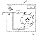
- Fig. 1 shows a cleaning device 2 designed as a washing machine.
- the cleaning device 2 has a cleaning room 4 with a rotatable laundry drum 6.
- the laundry drum can be set in rotation via a drive (arrow 8).
- the cleaning device 2 furthermore has a water inflow 10 which is fed via an external water supply 12.
- the water can be introduced into the cleaning space 4 via the water inflow 10 (arrow 14).
- the cleaning device 2 also has a water drain 16, via which the water can be discharged from the cleaning room 4 (arrow 18). The discharged water can then at least with a pump 20 partially returned to the water inflow 10 and thus reintroduced into the cleaning room 4.
- the cleaning device 2 also has a cleaning agent feed 22, with which a cleaning agent can be introduced from a reservoir 24 into the water flowing through the water inflow 10 and thus into the cleaning space 4.
- the cleaning device 2 also has a control device 26 for carrying out a cleaning process in the cleaning room 4.
- the control device 26 contains an electrical circuit with a processor, a memory and an input device, wherein various cleaning programs are stored on the memory, from which a user can select using the input device.
- An application unit 28 is integrated into the water inflow 10 of the cleaning device 2, the structure of which is shown in detail in Fig. 2 is shown.
- the application unit 28 has a line section 30 with an inlet 32 and an outlet 34.
- the inlet 32 and the outlet 34 are connected to the water inflow 10 such that the water from the water inflow 10 can flow through the inlet 32 into the line section 30 and out through the outlet 34 and back into the water inflow 10.
- the application unit also has a plasma source 36, which in the present case is designed as a plasma nozzle 38 for generating an atmospheric plasma jet 40.
- the plasma nozzle 38 has a metal nozzle tube 42 that tapers conically to a nozzle opening 44. At the end opposite the nozzle opening 44, the nozzle tube 42 has a swirl device 46 with an inlet 48 for a working gas, for example air.
- a working gas for example air.
- An intermediate wall 50 of the swirl device 46 has a ring of bores 52 made obliquely in the circumferential direction, through which the working gas is swirled.
- the downstream, conically tapered part of the nozzle tube is therefore flowed through by the working gas in the form of a vortex 54, the core of which runs on the longitudinal axis of the nozzle tube.
- An electrode 56 is arranged centrally on the underside of the intermediate wall 50 and projects coaxially in the direction of the tapered section into the nozzle tube.
- the electrode 56 is electrically connected to the intermediate wall 50 and the other parts of the swirl device 46.
- the swirl device 46 is electrically insulated from the nozzle tube 42 by a ceramic tube 58.
- a high-frequency high voltage which is generated by a transformer 60, is applied to the electrode 56 via the swirl device 46.
- the inlet 48 is connected via a hose, not shown, to a pressurized working gas source with variable throughput.
- the nozzle tube 42 is grounded.
- a high-frequency discharge in the form of an arc 62 is generated between the electrode 56 and the nozzle tube 42 by the applied voltage.
- arc is used here as a phenomenological description of the discharge, since the discharge occurs in the form of an arc.
- the term “arc” is understood in the case of direct voltage discharge with essentially constant voltage values.
- the outlet pipe 64 of the plasma nozzle 38 is guided through the wall of the line section 30 and is arranged such that the outlet opening 66 is submerged when water is passed through the line section 30.
- the plasma jet 40 emerging from the outlet opening 66 has a high reactivity and generates 68 reactive substances in the water, in particular reactive oxygen-containing substances, which accumulate in the form of bubbles 70 in particular in the water.
- the bubbles 70 are in Fig. 2 shown greatly enlarged for better illustration.
- the water 68 enriched with the reactive substances can then be introduced via the outlet 34 into the water inflow 10 and above into the cleaning room 4.
- the reactive substances in the water 68 lead to an improved cleaning effect there.
- the control device 26 is connected to the plasma nozzle 38 and is set up to control the plasma nozzle 38.
- the control device 26 also has a regulating device for regulating the temperature within the plasma nozzle 38 and / or the temperature of the plasma jet 40.
- thermocouples for measuring the temperature of the plasma jet 40 or the plasma nozzle 38 can be provided in the region of the plasma nozzle 38.
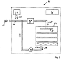
- Fig. 3 shows a cleaning device 82 designed as a dishwasher.
- the cleaning device 82 has a structure similar to that of the cleaning device 2 Fig. 1 ,
- the same components are identified with the same reference numerals. For the functionality of these same components, refer to the description Fig. 1 directed.
- the cleaning device 82 has, as the cleaning space 84, a space in which crockery, cutlery or devices, such as medical devices, can be arranged. At least one rotatable spray arm 86 is provided in the cleaning space 84, via which the water introduced into the cleaning space 84 through the water inflow 10 can be distributed therein.
- the cleaning device 82 also has an application unit 28, as shown in FIG Fig. 2 is shown.
- the application unit 28 the water is enriched by the plasma nozzle 38 with reactive substances, which lead to an improved cleaning effect in the cleaning room 84, so that the arranged in the cleaning room cleaning objects can be cleaned or disinfected better.
- Fig. 4 shows an application unit 102 according to a further exemplary embodiment of the cleaning device according to the invention, the method according to the invention and the use according to the invention.
- the application unit 102 has a structure similar to that of the application unit 28 Fig. 2 , The same components are identified with the same reference numerals.
- the application unit 102 can be used, for example, in the cleaning devices 2 and 82 instead of the application unit 28.
- the application unit 102 also has a plasma nozzle 38 as the plasma source.
- a plasma nozzle 38 as the plasma source.
- the application unit 102 differs from the application unit 28 in that a cage 104 is connected to the outlet pipe 64, into which the plasma jet 40 emerging from the outlet opening 66 enters.
- the reactive substances generated with the plasma jet 40 then enter the water through the openings 106 of the cage 104.
- direct contact of the plasma jet 66 with the water outside the cage 104 can be reduced or avoided.
- the excited working gas acts on the water around the plasma jet 66 and thus indirectly through the plasma jet.
- the working gas excited by the plasma jet 66 can also be regarded as plasma.
- Fig. 5 shows an application unit 112 according to a further exemplary embodiment of the cleaning device according to the invention, the method according to the invention and the use according to the invention.
- the application unit 112 has a structure similar to that of the application unit 28 Fig. 2 , The same components are identified with the same reference numerals.
- the application unit 112 can be used, for example, in the cleaning devices 2 and 82 instead of the application unit 28.
- the application unit 112 has a plasma nozzle 114 as a plasma source, which has a similar structure to that of the plasma nozzle 38 Fig. 2 , With regard to the same components, reference is therefore made to the description Fig. 2 directed.
- the application unit 112 differs from the application unit 28 in that the nozzle tube 42 and the outlet tube 64 are insulated on the inside with insulation 116 and in that the line section 30 is grounded instead of the nozzle tube 42.
- the plasma nozzle 114 is operated so that the water which in Fig. 5 As far as into the outlet pipe 64, acts as a second electrode for the arc 62.
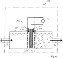
- Fig. 6 shows an application unit 122 not according to the invention.
- the application unit 122 has a structure which at least partially corresponds to that Structure of the application unit 28 from Fig. 2 similar.
- the same components are identified with the same reference numerals.
- the application unit 122 can be used for example in the cleaning devices 2 and 82 instead of the application unit 28.
- the application unit 122 differs from the application unit 28 in that, instead of a plasma nozzle, a plasma source 124 is provided for generating a plasma by means of dielectric barrier discharge.
- the plasma source 124 comprises a central electrode 126 with a dielectric coating 128 and a cage electrode 130 arranged around it.
- a high-frequency high voltage is applied between the central electrode 126 and the cage electrode 130 by means of a transformer 60.
- a working gas is blown in between the central electrode 126 and the cage electrode 130 (see arrows 132).
- the dielectric coating 128 prevents the formation of an arc discharge and instead leads to a dielectric barrier discharge between the central electrode 126 and the cage electrode 130. This creates a plasma between the electrode 126 and the cage electrode 130 and thus reactive substances which are enriched in the water.
- Fig. 7 shows an application unit 142 according to a further exemplary embodiment of the cleaning device according to the invention, the method according to the invention and the use according to the invention.
- the application unit 142 has a structure that at least partially comprises the configuration of the application unit 28 Fig. 2 similar.
- the same components are correspondingly the same Reference numbers marked.
- the application unit 142 can, for example, be used in the cleaning devices 2 and 82 instead of the application unit 28.
- the application unit 102 has a plasma nozzle 38 as the plasma source.
- a plasma nozzle 38 as the plasma source.
- a nozzle 144 is arranged behind the inlet 32, with which the water supplied via the inlet 32 can be atomized into droplets 146.
- the nozzle 144 is arranged in such a way that the droplets reach the area of the plasma jet 40 and are enriched there with reactive substances. Due to the large specific surface area of the droplets, an effective enrichment can be achieved.
- the droplets then precipitate again as liquid 148 and then return to the water inflow 10 through the outlet 34.
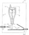
- Fig. 8 shows an application unit 162 not according to the invention.
- the application unit 162 like the application unit in FIG Fig. 2 an inlet 32 and an outlet 34.
- the application unit 162 can be used, for example, in the cleaning devices 2 and 82 instead of the application unit 28.
- the loading unit 162 has a first and a second reservoir 164a, 164b, a first and a second roller 166a, 166b and a third reservoir 168. Between A high-frequency high voltage is applied to the first and second rollers 166a, 166b by means of a transformer 60.
- the water supplied through inlet 32 is supplied to first and second reservoirs 164a and 164b.
- the supply is preferably carried out in such a way that the water in the first reservoir and the water in the second reservoir are galvanically separated from one another.
- Fig. 8 can be achieved by dripping 170a, 170b of the water.
- the water from the first and second reservoirs 164a, 164b flows like a waterfall over the first and second rollers 166a, 166b.
- the high-frequency high voltage between the rollers 166a, 166b leads to discharges between the water flowing over the first and the second rollers 166a, 166b.
- the water flowing over the first roller 166a and over the second roller 166b functions here as the first and second electrodes, respectively.
- the discharge creates a plasma in the area of the water, through which reactive substances are enriched in the water.
- a working gas (arrow 172) can preferably be blown between the rollers 166a, 166b.
- the water flowing over the rollers 166a, 166b reaches the third reservoir 168, preferably via a droplet 174a, 174b.
- the water can be returned to the water inflow via the outlet 34.
- FIG. 9a and 9b show an application unit 182 according to a further exemplary embodiment of the cleaning device according to the invention, of the method according to the invention and the use according to the invention.
- Fig. 9b shows a section through the in Fig. 9a appropriately marked level.
- the application unit 182 forms a unit with a pump 184, which, for example, in the
- Cleaning devices 2 and 82 can be used instead of the pump 20.
- the application unit 28 can then preferably be dispensed with.
- the pump 184 is in 9a and 9b designed as a centrifugal pump.
- the pump 184 has an inlet 186 and an outlet 188 as well as a pump housing 190, in which a paddle wheel 196 connected to a motor 194 via a shaft 192 is rotatably arranged. The rotation of the paddle wheel 196 pumps the water from the inlet 186 to the outlet 188.
- a plasma source 198 is connected to the pump 184 and can be designed as a plasma nozzle for generating a plasma jet.
- the plasma preferably one or more plasma jets
- the plasma can pass from the plasma source 198 into the pump housing 190, so that the water pumped in the pump housing 190 acts on the plasma and thereby reacts with it Substances is enriched.
- the rotation of the paddle wheel 196 leads to a good mixing of the reactive substances in the water.
- the present disclosure furthermore relates to a method in which a liquid is fed to a chemical process, in particular a combustion or (as a starting material) a chemical production process, and in which the liquid is fed to the chemical process before it is fed a plasma, in particular a plasma jet, is applied.
- a plasma in particular a plasma jet
- reactive substances can be accumulated in the liquid, by means of which the reaction can be improved, for example accelerated.
- the exposure to the plasma can thus serve as a catalyst, as it were, or replace or support a catalyst.
- the plasma sources previously described in this disclosure come into consideration as the plasma source.
- the plasma may also be exposed to the liquid as previously described in this disclosure.
- a fuel or fuel for example gasoline, diesel or kerosene
- plasma in particular before the fuel is burned in an internal combustion engine or in a jet engine.
- the application of plasma can be provided, for example, in, before or after a carburetor. As a result, the combustion of the fuel can be improved and the efficiency of the engine or the engine can be increased.
- a liquid educt for a chemical reaction preferably with at least one second educt, is subjected to plasma before the reaction.
- the plasma can provide the energy required to initiate the reaction in the liquid.
- the reaction can be accelerated or improved by the reactive substances in the liquid.
- the liquid can in principle also be a mixture, in particular a solution or a dispersion.
Landscapes
- Engineering & Computer Science (AREA)
- Physics & Mathematics (AREA)
- Plasma & Fusion (AREA)
- Spectroscopy & Molecular Physics (AREA)
- Textile Engineering (AREA)
- Cleaning By Liquid Or Steam (AREA)
Priority Applications (2)
| Application Number | Priority Date | Filing Date | Title |
|---|---|---|---|
| PL13818690T PL2931958T3 (pl) | 2012-12-11 | 2013-12-09 | Urządzenie czyszczące i sposób czyszczenia przedmiotów wodą |
| SI201331697T SI2931958T1 (sl) | 2012-12-11 | 2013-12-09 | Čistilna naprava in postopek za čiščenje predmetov z vodo |
Applications Claiming Priority (2)
| Application Number | Priority Date | Filing Date | Title |
|---|---|---|---|
| DE102012112094 | 2012-12-11 | ||
| PCT/EP2013/075987 WO2014090755A1 (de) | 2012-12-11 | 2013-12-09 | Reinigungsvorrichtung und verfahren zur reinigung von gegenständen mit wasser |
Publications (2)
| Publication Number | Publication Date |
|---|---|
| EP2931958A1 EP2931958A1 (de) | 2015-10-21 |
| EP2931958B1 true EP2931958B1 (de) | 2020-01-22 |
Family
ID=49943320
Family Applications (1)
| Application Number | Title | Priority Date | Filing Date |
|---|---|---|---|
| EP13818690.3A Active EP2931958B1 (de) | 2012-12-11 | 2013-12-09 | Reinigungsvorrichtung und verfahren zur reinigung von gegenständen mit wasser |
Country Status (4)
| Country | Link |
|---|---|
| EP (1) | EP2931958B1 (pl) |
| PL (1) | PL2931958T3 (pl) |
| SI (1) | SI2931958T1 (pl) |
| WO (1) | WO2014090755A1 (pl) |
Families Citing this family (6)
| Publication number | Priority date | Publication date | Assignee | Title |
|---|---|---|---|---|
| DE102015218930A1 (de) | 2015-09-30 | 2017-03-30 | Plasmatreat Gmbh | Aktiv-Nassdampf-Verfahren für Dampfturbinen und Dampfturbine mit Aktiv-Nassdampf-Vorrichtung |
| DE202017103504U1 (de) | 2017-06-12 | 2018-09-13 | Plasmatreat Gmbh | Waschmaschine |
| EP3415069A1 (en) * | 2017-06-16 | 2018-12-19 | Sanhua AWECO Appliance Systems GmbH | Plasma activated water for disinfecting home appliances |
| DE102018118067A1 (de) | 2018-07-26 | 2020-01-30 | Ecoclean Gmbh | Reinigungsvorrichtung |
| WO2020169572A1 (de) * | 2019-02-19 | 2020-08-27 | Fraunhofer-Gesellschaft zur Förderung der angewandten Forschung e. V. | Vorrichtung zum reinigen und/oder desinfizieren von haushaltsgebrauchsgegenständen |
| DE102023136302A1 (de) * | 2023-09-28 | 2025-04-03 | Plasmatreat Gmbh | Verfahren und vorrichtung zur reinigung von wäsche sowie verfahren und vorrichtung zur herstellung von plasmaaktivierter flüssigkeit |
Family Cites Families (3)
| Publication number | Priority date | Publication date | Assignee | Title |
|---|---|---|---|---|
| US5181399A (en) * | 1991-02-26 | 1993-01-26 | Tri-O-Clean Laundry Systems, Inc. | Laundry waste water treatment and wash apparatus |
| US20040206133A1 (en) * | 2003-04-19 | 2004-10-21 | Kyung-Chul Woo | Washing machine |
| AU2006202541A1 (en) * | 2006-06-15 | 2008-01-10 | Ozone Technologies Pty Limited | System and Device for Introducing Ozone into a Washing Apparatus |
-
2013
- 2013-12-09 WO PCT/EP2013/075987 patent/WO2014090755A1/de not_active Ceased
- 2013-12-09 EP EP13818690.3A patent/EP2931958B1/de active Active
- 2013-12-09 PL PL13818690T patent/PL2931958T3/pl unknown
- 2013-12-09 SI SI201331697T patent/SI2931958T1/sl unknown
Non-Patent Citations (1)
| Title |
|---|
| None * |
Also Published As
| Publication number | Publication date |
|---|---|
| SI2931958T1 (sl) | 2020-04-30 |
| WO2014090755A1 (de) | 2014-06-19 |
| EP2931958A1 (de) | 2015-10-21 |
| PL2931958T3 (pl) | 2020-07-13 |
Similar Documents
| Publication | Publication Date | Title |
|---|---|---|
| EP2931958B1 (de) | Reinigungsvorrichtung und verfahren zur reinigung von gegenständen mit wasser | |
| EP2598683B1 (de) | Hausgerät mit einem ozongenerator | |
| EP2440106A1 (de) | Hausgerät mit einem ozongenerator und einer ozonbeseitigungsvorrichtung, sowie zugehöriges verfahren | |
| EP1965833B1 (de) | Verfahren zur desinfektion von gegenständen | |
| EP2427595A1 (de) | Wäschebehandlungsgerät mit einem dampferzeuger sowie verfahren zum behandeln eines waschguts | |
| DE4440813C2 (de) | Verfahren zur Behandlung von Flüssigkeiten sowie Vorrichtung zur Durchführung des Verfahrens | |
| EP2794976B1 (de) | Verfahren zum betrieb eines haushaltsgeräts mit einem speicherbehälter und einem oxidationsmittelgenerator sowie hierfür geeignetes haushaltsgerät | |
| DE102012209211A1 (de) | Wasserführendes Haushaltsgerät mit einem Behandlungsgasgenerator und einer Einspülanordnung | |
| WO2012013541A1 (de) | Hausgerät mit einem ozongenerator | |
| DE102015208378A1 (de) | Wäschepflegegerät mit einem Radiallüfter | |
| DE102010030441B4 (de) | Verfahren zur Bestimmung von wäschespezifischen Eigenschaften in einem Wäschebehandlungsgerät und hierfür geeignetes Wäschebehandlungsgerät | |
| DE202017103504U1 (de) | Waschmaschine | |
| EP2759633B1 (de) | Haushaltsgerät mit katalytischer Reinigung | |
| DE102013224520B4 (de) | Wasserführendes Haushaltsgerät mit einem Speicherbehälter zur Speicherung von Grauwasser | |
| WO2021191040A1 (de) | Vorrichtung zur desinfektion von gegenständen oder feststoffen, vorzugsweise von schutzausrüstungsteilen, und deren verwendung | |
| EP3126559B1 (de) | Waschmaschine mit entfärbungsreservoir sowie verfahren zum waschen von textilien in einer solchen waschmaschine | |
| DE102014220355B3 (de) | Wäschepflegegerät mit einer Ozonerzeugungseinrichtung | |
| WO2003008698A1 (de) | Verfahren und vorrichtung für die antibakterielle chemische reinigung von textilien | |
| DE102023136302A1 (de) | Verfahren und vorrichtung zur reinigung von wäsche sowie verfahren und vorrichtung zur herstellung von plasmaaktivierter flüssigkeit | |
| DE102010027796A1 (de) | Waschmaschine mit einer Gasbeseitigungsvorrichtung und Verfahren zu ihrem Betrieb | |
| DE102016200602A1 (de) | Wäschepflegegerät mit einem Substanzbehälter | |
| EP1935312A2 (de) | Geschirrspülmaschine, insbesondere Haushalts-Geschirrspülmaschine, mit einer Einrichtung zum verbesserten Schmutzabtrag | |
| EP4006226B1 (de) | Haushaltsgerät zum behandeln von behandlungsgut, umfassend einen nebelerzeuger | |
| WO2020169572A1 (de) | Vorrichtung zum reinigen und/oder desinfizieren von haushaltsgebrauchsgegenständen | |
| DE102019106150A1 (de) | Verfahren und Einrichtung zur Reduzierung der Anzahl biologisch aktiver Mikroorganismen in Betriebsflüssigkeit |
Legal Events
| Date | Code | Title | Description |
|---|---|---|---|
| PUAI | Public reference made under article 153(3) epc to a published international application that has entered the european phase |
Free format text: ORIGINAL CODE: 0009012 |
|
| 17P | Request for examination filed |
Effective date: 20150609 |
|
| AK | Designated contracting states |
Kind code of ref document: A1 Designated state(s): AL AT BE BG CH CY CZ DE DK EE ES FI FR GB GR HR HU IE IS IT LI LT LU LV MC MK MT NL NO PL PT RO RS SE SI SK SM TR |
|
| AX | Request for extension of the european patent |
Extension state: BA ME |
|
| DAX | Request for extension of the european patent (deleted) | ||
| RAP1 | Party data changed (applicant data changed or rights of an application transferred) |
Owner name: PLASMATREAT GMBH |
|
| RIN1 | Information on inventor provided before grant (corrected) |
Inventor name: PLASMATREAT GMBH |
|
| RIC1 | Information provided on ipc code assigned before grant |
Ipc: D06F 35/00 20060101AFI20190513BHEP Ipc: B08B 7/00 20060101ALI20190513BHEP Ipc: B08B 3/10 20060101ALN20190513BHEP Ipc: H05H 1/48 20060101ALN20190513BHEP |
|
| RIC1 | Information provided on ipc code assigned before grant |
Ipc: H05H 1/48 20060101ALN20190517BHEP Ipc: D06F 35/00 20060101AFI20190517BHEP Ipc: B08B 7/00 20060101ALI20190517BHEP Ipc: B08B 3/10 20060101ALN20190517BHEP |
|
| GRAP | Despatch of communication of intention to grant a patent |
Free format text: ORIGINAL CODE: EPIDOSNIGR1 |
|
| STAA | Information on the status of an ep patent application or granted ep patent |
Free format text: STATUS: GRANT OF PATENT IS INTENDED |
|
| INTG | Intention to grant announced |
Effective date: 20190703 |
|
| RIN1 | Information on inventor provided before grant (corrected) |
Inventor name: BUSKE, CHRISTIANE |
|
| GRAS | Grant fee paid |
Free format text: ORIGINAL CODE: EPIDOSNIGR3 |
|
| GRAA | (expected) grant |
Free format text: ORIGINAL CODE: 0009210 |
|
| STAA | Information on the status of an ep patent application or granted ep patent |
Free format text: STATUS: THE PATENT HAS BEEN GRANTED |
|
| AK | Designated contracting states |
Kind code of ref document: B1 Designated state(s): AL AT BE BG CH CY CZ DE DK EE ES FI FR GB GR HR HU IE IS IT LI LT LU LV MC MK MT NL NO PL PT RO RS SE SI SK SM TR |
|
| REG | Reference to a national code |
Ref country code: GB Ref legal event code: FG4D Free format text: NOT ENGLISH |
|
| REG | Reference to a national code |
Ref country code: CH Ref legal event code: EP |
|
| REG | Reference to a national code |
Ref country code: DE Ref legal event code: R096 Ref document number: 502013014258 Country of ref document: DE |
|
| REG | Reference to a national code |
Ref country code: AT Ref legal event code: REF Ref document number: 1226961 Country of ref document: AT Kind code of ref document: T Effective date: 20200215 |
|
| REG | Reference to a national code |
Ref country code: IE Ref legal event code: FG4D Free format text: LANGUAGE OF EP DOCUMENT: GERMAN |
|
| REG | Reference to a national code |
Ref country code: NL Ref legal event code: MP Effective date: 20200122 |
|
| REG | Reference to a national code |
Ref country code: LT Ref legal event code: MG4D |
|
| PG25 | Lapsed in a contracting state [announced via postgrant information from national office to epo] |
Ref country code: RS Free format text: LAPSE BECAUSE OF FAILURE TO SUBMIT A TRANSLATION OF THE DESCRIPTION OR TO PAY THE FEE WITHIN THE PRESCRIBED TIME-LIMIT Effective date: 20200122 Ref country code: NL Free format text: LAPSE BECAUSE OF FAILURE TO SUBMIT A TRANSLATION OF THE DESCRIPTION OR TO PAY THE FEE WITHIN THE PRESCRIBED TIME-LIMIT Effective date: 20200122 Ref country code: FI Free format text: LAPSE BECAUSE OF FAILURE TO SUBMIT A TRANSLATION OF THE DESCRIPTION OR TO PAY THE FEE WITHIN THE PRESCRIBED TIME-LIMIT Effective date: 20200122 Ref country code: PT Free format text: LAPSE BECAUSE OF FAILURE TO SUBMIT A TRANSLATION OF THE DESCRIPTION OR TO PAY THE FEE WITHIN THE PRESCRIBED TIME-LIMIT Effective date: 20200614 Ref country code: NO Free format text: LAPSE BECAUSE OF FAILURE TO SUBMIT A TRANSLATION OF THE DESCRIPTION OR TO PAY THE FEE WITHIN THE PRESCRIBED TIME-LIMIT Effective date: 20200422 |
|
| PG25 | Lapsed in a contracting state [announced via postgrant information from national office to epo] |
Ref country code: LV Free format text: LAPSE BECAUSE OF FAILURE TO SUBMIT A TRANSLATION OF THE DESCRIPTION OR TO PAY THE FEE WITHIN THE PRESCRIBED TIME-LIMIT Effective date: 20200122 Ref country code: SE Free format text: LAPSE BECAUSE OF FAILURE TO SUBMIT A TRANSLATION OF THE DESCRIPTION OR TO PAY THE FEE WITHIN THE PRESCRIBED TIME-LIMIT Effective date: 20200122 Ref country code: BG Free format text: LAPSE BECAUSE OF FAILURE TO SUBMIT A TRANSLATION OF THE DESCRIPTION OR TO PAY THE FEE WITHIN THE PRESCRIBED TIME-LIMIT Effective date: 20200422 Ref country code: IS Free format text: LAPSE BECAUSE OF FAILURE TO SUBMIT A TRANSLATION OF THE DESCRIPTION OR TO PAY THE FEE WITHIN THE PRESCRIBED TIME-LIMIT Effective date: 20200522 Ref country code: GR Free format text: LAPSE BECAUSE OF FAILURE TO SUBMIT A TRANSLATION OF THE DESCRIPTION OR TO PAY THE FEE WITHIN THE PRESCRIBED TIME-LIMIT Effective date: 20200423 Ref country code: HR Free format text: LAPSE BECAUSE OF FAILURE TO SUBMIT A TRANSLATION OF THE DESCRIPTION OR TO PAY THE FEE WITHIN THE PRESCRIBED TIME-LIMIT Effective date: 20200122 |
|
| REG | Reference to a national code |
Ref country code: DE Ref legal event code: R097 Ref document number: 502013014258 Country of ref document: DE |
|
| PG25 | Lapsed in a contracting state [announced via postgrant information from national office to epo] |
Ref country code: CZ Free format text: LAPSE BECAUSE OF FAILURE TO SUBMIT A TRANSLATION OF THE DESCRIPTION OR TO PAY THE FEE WITHIN THE PRESCRIBED TIME-LIMIT Effective date: 20200122 Ref country code: RO Free format text: LAPSE BECAUSE OF FAILURE TO SUBMIT A TRANSLATION OF THE DESCRIPTION OR TO PAY THE FEE WITHIN THE PRESCRIBED TIME-LIMIT Effective date: 20200122 Ref country code: SK Free format text: LAPSE BECAUSE OF FAILURE TO SUBMIT A TRANSLATION OF THE DESCRIPTION OR TO PAY THE FEE WITHIN THE PRESCRIBED TIME-LIMIT Effective date: 20200122 Ref country code: SM Free format text: LAPSE BECAUSE OF FAILURE TO SUBMIT A TRANSLATION OF THE DESCRIPTION OR TO PAY THE FEE WITHIN THE PRESCRIBED TIME-LIMIT Effective date: 20200122 Ref country code: DK Free format text: LAPSE BECAUSE OF FAILURE TO SUBMIT A TRANSLATION OF THE DESCRIPTION OR TO PAY THE FEE WITHIN THE PRESCRIBED TIME-LIMIT Effective date: 20200122 Ref country code: EE Free format text: LAPSE BECAUSE OF FAILURE TO SUBMIT A TRANSLATION OF THE DESCRIPTION OR TO PAY THE FEE WITHIN THE PRESCRIBED TIME-LIMIT Effective date: 20200122 Ref country code: LT Free format text: LAPSE BECAUSE OF FAILURE TO SUBMIT A TRANSLATION OF THE DESCRIPTION OR TO PAY THE FEE WITHIN THE PRESCRIBED TIME-LIMIT Effective date: 20200122 Ref country code: ES Free format text: LAPSE BECAUSE OF FAILURE TO SUBMIT A TRANSLATION OF THE DESCRIPTION OR TO PAY THE FEE WITHIN THE PRESCRIBED TIME-LIMIT Effective date: 20200122 |
|
| PLBE | No opposition filed within time limit |
Free format text: ORIGINAL CODE: 0009261 |
|
| STAA | Information on the status of an ep patent application or granted ep patent |
Free format text: STATUS: NO OPPOSITION FILED WITHIN TIME LIMIT |
|
| 26N | No opposition filed |
Effective date: 20201023 |
|
| REG | Reference to a national code |
Ref country code: CH Ref legal event code: PL |
|
| PG25 | Lapsed in a contracting state [announced via postgrant information from national office to epo] |
Ref country code: MC Free format text: LAPSE BECAUSE OF FAILURE TO SUBMIT A TRANSLATION OF THE DESCRIPTION OR TO PAY THE FEE WITHIN THE PRESCRIBED TIME-LIMIT Effective date: 20200122 |
|
| PG25 | Lapsed in a contracting state [announced via postgrant information from national office to epo] |
Ref country code: IE Free format text: LAPSE BECAUSE OF NON-PAYMENT OF DUE FEES Effective date: 20201209 Ref country code: LU Free format text: LAPSE BECAUSE OF NON-PAYMENT OF DUE FEES Effective date: 20201209 |
|
| PG25 | Lapsed in a contracting state [announced via postgrant information from national office to epo] |
Ref country code: CH Free format text: LAPSE BECAUSE OF NON-PAYMENT OF DUE FEES Effective date: 20201231 Ref country code: LI Free format text: LAPSE BECAUSE OF NON-PAYMENT OF DUE FEES Effective date: 20201231 |
|
| PG25 | Lapsed in a contracting state [announced via postgrant information from national office to epo] |
Ref country code: TR Free format text: LAPSE BECAUSE OF FAILURE TO SUBMIT A TRANSLATION OF THE DESCRIPTION OR TO PAY THE FEE WITHIN THE PRESCRIBED TIME-LIMIT Effective date: 20200122 Ref country code: MT Free format text: LAPSE BECAUSE OF FAILURE TO SUBMIT A TRANSLATION OF THE DESCRIPTION OR TO PAY THE FEE WITHIN THE PRESCRIBED TIME-LIMIT Effective date: 20200122 Ref country code: CY Free format text: LAPSE BECAUSE OF FAILURE TO SUBMIT A TRANSLATION OF THE DESCRIPTION OR TO PAY THE FEE WITHIN THE PRESCRIBED TIME-LIMIT Effective date: 20200122 |
|
| PG25 | Lapsed in a contracting state [announced via postgrant information from national office to epo] |
Ref country code: MK Free format text: LAPSE BECAUSE OF FAILURE TO SUBMIT A TRANSLATION OF THE DESCRIPTION OR TO PAY THE FEE WITHIN THE PRESCRIBED TIME-LIMIT Effective date: 20200122 Ref country code: AL Free format text: LAPSE BECAUSE OF FAILURE TO SUBMIT A TRANSLATION OF THE DESCRIPTION OR TO PAY THE FEE WITHIN THE PRESCRIBED TIME-LIMIT Effective date: 20200122 |
|
| PGFP | Annual fee paid to national office [announced via postgrant information from national office to epo] |
Ref country code: GB Payment date: 20221219 Year of fee payment: 10 Ref country code: FR Payment date: 20221216 Year of fee payment: 10 Ref country code: DE Payment date: 20221216 Year of fee payment: 10 Ref country code: AT Payment date: 20221219 Year of fee payment: 10 |
|
| PGFP | Annual fee paid to national office [announced via postgrant information from national office to epo] |
Ref country code: BE Payment date: 20221219 Year of fee payment: 10 |
|
| PGFP | Annual fee paid to national office [announced via postgrant information from national office to epo] |
Ref country code: IT Payment date: 20221220 Year of fee payment: 10 |
|
| PGFP | Annual fee paid to national office [announced via postgrant information from national office to epo] |
Ref country code: SI Payment date: 20231102 Year of fee payment: 11 |
|
| PGFP | Annual fee paid to national office [announced via postgrant information from national office to epo] |
Ref country code: PL Payment date: 20231205 Year of fee payment: 11 |
|
| REG | Reference to a national code |
Ref country code: DE Ref legal event code: R119 Ref document number: 502013014258 Country of ref document: DE |
|
| REG | Reference to a national code |
Ref country code: AT Ref legal event code: MM01 Ref document number: 1226961 Country of ref document: AT Kind code of ref document: T Effective date: 20231209 |
|
| GBPC | Gb: european patent ceased through non-payment of renewal fee |
Effective date: 20231209 |
|
| REG | Reference to a national code |
Ref country code: BE Ref legal event code: MM Effective date: 20231231 |
|
| PG25 | Lapsed in a contracting state [announced via postgrant information from national office to epo] |
Ref country code: DE Free format text: LAPSE BECAUSE OF NON-PAYMENT OF DUE FEES Effective date: 20240702 |
|
| PG25 | Lapsed in a contracting state [announced via postgrant information from national office to epo] |
Ref country code: GB Free format text: LAPSE BECAUSE OF NON-PAYMENT OF DUE FEES Effective date: 20231209 |
|
| PG25 | Lapsed in a contracting state [announced via postgrant information from national office to epo] |
Ref country code: BE Free format text: LAPSE BECAUSE OF NON-PAYMENT OF DUE FEES Effective date: 20231231 |
|
| PG25 | Lapsed in a contracting state [announced via postgrant information from national office to epo] |
Ref country code: FR Free format text: LAPSE BECAUSE OF NON-PAYMENT OF DUE FEES Effective date: 20231231 |
|
| PG25 | Lapsed in a contracting state [announced via postgrant information from national office to epo] |
Ref country code: AT Free format text: LAPSE BECAUSE OF NON-PAYMENT OF DUE FEES Effective date: 20231209 |
|
| PG25 | Lapsed in a contracting state [announced via postgrant information from national office to epo] |
Ref country code: GB Free format text: LAPSE BECAUSE OF NON-PAYMENT OF DUE FEES Effective date: 20231209 Ref country code: FR Free format text: LAPSE BECAUSE OF NON-PAYMENT OF DUE FEES Effective date: 20231231 Ref country code: DE Free format text: LAPSE BECAUSE OF NON-PAYMENT OF DUE FEES Effective date: 20240702 Ref country code: BE Free format text: LAPSE BECAUSE OF NON-PAYMENT OF DUE FEES Effective date: 20231231 Ref country code: AT Free format text: LAPSE BECAUSE OF NON-PAYMENT OF DUE FEES Effective date: 20231209 |
|
| PG25 | Lapsed in a contracting state [announced via postgrant information from national office to epo] |
Ref country code: IT Free format text: LAPSE BECAUSE OF NON-PAYMENT OF DUE FEES Effective date: 20231209 |
|
| REG | Reference to a national code |
Ref country code: SI Ref legal event code: KO00 Effective date: 20241210 |