EP2931437B1 - System mit zwei erhitzern für eine sprühdose - Google Patents
System mit zwei erhitzern für eine sprühdose Download PDFInfo
- Publication number
- EP2931437B1 EP2931437B1 EP13866372.9A EP13866372A EP2931437B1 EP 2931437 B1 EP2931437 B1 EP 2931437B1 EP 13866372 A EP13866372 A EP 13866372A EP 2931437 B1 EP2931437 B1 EP 2931437B1
- Authority
- EP
- European Patent Office
- Prior art keywords
- heater
- power
- fluid
- pressure
- boost
- Prior art date
- Legal status (The legal status is an assumption and is not a legal conclusion. Google has not performed a legal analysis and makes no representation as to the accuracy of the status listed.)
- Active
Links
Images


Classifications
-
- B—PERFORMING OPERATIONS; TRANSPORTING
- B29—WORKING OF PLASTICS; WORKING OF SUBSTANCES IN A PLASTIC STATE IN GENERAL
- B29B—PREPARATION OR PRETREATMENT OF THE MATERIAL TO BE SHAPED; MAKING GRANULES OR PREFORMS; RECOVERY OF PLASTICS OR OTHER CONSTITUENTS OF WASTE MATERIAL CONTAINING PLASTICS
- B29B7/00—Mixing; Kneading
- B29B7/74—Mixing; Kneading using other mixers or combinations of mixers, e.g. of dissimilar mixers ; Plant
- B29B7/7438—Mixing guns, i.e. hand-held mixing units having dispensing means
- B29B7/7447—Mixing guns, i.e. hand-held mixing units having dispensing means including means for feeding the components
-
- B—PERFORMING OPERATIONS; TRANSPORTING
- B05—SPRAYING OR ATOMISING IN GENERAL; APPLYING FLUENT MATERIALS TO SURFACES, IN GENERAL
- B05B—SPRAYING APPARATUS; ATOMISING APPARATUS; NOZZLES
- B05B15/00—Details of spraying plant or spraying apparatus not otherwise provided for; Accessories
- B05B15/50—Arrangements for cleaning; Arrangements for preventing deposits, drying-out or blockage; Arrangements for detecting improper discharge caused by the presence of foreign matter
- B05B15/58—Arrangements for cleaning; Arrangements for preventing deposits, drying-out or blockage; Arrangements for detecting improper discharge caused by the presence of foreign matter preventing deposits, drying-out or blockage by recirculating the fluid to be sprayed from upstream of the discharge opening back to the supplying means
-
- B—PERFORMING OPERATIONS; TRANSPORTING
- B05—SPRAYING OR ATOMISING IN GENERAL; APPLYING FLUENT MATERIALS TO SURFACES, IN GENERAL
- B05B—SPRAYING APPARATUS; ATOMISING APPARATUS; NOZZLES
- B05B7/00—Spraying apparatus for discharge of liquids or other fluent materials from two or more sources, e.g. of liquid and air, of powder and gas
- B05B7/0093—At least a part of the apparatus, e.g. a container, being provided with means, e.g. wheels or casters for allowing its displacement relative to the ground
-
- B—PERFORMING OPERATIONS; TRANSPORTING
- B05—SPRAYING OR ATOMISING IN GENERAL; APPLYING FLUENT MATERIALS TO SURFACES, IN GENERAL
- B05B—SPRAYING APPARATUS; ATOMISING APPARATUS; NOZZLES
- B05B7/00—Spraying apparatus for discharge of liquids or other fluent materials from two or more sources, e.g. of liquid and air, of powder and gas
- B05B7/02—Spray pistols; Apparatus for discharge
- B05B7/04—Spray pistols; Apparatus for discharge with arrangements for mixing liquids or other fluent materials before discharge
- B05B7/0408—Spray pistols; Apparatus for discharge with arrangements for mixing liquids or other fluent materials before discharge with arrangements for mixing two or more liquids
-
- B—PERFORMING OPERATIONS; TRANSPORTING
- B05—SPRAYING OR ATOMISING IN GENERAL; APPLYING FLUENT MATERIALS TO SURFACES, IN GENERAL
- B05B—SPRAYING APPARATUS; ATOMISING APPARATUS; NOZZLES
- B05B7/00—Spraying apparatus for discharge of liquids or other fluent materials from two or more sources, e.g. of liquid and air, of powder and gas
- B05B7/02—Spray pistols; Apparatus for discharge
- B05B7/04—Spray pistols; Apparatus for discharge with arrangements for mixing liquids or other fluent materials before discharge
- B05B7/0416—Spray pistols; Apparatus for discharge with arrangements for mixing liquids or other fluent materials before discharge with arrangements for mixing one gas and one liquid
-
- B—PERFORMING OPERATIONS; TRANSPORTING
- B05—SPRAYING OR ATOMISING IN GENERAL; APPLYING FLUENT MATERIALS TO SURFACES, IN GENERAL
- B05B—SPRAYING APPARATUS; ATOMISING APPARATUS; NOZZLES
- B05B7/00—Spraying apparatus for discharge of liquids or other fluent materials from two or more sources, e.g. of liquid and air, of powder and gas
- B05B7/16—Spraying apparatus for discharge of liquids or other fluent materials from two or more sources, e.g. of liquid and air, of powder and gas incorporating means for heating or cooling the material to be sprayed
- B05B7/166—Spraying apparatus for discharge of liquids or other fluent materials from two or more sources, e.g. of liquid and air, of powder and gas incorporating means for heating or cooling the material to be sprayed the material to be sprayed being heated in a container
-
- B—PERFORMING OPERATIONS; TRANSPORTING
- B05—SPRAYING OR ATOMISING IN GENERAL; APPLYING FLUENT MATERIALS TO SURFACES, IN GENERAL
- B05B—SPRAYING APPARATUS; ATOMISING APPARATUS; NOZZLES
- B05B7/00—Spraying apparatus for discharge of liquids or other fluent materials from two or more sources, e.g. of liquid and air, of powder and gas
- B05B7/16—Spraying apparatus for discharge of liquids or other fluent materials from two or more sources, e.g. of liquid and air, of powder and gas incorporating means for heating or cooling the material to be sprayed
- B05B7/1693—Spraying apparatus for discharge of liquids or other fluent materials from two or more sources, e.g. of liquid and air, of powder and gas incorporating means for heating or cooling the material to be sprayed with means for heating the material to be sprayed or an atomizing fluid in a supply hose or the like
-
- B—PERFORMING OPERATIONS; TRANSPORTING
- B05—SPRAYING OR ATOMISING IN GENERAL; APPLYING FLUENT MATERIALS TO SURFACES, IN GENERAL
- B05B—SPRAYING APPARATUS; ATOMISING APPARATUS; NOZZLES
- B05B7/00—Spraying apparatus for discharge of liquids or other fluent materials from two or more sources, e.g. of liquid and air, of powder and gas
- B05B7/24—Spraying apparatus for discharge of liquids or other fluent materials from two or more sources, e.g. of liquid and air, of powder and gas with means, e.g. a container, for supplying liquid or other fluent material to a discharge device
- B05B7/2489—Spraying apparatus for discharge of liquids or other fluent materials from two or more sources, e.g. of liquid and air, of powder and gas with means, e.g. a container, for supplying liquid or other fluent material to a discharge device an atomising fluid, e.g. a gas, being supplied to the discharge device
- B05B7/2497—Spraying apparatus for discharge of liquids or other fluent materials from two or more sources, e.g. of liquid and air, of powder and gas with means, e.g. a container, for supplying liquid or other fluent material to a discharge device an atomising fluid, e.g. a gas, being supplied to the discharge device several liquids from different sources being supplied to the discharge device
-
- B—PERFORMING OPERATIONS; TRANSPORTING
- B05—SPRAYING OR ATOMISING IN GENERAL; APPLYING FLUENT MATERIALS TO SURFACES, IN GENERAL
- B05B—SPRAYING APPARATUS; ATOMISING APPARATUS; NOZZLES
- B05B9/00—Spraying apparatus for discharge of liquids or other fluent material, without essentially mixing with gas or vapour
- B05B9/002—Spraying apparatus for discharge of liquids or other fluent material, without essentially mixing with gas or vapour incorporating means for heating or cooling, e.g. the material to be sprayed
-
- B—PERFORMING OPERATIONS; TRANSPORTING
- B05—SPRAYING OR ATOMISING IN GENERAL; APPLYING FLUENT MATERIALS TO SURFACES, IN GENERAL
- B05D—PROCESSES FOR APPLYING FLUENT MATERIALS TO SURFACES, IN GENERAL
- B05D1/00—Processes for applying liquids or other fluent materials
- B05D1/02—Processes for applying liquids or other fluent materials performed by spraying
-
- B—PERFORMING OPERATIONS; TRANSPORTING
- B29—WORKING OF PLASTICS; WORKING OF SUBSTANCES IN A PLASTIC STATE IN GENERAL
- B29B—PREPARATION OR PRETREATMENT OF THE MATERIAL TO BE SHAPED; MAKING GRANULES OR PREFORMS; RECOVERY OF PLASTICS OR OTHER CONSTITUENTS OF WASTE MATERIAL CONTAINING PLASTICS
- B29B7/00—Mixing; Kneading
- B29B7/30—Mixing; Kneading continuous, with mechanical mixing or kneading devices
- B29B7/58—Component parts, details or accessories; Auxiliary operations
- B29B7/72—Measuring, controlling or regulating
- B29B7/726—Measuring properties of mixture, e.g. temperature or density
-
- B—PERFORMING OPERATIONS; TRANSPORTING
- B29—WORKING OF PLASTICS; WORKING OF SUBSTANCES IN A PLASTIC STATE IN GENERAL
- B29B—PREPARATION OR PRETREATMENT OF THE MATERIAL TO BE SHAPED; MAKING GRANULES OR PREFORMS; RECOVERY OF PLASTICS OR OTHER CONSTITUENTS OF WASTE MATERIAL CONTAINING PLASTICS
- B29B7/00—Mixing; Kneading
- B29B7/74—Mixing; Kneading using other mixers or combinations of mixers, e.g. of dissimilar mixers ; Plant
- B29B7/7404—Mixing devices specially adapted for foamable substances
- B29B7/7433—Plants
-
- B—PERFORMING OPERATIONS; TRANSPORTING
- B29—WORKING OF PLASTICS; WORKING OF SUBSTANCES IN A PLASTIC STATE IN GENERAL
- B29B—PREPARATION OR PRETREATMENT OF THE MATERIAL TO BE SHAPED; MAKING GRANULES OR PREFORMS; RECOVERY OF PLASTICS OR OTHER CONSTITUENTS OF WASTE MATERIAL CONTAINING PLASTICS
- B29B7/00—Mixing; Kneading
- B29B7/80—Component parts, details or accessories; Auxiliary operations
- B29B7/82—Heating or cooling
- B29B7/823—Temperature control
-
- B—PERFORMING OPERATIONS; TRANSPORTING
- B29—WORKING OF PLASTICS; WORKING OF SUBSTANCES IN A PLASTIC STATE IN GENERAL
- B29B—PREPARATION OR PRETREATMENT OF THE MATERIAL TO BE SHAPED; MAKING GRANULES OR PREFORMS; RECOVERY OF PLASTICS OR OTHER CONSTITUENTS OF WASTE MATERIAL CONTAINING PLASTICS
- B29B7/00—Mixing; Kneading
- B29B7/80—Component parts, details or accessories; Auxiliary operations
- B29B7/82—Heating or cooling
- B29B7/826—Apparatus therefor
-
- H—ELECTRICITY
- H05—ELECTRIC TECHNIQUES NOT OTHERWISE PROVIDED FOR
- H05B—ELECTRIC HEATING; ELECTRIC LIGHT SOURCES NOT OTHERWISE PROVIDED FOR; CIRCUIT ARRANGEMENTS FOR ELECTRIC LIGHT SOURCES, IN GENERAL
- H05B1/00—Details of electric heating devices
- H05B1/02—Automatic switching arrangements specially adapted to apparatus ; Control of heating devices
- H05B1/0202—Switches
-
- H—ELECTRICITY
- H05—ELECTRIC TECHNIQUES NOT OTHERWISE PROVIDED FOR
- H05B—ELECTRIC HEATING; ELECTRIC LIGHT SOURCES NOT OTHERWISE PROVIDED FOR; CIRCUIT ARRANGEMENTS FOR ELECTRIC LIGHT SOURCES, IN GENERAL
- H05B1/00—Details of electric heating devices
- H05B1/02—Automatic switching arrangements specially adapted to apparatus ; Control of heating devices
- H05B1/0227—Applications
- H05B1/023—Industrial applications
- H05B1/0244—Heating of fluids
-
- B—PERFORMING OPERATIONS; TRANSPORTING
- B05—SPRAYING OR ATOMISING IN GENERAL; APPLYING FLUENT MATERIALS TO SURFACES, IN GENERAL
- B05B—SPRAYING APPARATUS; ATOMISING APPARATUS; NOZZLES
- B05B9/00—Spraying apparatus for discharge of liquids or other fluent material, without essentially mixing with gas or vapour
- B05B9/03—Spraying apparatus for discharge of liquids or other fluent material, without essentially mixing with gas or vapour characterised by means for supplying liquid or other fluent material
- B05B9/04—Spraying apparatus for discharge of liquids or other fluent material, without essentially mixing with gas or vapour characterised by means for supplying liquid or other fluent material with pressurised or compressible container; with pump
- B05B9/06—Spraying apparatus for discharge of liquids or other fluent material, without essentially mixing with gas or vapour characterised by means for supplying liquid or other fluent material with pressurised or compressible container; with pump the delivery being related to the movement of a vehicle, e.g. the pump being driven by a vehicle wheel
-
- B—PERFORMING OPERATIONS; TRANSPORTING
- B05—SPRAYING OR ATOMISING IN GENERAL; APPLYING FLUENT MATERIALS TO SURFACES, IN GENERAL
- B05D—PROCESSES FOR APPLYING FLUENT MATERIALS TO SURFACES, IN GENERAL
- B05D1/00—Processes for applying liquids or other fluent materials
- B05D1/34—Applying different liquids or other fluent materials simultaneously
-
- B—PERFORMING OPERATIONS; TRANSPORTING
- B29—WORKING OF PLASTICS; WORKING OF SUBSTANCES IN A PLASTIC STATE IN GENERAL
- B29B—PREPARATION OR PRETREATMENT OF THE MATERIAL TO BE SHAPED; MAKING GRANULES OR PREFORMS; RECOVERY OF PLASTICS OR OTHER CONSTITUENTS OF WASTE MATERIAL CONTAINING PLASTICS
- B29B7/00—Mixing; Kneading
- B29B7/80—Component parts, details or accessories; Auxiliary operations
- B29B7/802—Constructions or methods for cleaning the mixing or kneading device
- B29B7/803—Cleaning of mixers of the gun type, stream-impigement type, mixing heads
- B29B7/806—Cleaning of the discharge opening, e.g. orifice of the dispenser
Definitions
- the present invention relates generally to spray dispensers that are used to apply polyurea coatings, polyurethane foam, and the like. More particularly, this invention relates to a heater system and heater control scheme for a mobile spray dispenser.
- Spray dispensers are used to apply a variety of materials.
- Spray dispensers for polyurea, polyurethane, and similar materials have separate “A-side” and “B-side” fluid systems with separate fluid reservoirs, pumps, fluid lines, and heaters.
- the separate “A-side” and “B-side” fluid systems carry different fluids, which are combined at a spray head to rapidly form foam or coatings.
- "A-side” fluids can include isocyanates, while “B-side” fluids can contain resins, polyol, flame retardants, and amine catalysts.
- the resulting mixture of "A-side” and “B-side” fluids typically cures in about ten seconds.
- A-side and “B-side fluids are mixed at a sprayer disposed to aerosolize the mixed fluids and dispense the aerosol mixture on a target surface.
- fluids in both sides are pressurized to a high pressure by separate pumps, and heated.
- Some spray dispensers heat fluids with dedicated heaters to reduce fluid viscosity, thereby improving fluid flow and increasing spray efficiency. Both heaters and pumps draw considerable power.
- US 4 809 909 discloses a plural component application system having a delivery system which delivers the components to a sprayer for mixing and dispensing.
- the delivery system is provided with positive displacement piston pumps simultaneously driven by a single motor, so as to continuously recirculate the components between the sprayer and component sources.
- the system is further provided with calibration means to enable the rates of flow of the components in the delivery system to be calibrated, and a chopper to direct reinforcing glass fibers into the component mixture dispensed from the sprayer.
- a mobile spray dispenser according to claim 1.
- a heater control method according to claim 14. Preferable features are set out in the dependent claims.
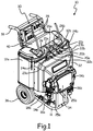
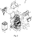
- FIGs. 1 and 2 are perspective and exploded perspective views, respectively, of spray dispenser 10.
- Spray dispenser 10 is a mobile applicator, e.g. for polyurethane foam or polyurea coatings.
- Spray dispenser 10 has separate A-side and B-side fluid systems with parallel components and architecture labeled as elements 12a, 14a, 16a, etc. for A-side components, and 12b, 14b, 16b, etc. for B-side components.
- Spray dispenser 10 comprises structural frame 11, reservoirs 12a and 12b, pumps 14a and 14b, fluid lines 16a and 16b, cutoff valve 18a, hose manifold 19 (with outlet hose connections 20a and 20b, recirculation valves 21a and 21b, return hose connections 22a and 22b, and recirculation hose connections 23a and 23b), reservoir ports 24a and 24b, inlet temperature gauges 25a and 25b, outlet pressure gauges 26a and 26b, primary controller 28, interface 30, heater system cover 32, pump system cover 34, wheels 36, handles 38, and storage tray 40. Secondary cover 42, motor 44, heater module 46, and heater control system 48 are visible in FIG. 2 , but not FIG. 1 , while some elements illustrated in both FIG. 1 and FIG. 2 are not relabeled in FIG. 2 , to improve legibility of FIG. 2 . FIGs. 1 and 2 are hereinafter discussed concurrently.
- Structural frame 11 is a rigid support structure to which all other elements of spray dispenser 10 are directly or indirectly attached.
- Reservoirs 12a and 12b are storage tanks for fluids that cure when combined.
- A-side reservoir 12a can, for instance, carry isocyanates, while B-side reservoir 12b can, for instance, carry resins, polyol, flame retardants, or amine catalysts.
- Pumps 14a and 14b are motorized pumps disposed to draw fluid from reservoirs 12a and 12b through fluid lines 16a and 16b so long as cutoff valve 18a remains open.
- Cutoff valve 18a can, for example, be a ball valve, butterfly valve, or similar valves disposed to interrupt fluid line 16a in a closed valve state.
- a parallel cutoff valve i.e.
- cutoff valve 18b is similarly disposed on fluid line 16b.
- Pumps 14a and 14b force fluid from fluid lines 16a and 16b through heaters (see heater module 46, described in detail below with respect to FIGs. 2-6 ) to outlet hose connections 20a and 20b, respectively, of hose manifold 19.
- Hose manifold 19 is a fluid routing structure comprising outlet hose connections 20a and 20b, recirculation valves 21a and 21b, return hose connections 22a and 22b, and recirculation hose connections 23a and 23b.
- Hose connections 20a, 20b, 22a, 22b, 23a, and 23b are hookup locations for flexible hoses.
- Outlet hose connections 20a and 20b attach to outlet hoses that deliver fluid from pumps 14a and 14b to sprayer 27 (see FIG. 3 ), which may be a handheld applicator or spray gun.
- Return hose connections 22a and 22b attach to return hoses that return unsprayed fluid from sprayer 27 to hose manifold 19.
- Recirculation valves 21a and 21b are cutoff valves that selectively allow or disallow fluid flow from return hose connections 22a and 22b to recirculation hose connections 23a and 23b, respectively.
- Recirculation hose connections 23a and 23b attach to recirculation hoses that ordinarily terminate at reservoir ports 24a and 24b to return recirculated A- and B-side fluids to their respective reservoirs 12a and 12b. For cleaning or maintenance, however, recirculation hoses can be disconnected from reservoir ports 24a and 24b to purge fluid from spray dispenser 10.
- Fluid lines 16a and 16b are equipped with inlet temperature gauges 25a and 25b, and outlet hose connections 20a and 20b are equipped with outlet pressure gauges 26a and 26b. These gauges allow an operator to visually ascertain whether A-side and B-side fluid temperatures and pressures are within acceptable ranges.
- Spray dispenser 10 may also include internal pressure and temperature sensors (not shown) read by primary controller 28.
- Primary controller 28 is a logic-capable device with interface 30.
- Primary controller 28 can, for instance, include a microprocessor and machine readable memory elements, and serves as both an overall control device for spray dispenser 10 and a motor controller for motor 44 (see FIGs. 2 and 5 ) of pumps 14a and 14b.
- Interface 30 is an input-output interface by which an operator can, for example, select target pressures and temperatures, turn spray dispenser 10 on and off, select a mode (e.g. recirculation or spray, discussed in greater detail below) for spray dispenser 10, and monitor temperatures and pressures.
- Primary controller 28 is a part of a heating and power control system described in greater detail with respect to FIGs. 5 and 6 .
- Heater system cover 32 and pump system cover 34 are protective shields that protect heating and pump system components from damage, and protect operators from exposure to hot parts.
- Pump system cover 34 covers pumps 14a and 14b and motor 44, while heater system cover 32 covers heater module 46 and heater control system 48 (see FIG. 2 ).
- Wheels 36 and handles 38 are affixed to structural frame 11 allow spray dispenser 10 to be moved, and storage tray 40 provides an area to stow outlet and return hoses while they are not in use.
- fluid lines 16a and 16b draw fluid directly from the bottom of reservoirs 12a and 12b, respectively.
- Pumps 14a and 14b are driven by motor 44.
- Motor 44 can, for example, be a double-ended motor connected to both A-side pump 14a and B-side pump 14b to drive both. In alternative embodiments, motor 44 may comprise multiple sub-motors.
- Pumps 14a and 14b drive fluid through heater module 46 on the way to outlet hose connections 20a and 20b.
- Secondary cover 42 is a protective shield disposed beneath heater system cover 32, and surrounds and protects heater control system 48.
- Heater module 46 is a resistive heating system with a plurality of internal fluid lines and resistive heating elements described in greater detail with respect to FIG. 5 .
- Heater module 46 comprises separate primary heaters and boost heaters for each fluid side (A and B).
- Heater control system 48 is a logic capable power distribution system that selectively powers components of heater module 46 to achieve target temperatures designated via primary controller 28.
- Spray dispenser 10 can operate in at least two modes: a recirculation mode in which pumps 14a and 14b operate at low pressure to circulate A-side and B-side fluids through heater module 46, and a spray mode in which pumps 14a and 14b operate at high pressure for spraying and aerosolizing fluids.
- the recirculation mode is primarily used during device startup to heat fluids to target temperatures prior to spraying, whereas the spray mode is primarily used while spraying is underway.
- heater control system 48 powers primary heaters during both spray and recirculation modes, but only powers boost heaters during recirculation modes.
- This heating control scheme provides greater heating in a recirculation mode, when the need for additional heating is most critical, while reserving power for motor 44 to drive pumps 14a and 14b to higher pressure during the spray mode.
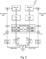
- FIG. 3 is a schematic view illustrating fluid flow through spray dispenser 10.
- pumps 14a and 14b pump fluids from reservoirs 12a and 12b, respectively, through heater module 46 to outlets 20a and 20b, respectively.
- Heater module 46 comprises A-side heater section 100a and B-side heater section 100b.
- A-side heater section 100a comprises primary heater 102a and boost heater 104a, and receives fluid from A-side pump 14a
- B-side heater section 100b comprises primary heater 102b and boost heater 104b, and receives fluid from B-side pump 14b.
- primary heater 102a and 102b and boost heaters 104a and 104b are shown as individual elements, each heater can in some embodiments be formed from multiple heating elements.
- A-side heater section 100a feeds outlet 20a, while B-side heater section 100b feeds outlet 20b.
- Each outlet connects to sprayer 27 via a corresponding outlet hose.
- Sprayer 27 can, for example, be a handheld sprayer applicator or spray gun that combines and sprays A-side and B-side fluids when a trigger is depressed.
- Return hoses connect sprayer 27 to return hose connections 22a and 22b, allowing unsprayed fluids to return to hose manifold 19.
- recirculation valves 21a and 21b enable fluid recirculation by providing a fluid path from sprayer 27 to reservoirs 12a and 12b via return hose connection 22a and 22b, recirculation hose connection 23a and 23b, recirculation hoses, and reservoir ports 24a and 24b.
- sprayer 27 is ordinarily closed (i.e. not spraying), and fluid can follow a closed circuit from reservoirs 12a or 12b through pumps 14a or 14b, outlet hose connections 20a or 20b, return hose connections 22a or 22b, recirculation hose connections 23a or 23b, and reservoir ports 24a or 24b back to reservoirs 12a or 12b.
- This valve state is primarily utilized in the recirculation mode, and circulates fluid through heaters in heater module 46 in order to increase the temperature of A- and B-side fluids so as to lower viscosities in preparation for spraying.
- pumps 14a and 14b operate at low pressures sufficient to circulate fluid, but not typically sufficient for spray application from sprayer 27.
- recirculation valves 21a and 21b prevent fluid flow from return hose connections 22a and 22b to recirculation hose connections 23a and 23b.
- This valve state is primarily utilized in the spray mode, such that fluid from reservoirs 12a and 12b and pumps 14a and 14b has no other flow path than through sprayer 27, and pressure at sprayer 27 is accordingly increased. This increased pressure allows fluids to be mixed, aerosolized, and sprayed. A-side and B-side fluids cure rapidly when in contact with one another (e.g. within ⁇ 10 seconds), and are accordingly only allowed to contact at sprayer 27.
- recirculation valves 21a may be only mostly closed in the spray mode, so as to alleviate overpressures at sprayer 27.
- Spray dispenser 10 powers boost heaters 104a and 104b in recirculation mode, thereby reducing warm-up times necessary to heat fluids to target operating temperatures before spraying can commence.
- pumps 14a and 14b operate at high pressures sufficient for spray application from sprayer 27.
- Motor 44 correspondingly draws relatively high power in the spray mode, and boost heaters 104a and 104b are accordingly deactivated.
- FIG. 4 is a logic flowchart illustrating method 200, a method of operation of spray applicator 10.
- mobile applicator 10 draws power from one or more grid connections to power controllers, sensors, and logic devices in primary controller 28, heater control system 48, and interface 30.
- Step S1 all power is drawn via interface 30 through two power circuits with separate grid connections: a heater power circuit, and a motor power circuit (see FIG. 6 , below).
- Primary controller 28 next enters a spray mode or a recirculation mode, as described above with respect to FIG. 4 .
- the mode may be selected directly by a user via interface 30.
- primary controller 28 may automatically enter the spray or recirculation mode based on sensed fluid pressure and/or temperature, commanded fluid pressure and/or temperature, elapsed time since startup, and/or power draw.
- primary controller 28 directs power to primary heaters 102a and 102b, to boost heaters 104a and 104b, and to motor 44.
- spray mode primary controller 28 directs power to primary heaters 102a and 102b and to motor 44.
- Step S4 Power routing is explained in greater detail below with respect to FIG. 6 .
- primary controller 28 and heater control system 48 may monitor the state of mobile applicator 10 and update its operating mode (i.e. spray or recirculation) based on new sensed or commanded values. (Step S5).
- FIG. 5 is a perspective view of heater module 46 and heater control system 48.
- FIG. 5 illustrates A-side heater section 100a, B-side heater section 100b, primary heaters 102a and 102b, boost heaters 104a and 104b, fire rod heaters 106 (with heating elements 108 and helical fluid lines 110), contactor 112, primary heater control modules 114a and 114b, auxiliary power relays 116a and 116b, boost relay 118, and heater logic controller 120.
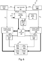
- FIG. 6 is a schematic view of primary controller 28, pump motor 44, heater module 46, and heater control system 48.
- FIGs. 5 and 6 illustrates primary heaters 102a and 102b, boost heaters 104a and 104b, contactor 112, primary heater control modules 114a and 114b, auxiliary power relays 116a and 116b, boost relay 118, heater logic controller 120, and temperature sensors 122a and 122b.
- FIGs. 5 and 6 are hereinafter discussed concurrently.
- A-side fluid from pump 14a flows first through boost heater 104a, and then through primary heater 102a of A-side heater section 100a.
- B-side fluid from pump 14b flows analogously through primary heater 102b and boost heater 104b of B-side heater section 100b.
- primary heaters 102a and 102b are connected to boost heaters 104a and 104b, respectively, via integral fluid passages within heater module 46.
- primary heaters 102a and 102b are connected to boost heaters 104a and 104b via external fluid lines, piping, or tubing.
- each heater (including primary heaters 102a and 102b, and boost heaters 104a and 104b) comprises at least one compact resistive heating element disposed to resistively heat passing fluid when pulsed with a nonzero voltage.
- each heater comprises a fire rod heater 106 with a heating element 108 and at least one wrapped fluid line 110.
- Heating elements 108 are thermally conductive rods formed, e.g., of aluminum or steel, and inset with resistive heaters.
- Helical fluid lines 110 are helical flow passages surrounding heating elements 108 and extending from one side to the other of primary heater 102a or 102b, or boost heater 104a or 104b.
- Helical fluid lines 110 can, for example, be fixed channels or flexible tubes coiled about heating elements 108. In alternative embodiments, other resistive heating elements can be substituted for fire rod heaters 106.
- Secondary heaters 104a and 104b may, for example, have approximately half the wattage of primary heaters 102a and 102b.
- primary heaters 102a and 102b may for example draw 1000W, and boost heaters 104a and 104b only 500W.
- primary heaters 102a and 102b may for example draw 1380W, and boost heaters 104a and 104b only 620W.
- Heater control system 48 delivers pulsed power to primary heaters 102a and 102b and boost heaters 104a and 104b at controlled intervals, in order to achieve and maintain target fluid temperatures while ensuring that overall power draw by spray dispenser 10 does not exceed available grid power.
- Grid power may, for example, be available at 120V or 230V via two 20A or 15A connections, respectively. In the depicted embodiment, grid power is drawn from two distinct grid connections with separate power circuits: heater power circuit H, and motor power circuit M. (see FIG. 6 ). In alternative embodiments, a larger or smaller number of grid connections and dedicated power circuits may be used. Power is routed through primary controller 28. Heater power circuit H powers primary heaters 102a and 102b.
- Motor power circuit M powers pump motor 44 during spray mode, and boost heaters 104a and 104b during recirculation mode.
- Pump motor 44 receives power via motor power circuit M directly from primary controller 28, while primary and boost heaters 102a, 102b, 104a, and 104b receive power indirectly via contactor 112.
- primary controller 28 acts as a motor controller for pump motor 44.
- Primary controller 28 can, for instance, control motor 44 to drive pumps 14a and 14b based on sensed or predicted pressure values to achieve target or commanded pressure values within spray dispenser 10, e.g. at sprayer 27.
- Primary controller simultaneously provides commanded temperatures CT a and CT b for A-side and B-side fluid, respectively.
- Commanded temperatures CT a and CT b are target temperatures that may be entered by a human operator, selected from a preset list, or determined by primary controller 28.
- Commanded temperatures CT a and CT b can be highly material-dependent, and are selected primarily to achieve desirable viscosities of A-side and B-side fluids. Commanded temperatures CT a and CT b need not be the same.
- Heater logic controller 120 processes commanded temperatures CT a and CT b to produce power commands PC a and PC b specifying power pulse intervals for primary heaters 102a and 102b, respectively.
- Heater logic controller 120 may in some embodiments base power commands PC a and PC b in part on differences between commanded temperatures CT a and CT b and actual fluid temperatures AT a and AT b provided by temperature sensors 122a and 122b, respectively (see FIG. 6 ).
- Temperature sensors 122a and 122b can, for example, be situated within fluid lines 16a and 16b, in heater module 46, and/or in reservoirs 12a and 12b. Power commands PC a and PC b are set to achieve and/or maintain target commanded temperatures CT a and CT b .
- Primary heater control modules 114a and 114b relay power received from heater power circuit H through contactor 112 to primary heaters 102a and 102b in discrete pulses specified by power commands PC a and PC b , respectively.
- Logic controller 120 commands more frequent pulses to achieve or maintain higher temperatures, or when differences between commanded temperatures CT a or CT b and actual fluid temperatures AT a and AT b are large.
- logic controller 120 commands less frequent pulses where commanded temperatures CT a or CT b are low, or where actual fluid temperatures are close to commanded values. Intervals of commanded pulses may range from multiple pulses each second to only few pulses per minute, or even several minutes between pulses.
- A- and B-side power commands PC a and PC b need not be the same.
- Auxiliary power relays 116a and 116b can, for instance, be solid state relays chained from primary heater control modules 114a and 114b, respectively.
- Boost relay 118 can, for instance, be an electromechanical relay.
- auxiliary power relays 116a and 116b draw pulsed power via contactor 112 based on A-side and B-side power commands PC a and PC b .
- auxiliary power relays 116a and 116b draw power from motor power circuit M.
- Auxiliary power relays 116a and 116b may, for instance, be chained off of heater control modules 114a and 114b and receive A- and B-side power commands PC a and PC b from heater control modules 114a and 114b, or may receive power commands PC a and PC b directly from logic controller 120.
- primary controller 28 commands boost relay 118 via boost command BC to relay power from motor power circuit M to contactor 112, so that boost heaters 104a and 104b receive power pulses whenever primary heaters 102a and 102b do.
- boost command BC instructs boost relay 118 to disconnect motor power circuit M from auxiliary power relays 116, interrupting power to boost heaters 104a and 104b.
- heater control system 48 ensures that boost heaters 104a and 104b draw power from motor power circuit M only during recirculation modes of spray dispenser 10, and not during spray modes.
- primary controller 28 may switch between spray and recirculation modes for provision of power to boost heaters 104a and 104b based on available amperage. For example, primary controller 28 may activate primary heaters 102a and 102b at all times, but activate boost heaters 104a and 104b (via boost command BC) only when a sensed power draw of motor 44 for pumps 14a and 14b drops below a threshold value. This threshold value is selected such that total power draw from motor 44 and heating module 46 never exceeds a rated circuit amperage limit (e.g. 15A or 20A each for motor power circuit M and heater power circuit H). In this way, spray and recirculation modes may be defined with respect to sensed power draw.
- a rated circuit amperage limit e.g. 15A or 20A each for motor power circuit M and heater power circuit H.
- primary controller 28 may switch between spray and recirculation modes for provision of power to boost heaters 104a and 104b based on commanded pressure or pressures for A-side and B-side fluids. For example, primary controller 28 may activate both primary heaters 102a and 102b at all times, but activate boost heaters 104a and 104b (via boost command BC) only when commanded fluid pressure falls below a threshold value. In this way, spray and recirculation modes may be defined with respect to commanded pressure values.
- Recirculation modes are low-pressure modes used to heat up A-side and B-side fluids to target temperatures prior to spraying.
- the heater control scheme utilized by heater control system 48 allows spray dispenser 10 to provide extra heating for A-side and B-side fluids during this heat-up period.
- spray modes are high-pressures modes used when spray dispenser 10 must pressurize fluids for spraying from sprayer 27.
- the heater control scheme described above allows spray dispenser to conserve power for motor 44 of pumps 14a and 14b during spray modes by deactivating boost heaters 104a and 104b to reduce heating system power draw.
- Spray and recirculation modes are delineated such that heater control system 48 ensures total power draw of spray dispenser 10 will not exceed a maximum current limit.
Landscapes
- Engineering & Computer Science (AREA)
- Mechanical Engineering (AREA)
- Nozzles (AREA)
- Control Of Resistance Heating (AREA)
- Resistance Heating (AREA)
Claims (15)
- Mobile Sprühauftragsvorrichtung (10), die Folgendes umfasst:ein Fluidzirkulationssystem mit einer motorgetriebenen Pumpe (14a; 14b), die dafür geeignet ist, Fluid aus einem Fluidreservoir (12a; 12b) in einem Hochdrucksprühmodus und einem Niederdruck-Rezirkulationsmodus zu zirkulieren, und das Fluid einer Sprühdüse (27) zuzuführen, wobei die motorgetriebene Pumpe dafür konfiguriert ist, im Niederdruck-Rezirkulationsmodus weniger Leistung zu verbrauchen als im Hochdrucksprühmodus;eine Heizeinheit (100a; 100b), die innerhalb des Fluidzirkulationssystems angeordnet ist, um das Fluid auf eine Solltemperatur zu erwärmen, wobei die Heizeinheit Folgendes umfasst:eine primäre Heizvorrichtung (102a; 102b), die dafür konfiguriert ist, sowohl während des Hochdrucksprühmodus als auch des Niederdruck-Rezirkulationsmodus aktiv zu sein; undeine Zusatzheizvorrichtung (104a; 104b), die mit der primären Heizvorrichtung in Strömungsverbindung steht und dafür konfiguriert ist, nur während des Niederdruck-Rezirkulationsmodus aktiv zu sein.
- Mobile Sprühauftragsvorrichtung nach Anspruch 1, wobei die primäre Heizvorrichtung und die Zusatzheizvorrichtung Widerstandsheizvorrichtungen sind.
- Mobile Sprühauftragsvorrichtung nach Anspruch 2, wobei die primäre Heizvorrichtung und die Zusatzheizvorrichtung Firerod-Heizpatronen sind, die einen schraubenförmigen Fluidpfad um ein zylindrisches Widerstandselement herum umfassen, und/oder wobei die primäre Heizvorrichtung und die Zusatzheizvorrichtung dafür konfiguriert sind, Energie von einem gemeinsam genutzten elektrischen Schaltschütz zu beziehen.
- Mobile Sprühauftragsvorrichtung nach Anspruch 2 oder 3, die des Weiteren ein Primärheizvorrichtungs-Steuerungsmodul (114a; 114b) und ein Logiksteuerungsmodul (120) umfasst, wobei das Primärheizvorrichtungs-Steuerungsmodul dafür konfiguriert ist, Strom zu der primären Heizvorrichtung gemäß einem Steuerungssignal von dem Logiksteuerungsmodul zu regeln, das ein Stromimpulsintervall so einstellt, dass die Solltemperatur erreicht und aufrecht erhalten wird.
- Mobile Sprühauftragsvorrichtung nach Anspruch 4, wobei ein mit dem Primärheizvorrichtungs-Steuerungsmodul verknüpftes Festkörper-Hilfsrelais (116a; 116b) dafür konfiguriert ist, den Strom zu der Zusatzheizvorrichtung so zu regeln, dass die Zusatzheizvorrichtung Stromimpulse nur dann empfängt, wenn die primäre Heizvorrichtung Stromimpulse empfängt.
- Mobile Sprühauftragsvorrichtung nach einem der vorangehenden Ansprüche, die des Weiteren eine primäre Steuereinheit (28) umfasst, die dafür konfiguriert ist, die der motorgetriebenen Pumpe zugeführte Leistung so zu steuern, dass die motorgetriebene Pumpe im Hochdrucksprühmodus mehr Strom verbraucht als im Niederdruck-Rezirkulationsmodus.
- Mobile Sprühauftragsvorrichtung nach Anspruch 6, wobei die primäre Steuereinheit dafür konfiguriert ist, die der motorgetriebenen Pumpe zugeführte Leistung so zu steuern, dass ein Soll-Fluiddruck erreicht wird.
- Mobile Sprühauftragsvorrichtung nach Anspruch 6 oder 7, die des Weiteren ein elektromechanisches Relais (118) umfasst, das dafür konfiguriert ist, auf der Basis eines Niederspannungssignals der Motorsteuereinheit die Zusatzheizvorrichtung im Niederdruck-Rezirkulationsmodus zu aktivieren und die Zusatzheizvorrichtung im Hochdrucksprühmodus zu deaktivieren.
- Mobile Sprühauftragsvorrichtung nach Anspruch 8, wobei eine Abgrenzung zwischen dem Niederdruck-Rezirkulationsmodus und dem Hochdrucksprühmodus sicherstellt, dass die Gesamtleistungsaufnahme der motorgetriebenen Pumpe und der Heizeinheit eine maximale Stromobergrenze nicht überschreitet.
- Mobile Sprühauftragsvorrichtung nach Anspruch 9, wobei die primäre Heizvorrichtung dafür konfiguriert ist, Leistung über einen erster Leistungsstromkreis zu empfangen, und die motorgetriebene Pumpe und die Zusatzheizvorrichtung dafür konfiguriert sind, Leistung über einen zweiten Leistungsstromkreis zu beziehen, und wobei der erste Leistungsstromkreis und der zweite Leistungsstromkreis separate maximalen Stromobergrenzen haben.
- Mobile Sprühauftragsvorrichtung nach einem der vorangehenden Ansprüche, wobei das Fluidzirkulationssystem separate motorgetriebene Pumpen, Fluidreservoire und Fluidleitungen für zwei voneinander getrennte Fluide enthält, die in der Sprühdüse vermischt werden, und die Heizeinheit separate Primär- und Zusatzheizvorrichtungen für jedes Fluid umfasst; und wobei bevorzugt die separaten Primär- und Zusatzheizvorrichtungen für jedes Fluid dafür konfiguriert sind, separat gesteuert zu werden, um verschiedene Solltemperaturen zu erreichen.
- Mobile Sprühauftragsvorrichtung nach Anspruch 1, die des Weiteren Folgendes umfasst:ein Steuerungssystem, das dafür ausgelegt ist, sowohl die primäre Heizvorrichtung als auch die Zusatzheizvorrichtung zu aktivieren, wenn die motorgetriebene Pumpe weniger Leistung verbraucht als ein Schwellenwert, und dafür ausgelegt ist, anderenfalls nur die primäre Heizvorrichtung zu aktivieren.
- Mobile Sprühauftragsvorrichtung nach Anspruch 12, wobei der Schwellenwert so gewählt wird, dass die Gesamtleistungsaufnahme der motorgetriebenen Pumpe, der primären Heizvorrichtung und der Zusatzheizvorrichtung niemals eine Netzstromleistung übersteigt; und/oder wobei die Zusatzheizvorrichtung im Wesentlichen die Hälfte der Wattleistung der primären Heizvorrichtung aufnimmt.
- Heizvorrichtungs-Steuerungsverfahren für eine mobile Sprühauftragsvorrichtung (10) mit einer motorgetriebenen Pumpe (14a; 14b), einer primären Heizvorrichtung (102a; 102b) und einer Zusatzheizvorrichtung (104a; 104b), wobei das Verfahren Folgendes umfasst:Beaufschlagen der motorgetriebenen Pumpe mit Energie, um Fluid mit einem erforderlichen Druck zu zirkulieren;Pulsieren von Leistung zu der primären Heizvorrichtung in regelmäßigen Intervallen, die so gewählt sind, dass das zirkulierende Fluid auf eine Solltemperatur erwärmt wird;Pulsieren von Leistung zu der Zusatzheizvorrichtung synchron mit der primären Heizvorrichtung, während die motorgetriebenen Pumpe in einem Niederdruck-Rezirkulationsmodus arbeitet; undAbschalten der Leistung zu der Zusatzheizvorrichtung, während die motorgetriebene Pumpe in einem Hochdrucksprühmodus arbeitet.
- Heizvorrichtungs-Steuerungsverfahren nach Anspruch 14, wobei entweder a) das Heizvorrichtungs-Steuerungsverfahren des Weiteren umfasst, die Leistungsaufnahme der motorgetriebenen Pumpe zu bestimmen und die Leistungsaufnahme der motorgetriebenen Pumpe mit einer Schwelle Leistungsaufnahme zu vergleichen, und wobei der Niederdruck-Rezirkulationsmodus dadurch definiert ist, dass die Leistungsaufnahme der motorgetriebenen Pumpe unter den Schwellenleistungswert fällt, während der Hochdrucksprühmodus dadurch definiert ist, dass die Leistungsaufnahme der motorgetriebenen Pumpe den Schwellenleistungswert übersteigt; oder b) das Heizvorrichtungs-Steuerungsverfahren des Weiteren umfasst, die Leistung zu der motorgetriebenen Pumpe auf der Basis eines befohlenen Wertes des erforderlichen Drucks zu steuern und den befohlenen Wert mit einem Schwellendruckwert zu vergleichen, und wobei der Niederdruck-Rezirkulationsmodus dadurch definiert ist, dass der befohlene Wert unter den Schwellendruckwert fällt, während der Hochdrucksprühmodus dadurch definiert ist, dass der befohlene Wert den Schwellendruckwert übersteigt.
Priority Applications (1)
| Application Number | Priority Date | Filing Date | Title |
|---|---|---|---|
| PL13866372T PL2931437T3 (pl) | 2012-12-17 | 2013-12-16 | Podwójny układ grzejnikowy do dozownika natryskowego |
Applications Claiming Priority (2)
| Application Number | Priority Date | Filing Date | Title |
|---|---|---|---|
| US201261737883P | 2012-12-17 | 2012-12-17 | |
| PCT/US2013/075414 WO2014099796A1 (en) | 2012-12-17 | 2013-12-16 | Dual heater system for spray dispenser |
Publications (3)
| Publication Number | Publication Date |
|---|---|
| EP2931437A1 EP2931437A1 (de) | 2015-10-21 |
| EP2931437A4 EP2931437A4 (de) | 2016-07-27 |
| EP2931437B1 true EP2931437B1 (de) | 2017-11-22 |
Family
ID=50979085
Family Applications (1)
| Application Number | Title | Priority Date | Filing Date |
|---|---|---|---|
| EP13866372.9A Active EP2931437B1 (de) | 2012-12-17 | 2013-12-16 | System mit zwei erhitzern für eine sprühdose |
Country Status (9)
| Country | Link |
|---|---|
| US (1) | US9849475B2 (de) |
| EP (1) | EP2931437B1 (de) |
| JP (1) | JP6262766B2 (de) |
| KR (1) | KR102145377B1 (de) |
| CN (1) | CN104870099B (de) |
| ES (1) | ES2656162T3 (de) |
| PL (1) | PL2931437T3 (de) |
| RU (1) | RU2645491C2 (de) |
| WO (1) | WO2014099796A1 (de) |
Families Citing this family (21)
| Publication number | Priority date | Publication date | Assignee | Title |
|---|---|---|---|---|
| US11815919B2 (en) | 2013-02-11 | 2023-11-14 | Graco Minnesota Inc. | Operator interface device and distributed control for fluid dispensing systems |
| US11184689B2 (en) * | 2013-02-11 | 2021-11-23 | Graco Minnesota Inc. | Remote monitoring for fluid applicator system |
| US10969805B2 (en) | 2013-02-11 | 2021-04-06 | Graco Minnesota Inc. | Paint sprayer distributed control and output volume monitoring architectures |
| US11750954B2 (en) * | 2013-02-11 | 2023-09-05 | Graco Minnesota Inc. | Remote monitoring for fluid applicator system |
| EP2954504A4 (de) * | 2013-02-11 | 2016-10-12 | Graco Minnesota Inc | Fernüberwachung für ein fluidapplikatorsystem |
| GB201313536D0 (en) * | 2013-07-30 | 2013-09-11 | Digital Line Markers Fze | Line marking apparatus having a closed circulation system |
| DE102014014971B4 (de) * | 2014-10-14 | 2022-10-13 | Scheppach Gmbh | Handspritze |
| US9895708B2 (en) | 2014-10-20 | 2018-02-20 | Akurate Dynamics LLC | System for dispensing multiple component chemical sprays |
| EP4234098B1 (de) * | 2016-01-12 | 2024-10-16 | Graco Minnesota Inc. | Integrierter pumpenschutz und steuerungsverriegelung |
| EP3429758A4 (de) * | 2016-03-17 | 2019-04-03 | Akurate Dynamics LLC | System zur ausgabe von mehrkomponentigen chemischen sprays |
| US10315236B2 (en) * | 2016-10-25 | 2019-06-11 | Cornelius, Inc. | Systems and methods of food dispenser cleaning |
| DE102016224296A1 (de) * | 2016-12-06 | 2018-06-07 | Eberspächer Catem Gmbh & Co. Kg | Elektrische heizvorrichtung |
| US10926300B2 (en) * | 2017-12-28 | 2021-02-23 | Harvey William McCracken | Watercraft cleaning systems and methods |
| CA3099456A1 (en) | 2017-12-29 | 2019-07-04 | At Group, Llc | Apparatus for dispensing a mixture of at least two liquid components |
| EP4524090A3 (de) * | 2018-05-09 | 2025-06-18 | Wayne Fueling Systems LLC | Flüssigkeitsabgabeeinheit mit abtausystem |
| WO2020216681A1 (en) * | 2019-04-25 | 2020-10-29 | Covestro Intellectual Property Gmbh & Co. Kg | Mobile containment and mixing plant, and related method |
| USD953480S1 (en) * | 2019-09-05 | 2022-05-31 | Hyung Goo KIM | Portable polyurethane foam dispenser |
| JP7488345B2 (ja) * | 2020-02-12 | 2024-05-21 | カーライル フルイド テクノロジーズ,リミティド ライアビリティ カンパニー | 流体加熱制御のためのシステム及び方法 |
| GR20200100737A (el) * | 2020-12-17 | 2022-07-07 | Λεωνιδας Νικολαου Παπαδακης | Aytonomo mhxanhma εφαρμογης δυο συστατικων |
| US12402577B2 (en) * | 2021-03-31 | 2025-09-02 | Komatsu America Corp. | Power control system |
| US12122068B2 (en) * | 2021-05-03 | 2024-10-22 | Graco Minnesota Inc. | System and method to auto-pressurize prior to dispense in a circulation dispense system |
Family Cites Families (16)
| Publication number | Priority date | Publication date | Assignee | Title |
|---|---|---|---|---|
| US4809909A (en) * | 1985-06-13 | 1989-03-07 | Glas-Craft, Inc. | Plural component application system |
| US5171613A (en) * | 1990-09-21 | 1992-12-15 | Union Carbide Chemicals & Plastics Technology Corporation | Apparatus and methods for application of coatings with supercritical fluids as diluents by spraying from an orifice |
| US5662269A (en) * | 1995-09-15 | 1997-09-02 | Francis; Dale | Pressure washer with heat exchanger |
| JP3409200B2 (ja) * | 1996-12-26 | 2003-05-26 | 株式会社守谷フィールド | 発泡材の生成方法 |
| GB9727366D0 (en) | 1997-12-24 | 1998-02-25 | Unilever Plc | Sprayhead |
| AU2216899A (en) * | 1998-01-23 | 1999-08-09 | Mark Rite Lines Of Montana, Inc. | Plural component striping spray system and method |
| JPH11267085A (ja) * | 1998-03-23 | 1999-10-05 | Matsushita Electric Ind Co Ltd | 食器洗浄機 |
| US6161775A (en) * | 1999-02-23 | 2000-12-19 | E. D. Etnyre & Co. | Feedline assembly and asphalt circulation system for an asphalt distributor |
| US6581220B2 (en) | 2001-04-30 | 2003-06-24 | David Yekutiely | Method and appratus for aromatherapy shower |
| US7641131B2 (en) * | 2002-10-02 | 2010-01-05 | Sbr Investments Company Llc | Vehicle windshield cleaning system |
| BRPI0411934A (pt) * | 2003-06-27 | 2006-08-29 | Recticel | método para produzir um artigo compreendendo pelo menos um camada de poliuretano |
| KR100515608B1 (ko) * | 2003-12-24 | 2005-09-16 | 재단법인 포항산업과학연구원 | 분말 예열 장치가 구비된 저온 스프레이 장치 |
| US20070045289A1 (en) * | 2005-08-02 | 2007-03-01 | John Kott | Portable spray system |
| CN102009012B (zh) * | 2010-03-31 | 2012-10-24 | 范维林 | 带温度控制的液态雾化气溶胶发生装置 |
| CN202045035U (zh) * | 2011-03-23 | 2011-11-23 | 烟台市芝罘振兴聚氨酯材料厂 | 双组分高压喷涂机 |
| WO2012174380A2 (en) * | 2011-06-16 | 2012-12-20 | Graco Minnesota Inc. | Waste heat recovery system for pumping system |
-
2013
- 2013-12-16 EP EP13866372.9A patent/EP2931437B1/de active Active
- 2013-12-16 JP JP2015548044A patent/JP6262766B2/ja active Active
- 2013-12-16 WO PCT/US2013/075414 patent/WO2014099796A1/en not_active Ceased
- 2013-12-16 US US14/650,758 patent/US9849475B2/en active Active
- 2013-12-16 PL PL13866372T patent/PL2931437T3/pl unknown
- 2013-12-16 KR KR1020157018826A patent/KR102145377B1/ko active Active
- 2013-12-16 CN CN201380065819.XA patent/CN104870099B/zh active Active
- 2013-12-16 ES ES13866372.9T patent/ES2656162T3/es active Active
- 2013-12-16 RU RU2015127916A patent/RU2645491C2/ru active
Non-Patent Citations (1)
| Title |
|---|
| None * |
Also Published As
| Publication number | Publication date |
|---|---|
| WO2014099796A1 (en) | 2014-06-26 |
| US20160184846A1 (en) | 2016-06-30 |
| KR20150097631A (ko) | 2015-08-26 |
| EP2931437A1 (de) | 2015-10-21 |
| KR102145377B1 (ko) | 2020-08-18 |
| JP6262766B2 (ja) | 2018-01-17 |
| RU2645491C2 (ru) | 2018-02-21 |
| PL2931437T3 (pl) | 2018-04-30 |
| JP2016503722A (ja) | 2016-02-08 |
| CN104870099B (zh) | 2017-02-15 |
| US9849475B2 (en) | 2017-12-26 |
| EP2931437A4 (de) | 2016-07-27 |
| CN104870099A (zh) | 2015-08-26 |
| ES2656162T3 (es) | 2018-02-23 |
| RU2015127916A (ru) | 2017-01-25 |
Similar Documents
| Publication | Publication Date | Title |
|---|---|---|
| EP2931437B1 (de) | System mit zwei erhitzern für eine sprühdose | |
| US8784390B2 (en) | Skin treatment spray nozzle system for automatic spray gantry | |
| US8486030B2 (en) | Hand held skin treatment spray system with proportional air and liquid control | |
| US20110133001A1 (en) | Hand held skin treatment spray system | |
| CA2552160C (en) | Cooling system for the cooling of heat-producing devices in an aircraft | |
| EP2708288A2 (de) | Präzisonspumpsystem für Spritzbehandlungszyklen | |
| EP2699122A2 (de) | Tragbare hautbehandlungssprühvorrichtung und system damit | |
| JP2016163883A (ja) | 可変出力吐出アプリケーター及び関連する吐出方法 | |
| WO2013070700A1 (en) | Cooling system and method | |
| JP2016163884A (ja) | 出力可変吐出アプリケーター用液体分流モジュール及び関連方法 | |
| US20180056311A1 (en) | Heated spray system | |
| KR20160034954A (ko) | 분무 시스템 압력 및 비율 제어 | |
| JP2022501185A (ja) | 投与材料冷却装置を備える投与システム | |
| JPH07171465A (ja) | 連続式溶融接着剤塗布器 | |
| JP4486502B2 (ja) | 噴霧装置に即した方法および噴霧装置 | |
| KR20160033166A (ko) | 분무 시스템을 위한 비례 실린더 | |
| US9814096B2 (en) | Power management for hot melt dispensing systems | |
| KR102429008B1 (ko) | 실러 순환 시스템 | |
| US20140119715A1 (en) | Heater power control system | |
| KR101181562B1 (ko) | 사출금형용 온도조절기의 온도조절장치 및 사출금형용 온도조절기 |
Legal Events
| Date | Code | Title | Description |
|---|---|---|---|
| PUAI | Public reference made under article 153(3) epc to a published international application that has entered the european phase |
Free format text: ORIGINAL CODE: 0009012 |
|
| 17P | Request for examination filed |
Effective date: 20150717 |
|
| AK | Designated contracting states |
Kind code of ref document: A1 Designated state(s): AL AT BE BG CH CY CZ DE DK EE ES FI FR GB GR HR HU IE IS IT LI LT LU LV MC MK MT NL NO PL PT RO RS SE SI SK SM TR |
|
| AX | Request for extension of the european patent |
Extension state: BA ME |
|
| DAX | Request for extension of the european patent (deleted) | ||
| A4 | Supplementary search report drawn up and despatched |
Effective date: 20160629 |
|
| RIC1 | Information provided on ipc code assigned before grant |
Ipc: B05B 9/06 20060101AFI20160623BHEP Ipc: B05B 7/04 20060101ALI20160623BHEP Ipc: B05B 1/24 20060101ALI20160623BHEP |
|
| RIC1 | Information provided on ipc code assigned before grant |
Ipc: B05B 9/06 20060101AFI20170517BHEP Ipc: B05B 1/24 20060101ALI20170517BHEP Ipc: B05B 7/04 20060101ALI20170517BHEP |
|
| GRAP | Despatch of communication of intention to grant a patent |
Free format text: ORIGINAL CODE: EPIDOSNIGR1 |
|
| STAA | Information on the status of an ep patent application or granted ep patent |
Free format text: STATUS: GRANT OF PATENT IS INTENDED |
|
| INTG | Intention to grant announced |
Effective date: 20170627 |
|
| GRAS | Grant fee paid |
Free format text: ORIGINAL CODE: EPIDOSNIGR3 |
|
| GRAA | (expected) grant |
Free format text: ORIGINAL CODE: 0009210 |
|
| STAA | Information on the status of an ep patent application or granted ep patent |
Free format text: STATUS: THE PATENT HAS BEEN GRANTED |
|
| AK | Designated contracting states |
Kind code of ref document: B1 Designated state(s): AL AT BE BG CH CY CZ DE DK EE ES FI FR GB GR HR HU IE IS IT LI LT LU LV MC MK MT NL NO PL PT RO RS SE SI SK SM TR |
|
| REG | Reference to a national code |
Ref country code: GB Ref legal event code: FG4D |
|
| REG | Reference to a national code |
Ref country code: CH Ref legal event code: EP |
|
| REG | Reference to a national code |
Ref country code: IE Ref legal event code: FG4D |
|
| REG | Reference to a national code |
Ref country code: AT Ref legal event code: REF Ref document number: 947916 Country of ref document: AT Kind code of ref document: T Effective date: 20171215 |
|
| REG | Reference to a national code |
Ref country code: DE Ref legal event code: R096 Ref document number: 602013029962 Country of ref document: DE |
|
| REG | Reference to a national code |
Ref country code: ES Ref legal event code: FG2A Ref document number: 2656162 Country of ref document: ES Kind code of ref document: T3 Effective date: 20180223 |
|
| REG | Reference to a national code |
Ref country code: NL Ref legal event code: MP Effective date: 20171122 |
|
| REG | Reference to a national code |
Ref country code: LT Ref legal event code: MG4D |
|
| REG | Reference to a national code |
Ref country code: AT Ref legal event code: MK05 Ref document number: 947916 Country of ref document: AT Kind code of ref document: T Effective date: 20171122 |
|
| PG25 | Lapsed in a contracting state [announced via postgrant information from national office to epo] |
Ref country code: FI Free format text: LAPSE BECAUSE OF FAILURE TO SUBMIT A TRANSLATION OF THE DESCRIPTION OR TO PAY THE FEE WITHIN THE PRESCRIBED TIME-LIMIT Effective date: 20171122 Ref country code: SE Free format text: LAPSE BECAUSE OF FAILURE TO SUBMIT A TRANSLATION OF THE DESCRIPTION OR TO PAY THE FEE WITHIN THE PRESCRIBED TIME-LIMIT Effective date: 20171122 Ref country code: NO Free format text: LAPSE BECAUSE OF FAILURE TO SUBMIT A TRANSLATION OF THE DESCRIPTION OR TO PAY THE FEE WITHIN THE PRESCRIBED TIME-LIMIT Effective date: 20180222 Ref country code: LT Free format text: LAPSE BECAUSE OF FAILURE TO SUBMIT A TRANSLATION OF THE DESCRIPTION OR TO PAY THE FEE WITHIN THE PRESCRIBED TIME-LIMIT Effective date: 20171122 Ref country code: NL Free format text: LAPSE BECAUSE OF FAILURE TO SUBMIT A TRANSLATION OF THE DESCRIPTION OR TO PAY THE FEE WITHIN THE PRESCRIBED TIME-LIMIT Effective date: 20171122 |
|
| PG25 | Lapsed in a contracting state [announced via postgrant information from national office to epo] |
Ref country code: GR Free format text: LAPSE BECAUSE OF FAILURE TO SUBMIT A TRANSLATION OF THE DESCRIPTION OR TO PAY THE FEE WITHIN THE PRESCRIBED TIME-LIMIT Effective date: 20180223 Ref country code: RS Free format text: LAPSE BECAUSE OF FAILURE TO SUBMIT A TRANSLATION OF THE DESCRIPTION OR TO PAY THE FEE WITHIN THE PRESCRIBED TIME-LIMIT Effective date: 20171122 Ref country code: AT Free format text: LAPSE BECAUSE OF FAILURE TO SUBMIT A TRANSLATION OF THE DESCRIPTION OR TO PAY THE FEE WITHIN THE PRESCRIBED TIME-LIMIT Effective date: 20171122 Ref country code: LV Free format text: LAPSE BECAUSE OF FAILURE TO SUBMIT A TRANSLATION OF THE DESCRIPTION OR TO PAY THE FEE WITHIN THE PRESCRIBED TIME-LIMIT Effective date: 20171122 Ref country code: BG Free format text: LAPSE BECAUSE OF FAILURE TO SUBMIT A TRANSLATION OF THE DESCRIPTION OR TO PAY THE FEE WITHIN THE PRESCRIBED TIME-LIMIT Effective date: 20180222 Ref country code: HR Free format text: LAPSE BECAUSE OF FAILURE TO SUBMIT A TRANSLATION OF THE DESCRIPTION OR TO PAY THE FEE WITHIN THE PRESCRIBED TIME-LIMIT Effective date: 20171122 |
|
| PG25 | Lapsed in a contracting state [announced via postgrant information from national office to epo] |
Ref country code: SK Free format text: LAPSE BECAUSE OF FAILURE TO SUBMIT A TRANSLATION OF THE DESCRIPTION OR TO PAY THE FEE WITHIN THE PRESCRIBED TIME-LIMIT Effective date: 20171122 Ref country code: CZ Free format text: LAPSE BECAUSE OF FAILURE TO SUBMIT A TRANSLATION OF THE DESCRIPTION OR TO PAY THE FEE WITHIN THE PRESCRIBED TIME-LIMIT Effective date: 20171122 Ref country code: DK Free format text: LAPSE BECAUSE OF FAILURE TO SUBMIT A TRANSLATION OF THE DESCRIPTION OR TO PAY THE FEE WITHIN THE PRESCRIBED TIME-LIMIT Effective date: 20171122 Ref country code: EE Free format text: LAPSE BECAUSE OF FAILURE TO SUBMIT A TRANSLATION OF THE DESCRIPTION OR TO PAY THE FEE WITHIN THE PRESCRIBED TIME-LIMIT Effective date: 20171122 Ref country code: CY Free format text: LAPSE BECAUSE OF FAILURE TO SUBMIT A TRANSLATION OF THE DESCRIPTION OR TO PAY THE FEE WITHIN THE PRESCRIBED TIME-LIMIT Effective date: 20171122 |
|
| REG | Reference to a national code |
Ref country code: CH Ref legal event code: PL |
|
| REG | Reference to a national code |
Ref country code: DE Ref legal event code: R097 Ref document number: 602013029962 Country of ref document: DE |
|
| PG25 | Lapsed in a contracting state [announced via postgrant information from national office to epo] |
Ref country code: SM Free format text: LAPSE BECAUSE OF FAILURE TO SUBMIT A TRANSLATION OF THE DESCRIPTION OR TO PAY THE FEE WITHIN THE PRESCRIBED TIME-LIMIT Effective date: 20171122 Ref country code: IT Free format text: LAPSE BECAUSE OF FAILURE TO SUBMIT A TRANSLATION OF THE DESCRIPTION OR TO PAY THE FEE WITHIN THE PRESCRIBED TIME-LIMIT Effective date: 20171122 Ref country code: RO Free format text: LAPSE BECAUSE OF FAILURE TO SUBMIT A TRANSLATION OF THE DESCRIPTION OR TO PAY THE FEE WITHIN THE PRESCRIBED TIME-LIMIT Effective date: 20171122 |
|
| REG | Reference to a national code |
Ref country code: IE Ref legal event code: MM4A |
|
| PG25 | Lapsed in a contracting state [announced via postgrant information from national office to epo] |
Ref country code: LU Free format text: LAPSE BECAUSE OF NON-PAYMENT OF DUE FEES Effective date: 20171216 Ref country code: MT Free format text: LAPSE BECAUSE OF NON-PAYMENT OF DUE FEES Effective date: 20171216 |
|
| PLBE | No opposition filed within time limit |
Free format text: ORIGINAL CODE: 0009261 |
|
| REG | Reference to a national code |
Ref country code: FR Ref legal event code: ST Effective date: 20180831 |
|
| STAA | Information on the status of an ep patent application or granted ep patent |
Free format text: STATUS: NO OPPOSITION FILED WITHIN TIME LIMIT |
|
| REG | Reference to a national code |
Ref country code: BE Ref legal event code: MM Effective date: 20171231 |
|
| GBPC | Gb: european patent ceased through non-payment of renewal fee |
Effective date: 20180222 |
|
| 26N | No opposition filed |
Effective date: 20180823 |
|
| PG25 | Lapsed in a contracting state [announced via postgrant information from national office to epo] |
Ref country code: IE Free format text: LAPSE BECAUSE OF NON-PAYMENT OF DUE FEES Effective date: 20171216 Ref country code: FR Free format text: LAPSE BECAUSE OF NON-PAYMENT OF DUE FEES Effective date: 20180122 |
|
| PG25 | Lapsed in a contracting state [announced via postgrant information from national office to epo] |
Ref country code: BE Free format text: LAPSE BECAUSE OF NON-PAYMENT OF DUE FEES Effective date: 20171231 Ref country code: SI Free format text: LAPSE BECAUSE OF FAILURE TO SUBMIT A TRANSLATION OF THE DESCRIPTION OR TO PAY THE FEE WITHIN THE PRESCRIBED TIME-LIMIT Effective date: 20171122 Ref country code: LI Free format text: LAPSE BECAUSE OF NON-PAYMENT OF DUE FEES Effective date: 20171231 Ref country code: CH Free format text: LAPSE BECAUSE OF NON-PAYMENT OF DUE FEES Effective date: 20171231 |
|
| PG25 | Lapsed in a contracting state [announced via postgrant information from national office to epo] |
Ref country code: GB Free format text: LAPSE BECAUSE OF NON-PAYMENT OF DUE FEES Effective date: 20180222 |
|
| PG25 | Lapsed in a contracting state [announced via postgrant information from national office to epo] |
Ref country code: HU Free format text: LAPSE BECAUSE OF FAILURE TO SUBMIT A TRANSLATION OF THE DESCRIPTION OR TO PAY THE FEE WITHIN THE PRESCRIBED TIME-LIMIT; INVALID AB INITIO Effective date: 20131216 Ref country code: MC Free format text: LAPSE BECAUSE OF FAILURE TO SUBMIT A TRANSLATION OF THE DESCRIPTION OR TO PAY THE FEE WITHIN THE PRESCRIBED TIME-LIMIT Effective date: 20171122 |
|
| PG25 | Lapsed in a contracting state [announced via postgrant information from national office to epo] |
Ref country code: MK Free format text: LAPSE BECAUSE OF FAILURE TO SUBMIT A TRANSLATION OF THE DESCRIPTION OR TO PAY THE FEE WITHIN THE PRESCRIBED TIME-LIMIT Effective date: 20171122 |
|
| PG25 | Lapsed in a contracting state [announced via postgrant information from national office to epo] |
Ref country code: TR Free format text: LAPSE BECAUSE OF FAILURE TO SUBMIT A TRANSLATION OF THE DESCRIPTION OR TO PAY THE FEE WITHIN THE PRESCRIBED TIME-LIMIT Effective date: 20171122 |
|
| PG25 | Lapsed in a contracting state [announced via postgrant information from national office to epo] |
Ref country code: PT Free format text: LAPSE BECAUSE OF FAILURE TO SUBMIT A TRANSLATION OF THE DESCRIPTION OR TO PAY THE FEE WITHIN THE PRESCRIBED TIME-LIMIT Effective date: 20171122 |
|
| PG25 | Lapsed in a contracting state [announced via postgrant information from national office to epo] |
Ref country code: AL Free format text: LAPSE BECAUSE OF FAILURE TO SUBMIT A TRANSLATION OF THE DESCRIPTION OR TO PAY THE FEE WITHIN THE PRESCRIBED TIME-LIMIT Effective date: 20171122 Ref country code: IS Free format text: LAPSE BECAUSE OF FAILURE TO SUBMIT A TRANSLATION OF THE DESCRIPTION OR TO PAY THE FEE WITHIN THE PRESCRIBED TIME-LIMIT Effective date: 20180322 |
|
| PGFP | Annual fee paid to national office [announced via postgrant information from national office to epo] |
Ref country code: ES Payment date: 20230102 Year of fee payment: 10 |
|
| P01 | Opt-out of the competence of the unified patent court (upc) registered |
Effective date: 20230531 |
|
| PGFP | Annual fee paid to national office [announced via postgrant information from national office to epo] |
Ref country code: PL Payment date: 20241210 Year of fee payment: 12 |
|
| REG | Reference to a national code |
Ref country code: ES Ref legal event code: FD2A Effective date: 20250131 |
|
| PGFP | Annual fee paid to national office [announced via postgrant information from national office to epo] |
Ref country code: DE Payment date: 20241227 Year of fee payment: 12 |
|
| PG25 | Lapsed in a contracting state [announced via postgrant information from national office to epo] |
Ref country code: ES Free format text: LAPSE BECAUSE OF NON-PAYMENT OF DUE FEES Effective date: 20231217 |