EP2930765A1 - Batteriepackvorrichtung, verfahren zur überprüfung der batteriepackvorrichtung und computerlesbares medium - Google Patents
Batteriepackvorrichtung, verfahren zur überprüfung der batteriepackvorrichtung und computerlesbares medium Download PDFInfo
- Publication number
- EP2930765A1 EP2930765A1 EP13860913.6A EP13860913A EP2930765A1 EP 2930765 A1 EP2930765 A1 EP 2930765A1 EP 13860913 A EP13860913 A EP 13860913A EP 2930765 A1 EP2930765 A1 EP 2930765A1
- Authority
- EP
- European Patent Office
- Prior art keywords
- cell
- battery module
- battery
- cells
- battery modules
- Prior art date
- Legal status (The legal status is an assumption and is not a legal conclusion. Google has not performed a legal analysis and makes no representation as to the accuracy of the status listed.)
- Withdrawn
Links
Images


Classifications
-
- B—PERFORMING OPERATIONS; TRANSPORTING
- B60—VEHICLES IN GENERAL
- B60L—PROPULSION OF ELECTRICALLY-PROPELLED VEHICLES; SUPPLYING ELECTRIC POWER FOR AUXILIARY EQUIPMENT OF ELECTRICALLY-PROPELLED VEHICLES; ELECTRODYNAMIC BRAKE SYSTEMS FOR VEHICLES IN GENERAL; MAGNETIC SUSPENSION OR LEVITATION FOR VEHICLES; MONITORING OPERATING VARIABLES OF ELECTRICALLY-PROPELLED VEHICLES; ELECTRIC SAFETY DEVICES FOR ELECTRICALLY-PROPELLED VEHICLES
- B60L3/00—Electric devices on electrically-propelled vehicles for safety purposes; Monitoring operating variables, e.g. speed, deceleration or energy consumption
- B60L3/0023—Detecting, eliminating, remedying or compensating for drive train abnormalities, e.g. failures within the drive train
- B60L3/0069—Detecting, eliminating, remedying or compensating for drive train abnormalities, e.g. failures within the drive train relating to the isolation, e.g. ground fault or leak current
-
- B—PERFORMING OPERATIONS; TRANSPORTING
- B60—VEHICLES IN GENERAL
- B60L—PROPULSION OF ELECTRICALLY-PROPELLED VEHICLES; SUPPLYING ELECTRIC POWER FOR AUXILIARY EQUIPMENT OF ELECTRICALLY-PROPELLED VEHICLES; ELECTRODYNAMIC BRAKE SYSTEMS FOR VEHICLES IN GENERAL; MAGNETIC SUSPENSION OR LEVITATION FOR VEHICLES; MONITORING OPERATING VARIABLES OF ELECTRICALLY-PROPELLED VEHICLES; ELECTRIC SAFETY DEVICES FOR ELECTRICALLY-PROPELLED VEHICLES
- B60L3/00—Electric devices on electrically-propelled vehicles for safety purposes; Monitoring operating variables, e.g. speed, deceleration or energy consumption
- B60L3/0023—Detecting, eliminating, remedying or compensating for drive train abnormalities, e.g. failures within the drive train
- B60L3/0046—Detecting, eliminating, remedying or compensating for drive train abnormalities, e.g. failures within the drive train relating to electric energy storage systems, e.g. batteries or capacitors
-
- B—PERFORMING OPERATIONS; TRANSPORTING
- B60—VEHICLES IN GENERAL
- B60L—PROPULSION OF ELECTRICALLY-PROPELLED VEHICLES; SUPPLYING ELECTRIC POWER FOR AUXILIARY EQUIPMENT OF ELECTRICALLY-PROPELLED VEHICLES; ELECTRODYNAMIC BRAKE SYSTEMS FOR VEHICLES IN GENERAL; MAGNETIC SUSPENSION OR LEVITATION FOR VEHICLES; MONITORING OPERATING VARIABLES OF ELECTRICALLY-PROPELLED VEHICLES; ELECTRIC SAFETY DEVICES FOR ELECTRICALLY-PROPELLED VEHICLES
- B60L3/00—Electric devices on electrically-propelled vehicles for safety purposes; Monitoring operating variables, e.g. speed, deceleration or energy consumption
- B60L3/04—Cutting off the power supply under fault conditions
-
- B—PERFORMING OPERATIONS; TRANSPORTING
- B60—VEHICLES IN GENERAL
- B60L—PROPULSION OF ELECTRICALLY-PROPELLED VEHICLES; SUPPLYING ELECTRIC POWER FOR AUXILIARY EQUIPMENT OF ELECTRICALLY-PROPELLED VEHICLES; ELECTRODYNAMIC BRAKE SYSTEMS FOR VEHICLES IN GENERAL; MAGNETIC SUSPENSION OR LEVITATION FOR VEHICLES; MONITORING OPERATING VARIABLES OF ELECTRICALLY-PROPELLED VEHICLES; ELECTRIC SAFETY DEVICES FOR ELECTRICALLY-PROPELLED VEHICLES
- B60L3/00—Electric devices on electrically-propelled vehicles for safety purposes; Monitoring operating variables, e.g. speed, deceleration or energy consumption
- B60L3/12—Recording operating variables ; Monitoring of operating variables
-
- B—PERFORMING OPERATIONS; TRANSPORTING
- B60—VEHICLES IN GENERAL
- B60L—PROPULSION OF ELECTRICALLY-PROPELLED VEHICLES; SUPPLYING ELECTRIC POWER FOR AUXILIARY EQUIPMENT OF ELECTRICALLY-PROPELLED VEHICLES; ELECTRODYNAMIC BRAKE SYSTEMS FOR VEHICLES IN GENERAL; MAGNETIC SUSPENSION OR LEVITATION FOR VEHICLES; MONITORING OPERATING VARIABLES OF ELECTRICALLY-PROPELLED VEHICLES; ELECTRIC SAFETY DEVICES FOR ELECTRICALLY-PROPELLED VEHICLES
- B60L50/00—Electric propulsion with power supplied within the vehicle
- B60L50/50—Electric propulsion with power supplied within the vehicle using propulsion power supplied by batteries or fuel cells
- B60L50/60—Electric propulsion with power supplied within the vehicle using propulsion power supplied by batteries or fuel cells using power supplied by batteries
- B60L50/64—Constructional details of batteries specially adapted for electric vehicles
-
- B—PERFORMING OPERATIONS; TRANSPORTING
- B60—VEHICLES IN GENERAL
- B60L—PROPULSION OF ELECTRICALLY-PROPELLED VEHICLES; SUPPLYING ELECTRIC POWER FOR AUXILIARY EQUIPMENT OF ELECTRICALLY-PROPELLED VEHICLES; ELECTRODYNAMIC BRAKE SYSTEMS FOR VEHICLES IN GENERAL; MAGNETIC SUSPENSION OR LEVITATION FOR VEHICLES; MONITORING OPERATING VARIABLES OF ELECTRICALLY-PROPELLED VEHICLES; ELECTRIC SAFETY DEVICES FOR ELECTRICALLY-PROPELLED VEHICLES
- B60L58/00—Methods or circuit arrangements for monitoring or controlling batteries or fuel cells, specially adapted for electric vehicles
- B60L58/10—Methods or circuit arrangements for monitoring or controlling batteries or fuel cells, specially adapted for electric vehicles for monitoring or controlling batteries
- B60L58/12—Methods or circuit arrangements for monitoring or controlling batteries or fuel cells, specially adapted for electric vehicles for monitoring or controlling batteries responding to state of charge [SoC]
- B60L58/14—Preventing excessive discharging
-
- B—PERFORMING OPERATIONS; TRANSPORTING
- B60—VEHICLES IN GENERAL
- B60L—PROPULSION OF ELECTRICALLY-PROPELLED VEHICLES; SUPPLYING ELECTRIC POWER FOR AUXILIARY EQUIPMENT OF ELECTRICALLY-PROPELLED VEHICLES; ELECTRODYNAMIC BRAKE SYSTEMS FOR VEHICLES IN GENERAL; MAGNETIC SUSPENSION OR LEVITATION FOR VEHICLES; MONITORING OPERATING VARIABLES OF ELECTRICALLY-PROPELLED VEHICLES; ELECTRIC SAFETY DEVICES FOR ELECTRICALLY-PROPELLED VEHICLES
- B60L58/00—Methods or circuit arrangements for monitoring or controlling batteries or fuel cells, specially adapted for electric vehicles
- B60L58/10—Methods or circuit arrangements for monitoring or controlling batteries or fuel cells, specially adapted for electric vehicles for monitoring or controlling batteries
- B60L58/12—Methods or circuit arrangements for monitoring or controlling batteries or fuel cells, specially adapted for electric vehicles for monitoring or controlling batteries responding to state of charge [SoC]
- B60L58/15—Preventing overcharging
-
- B—PERFORMING OPERATIONS; TRANSPORTING
- B60—VEHICLES IN GENERAL
- B60L—PROPULSION OF ELECTRICALLY-PROPELLED VEHICLES; SUPPLYING ELECTRIC POWER FOR AUXILIARY EQUIPMENT OF ELECTRICALLY-PROPELLED VEHICLES; ELECTRODYNAMIC BRAKE SYSTEMS FOR VEHICLES IN GENERAL; MAGNETIC SUSPENSION OR LEVITATION FOR VEHICLES; MONITORING OPERATING VARIABLES OF ELECTRICALLY-PROPELLED VEHICLES; ELECTRIC SAFETY DEVICES FOR ELECTRICALLY-PROPELLED VEHICLES
- B60L58/00—Methods or circuit arrangements for monitoring or controlling batteries or fuel cells, specially adapted for electric vehicles
- B60L58/10—Methods or circuit arrangements for monitoring or controlling batteries or fuel cells, specially adapted for electric vehicles for monitoring or controlling batteries
- B60L58/18—Methods or circuit arrangements for monitoring or controlling batteries or fuel cells, specially adapted for electric vehicles for monitoring or controlling batteries of two or more battery modules
- B60L58/22—Balancing the charge of battery modules
-
- G—PHYSICS
- G01—MEASURING; TESTING
- G01R—MEASURING ELECTRIC VARIABLES; MEASURING MAGNETIC VARIABLES
- G01R31/00—Arrangements for testing electric properties; Arrangements for locating electric faults; Arrangements for electrical testing characterised by what is being tested not provided for elsewhere
- G01R31/36—Arrangements for testing, measuring or monitoring the electrical condition of accumulators or electric batteries, e.g. capacity or state of charge [SoC]
- G01R31/378—Arrangements for testing, measuring or monitoring the electrical condition of accumulators or electric batteries, e.g. capacity or state of charge [SoC] specially adapted for the type of battery or accumulator
-
- H—ELECTRICITY
- H01—ELECTRIC ELEMENTS
- H01M—PROCESSES OR MEANS, e.g. BATTERIES, FOR THE DIRECT CONVERSION OF CHEMICAL ENERGY INTO ELECTRICAL ENERGY
- H01M10/00—Secondary cells; Manufacture thereof
- H01M10/42—Methods or arrangements for servicing or maintenance of secondary cells or secondary half-cells
- H01M10/425—Structural combination with electronic components, e.g. electronic circuits integrated to the outside of the casing
-
- H—ELECTRICITY
- H01—ELECTRIC ELEMENTS
- H01M—PROCESSES OR MEANS, e.g. BATTERIES, FOR THE DIRECT CONVERSION OF CHEMICAL ENERGY INTO ELECTRICAL ENERGY
- H01M10/00—Secondary cells; Manufacture thereof
- H01M10/42—Methods or arrangements for servicing or maintenance of secondary cells or secondary half-cells
- H01M10/48—Accumulators combined with arrangements for measuring, testing or indicating the condition of cells, e.g. the level or density of the electrolyte
- H01M10/482—Accumulators combined with arrangements for measuring, testing or indicating the condition of cells, e.g. the level or density of the electrolyte for several batteries or cells simultaneously or sequentially
-
- H—ELECTRICITY
- H01—ELECTRIC ELEMENTS
- H01M—PROCESSES OR MEANS, e.g. BATTERIES, FOR THE DIRECT CONVERSION OF CHEMICAL ENERGY INTO ELECTRICAL ENERGY
- H01M50/00—Constructional details or processes of manufacture of the non-active parts of electrochemical cells other than fuel cells, e.g. hybrid cells
- H01M50/20—Mountings; Secondary casings or frames; Racks, modules or packs; Suspension devices; Shock absorbers; Transport or carrying devices; Holders
- H01M50/204—Racks, modules or packs for multiple batteries or multiple cells
-
- H—ELECTRICITY
- H02—GENERATION; CONVERSION OR DISTRIBUTION OF ELECTRIC POWER
- H02J—CIRCUIT ARRANGEMENTS OR SYSTEMS FOR SUPPLYING OR DISTRIBUTING ELECTRIC POWER; SYSTEMS FOR STORING ELECTRIC ENERGY
- H02J7/00—Circuit arrangements for charging or depolarising batteries or for supplying loads from batteries
- H02J7/0047—Circuit arrangements for charging or depolarising batteries or for supplying loads from batteries with monitoring or indicating devices or circuits
- H02J7/0048—Detection of remaining charge capacity or state of charge [SOC]
-
- B—PERFORMING OPERATIONS; TRANSPORTING
- B60—VEHICLES IN GENERAL
- B60L—PROPULSION OF ELECTRICALLY-PROPELLED VEHICLES; SUPPLYING ELECTRIC POWER FOR AUXILIARY EQUIPMENT OF ELECTRICALLY-PROPELLED VEHICLES; ELECTRODYNAMIC BRAKE SYSTEMS FOR VEHICLES IN GENERAL; MAGNETIC SUSPENSION OR LEVITATION FOR VEHICLES; MONITORING OPERATING VARIABLES OF ELECTRICALLY-PROPELLED VEHICLES; ELECTRIC SAFETY DEVICES FOR ELECTRICALLY-PROPELLED VEHICLES
- B60L2240/00—Control parameters of input or output; Target parameters
- B60L2240/40—Drive Train control parameters
- B60L2240/54—Drive Train control parameters related to batteries
- B60L2240/545—Temperature
-
- B—PERFORMING OPERATIONS; TRANSPORTING
- B60—VEHICLES IN GENERAL
- B60L—PROPULSION OF ELECTRICALLY-PROPELLED VEHICLES; SUPPLYING ELECTRIC POWER FOR AUXILIARY EQUIPMENT OF ELECTRICALLY-PROPELLED VEHICLES; ELECTRODYNAMIC BRAKE SYSTEMS FOR VEHICLES IN GENERAL; MAGNETIC SUSPENSION OR LEVITATION FOR VEHICLES; MONITORING OPERATING VARIABLES OF ELECTRICALLY-PROPELLED VEHICLES; ELECTRIC SAFETY DEVICES FOR ELECTRICALLY-PROPELLED VEHICLES
- B60L2240/00—Control parameters of input or output; Target parameters
- B60L2240/40—Drive Train control parameters
- B60L2240/54—Drive Train control parameters related to batteries
- B60L2240/547—Voltage
-
- B—PERFORMING OPERATIONS; TRANSPORTING
- B60—VEHICLES IN GENERAL
- B60L—PROPULSION OF ELECTRICALLY-PROPELLED VEHICLES; SUPPLYING ELECTRIC POWER FOR AUXILIARY EQUIPMENT OF ELECTRICALLY-PROPELLED VEHICLES; ELECTRODYNAMIC BRAKE SYSTEMS FOR VEHICLES IN GENERAL; MAGNETIC SUSPENSION OR LEVITATION FOR VEHICLES; MONITORING OPERATING VARIABLES OF ELECTRICALLY-PROPELLED VEHICLES; ELECTRIC SAFETY DEVICES FOR ELECTRICALLY-PROPELLED VEHICLES
- B60L2240/00—Control parameters of input or output; Target parameters
- B60L2240/40—Drive Train control parameters
- B60L2240/54—Drive Train control parameters related to batteries
- B60L2240/549—Current
-
- B—PERFORMING OPERATIONS; TRANSPORTING
- B60—VEHICLES IN GENERAL
- B60L—PROPULSION OF ELECTRICALLY-PROPELLED VEHICLES; SUPPLYING ELECTRIC POWER FOR AUXILIARY EQUIPMENT OF ELECTRICALLY-PROPELLED VEHICLES; ELECTRODYNAMIC BRAKE SYSTEMS FOR VEHICLES IN GENERAL; MAGNETIC SUSPENSION OR LEVITATION FOR VEHICLES; MONITORING OPERATING VARIABLES OF ELECTRICALLY-PROPELLED VEHICLES; ELECTRIC SAFETY DEVICES FOR ELECTRICALLY-PROPELLED VEHICLES
- B60L2250/00—Driver interactions
- B60L2250/16—Driver interactions by display
-
- G—PHYSICS
- G01—MEASURING; TESTING
- G01R—MEASURING ELECTRIC VARIABLES; MEASURING MAGNETIC VARIABLES
- G01R31/00—Arrangements for testing electric properties; Arrangements for locating electric faults; Arrangements for electrical testing characterised by what is being tested not provided for elsewhere
- G01R31/36—Arrangements for testing, measuring or monitoring the electrical condition of accumulators or electric batteries, e.g. capacity or state of charge [SoC]
- G01R31/396—Acquisition or processing of data for testing or for monitoring individual cells or groups of cells within a battery
-
- H—ELECTRICITY
- H01—ELECTRIC ELEMENTS
- H01M—PROCESSES OR MEANS, e.g. BATTERIES, FOR THE DIRECT CONVERSION OF CHEMICAL ENERGY INTO ELECTRICAL ENERGY
- H01M10/00—Secondary cells; Manufacture thereof
- H01M10/42—Methods or arrangements for servicing or maintenance of secondary cells or secondary half-cells
- H01M10/425—Structural combination with electronic components, e.g. electronic circuits integrated to the outside of the casing
- H01M2010/4271—Battery management systems including electronic circuits, e.g. control of current or voltage to keep battery in healthy state, cell balancing
-
- H—ELECTRICITY
- H01—ELECTRIC ELEMENTS
- H01M—PROCESSES OR MEANS, e.g. BATTERIES, FOR THE DIRECT CONVERSION OF CHEMICAL ENERGY INTO ELECTRICAL ENERGY
- H01M2220/00—Batteries for particular applications
- H01M2220/10—Batteries in stationary systems, e.g. emergency power source in plant
-
- H—ELECTRICITY
- H01—ELECTRIC ELEMENTS
- H01M—PROCESSES OR MEANS, e.g. BATTERIES, FOR THE DIRECT CONVERSION OF CHEMICAL ENERGY INTO ELECTRICAL ENERGY
- H01M2220/00—Batteries for particular applications
- H01M2220/20—Batteries in motive systems, e.g. vehicle, ship, plane
-
- Y—GENERAL TAGGING OF NEW TECHNOLOGICAL DEVELOPMENTS; GENERAL TAGGING OF CROSS-SECTIONAL TECHNOLOGIES SPANNING OVER SEVERAL SECTIONS OF THE IPC; TECHNICAL SUBJECTS COVERED BY FORMER USPC CROSS-REFERENCE ART COLLECTIONS [XRACs] AND DIGESTS
- Y02—TECHNOLOGIES OR APPLICATIONS FOR MITIGATION OR ADAPTATION AGAINST CLIMATE CHANGE
- Y02E—REDUCTION OF GREENHOUSE GAS [GHG] EMISSIONS, RELATED TO ENERGY GENERATION, TRANSMISSION OR DISTRIBUTION
- Y02E60/00—Enabling technologies; Technologies with a potential or indirect contribution to GHG emissions mitigation
- Y02E60/10—Energy storage using batteries
-
- Y—GENERAL TAGGING OF NEW TECHNOLOGICAL DEVELOPMENTS; GENERAL TAGGING OF CROSS-SECTIONAL TECHNOLOGIES SPANNING OVER SEVERAL SECTIONS OF THE IPC; TECHNICAL SUBJECTS COVERED BY FORMER USPC CROSS-REFERENCE ART COLLECTIONS [XRACs] AND DIGESTS
- Y02—TECHNOLOGIES OR APPLICATIONS FOR MITIGATION OR ADAPTATION AGAINST CLIMATE CHANGE
- Y02T—CLIMATE CHANGE MITIGATION TECHNOLOGIES RELATED TO TRANSPORTATION
- Y02T10/00—Road transport of goods or passengers
- Y02T10/60—Other road transportation technologies with climate change mitigation effect
- Y02T10/70—Energy storage systems for electromobility, e.g. batteries
Definitions
- Embodiments described herein relate generally to a battery pack device, an inspection method of a battery pack device, and a computer-readable storage medium.
- a battery pack using a chargeable secondary battery is used in the power system of an electric motor car, hybrid vehicle, power-assisted bicycle, or the like.
- the battery pack is also usable in the power facility of a home, hospital, factory, or the like.
- the battery pack uses a standardized battery module (predetermined output voltage and capacity) as a minimum constitutional unit, and a plurality of battery modules are connected in series or in parallel in many cases. In each battery module, a predetermined number of plural batteries (cells) are connected in series or in parallel.
- the method of assembling the battery pack using a battery module as a minimum constitutional unit is employed because convenience in handling and storing the battery modules is taken into consideration.
- the plurality of battery modules are combined in series or in parallel in accordance with the order (necessary capacity or voltage) on the load side.
- the output voltage or capacity of the battery pack is an integer multiple of the voltage or capacity of the battery module to be used.
- Patent Literature 1 Jpn. Pat. Appln. KOKAI Publication No. 2010-80197
- the combination of cells in the battery module may be changed, and a plurality of types of battery modules having different output voltages or different capacities may be prepared.
- the plurality of types of battery modules are combined to assemble a battery pack having requested output voltage and capacity.
- a battery pack is formed by selectively combining arbitrary battery modules out of a plurality of types of battery modules having different output voltages or capacities, a new problem arises. That is, since the battery modules are identical in terms of appearance, a combination error occurs. A combination error leads to a so-called connection error, resulting in an accident such as an electric shock or breakage by a high current.
- a battery pack device includes a plurality of battery modules, a cell detector, and a determiner.
- Each of the plurality of battery modules stores a plurality of cells.
- the cell detector detects a cell detection signal representing whether a cell is present or absent at each of a plurality of positions in each battery module.
- the determiner determines the state of a cell in each battery module based on the cell detection signal detected by the cell detector, and outputs an abnormal signal if the determined state of the cell is abnormal.
- FIGS. 1A, 1B , 1C, and 1D are schematic views respectively showing examples of the arrangements of various kinds of battery modules 10a, 10b, 10c, and 10d each formed by connecting a plurality of cells.
- the cells can be arranged at predetermined positions of a case 101 and, for example, 24 cells can be stored at maximum.
- cell storage position numbers 1 to 24 are added. The arranging method and the numbering method are not limited to these.
- FIG. 1A When 24 cells are stored, 12 cells are put into one group and connected in series, and two cell groups are arranged in parallel, as shown in FIG. 1A .
- a first group is formed in which cells at odd-numbered storage positions are connected in series
- a second group is formed in which cells at even-numbered storage positions are connected in series.
- the battery module 10b shown in FIG. 1B for example, eight cells are connected in series and stored in the case 101.
- 12 cells are connected in series and stored in the case 101.
- two cell groups each including eight cells connected in series are connected in parallel in the case 101. Note that terminals are provided in the case 101 so as to automatically form a series connection when a plurality of cells are continuously set at the arrangement positions.
- the battery module 10a (type A) has an output (rated) voltage of 36 V and a capacity of 40 Ah
- the battery module 10b (type B) has an output (rated) voltage of 24 V and a capacity of 20 Ah
- the battery module 10c (type C) has an output (rated) voltage of 36 V and a capacity of 20 Ah
- the battery module 10d (type D) has an output (rated) voltage of 24 V and a capacity of 40 Ah.
- FIGS. 2A and 2B shows a state in which a battery pack is formed by combining a plurality of battery modules.
- battery modules 10a1 to 10a4 of the type A shown in FIG. 1A are combined.
- An arm 201 is formed by connecting the battery modules 10a1 and 10a2 in series, and an arm 202 is formed by connecting the battery modules 10a3 and 10a4 in series. The two arms 201 and 202 are connected in parallel.
- the battery pack shown in FIG. 2B is formed by combining battery modules of the type B shown in FIG. 1B .
- An arm 201 is formed by connecting the battery modules 10b1 and 10b2 in series
- the arm 202 is formed by connecting the battery modules 10b3 and 10b4 in series.
- the two arms 201 and 202 are connected in parallel.
- FIGS. 2A and 2B illustrate the arms 201 and 202 in a parallel-connected state. At the time of manufacture, after the modules are assembled, a switch (not shown) is turned on, thereby connecting the arms 201 and 202 in parallel.
- the battery pack shown in FIG. 2A has a rated voltage of 72 V and a capacity of 80 Ah
- the battery pack shown in FIG. 2B has a rated voltage of 48 V and a capacity of 40 Ah.
- the battery pack shown in FIG. 2A is requested by the load to have a voltage of 72 V and a capacity of 80 Ah.
- the voltage and the capacity are integer multiples of the output voltage of 36 V and the capacity of 40 Ah of the battery module of the type A shown in FIG. 1A .
- the battery pack shown in FIG. 2B is requested by the load to have a voltage of 48 V and a capacity of 40 Ah.
- the voltage and the capacity are integer multiples of the output voltage of 24 V and the capacity of 20 Ah of the battery module of the type B shown in FIG. 1B .
- FIG. 3 shows an example in which battery modules are assembled when the battery pack is requested to have 60 V and 60 Ah as rating.
- the arm 201 is formed by connecting the battery modules 10a (type A) and 10d (type D) shown in FIGS. 1A and 1D in series
- the arm 202 is formed by connecting the battery modules 10c (type C) and 10b (type B) shown in FIGS. 1C and 1B in series.
- the battery modules 10a and 10d have the same capacity of 40 Ah and can therefore be connected in series without any problem.
- the battery modules 10c and 10d have the same capacity of 20 Ah and can therefore be connected in series without any problem.
- the arms 201 and 202 have the same output voltage of 60 V and can therefore be connected in parallel without any problem.
- FIGS. 4A and 4B show an example of the arrangement of a battery module inspection system.
- Each battery module is provided with a management system configured to inspect/manage cells.
- the management system includes a voltage detector configured to detect the voltage of a cell, a temperature detector configured to detect the temperature of a cell, a processor configured to digitally process signals from these detectors, a non-volatile memory configured to store a program to be executed by the processor, and a communication controller configured to transmit the operation output of the processor to a battery management unit (BMU).
- BMU battery management unit
- the management system also includes an equalizer configured to equalize the voltages of the plurality of cells to almost the same voltage to prevent overcharge or overdischarge of the cells.
- FIG. 4A shows a voltage/temperature detector 3a1, a processor 3a2, and a communication controller 3a3 included in the battery module 10a.
- FIG. 4B shows a voltage/temperature detector 3b1, a processor 3b2, and a communication controller 3b3 included in the battery module 10b.
- Each of the voltage/temperature detectors 3a1 and 3b1 includes a voltage detector and a temperature detector.
- the management system may include a current detector configured to detect the charge/discharge current of the battery module in addition to or in place of the voltage detector configured to detect the voltage of a cell.
- the voltage/temperature detector may acquire not only a voltage and a temperature but also a current value and other information.
- a BMU 300 can communicate with the communication controller and grasps the state of the entire battery module (that is, the state of the battery pack) based on the information from the communication controller.
- the BMU 300 detects the connection state of cells, the voltage and temperature of cells, the battery level of cells, abnormal/normal cells, and the output voltage and output current of the battery module, and controls operation stop, activation, charge, discharge, and the like.
- FIG. 5 shows a state in which the communication controllers of the battery modules 10a, 10b, 10c, and 10d shown in FIG. 3 are connected to the BMU.
- FIG. 6A shows an example in which the battery modules are correctly combined
- FIG. 6B shows an example in which the battery modules are erroneously combined.
- the battery modules 10a (type A) and 10d (type D) are connected in series.
- the battery modules 10c (type C) and 10b (type B) are connected in series.
- the total output voltage of the battery modules 10a and 10b is 60 V, and each of the battery modules 10a and 10b has a capacity of 40 Ah.
- the total output voltage of the battery modules 10b and 10c is 60 V, and each of the battery modules 10c and 10b has a capacity of 20 Ah.
- the battery modules having the same capacity can be connected in series without any problem.
- a switch SW1 is configured to disconect the arms. At the time of assembly, the switch is turned off. If the combination of battery modules has no problem, the switch SW1 is turned on.
- the battery pack shown in FIG. 6A when the switch SW1 is turned on, the battery pack has a rated voltage of 60 V and a capacity of 60 Ah.
- the battery modules 10b (type B) and 10d (type D) are connected in series.
- the battery modules 10c (type C) and 10a (type A) are connected in series.
- the total output voltage of the battery modules 10b and 10d is 48 V
- the battery module 10b has a capacity of 20 Ah
- the battery module 10d has a capacity of 40 Ah.
- the total output voltage of the battery modules 10c and 10a is 72 V
- the battery module 10c has a capacity of 20 Ah
- the battery module 10d has a capacity of 40 Ah.
- the capacities of the battery modules connected in series are different, resulting in mismatching.
- the output voltages of the arms 221 and 222 are different, connecting them by a switch SW2 should be avoided, and this mismatching needs to be notified to the user immediately.
- this embodiment employs an arrangement and method to be described below in the cell management system.
- FIG. 7 shows the overall arrangement of a battery pack device 500.
- FIG. 7 illustrates details of the functional units of the BMU 300 configured to collect data via the communication controller of each battery module.
- the BMU 300 is a computer including a processor, a memory, and a data input/output interface.
- the units of the BMU 300 are functional units implemented by causing the processor to execute a program stored in the memory.
- the program to be executed by the processor of the BMU 300 is stored in a non-volatile memory such as a memory 304.
- a battery pack incorporated in an actual vehicle, electricity facility, or the like is formed by combining more battery modules in series and parallel.
- the processor can detect whether a cell is actually stored at each of the cell storage positions 1 to 24 and obtain a cell detection signal.
- a transmitting/receiving unit (can be called a gateway) 301 of the BMU 300 can communicate with the communication controller of each battery module.
- the transmitting/receiving unit 301 can assign identification data to the communication controller of each battery module and collect data from the communication controller of each battery module by a time division communication method or frequency multiplex method.
- the transmitting/receiving unit 301 may be a function implemented by the processor by executing the program stored in the memory 304 using the interface to input/output data from/to each battery module.
- cell detection signals from each battery module are received by the transmitting/receiving unit 301 of the BMU 300.
- the cell detection signals include a cell presence signal representing that a cell is present and a cell absence signal representing that a cell is absent.
- the cell absence signal at this time is set to a value different from the value of an abnormal signal.
- the cell detection signal is input to a cell detector 302 for each cell detection signal of the battery module as a detection target.
- the cell detector 302 gives the cell presence signal or cell absence signal to a cell arrangement state determiner 310.
- the cell detector 302 may be a function implemented by the processor by executing the program stored in the memory 304.
- FIG. 7 shows various kinds of functions implemented by a determiner 303 of the BMU 300 as individual blocks.
- the units in the determiner 303 may be implemented by a processor by executing a program stored in a memory.
- the determiner 303 is formed from a processor that implements various kinds of functions by a program stored in the memory 304.
- the cell arrangement state determiner 310 recognizes the cell presence signal or cell absence signal of each of the cell arrangement positions (in this example, the cell arrangement positions 1 to 24 as shown in FIG. 1 ) and determines the cell arrangement pattern of the inspection target battery module.
- the type of the inspection target battery module can be determined from the cell arrangement pattern.
- the type of the battery module is determined by a battery module type determiner 311.
- the battery module type determiner 311 determines whether the actual cell arrangement pattern of each battery module matches a cell arrangement pattern registered in the memory 304 in advance. A matching or mismatching determination output is given to an abnormality or normality determiner 318.
- the capacity of the inspection target battery module can be determined using the cell detection signals.
- the capacity of the battery module is determined by a battery module capacity determiner 312.
- the number of cells in the inspection target battery module can be determined.
- the number of cells in the battery module is determined by an intra battery module cell count determiner 313.
- the output voltage of the inspection target battery module can be determined.
- the output voltage of the battery module is determined by a battery module voltage determiner 314.
- the voltage of an arm formed by the inspection target battery module can be determined.
- the output voltage of the arm is determined by an arm output voltage determiner 315.
- matching of the capacity between the battery modules in each arm can be determined. This determination is done by a matching determiner 316 for the capacity between the battery modules in an arm.
- matching of the voltage between the arms can be determined. This determination is done by a matching determiner 317 for the voltage between the arms.
- an operator 330 also cooperatively performs addition processing of the number of cells, voltage, capacity, and the like.
- the switches SW1 and SW2 shown in FIGS. 6A and 6B are off.
- the type determination output from the battery module type determiner 311 and the matching or mismatching determination outputs from the matching determiner 316 for the capacity between the battery modules in an arm and the matching determiner 317 for the voltage between the arms are given to the abnormality or normality determiner (abnormality determiner) 318.
- the abnormality or normality determiner 318 decides one of abnormality and normality and gives the decided result to a notifier 319.
- the notifier 319 gives the abnormal or normal signal of the battery module to, for example, a display device 400 and provides it to the user.
- the above-described arrangement includes a plurality of embodiments.
- the first embodiment is directed to a means and method for determining a battery module type and thus determining whether a battery pack is normally assembled.
- the abnormal value (the value of a cell absence signal) set to the cell absence signal changes between the battery modules, as shown in FIGS. 8A and 8B .
- the following rule is defined, that is, different values are assigned to the cell absence signals of the battery modules. For example, ( value 0xAA) is assigned to the absence signal output when the absence of a battery is detected in the battery module 10b (type B). ( value 0x55) is assigned to the absence signal output when the absence of a battery is detected in the battery module 10c (type C). ( value 0x5A) is assigned to the absence signal output when the absence of a battery is detected in the battery module 10d (type D).
- an abnormal signal ( value 0xFF) is assigned.
- the type of each battery module can be determined based on a pattern signal representing the absence of cells and the presence of cells. Patterns representing the plurality of types of battery modules to be used may be registered in the memory 304 in advance.
- the battery module type determiner 311 determines that the current battery pack is abnormal.
- an abnormality is determined from the measured voltage or temperature measurement value of a cell, an abnormal signal ( value 0xFF) is transmitted.
- the BMU 300 never confuses the operation of determining the absence of cells and the presence of cells with another operation.
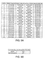
- the above-described arrangement also includes the following embodiment. That is, as for the cell detection signals from the battery modules, for example, a value (7: 0xAA is set to the cell absence signal, as shown in FIGS. 9A and 9B . This value is different from the abnormal signal ( value 0xFF) used for abnormality determination in the normal use mode of the battery pack.
- the absence of cells and the presence of cells in each battery module are determined by the cell arrangement state determiner 310.
- the battery module capacity determiner 312 determines the capacity of each battery module.
- the intra battery module cell count determiner 313 determines the number of cells in each battery module.
- the battery module voltage determiner 314 determines the output voltage of each battery module.
- the arm output voltage determiner 315 determines the output voltage of each arm.
- the matching determiner 316 for the capacity between the battery modules in an arm determines matching of the capacity between the battery modules in each arm.
- the matching determiner 317 for the voltage between the arms determines matching of the voltage between the arms.
- the present invention holds even when only determining the type of each battery module as the first embodiment. That is, if an unfitted (unregistered) battery module exists, the user may be notified that the battery pack is abnormal. The user can thus reexamine the battery pack.
- fit/unfit of a battery pack may be determined by determining the rated voltage, the voltage of each arm, and the capacity of each battery module in each arm using the table described with reference to FIG. 9 .
- the above-described first and second embodiments may be combined. That is, the type of each battery module is determined using the table described with reference to FIG. 8 . Next, fit/unfit is determined by determining the rated voltage, the voltage of each arm, and the capacity of each battery module in each arm using the table described with reference to FIG. 9 . According to this embodiment, it is possible to more correctly grasp the state of the battery pack.
- a battery module inspection method characterized by in a predetermined inspection mode, setting error information to a unique value in advance for each battery module type by the processor of the battery module, and causing the battery module to transmit the error information to the BMU, thereby determining the type of the battery module.
- the BMU internally stores the type of the battery module and the arrangement pattern of battery cells in advance.
- each battery module is diagnosed for maintenance of a cell voltage or cell temperature
- the determiner detects an abnormality of a cell
- an abnormal signal of an abnormal value discriminated from the error information can be transmitted.
- the present invention is not limited to the above embodiments, and the names of the blocks are not limited to those shown in the drawings as long as they perform equivalent operations.
- the embodiments also incorporate integrated blocks or divided blocks.
- the BMU 300 may be provided with circuit boards respectively dedicated to the blocks.
- the blocks may be implemented by software (program).
Landscapes
- Engineering & Computer Science (AREA)
- Power Engineering (AREA)
- Life Sciences & Earth Sciences (AREA)
- Mechanical Engineering (AREA)
- Transportation (AREA)
- Sustainable Energy (AREA)
- Sustainable Development (AREA)
- Electrochemistry (AREA)
- General Chemical & Material Sciences (AREA)
- Chemical Kinetics & Catalysis (AREA)
- Chemical & Material Sciences (AREA)
- Manufacturing & Machinery (AREA)
- Microelectronics & Electronic Packaging (AREA)
- Physics & Mathematics (AREA)
- General Physics & Mathematics (AREA)
- Secondary Cells (AREA)
- Charge And Discharge Circuits For Batteries Or The Like (AREA)
- Battery Mounting, Suspending (AREA)
Applications Claiming Priority (2)
| Application Number | Priority Date | Filing Date | Title |
|---|---|---|---|
| JP2012265090A JP2014110198A (ja) | 2012-12-04 | 2012-12-04 | 電池パック装置、電池パック装置の点検方法及び点検プログラム |
| PCT/JP2013/082448 WO2014087989A1 (ja) | 2012-12-04 | 2013-12-03 | 電池パック装置、電池パック装置の点検方法及びコンピュータ読取可能な媒体 |
Publications (2)
| Publication Number | Publication Date |
|---|---|
| EP2930765A1 true EP2930765A1 (de) | 2015-10-14 |
| EP2930765A4 EP2930765A4 (de) | 2016-12-21 |
Family
ID=50883407
Family Applications (1)
| Application Number | Title | Priority Date | Filing Date |
|---|---|---|---|
| EP13860913.6A Withdrawn EP2930765A4 (de) | 2012-12-04 | 2013-12-03 | Batteriepackvorrichtung, verfahren zur überprüfung der batteriepackvorrichtung und computerlesbares medium |
Country Status (5)
| Country | Link |
|---|---|
| US (1) | US20150263395A1 (de) |
| EP (1) | EP2930765A4 (de) |
| JP (1) | JP2014110198A (de) |
| CN (1) | CN104823303A (de) |
| WO (1) | WO2014087989A1 (de) |
Cited By (1)
| Publication number | Priority date | Publication date | Assignee | Title |
|---|---|---|---|---|
| TWI670913B (zh) * | 2018-11-15 | 2019-09-01 | 豐能科技股份有限公司 | 電池管理系統及其方法 |
Families Citing this family (8)
| Publication number | Priority date | Publication date | Assignee | Title |
|---|---|---|---|---|
| WO2017042892A1 (ja) | 2015-09-08 | 2017-03-16 | 株式会社東芝 | 蓄電池装置、蓄電池システム、方法及びプログラム |
| EP3370298B1 (de) * | 2015-10-30 | 2024-03-06 | Kabushiki Kaisha Toshiba | Batteriesteuerungsvorrichtung und batteriesystem |
| US20170190257A1 (en) * | 2015-12-30 | 2017-07-06 | Thunder Power Hong Kong Ltd. | Smart charging system for electric vehicle battery packs |
| KR102113054B1 (ko) | 2016-03-08 | 2020-05-20 | 가부시끼가이샤 도시바 | 전지 감시 장치 및 방법 |
| EP3547495B1 (de) * | 2016-11-24 | 2023-01-25 | Nec Corporation | Überwachungssystem und überwachungsverfahren |
| US10391864B2 (en) * | 2017-02-08 | 2019-08-27 | Toyota Motor Engineering & Manufacturing North America, Inc. | System to balance high voltage battery for vehicle |
| US11977121B2 (en) | 2020-09-15 | 2024-05-07 | Analog Devices International Unlimited Company | Autonomous battery monitoring system |
| FR3142051A1 (fr) * | 2022-11-15 | 2024-05-17 | Psa Automobiles Sa | Fournitude d’informations relatives à des batteries amovibles d’un véhicule |
Family Cites Families (10)
| Publication number | Priority date | Publication date | Assignee | Title |
|---|---|---|---|---|
| US5825155A (en) * | 1993-08-09 | 1998-10-20 | Kabushiki Kaisha Toshiba | Battery set structure and charge/ discharge control apparatus for lithium-ion battery |
| JP2007205977A (ja) * | 2006-02-03 | 2007-08-16 | Toyota Motor Corp | 二次電池の監視装置 |
| WO2007134320A2 (en) * | 2006-05-15 | 2007-11-22 | A123 Systems, Inc. | Multi-configurable, scalable, redundant battery module with multiple fault tolerance |
| US7349813B2 (en) * | 2006-05-16 | 2008-03-25 | Dresser, Inc. | Fault tolerant power system architecture for fluid flow measurement systems |
| JP5151506B2 (ja) * | 2008-01-28 | 2013-02-27 | 日立工機株式会社 | 電池パックとこれを充電する充電装置及び充電システム |
| JP2010080197A (ja) | 2008-09-25 | 2010-04-08 | Toshiba Corp | 電池パック、電池パック及び充電器の構造体 |
| WO2010079597A1 (ja) * | 2009-01-08 | 2010-07-15 | トヨタ自動車株式会社 | 異常検出装置及び方法、並びに電池製造設備 |
| US8330420B2 (en) * | 2009-04-10 | 2012-12-11 | The Regents Of The University Of Michigan | Dynamically reconfigurable framework for a large-scale battery system |
| JP5469625B2 (ja) * | 2011-03-01 | 2014-04-16 | 株式会社日立製作所 | 電池システム |
| CN103098294B (zh) * | 2011-07-27 | 2015-06-17 | 株式会社日立制作所 | 电池系统 |
-
2012
- 2012-12-04 JP JP2012265090A patent/JP2014110198A/ja active Pending
-
2013
- 2013-12-03 CN CN201380063345.5A patent/CN104823303A/zh active Pending
- 2013-12-03 EP EP13860913.6A patent/EP2930765A4/de not_active Withdrawn
- 2013-12-03 WO PCT/JP2013/082448 patent/WO2014087989A1/ja active Application Filing
-
2015
- 2015-06-02 US US14/728,835 patent/US20150263395A1/en not_active Abandoned
Cited By (1)
| Publication number | Priority date | Publication date | Assignee | Title |
|---|---|---|---|---|
| TWI670913B (zh) * | 2018-11-15 | 2019-09-01 | 豐能科技股份有限公司 | 電池管理系統及其方法 |
Also Published As
| Publication number | Publication date |
|---|---|
| US20150263395A1 (en) | 2015-09-17 |
| EP2930765A4 (de) | 2016-12-21 |
| CN104823303A (zh) | 2015-08-05 |
| JP2014110198A (ja) | 2014-06-12 |
| WO2014087989A1 (ja) | 2014-06-12 |
Similar Documents
| Publication | Publication Date | Title |
|---|---|---|
| EP2930765A1 (de) | Batteriepackvorrichtung, verfahren zur überprüfung der batteriepackvorrichtung und computerlesbares medium | |
| JP4929389B2 (ja) | 電池システム | |
| US20190305386A1 (en) | Fault-tolerant battery management | |
| EP2899839A1 (de) | Batterieverwaltungsvorrichtung, steuerungsverfahren und -programm dafür sowie batterieüberwachungssystem damit | |
| US8015452B2 (en) | Flexible bus architecture for monitoring and control of battery pack | |
| US9716520B2 (en) | Integrated standard-compliant data acquisition device | |
| US10001527B2 (en) | Battery-monitoring system and identifying-information setting method | |
| KR101529381B1 (ko) | 전기자전거용 배터리의 기능검사시스템 | |
| US11411259B2 (en) | Battery control unit | |
| EP3790229A1 (de) | System und verfahren zur inspektion eines slave-bms | |
| CN105637728A (zh) | 蓄电池装置和蓄电池系统 | |
| US11130406B2 (en) | Integrated standard-compliant data acquisition device | |
| WO2014034230A1 (ja) | 電池システム監視装置 | |
| US11396234B2 (en) | Battery system for an electric vehicle, method for operating a battery system, and electric vehicle | |
| JP6172033B2 (ja) | 電池監視装置および電池監視方法 | |
| KR102246451B1 (ko) | 모듈 배터리 시스템 | |
| WO2021192428A1 (ja) | 電池監視装置 | |
| KR20240040012A (ko) | 계층적 구조를 갖는 배터리 관리 시스템 및 이의 운영 방법 | |
| CN116061722A (zh) | 具有触点元件的触点分配诊断功能的模块充电器及其方法 | |
| JP2020021637A (ja) | 電池システム監視装置 |
Legal Events
| Date | Code | Title | Description |
|---|---|---|---|
| PUAI | Public reference made under article 153(3) epc to a published international application that has entered the european phase |
Free format text: ORIGINAL CODE: 0009012 |
|
| 17P | Request for examination filed |
Effective date: 20150602 |
|
| AK | Designated contracting states |
Kind code of ref document: A1 Designated state(s): AL AT BE BG CH CY CZ DE DK EE ES FI FR GB GR HR HU IE IS IT LI LT LU LV MC MK MT NL NO PL PT RO RS SE SI SK SM TR |
|
| AX | Request for extension of the european patent |
Extension state: BA ME |
|
| DAX | Request for extension of the european patent (deleted) | ||
| RA4 | Supplementary search report drawn up and despatched (corrected) |
Effective date: 20161121 |
|
| RIC1 | Information provided on ipc code assigned before grant |
Ipc: B60L 11/18 20060101ALI20161115BHEP Ipc: H01M 10/42 20060101ALI20161115BHEP Ipc: B60L 3/12 20060101ALI20161115BHEP Ipc: H01M 10/48 20060101ALI20161115BHEP Ipc: H02J 7/00 20060101ALI20161115BHEP Ipc: G01R 31/36 20060101ALI20161115BHEP Ipc: B60L 3/00 20060101ALI20161115BHEP Ipc: H01M 2/10 20060101AFI20161115BHEP Ipc: B60L 3/04 20060101ALI20161115BHEP |
|
| STAA | Information on the status of an ep patent application or granted ep patent |
Free format text: STATUS: THE APPLICATION IS DEEMED TO BE WITHDRAWN |
|
| 18D | Application deemed to be withdrawn |
Effective date: 20170620 |