EP2930058A2 - Innenlader mit v-förmiger hubschwinge - Google Patents
Innenlader mit v-förmiger hubschwinge Download PDFInfo
- Publication number
- EP2930058A2 EP2930058A2 EP15000680.7A EP15000680A EP2930058A2 EP 2930058 A2 EP2930058 A2 EP 2930058A2 EP 15000680 A EP15000680 A EP 15000680A EP 2930058 A2 EP2930058 A2 EP 2930058A2
- Authority
- EP
- European Patent Office
- Prior art keywords
- lifting rocker
- chassis
- inloader
- lifting
- wheel
- Prior art date
- Legal status (The legal status is an assumption and is not a legal conclusion. Google has not performed a legal analysis and makes no representation as to the accuracy of the status listed.)
- Granted
Links
Images


Classifications
-
- B—PERFORMING OPERATIONS; TRANSPORTING
- B60—VEHICLES IN GENERAL
- B60P—VEHICLES ADAPTED FOR LOAD TRANSPORTATION OR TO TRANSPORT, TO CARRY, OR TO COMPRISE SPECIAL LOADS OR OBJECTS
- B60P1/00—Vehicles predominantly for transporting loads and modified to facilitate loading, consolidating the load, or unloading
- B60P1/02—Vehicles predominantly for transporting loads and modified to facilitate loading, consolidating the load, or unloading with parallel up-and-down movement of load supporting or containing element
- B60P1/025—Vehicles predominantly for transporting loads and modified to facilitate loading, consolidating the load, or unloading with parallel up-and-down movement of load supporting or containing element with a loading platform inside the wheels of a same axle and being lowerable below the axle
-
- B—PERFORMING OPERATIONS; TRANSPORTING
- B60—VEHICLES IN GENERAL
- B60P—VEHICLES ADAPTED FOR LOAD TRANSPORTATION OR TO TRANSPORT, TO CARRY, OR TO COMPRISE SPECIAL LOADS OR OBJECTS
- B60P1/00—Vehicles predominantly for transporting loads and modified to facilitate loading, consolidating the load, or unloading
- B60P1/02—Vehicles predominantly for transporting loads and modified to facilitate loading, consolidating the load, or unloading with parallel up-and-down movement of load supporting or containing element
-
- B—PERFORMING OPERATIONS; TRANSPORTING
- B60—VEHICLES IN GENERAL
- B60P—VEHICLES ADAPTED FOR LOAD TRANSPORTATION OR TO TRANSPORT, TO CARRY, OR TO COMPRISE SPECIAL LOADS OR OBJECTS
- B60P3/00—Vehicles adapted to transport, to carry or to comprise special loads or objects
- B60P3/002—Vehicles adapted to transport, to carry or to comprise special loads or objects for carrying glass plates
Definitions
- Fig. 1 is an inloader 200 of the type mentioned above schematically, without the usually belonging to parts such as Achshalteböcke, independent suspension, vehicle wheels and transport frame shown.
- the in particular for the transport of large-sized glass panes intended terrorismlader 200 comprises a chassis 3 with two mutually parallel longitudinal beams 4, 4 'and at least one connecting them - forming a rectangular frame construction - cross member 17, and a bolt receptacles 11, 11' on the longitudinal members 4, 4 'pivotally mounted lifting rocker 1, which also has two mutually parallel Hubschwingenarme 5, 5' and this connecting cross member 18, 19.
- the lifting rocker 1 carries one with a plurality of transverse and longitudinal beams 20; 21 reinforced fifth wheel plate 6 with hydraulic cylinders 15, 15 'mounted thereon.
- the lifting rocker 1 is characterized by an overall heavy construction.
- the generic réellelader is particularly intended for the transport of large-scale or large-volume cargo, especially flat glass or precast concrete parts, but also pallets and other bulky goods.
- the réellelader is connected via a pin connection with a tractor and acting on the axle swinging the rear wheels and on the tractor between air suspension bellows or hydraulic cylinder from the low loading position in the higher transport position and brought reversing lifting or lowering.
- the rear wheels with the axle swings have a built-in axle jack axle with a specific camber and wheel projection predetermining swingarm.
- the schilader serve mainly for the transport of large flat glass panes, which must be specially secured and arranged to prevent transport damage.
- the flat glass is provided in A- or L-shaped transport racks.
- the transport frame, and vice versa, the chassis of the réelleladers have mutually corresponding side members, so that when lifting the chassis of the réelleladers the caddy is automatically raised and then moved.
- the fifth wheel plate which carries the pin for connection to a tractor, mounted on a hydraulic or pneumatic lifting rocker, which is operable together with or independent of the air springs of the Einzelradschwingen, so that a common or separate reduction or increase is achievable.
- the bellows of the wheels are relieved accordingly or pressurized with compressed air.
- the rear area is thus a sufficient reduction to push the longitudinal support elements under the support elements of the support frames can.
- a separate lowering and raising device provided in the DE 88 05 461 U1 .
- a separate lowering and raising device provided in a vehicle also referred to as venezlader vehicle.
- the fifth wheel which carries the pin for connection to the tractor, mounted on a so-called lifting rocker, which is supported on an air spring (see. DE 35 07 587 A1 ).
- This air spring is an air bellows, which together with the air springs of the chassis, ie the wheels, together relieved of pressure or pressure is loaded.
- the necessary ground clearance is thus adjustable via the air springs of the Einzelradschwingen and the hydraulic or pneumatic lifting rocker.
- the disadvantage here is that the lifting rocker has a significant weight, whereby the permissible load weight of the réelleladers is reduced.
- the invention has for its object to provide an inner loader of the aforementioned type, in which the permissible load weight increases and the introduction of force can be improved, so that the forces occurring can flow better than in the known lifting rockers.
- this object is achieved in that the lifting rocker is formed from two acute angle to each other in the direction of the fifth wheel tapered Hubschwingenarmen.
- cross member cross member or beam
- transverse beams connecting the oblique struts can be equipped with pneumatic or hydraulic cylinders or other means known per se, for example pneumatic bellows, for moving, in particular lifting and lowering, of the chassis relative to the fifth wheel plate.
- the invention relates to a lifting rocker according to the invention, which on any commercial vehicle, for example on an inloader according to Fig. 1 can be detachably mounted.
- the Figures 10a and 10b show an inner loader 100, which is releasably secured to a chassis 24 of a tractor unit 22 via a fifth wheel coupling 23.
- the fifth wheel 23 is composed of a first, bolted to the chassis 24 fifth wheel plate 25, a king pin 7 and a second, attached to a lifting rocker 1 saddle plate 6 together.
- the Figures 5 and 7 show the devislader 100 in a very simplified form. There, the réellelader 100 is shown by a schematically indicated chassis 3 with side rails 4, 4 'and a new lifting rocker 1.
- the lifting rocker 1 is in the FIGS. 2, 3, 4 and 8th shown in detail. It is connected via axle joints 2, 2 'movably connected to the chassis 3 of the devisladers 100 with longitudinal members 4, 4'.
- the lifting rocker 1 is about joints 2, 2 ', if necessary, via working cylinder 15, 15' (see FIG. 6 and 7 ) pivotally mounted on the chassis 3.
- Hubschwinge 1 A special feature of Hubschwinge 1 are not parallel to each other, but V-shaped, extending Hubschwingenarme 5, 5 '.
- the Hubschwingenarme 5, 5 ' are arranged acute angle to each other and run into the fifth wheel plate 6.
- FIG. 5 and 7 a particularly advantageous embodiment of the side members 4, 4 ', which in a front portion 13 of the chassis 3 via mutually mirror-symmetrically arranged and also V-shaped in a cross member 14 expiring oblique beams 12, 12' pass.
- the arrangement of the oblique beams 12, 12 'and the cross member 10, 14 (see. Fig. 5 ) resembles a truncated uppercase letter A.
- two mutually mirror-symmetrically arranged, lateral guides 8 are provided for moving the fifth wheel plate 6, which are each arranged in a transition region 16 of the Hubschwingenarme 5, 5 'to the fifth wheel plate 6.
- FIGS. 6, 8 and 9 is an oblique arrangement of Hubschwingenarme 5, 5 'relative to the fifth wheel plate 6 can be seen.
- the great advantage is that the V-shaped lifting rocker 1 leads to a better force transmission and also to a material and weight savings.
- the allowable load weight of the réelleladers 100 can be increased.
- the Fig. 10a shows the inner loader 100 in the raised state, in which the whole consisting of the tractor unit 22 and the devislader 100 team is ready to drive.
- the change of an amount B between the chassis 3 and a roadway plane 26 causes a lowering of the réelleladers 100 (see. Fig. 10b ).
- the inner loader 100 touches the road surface 26, so that it can be easily loaded from the rear.
Landscapes
- Engineering & Computer Science (AREA)
- Transportation (AREA)
- Mechanical Engineering (AREA)
- Health & Medical Sciences (AREA)
- Public Health (AREA)
- Vehicle Body Suspensions (AREA)
- Pallets (AREA)
Abstract
Description
- Die Erfindung betrifft einen Innenlader, umfassend:
- ein Chassis mit zwei parallel zueinander angeordneten Fahrzeuglängsträgern, an denen Achshalteböcke mit gefederten Einzelradschwingen zur Aufnahme von Fahrzeugrädern befestigt sind,
- und eine über Bolzenaufnahmen an den Fahrzeuglängsträgern gelagerte, hydraulisch oder pneumatisch angetriebene Hubschwinge zur Aufnahme einer Sattelplatte, die einen Zapfen zum Anschließen an eine Sattelzugmaschine trägt.
- In
Fig. 1 ist ein Innenlader 200 der eingangs genannten Art schematisch, ohne die dazu üblicherweise gehörenden Teile, wie Achshalteböcke, Einzelradaufhängung, Fahrzeugräder und Transportgestell zu zeigen, dargestellt. Der insbesondere für den Transport von großformatigen Glasscheiben bestimmte Innenlader 200 umfasst ein Chassis 3 mit zwei zueinander parallel verlaufenden Längsträgern 4, 4' und wenigstens einem diese verbindenden - eine rechteckige Rahmenkonstruktion bildend - Querträger 17, sowie eine über Bolzenaufnahmen 11, 11' an den Längsträgern 4, 4' schwenkbar gelagerte Hubschwinge 1, welche ebenso zwei zueinander parallel angeordnete Hubschwingenarme 5, 5' und diese verbindende Querträger 18, 19 aufweist. Die Hubschwinge 1 trägt eine mit mehreren Quer- und Längsbalken 20; 21 verstärkte Sattelplatte 6 mit daran gelagerten Hydraulikzylindern 15, 15'. Die Hubschwinge 1 zeichnet sich durch eine insgesamt schwere Bauweise aus. - Der gattungsgemäße Innenlader ist insbesondere für den Transport großflächiger oder großvolumiger Transportgüter, insbesondere von Flachglas oder Betonfertigteilen, aber auch Paletten und anderer sperrigen Transportgüter bestimmt. Der Innenlader wird über eine Zapfenverbindung mit einer Sattelzugmaschine verbunden und über auf die Achsschwingen der Hinterräder und auf die Sattelzugmaschine einwirkende Luftfederbälge oder Hydraulikzylinder aus der niedrigen Ladestellung in die höhere Transportstellung und umgekehrt anhebend bzw. absenkend gebracht. Die Hinterräder mit den Achsschwingen verfügen über einen in einen Achsbock integrierten Achsbolzen mit einer einen bestimmten Radsturz und Radvorsprung vorgebenden Schwingenlagerung.
- Die Innenlader dienen vor allem zum Transport großer Flachglasscheiben, die besonders gesichert und angeordnet werden müssen, um Transportschäden zu vermeiden. Das Flachglas wird in A- oder L-förmigen Transportgestellen bereitgestellt. Das Transportgestell, und umgekehrt auch das Fahrgestell des Innenladers, weisen zueinander korrespondierende Längsträger auf, so dass beim Anheben des Fahrgestells des Innenladers das Transportgestell automatisch mit angehoben und anschließend verfahren wird. Zum Anheben werden die dem Fahrgestell zugeordneten Luftfederbälge, oder Hydraulikzylinder, die vorher entlastet worden waren, wieder mit Druckluft beaufschlagt, so dass sich das Fahrgestell, das mit den Hinterrädern über Achsschwingen verbunden ist, entsprechend anhebt und das Transportgestell mit hochhebt.
- Derartige Innenlader sind auch in
DE 35 07 587 A1 beschrieben. Bei derartigen Innenladern werden die Hinterräder über die Achsschwingen gehalten, die ihrerseits über ein Schwenklager am Fahrgestell gelagert sind. Dieses Schwenklager oder Schwingenlager ist im Endbereich über eine Gegenplatte gehalten, die mit Schrauben verschraubt ist. Die nähere Ausgestaltung ergibt sich außerdem ausDE 196 05 710 A1 . - Um das gesamte Chassis anheben bzw. absenken zu können, ist die Sattelplatte, die den Zapfen zum Anschließen an einer Zugmaschine trägt, an einer hydraulischen oder pneumatischen Hubschwinge angebracht, die gemeinsam mit oder unabhängig von den Luftfedern der Einzelradschwingen betätigbar ist, so dass eine gemeinsame oder getrennte Absenkung oder Anhebung erzielbar ist.
- Zum Absenken und Anheben des Fahrgestells werden die Luftfederbälge der Räder entsprechend entlastet oder mit Druckluft beaufschlagt. Für den hinteren Bereich erfolgt damit eine ausreichende Absenkung, um die Längstragelemente unter die Tragelemente der Traggestelle schieben zu können. Für den vorderen Teil ist beispielsweise in der
DE 88 05 461 U1 eine gesonderte Absenk- und Anhebeinrichtung vorgesehen. Bei einem auch als Innenlader bezeichneten Fahrzeug ist die Sattelkupplung, die den Zapfen zum Anschließen an die Sattelzugmaschine trägt, an einer sogenannten Hubschwinge angebracht, die auf einer Luftfeder abgestützt ist (vgl.DE 35 07 587 A1 ). Bei dieser Luftfeder handelt es sich um einen Luftbalg, der mit den Luftfedern des Fahrgestells, d.h. der Räder, zusammen druckentlastet bzw. druckbelastet wird. Dadurch ist es möglich, das gesamte Fahrgestell mit dem darin angeordneten Transportgestell für das Glas anzuheben bzw. abzusenken, und zwar bis auf die Restbodenfreiheit, mit der das Fahrzeug noch verfahren werden kann. Die notwendige Bodenfreiheit wird dann durch das Füllen der einzelnen Luftbälge bzw. Luftfedern wieder hergestellt. Nachteilig hierbei ist jedoch, dass eine Restbodenfreiheit verbleibt, die das Aufnehmen des Transportgestells mit den Glaspaketen erschwert und die insbesondere nicht die Aufnahme aller im Verkehr befindlicher Transportgestelle ohne weiteres zulässt. Grund hierfür ist, dass sowohl die Luftfederung der Räder, d.h. also des Fahrgestells, als auch der Luftbalg, der der vorderen Ladeplattform bzw. dieser Sattelkupplung zugeordnet ist, nur über einen geringen Hub verfügen. - Die notwendige Bodenfreiheit ist also über die Luftfedern der Einzelradschwingen und der hydraulischen bzw. pneumatischen Hubschwinge einstellbar. Nachteilig dabei ist, dass die Hubschwinge ein nicht unerhebliches Gewicht aufweist, wodurch das zulässige Ladegewicht des Innenladers reduziert ist.
- Der Erfindung liegt die Aufgabe zugrunde, einen Innenlader der vorgenannten Art bereitzustellen, bei dem das zulässige Ladegewicht erhöht und die Krafteinleitung verbessert werden kann, so dass die auftretenden Kräfte besser als bei den bekannten Hubschwingen fließen können.
- Gemäß der Erfindung wird diese Aufgabe dadurch gelöst, dass die Hubschwinge aus zwei zueinander spitzwinkelig in Richtung Sattelplatte zulaufenden Hubschwingenarmen gebildet ist.
- Hierdurch wird eine bessere Krafteinleitung und eine leichtere Bauweise erreicht. Dies führt insbesondere zu einer Gewichts- und Kosteneinsparung sowie zu einer Erhöhung der Nutzlast des Innenladers.
- Zur Gewichts- und Kosteneinsparung kann auch eine "Abspeckung" des Chassis in seinem vorderen, auf die Sattelplatte zeigenden Bereich beitragen, indem die beiden Längsträger über zueinander spiegelsymmetrisch angeordnete und aufeinander zulaufende Schrägholme in wenigstens einen diese verbindenden Querträger übergehen. Dies kann das Gewicht des gesamten Chassis verringern.
- Zur Verbesserung der Stabilität der Hubschwinge können die Hubschwingenarme miteinander über wenigstens eine Traverse (Querträger bzw. -balken) verbunden sein.
- Weiterhin kann der die Schrägholme verbindende Querträger mit Pneumatik- oder Hydraulikzylindern oder anderen an sich bekannten Mitteln, beispielsweise Luftbalg, zum Bewegen, insbesondere Heben und Senken des Chassis gegenüber der Sattelplatte bestückt sein.
- Schließlich bezieht sich die Erfindung auf eine erfindungsgemäße Hubschwinge, welche an beliebigem Nutzfahrzeug, beispielsweise an einem Innenlader gemäß
Fig. 1 lösbar einmontiert werden kann. - Die Erfindung ist nachstehend in einem Ausführungsbeispiel anhand der Zeichnung näher erläutert. Die Figuren zeigen:
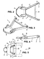
- Fig. 1
- eine Hubschwinge gemäß Stand der Technik, in einer perspektivischen Ansicht;
- Fig. 2
- eine V-förmige Hubschwinge gemäß Erfindung, in einer Draufsicht auf Sattelplatte;
- Fig. 3
- eine perspektivische Ansicht der Hubschwinge gemäß
Fig. 2 ; - Fig. 4
- eine Seitenansicht der Hubschwinge gemäß
Fig. 2 ; - Fig. 5
- die in ein Chassis des Innenladers eingebaute Hubschwinge gemäß Erfindung;
- Fig. 6
- eine Seitenansicht des Chassis in seinem vorderen Bereich, mit eingebauter Hubschwinge gemäß Erfindung;
- Fig. 7
- eine perspektivische Ansicht des Chassis mit eingebauter Hubschwinge;
- Fig. 8
- eine Frontansicht der Hubschwinge gemäß Erfindung;
- Fig. 9
- die in das Chassis eingebaute Hubschwinge, in einer Frontansicht und
- Fig. 10a und 10b
- jeweils ein Sattelkraftfahrzeug, bestehend aus einer Sattelzugmaschine und einem Innenlader mit erfindungsgemäßer Hubschwinge, im angehobenen und abgesenkten Zustand des Innenladers, in einer schematischen Seitenansicht.
- Die
Figuren 10a und 10b zeigen einen Innenlader 100, welcher an einem Fahrgestell 24 einer Sattelzugmaschine 22 über eine Sattelkupplung 23 lösbar befestigt ist. Die Sattelkupplung 23 setzt sich aus einer ersten, am Fahrgestell 24 aufgeschraubten Sattelplatte 25, einem Königszapfen 7 und einer zweiter, an einer Hubschwinge 1 angebrachten Sattelplatte 6 zusammen. Auch dieFiguren 5 und7 zeigen den Innenlader 100 in einer sehr vereinfachten Form. Dort ist der Innenlader 100 durch ein schematisch angedeutetes Chassis 3 mit Längsträgern 4, 4' und einer neuartigen Hubschwinge 1 gezeigt. - Die Hubschwinge 1 gemäß Erfindung ist in den
Figuren 2, 3, 4 und8 detailliert dargestellt. Sie ist über Achsgelenke 2, 2' beweglich mit dem Chassis 3 des Innenladers 100 mit Längsträgern 4, 4' verbunden. Die Hubschwinge 1 ist über Gelenke 2, 2', soweit notwendig, über Arbeitszylinder 15, 15' (vergl.Fig. 6 und 7 ) verschwenkbar am Chassis 3 angeordnet. - Eine Besonderheit der Hubschwinge 1 sind die nicht parallel zueinander, sondern V-förmig, verlaufenden Hubschwingenarme 5, 5'. Die Hubschwingenarme 5, 5' sind zueinander spitzwinkelig angeordnet und laufen in die Sattelplatte 6 aus.
- Wie die
Figuren 5 und7 zeigen, ist die Hubschwinge 1 mit einem quer verlaufenden und die Hubschwingenarme 5, 5' miteinander verbindenden Querträger 10 versteift. Der Einsatz des Querträgers 10 ist optional. Zusätzlich sind Aufnahmen 9, 9' (vgl.Fig. 2 ) für zwei schematisch angedeutete Hydraulikzylinder 15, 15' (vgl.Figuren 6 und 7 ) vorgesehen. - Weiterhin zeigen die
Figuren 5 und7 eine besonders vorteilhafte Ausgestaltung der Längsträger 4, 4', welche in einem vorderen Bereich 13 des Chassis 3 über zueinander spiegelsymmetrisch angeordnete und ebenso V-förmig in einen Querträger 14 auslaufende Schrägholme 12, 12' übergehen. Die Anordnung der Schrägholme 12, 12' und der Querträger 10, 14 (vgl.Fig. 5 ) ähnelt einem abgeschnittenen Großbuchstaben A. - Optional sind zwei zueinander spiegelsymmetrisch angeordnete, seitliche Führungen 8 (vgl.
Figuren 4 und8 ) zum Verschieben der Sattelplatte 6 vorgesehen, welche jeweils in einem Übergangsbereich 16 der Hubschwingenarme 5, 5' zur Sattelplatte 6 angeordnet sind. - Den
Figuren 6, 8 und 9 ist eine schräge Anordnung der Hubschwingenarme 5, 5' gegenüber der Sattelplatte 6 zu entnehmen. Die Hubschwingenarme 5, 5' sind spiegelsymmetrisch zu einer mit Strichlinie angedeuteten Symmetrieebene E angeordnet. Daraus ergibt sich auch eine V-förmige, jedoch stumpfwinklige Anordnung der Hubschwingenarme 5, 5' zueinander (Figuren 8 und 9 ). - Vom großen Vorteil ist, dass die V-förmige Hubschwinge 1 zu einer besseren Krafteinleitung und außerdem zu einer Material- und Gewichtsersparnis führt. Damit kann das zulässige Ladegewicht des Innenladers 100 erhöht werden.
- Die
Fig. 10a zeigt den Innenlader 100 im angehobenen Zustand, bei dem das ganze aus der Sattelzugmaschine 22 und dem Innenlader 100 bestehende Gespann fahrbereit ist. Die Änderung eines Betrages B zwischen dem Chassis 3 und einer Fahrbahnebene 26 bewirkt eine Absenkung des Innenladers 100 (vgl.Fig. 10b ). Abgesenkt wird mittels der erfindungsgemäßen Hubschwinge 1 im Bereich der Sattelkupplung 23 und mittels einer hydraulischen bzw. pneumatischen Achsfederung an den Fahrzeugsachsen. Der Innenlader 100 berührt die Fahrbahnebene 26, so dass er sehr einfach von hinten beladen werden kann. - Natürlich ist die Erfindung nicht auf das oben dargestellte Ausführungsbeispiel beschränkt. Weitere Ausgestaltungen sind möglich, ohne den Grundgedanken der vorliegenden Erfindung zu verlassen.
Bezugszeichenliste 1 Hubschwinge 2, 2' Achsgelenk 3 Chassis 4, 4' Längsträger 5, 5' Hubschwingenarm 6 Sattelplatte 7 Königszapfen 8 Führung 9, 9' Aufnahme 10 Querträger 11, 11' Bolzenaufnahme 12, 12' Schrägholm 13 vorderer Bereich 14 Querträger 15, 15' Hydraulikzylinder 16 Übergangsbereich 17 Querträger ( Fig. 1 )18 Querträger ( Fig. 1 )19 Querträger ( Fig. 1 )20 Querbalken ( Fig. 1 21 Längsbalken ( Fig. 1 )22 Sattelzugmaschine ( Fig. 10 )23 Sattelkupplung ( Fig. 10 )24 Fahrgestell 25 Sattelplatte (v. 24) 26 Fahrbahnebene 100 Innenlader 200 Innenlader ( Fig. 1 )B Betrag ( Fig. 10a E Symmetrieebene ( Fig.8 )
Claims (7)
- Innenlader (100), umfassend:- ein Chassis (3) mit zwei parallel zueinander angeordneten Längsträgern (4, 4'), an denen Achshalteböcke mit gefederten Einzelradschwingen zur Aufnahme von Fahrzeugrädern befestigt sind,- und eine über Bolzenaufnahmen (11, 11') an den Längsträgern (4, 4') gelagerte, hydraulisch oder pneumatisch angetriebene Hubschwinge (1) zur Aufnahme einer Sattelplatte (6), die einen Zapfen (7) zum Anschließen an eine Sattelzugmaschine trägt,dadurch gekennzeichnet, dass die Hubschwinge (1) aus zwei zueinander spitzwinkelig in Richtung Sattelplatte (6) zulaufenden Hubschwingenarmen (5, 5') gebildet ist.
- Innenlader (100) nach Anspruch 1, dadurch gekennzeichnet, dass die Hubschwinge (1) wenigstens einen die Hubschwingenarme (5, 5') miteinander verbindenden Querträger (10) aufweist.
- Innenlader (100) nach Anspruch 1 oder 2, dadurch gekennzeichnet, dass die Längsträger (4, 4') in einem vorderen Bereich (13) des Chassis (3) über zueinander spiegelsymmetrisch angeordnete und aufeinander zulaufende Schrägholme (12, 12') in wenigstens einen diese verbindenden Querträger (14) übergehen.
- Innenlader (100) nach Anspruch 3, dadurch gekennzeichnet, dass die Fahrzeuglängsträger (4, 4') im vorderen Bereich (13) in Draufsicht auf das Chassis (3) etwa einen abgeschnittenen Großbuchstaben A ergeben.
- Innenlader (100) nach einem der Ansprüche 1 bis 4, dadurch gekennzeichnet, dass Pneumatik- oder Hydraulikzylindern (15, 15') vorgesehen sind, mittels derer das Chassis (3) gegenüber der Sattelplatte (6) angehoben bzw. absenkbar ist.
- Innenlader (100) nach einem der Ansprüche 1 bis 5, dadurch gekennzeichnet, dass die Hubschwinge (1) zueinander spiegelsymmetrisch angeordnete, seitliche Führungen (8) aufweist, welche jeweils in einem Übergangsbereich (16) der Hubschwingenarme (5, 5') zur Sattelplatte (6) liegen und etwa senkrecht zur Sattelplatte (6) verlaufen.
- Hubschwinge (1) zur lösbaren Montage am Chassis (3) eines Innenladers (100), aufweisend zwei zueinander spitzwinkelig in Richtung Sattelplatte (6) zulaufende Hubschwingenarme (5, 5').
Applications Claiming Priority (1)
| Application Number | Priority Date | Filing Date | Title |
|---|---|---|---|
| DE202014101419.5U DE202014101419U1 (de) | 2014-03-26 | 2014-03-26 | V-förmige Hubschwinge |
Publications (3)
| Publication Number | Publication Date |
|---|---|
| EP2930058A2 true EP2930058A2 (de) | 2015-10-14 |
| EP2930058A3 EP2930058A3 (de) | 2015-12-23 |
| EP2930058B1 EP2930058B1 (de) | 2020-04-01 |
Family
ID=50556504
Family Applications (1)
| Application Number | Title | Priority Date | Filing Date |
|---|---|---|---|
| EP15000680.7A Active EP2930058B1 (de) | 2014-03-26 | 2015-03-09 | Innenlader mit v-förmiger hubschwinge |
Country Status (2)
| Country | Link |
|---|---|
| EP (1) | EP2930058B1 (de) |
| DE (1) | DE202014101419U1 (de) |
Citations (3)
| Publication number | Priority date | Publication date | Assignee | Title |
|---|---|---|---|---|
| DE3507587A1 (de) | 1985-03-04 | 1986-09-04 | Fahrzeugbau Langendorf GmbH & Co KG, 4355 Waltrop | Als auflieger einer sattelzugmaschine ausgebildeter innenlader fuer den strassenverkehr von transportgestellen, insbesondere fuer den flachglastransport |
| DE8805461U1 (de) | 1988-04-25 | 1988-08-18 | Vöcking, Theodor, 4422 Ahaus | Glastransportsattelanhänger |
| DE19605710A1 (de) | 1996-02-16 | 1997-08-21 | Orthaus Fahrzeugwerk | Innenlader mit verstellbarer Achsschwingenlagerung |
Family Cites Families (4)
| Publication number | Priority date | Publication date | Assignee | Title |
|---|---|---|---|---|
| US2905481A (en) * | 1958-03-31 | 1959-09-22 | Arthur G Schramm | Manually operated open bed elevatable trailers |
| US3271042A (en) * | 1964-01-09 | 1966-09-06 | Flodin Inc | Trailer with lift-type load bed |
| DE2307430C3 (de) * | 1973-02-15 | 1979-01-04 | Peter Bauer Gmbh & Co Kg, 5000 Koeln | Sattelanhänger für Sattelzüge mit üblichen Zugmaschinen |
| US3861716A (en) * | 1973-04-30 | 1975-01-21 | Binkley Co | Platform lift transporter |
-
2014
- 2014-03-26 DE DE202014101419.5U patent/DE202014101419U1/de not_active Expired - Lifetime
-
2015
- 2015-03-09 EP EP15000680.7A patent/EP2930058B1/de active Active
Patent Citations (3)
| Publication number | Priority date | Publication date | Assignee | Title |
|---|---|---|---|---|
| DE3507587A1 (de) | 1985-03-04 | 1986-09-04 | Fahrzeugbau Langendorf GmbH & Co KG, 4355 Waltrop | Als auflieger einer sattelzugmaschine ausgebildeter innenlader fuer den strassenverkehr von transportgestellen, insbesondere fuer den flachglastransport |
| DE8805461U1 (de) | 1988-04-25 | 1988-08-18 | Vöcking, Theodor, 4422 Ahaus | Glastransportsattelanhänger |
| DE19605710A1 (de) | 1996-02-16 | 1997-08-21 | Orthaus Fahrzeugwerk | Innenlader mit verstellbarer Achsschwingenlagerung |
Also Published As
| Publication number | Publication date |
|---|---|
| EP2930058A3 (de) | 2015-12-23 |
| EP2930058B1 (de) | 2020-04-01 |
| DE202014101419U1 (de) | 2014-04-08 |
Similar Documents
| Publication | Publication Date | Title |
|---|---|---|
| DE2449815A1 (de) | Vorrichtung zum anheben von fahrzeugen | |
| EP0446756A1 (de) | Strassengängig transportierbare Brechanlage | |
| DE2944289A1 (de) | Hebefahrzeug | |
| DE2141816A1 (de) | Tiefladeanhaengerfahrzeug | |
| DE102008006119B3 (de) | Mobilkran und Verfahren zur Montage | |
| DE1160740B (de) | Aufsattelbarer Muldenkipper | |
| DE2837398A1 (de) | Fahrzeugkran | |
| EP2930058B1 (de) | Innenlader mit v-förmiger hubschwinge | |
| DE2809628A1 (de) | Fahrzeuggespann mit sattelaufleger und sattelschlepper | |
| AT507330A1 (de) | Rahmen zur befestigung einer anbauvorrichtung an einem lastkraftwagen | |
| EP0286576B1 (de) | Transportfahrzeug | |
| WO2002100755A1 (de) | Flurförderfahrzeug | |
| DE102012101272B3 (de) | Sattelzug, umfassend eine Sattelzugmaschine und einen Innenlader | |
| DE19728822A1 (de) | Anbaunachlauffahrwerk | |
| DE9306949U1 (de) | Ladevorrichtung für Lastträger | |
| EP2537982B1 (de) | Verfahren und Vorrichtung zum Umrüsten eines Strassenfertigers sowie ein Strassenfertiger | |
| DE3423544C2 (de) | ||
| AT519662B1 (de) | Anhänger mit auswechselbarem Aufbau | |
| DE4101660A1 (de) | Road-trailer-innenlader mit hebbarer achsschwinge | |
| EP2711211A2 (de) | Radaufhängung für ein Schwerlast-Transportfahrzeug sowie ein eine derartige Radaufhäungung verwendendes Schwerlast-Transportfahrzeug | |
| DE3017738C2 (de) | ||
| DE2609928A1 (de) | Hydraulisch absenkbare ladeplattform fuer lkw oder anhaenger | |
| AT390046B (de) | Vorrichtung zum verladen von fahrzeugen von einer rampe od.dgl. auf eisenbahnwaggons | |
| DE2945438A1 (de) | Lastfahrzeug | |
| DE8510250U1 (de) | Lkw oder Anhänger mit einem Wechselaufbau |
Legal Events
| Date | Code | Title | Description |
|---|---|---|---|
| PUAI | Public reference made under article 153(3) epc to a published international application that has entered the european phase |
Free format text: ORIGINAL CODE: 0009012 |
|
| AK | Designated contracting states |
Kind code of ref document: A2 Designated state(s): AL AT BE BG CH CY CZ DE DK EE ES FI FR GB GR HR HU IE IS IT LI LT LU LV MC MK MT NL NO PL PT RO RS SE SI SK SM TR |
|
| AX | Request for extension of the european patent |
Extension state: BA ME |
|
| PUAL | Search report despatched |
Free format text: ORIGINAL CODE: 0009013 |
|
| AK | Designated contracting states |
Kind code of ref document: A3 Designated state(s): AL AT BE BG CH CY CZ DE DK EE ES FI FR GB GR HR HU IE IS IT LI LT LU LV MC MK MT NL NO PL PT RO RS SE SI SK SM TR |
|
| AX | Request for extension of the european patent |
Extension state: BA ME |
|
| RIC1 | Information provided on ipc code assigned before grant |
Ipc: B60P 1/02 20060101AFI20151119BHEP Ipc: B60P 3/00 20060101ALI20151119BHEP |
|
| 17P | Request for examination filed |
Effective date: 20160623 |
|
| RBV | Designated contracting states (corrected) |
Designated state(s): AL AT BE BG CH CY CZ DE DK EE ES FI FR GB GR HR HU IE IS IT LI LT LU LV MC MK MT NL NO PL PT RO RS SE SI SK SM TR |
|
| STAA | Information on the status of an ep patent application or granted ep patent |
Free format text: STATUS: EXAMINATION IS IN PROGRESS |
|
| 17Q | First examination report despatched |
Effective date: 20190401 |
|
| GRAP | Despatch of communication of intention to grant a patent |
Free format text: ORIGINAL CODE: EPIDOSNIGR1 |
|
| STAA | Information on the status of an ep patent application or granted ep patent |
Free format text: STATUS: GRANT OF PATENT IS INTENDED |
|
| INTG | Intention to grant announced |
Effective date: 20191011 |
|
| GRAJ | Information related to disapproval of communication of intention to grant by the applicant or resumption of examination proceedings by the epo deleted |
Free format text: ORIGINAL CODE: EPIDOSDIGR1 |
|
| GRAS | Grant fee paid |
Free format text: ORIGINAL CODE: EPIDOSNIGR3 |
|
| GRAJ | Information related to disapproval of communication of intention to grant by the applicant or resumption of examination proceedings by the epo deleted |
Free format text: ORIGINAL CODE: EPIDOSDIGR1 |
|
| GRAL | Information related to payment of fee for publishing/printing deleted |
Free format text: ORIGINAL CODE: EPIDOSDIGR3 |
|
| STAA | Information on the status of an ep patent application or granted ep patent |
Free format text: STATUS: EXAMINATION IS IN PROGRESS |
|
| GRAR | Information related to intention to grant a patent recorded |
Free format text: ORIGINAL CODE: EPIDOSNIGR71 |
|
| STAA | Information on the status of an ep patent application or granted ep patent |
Free format text: STATUS: GRANT OF PATENT IS INTENDED |
|
| GRAA | (expected) grant |
Free format text: ORIGINAL CODE: 0009210 |
|
| STAA | Information on the status of an ep patent application or granted ep patent |
Free format text: STATUS: THE PATENT HAS BEEN GRANTED |
|
| INTC | Intention to grant announced (deleted) | ||
| AK | Designated contracting states |
Kind code of ref document: B1 Designated state(s): AL AT BE BG CH CY CZ DE DK EE ES FI FR GB GR HR HU IE IS IT LI LT LU LV MC MK MT NL NO PL PT RO RS SE SI SK SM TR |
|
| INTG | Intention to grant announced |
Effective date: 20200224 |
|
| REG | Reference to a national code |
Ref country code: GB Ref legal event code: FG4D Free format text: NOT ENGLISH |
|
| REG | Reference to a national code |
Ref country code: CH Ref legal event code: EP Ref country code: AT Ref legal event code: REF Ref document number: 1250943 Country of ref document: AT Kind code of ref document: T Effective date: 20200415 |
|
| REG | Reference to a national code |
Ref country code: DE Ref legal event code: R096 Ref document number: 502015012117 Country of ref document: DE |
|
| REG | Reference to a national code |
Ref country code: IE Ref legal event code: FG4D Free format text: LANGUAGE OF EP DOCUMENT: GERMAN |
|
| PG25 | Lapsed in a contracting state [announced via postgrant information from national office to epo] |
Ref country code: BG Free format text: LAPSE BECAUSE OF FAILURE TO SUBMIT A TRANSLATION OF THE DESCRIPTION OR TO PAY THE FEE WITHIN THE PRESCRIBED TIME-LIMIT Effective date: 20200701 |
|
| REG | Reference to a national code |
Ref country code: NL Ref legal event code: MP Effective date: 20200401 |
|
| REG | Reference to a national code |
Ref country code: LT Ref legal event code: MG4D |
|
| PG25 | Lapsed in a contracting state [announced via postgrant information from national office to epo] |
Ref country code: PT Free format text: LAPSE BECAUSE OF FAILURE TO SUBMIT A TRANSLATION OF THE DESCRIPTION OR TO PAY THE FEE WITHIN THE PRESCRIBED TIME-LIMIT Effective date: 20200817 Ref country code: LT Free format text: LAPSE BECAUSE OF FAILURE TO SUBMIT A TRANSLATION OF THE DESCRIPTION OR TO PAY THE FEE WITHIN THE PRESCRIBED TIME-LIMIT Effective date: 20200401 Ref country code: FI Free format text: LAPSE BECAUSE OF FAILURE TO SUBMIT A TRANSLATION OF THE DESCRIPTION OR TO PAY THE FEE WITHIN THE PRESCRIBED TIME-LIMIT Effective date: 20200401 Ref country code: NL Free format text: LAPSE BECAUSE OF FAILURE TO SUBMIT A TRANSLATION OF THE DESCRIPTION OR TO PAY THE FEE WITHIN THE PRESCRIBED TIME-LIMIT Effective date: 20200401 Ref country code: CZ Free format text: LAPSE BECAUSE OF FAILURE TO SUBMIT A TRANSLATION OF THE DESCRIPTION OR TO PAY THE FEE WITHIN THE PRESCRIBED TIME-LIMIT Effective date: 20200401 Ref country code: SE Free format text: LAPSE BECAUSE OF FAILURE TO SUBMIT A TRANSLATION OF THE DESCRIPTION OR TO PAY THE FEE WITHIN THE PRESCRIBED TIME-LIMIT Effective date: 20200401 Ref country code: GR Free format text: LAPSE BECAUSE OF FAILURE TO SUBMIT A TRANSLATION OF THE DESCRIPTION OR TO PAY THE FEE WITHIN THE PRESCRIBED TIME-LIMIT Effective date: 20200702 Ref country code: IS Free format text: LAPSE BECAUSE OF FAILURE TO SUBMIT A TRANSLATION OF THE DESCRIPTION OR TO PAY THE FEE WITHIN THE PRESCRIBED TIME-LIMIT Effective date: 20200801 Ref country code: NO Free format text: LAPSE BECAUSE OF FAILURE TO SUBMIT A TRANSLATION OF THE DESCRIPTION OR TO PAY THE FEE WITHIN THE PRESCRIBED TIME-LIMIT Effective date: 20200701 |
|
| PG25 | Lapsed in a contracting state [announced via postgrant information from national office to epo] |
Ref country code: RS Free format text: LAPSE BECAUSE OF FAILURE TO SUBMIT A TRANSLATION OF THE DESCRIPTION OR TO PAY THE FEE WITHIN THE PRESCRIBED TIME-LIMIT Effective date: 20200401 Ref country code: HR Free format text: LAPSE BECAUSE OF FAILURE TO SUBMIT A TRANSLATION OF THE DESCRIPTION OR TO PAY THE FEE WITHIN THE PRESCRIBED TIME-LIMIT Effective date: 20200401 Ref country code: LV Free format text: LAPSE BECAUSE OF FAILURE TO SUBMIT A TRANSLATION OF THE DESCRIPTION OR TO PAY THE FEE WITHIN THE PRESCRIBED TIME-LIMIT Effective date: 20200401 |
|
| PG25 | Lapsed in a contracting state [announced via postgrant information from national office to epo] |
Ref country code: AL Free format text: LAPSE BECAUSE OF FAILURE TO SUBMIT A TRANSLATION OF THE DESCRIPTION OR TO PAY THE FEE WITHIN THE PRESCRIBED TIME-LIMIT Effective date: 20200401 |
|
| REG | Reference to a national code |
Ref country code: DE Ref legal event code: R097 Ref document number: 502015012117 Country of ref document: DE |
|
| PG25 | Lapsed in a contracting state [announced via postgrant information from national office to epo] |
Ref country code: ES Free format text: LAPSE BECAUSE OF FAILURE TO SUBMIT A TRANSLATION OF THE DESCRIPTION OR TO PAY THE FEE WITHIN THE PRESCRIBED TIME-LIMIT Effective date: 20200401 Ref country code: RO Free format text: LAPSE BECAUSE OF FAILURE TO SUBMIT A TRANSLATION OF THE DESCRIPTION OR TO PAY THE FEE WITHIN THE PRESCRIBED TIME-LIMIT Effective date: 20200401 Ref country code: SM Free format text: LAPSE BECAUSE OF FAILURE TO SUBMIT A TRANSLATION OF THE DESCRIPTION OR TO PAY THE FEE WITHIN THE PRESCRIBED TIME-LIMIT Effective date: 20200401 Ref country code: EE Free format text: LAPSE BECAUSE OF FAILURE TO SUBMIT A TRANSLATION OF THE DESCRIPTION OR TO PAY THE FEE WITHIN THE PRESCRIBED TIME-LIMIT Effective date: 20200401 Ref country code: DK Free format text: LAPSE BECAUSE OF FAILURE TO SUBMIT A TRANSLATION OF THE DESCRIPTION OR TO PAY THE FEE WITHIN THE PRESCRIBED TIME-LIMIT Effective date: 20200401 |
|
| PLBE | No opposition filed within time limit |
Free format text: ORIGINAL CODE: 0009261 |
|
| STAA | Information on the status of an ep patent application or granted ep patent |
Free format text: STATUS: NO OPPOSITION FILED WITHIN TIME LIMIT |
|
| PG25 | Lapsed in a contracting state [announced via postgrant information from national office to epo] |
Ref country code: SK Free format text: LAPSE BECAUSE OF FAILURE TO SUBMIT A TRANSLATION OF THE DESCRIPTION OR TO PAY THE FEE WITHIN THE PRESCRIBED TIME-LIMIT Effective date: 20200401 Ref country code: PL Free format text: LAPSE BECAUSE OF FAILURE TO SUBMIT A TRANSLATION OF THE DESCRIPTION OR TO PAY THE FEE WITHIN THE PRESCRIBED TIME-LIMIT Effective date: 20200401 |
|
| 26N | No opposition filed |
Effective date: 20210112 |
|
| PG25 | Lapsed in a contracting state [announced via postgrant information from national office to epo] |
Ref country code: SI Free format text: LAPSE BECAUSE OF FAILURE TO SUBMIT A TRANSLATION OF THE DESCRIPTION OR TO PAY THE FEE WITHIN THE PRESCRIBED TIME-LIMIT Effective date: 20200401 |
|
| PG25 | Lapsed in a contracting state [announced via postgrant information from national office to epo] |
Ref country code: MC Free format text: LAPSE BECAUSE OF FAILURE TO SUBMIT A TRANSLATION OF THE DESCRIPTION OR TO PAY THE FEE WITHIN THE PRESCRIBED TIME-LIMIT Effective date: 20200401 |
|
| REG | Reference to a national code |
Ref country code: CH Ref legal event code: PL |
|
| GBPC | Gb: european patent ceased through non-payment of renewal fee |
Effective date: 20210309 |
|
| PG25 | Lapsed in a contracting state [announced via postgrant information from national office to epo] |
Ref country code: GB Free format text: LAPSE BECAUSE OF NON-PAYMENT OF DUE FEES Effective date: 20210309 Ref country code: IE Free format text: LAPSE BECAUSE OF NON-PAYMENT OF DUE FEES Effective date: 20210309 Ref country code: LI Free format text: LAPSE BECAUSE OF NON-PAYMENT OF DUE FEES Effective date: 20210331 Ref country code: LU Free format text: LAPSE BECAUSE OF NON-PAYMENT OF DUE FEES Effective date: 20210309 Ref country code: CH Free format text: LAPSE BECAUSE OF NON-PAYMENT OF DUE FEES Effective date: 20210331 |
|
| REG | Reference to a national code |
Ref country code: AT Ref legal event code: MM01 Ref document number: 1250943 Country of ref document: AT Kind code of ref document: T Effective date: 20210309 |
|
| PG25 | Lapsed in a contracting state [announced via postgrant information from national office to epo] |
Ref country code: AT Free format text: LAPSE BECAUSE OF NON-PAYMENT OF DUE FEES Effective date: 20210309 |
|
| PG25 | Lapsed in a contracting state [announced via postgrant information from national office to epo] |
Ref country code: HU Free format text: LAPSE BECAUSE OF FAILURE TO SUBMIT A TRANSLATION OF THE DESCRIPTION OR TO PAY THE FEE WITHIN THE PRESCRIBED TIME-LIMIT; INVALID AB INITIO Effective date: 20150309 |
|
| PG25 | Lapsed in a contracting state [announced via postgrant information from national office to epo] |
Ref country code: CY Free format text: LAPSE BECAUSE OF FAILURE TO SUBMIT A TRANSLATION OF THE DESCRIPTION OR TO PAY THE FEE WITHIN THE PRESCRIBED TIME-LIMIT Effective date: 20200401 |
|
| PG25 | Lapsed in a contracting state [announced via postgrant information from national office to epo] |
Ref country code: MK Free format text: LAPSE BECAUSE OF FAILURE TO SUBMIT A TRANSLATION OF THE DESCRIPTION OR TO PAY THE FEE WITHIN THE PRESCRIBED TIME-LIMIT Effective date: 20200401 |
|
| PG25 | Lapsed in a contracting state [announced via postgrant information from national office to epo] |
Ref country code: MT Free format text: LAPSE BECAUSE OF FAILURE TO SUBMIT A TRANSLATION OF THE DESCRIPTION OR TO PAY THE FEE WITHIN THE PRESCRIBED TIME-LIMIT Effective date: 20200401 |
|
| PG25 | Lapsed in a contracting state [announced via postgrant information from national office to epo] |
Ref country code: TR Free format text: LAPSE BECAUSE OF FAILURE TO SUBMIT A TRANSLATION OF THE DESCRIPTION OR TO PAY THE FEE WITHIN THE PRESCRIBED TIME-LIMIT Effective date: 20200401 |
|
| PGFP | Annual fee paid to national office [announced via postgrant information from national office to epo] |
Ref country code: DE Payment date: 20260205 Year of fee payment: 12 |
|
| PGFP | Annual fee paid to national office [announced via postgrant information from national office to epo] |
Ref country code: BE Payment date: 20260216 Year of fee payment: 12 Ref country code: IT Payment date: 20260226 Year of fee payment: 12 |
|
| PGFP | Annual fee paid to national office [announced via postgrant information from national office to epo] |
Ref country code: FR Payment date: 20260223 Year of fee payment: 12 |