EP2928078A1 - Switching circuit - Google Patents
Switching circuit Download PDFInfo
- Publication number
- EP2928078A1 EP2928078A1 EP15166026.3A EP15166026A EP2928078A1 EP 2928078 A1 EP2928078 A1 EP 2928078A1 EP 15166026 A EP15166026 A EP 15166026A EP 2928078 A1 EP2928078 A1 EP 2928078A1
- Authority
- EP
- European Patent Office
- Prior art keywords
- semiconductor switch
- capacitance
- switch element
- terminal
- elements
- Prior art date
- Legal status (The legal status is an assumption and is not a legal conclusion. Google has not performed a legal analysis and makes no representation as to the accuracy of the status listed.)
- Granted
Links
Images






Classifications
-
- H—ELECTRICITY
- H03—ELECTRONIC CIRCUITRY
- H03K—PULSE TECHNIQUE
- H03K17/00—Electronic switching or gating, i.e. not by contact-making and –breaking
- H03K17/04—Modifications for accelerating switching
- H03K17/041—Modifications for accelerating switching without feedback from the output circuit to the control circuit
- H03K17/0412—Modifications for accelerating switching without feedback from the output circuit to the control circuit by measures taken in the control circuit
- H03K17/04123—Modifications for accelerating switching without feedback from the output circuit to the control circuit by measures taken in the control circuit in field-effect transistor switches
-
- H—ELECTRICITY
- H03—ELECTRONIC CIRCUITRY
- H03K—PULSE TECHNIQUE
- H03K2217/00—Indexing scheme related to electronic switching or gating, i.e. not by contact-making or -breaking covered by H03K17/00
- H03K2217/0036—Means reducing energy consumption
-
- H—ELECTRICITY
- H03—ELECTRONIC CIRCUITRY
- H03K—PULSE TECHNIQUE
- H03K2217/00—Indexing scheme related to electronic switching or gating, i.e. not by contact-making or -breaking covered by H03K17/00
- H03K2217/0045—Full bridges, determining the direction of the current through the load
-
- H—ELECTRICITY
- H03—ELECTRONIC CIRCUITRY
- H03K—PULSE TECHNIQUE
- H03K2217/00—Indexing scheme related to electronic switching or gating, i.e. not by contact-making or -breaking covered by H03K17/00
- H03K2217/009—Resonant driver circuits
Definitions
- the present invention relates to a switching circuit.
- Patent Literature 1 There are known switching circuits using semiconductor switch elements such as transistors (See Patent Literature 1). Since parasitic capacitance exists in the semiconductor switch element due to its configuration, a charge and discharge time of the parasitic capacitance is required when the semiconductor switch performs a switching operation. As a method for reducing the charge and discharge time of the parasitic capacitance, the semiconductor switch element is overdriven in Patent Literature 1.
- Patent Literature 1 Japanese Utility Model Publication No. Hei-07-47993
- the semiconductor switch element In the overdrive, however, it is necessary to supply more voltage (or more current) than is required to drive the semiconductor switch element. Thus, the semiconductor switch element may be damaged in some cases, and the power efficiency of the switching circuit is easily reduced.
- a switching circuit is a switching circuit including at least one semiconductor switch element having an input terminal, an output terminal, and a common terminal, a pulse-like signal being applied between the input terminal and the common terminal to switch a current between the output terminal and the common terminal.
- the switching circuit further includes a capacitance suppression element section connected at least one of between the input terminal and the output terminal, between the input terminal and the common terminal, and between the output terminal and the common terminal.
- the capacitance suppression element section reduces a parasitic capacitance between the terminals of the semiconductor switch element, where the capacitance suppression element section is connected, to less than that obtained when the capacitance suppression element section is not connected, at a frequency N times (N is an integer of 1 or more) as high as a clock frequency of the pulse-like signal.
- a switching circuit is a switching circuit including four semiconductor switch elements each having an input terminal, an output terminal, and a common terminal, an output terminal of a first semiconductor switch element out of the four semiconductor switch elements and an output terminal of a third semiconductor switch element out of the four semiconductor switch elements being connected to each other, a common terminal of a second semiconductor switch element out of the four semiconductor switch elements and a common terminal of a fourth semiconductor switch element out of the four semiconductor switch elements being connected to each other, a common terminal of the first semiconductor switch element and an output terminal of the second semiconductor switch element being connected to each other, a common terminal of the third semiconductor switch element and an output terminal of the fourth semiconductor switch element being connected to each other, and a pulse-like signal being applied to each input terminal of the first to fourth semiconductor switch elements such that the second and third semiconductor switch elements are in an OFF state when the first and fourth semiconductor switch elements are in an ON state and the second and third semiconductor switch elements are in an ON state when the first and fourth semiconductor switch elements are in an OFF state.
- the switching circuit further includes a capacitance suppression element section connected at least one of between the input terminal and the output terminal, between the input terminal and the common terminal, and between the output terminal and the common terminal of at least one of the four semiconductor switch elements.
- the capacitance suppression element section reduces a parasitic capacitance between the terminals of the semiconductor switch element, where the capacitance suppression element section is connected, to less than that obtained when the capacitance suppression element section is not connected, at a frequency N times (N is an integer of 1 or more) as high as a clock frequency of the pulse-like signal.
- the influence of the parasitic capacitance itself existing in the semiconductor switch element is reduced by the capacitance suppression element section. Accordingly, a switching speed can be increased, and power efficiency can be improved without performing overdrive.
- the switching circuit according to the another aspect of the present invention may further include a first capacitance element connected between the output terminal of the second semiconductor switch element and the input terminal of the fourth semiconductor switch element, and a second capacitance element connected between the input terminal of the second semiconductor switch element and the output terminal of the fourth semiconductor switch element.
- the first capacitance element may have a capacitance to reduce a parasitic capacitance between the input terminal and the output terminal of the fourth semiconductor switch element to less than that obtained when the first capacitance element is not connected at a frequency N times (N is an integer of 1 or more) as high as the clock frequency of the pulse-like signal supplied to the fourth semiconductor switch element.
- the second capacitance element may have a capacitance to reduce a parasitic capacitance between the input terminal and the output terminal of the second semiconductor switch element to less than that obtained when the second capacitance element is not connected at a frequency N times (N is an integer of 1 or more) as high as the clock frequency of the pulse-like signal supplied to the second semiconductor switch element.
- the parasitic capacitance between the input terminal and the output terminal of each of the second and fourth semiconductor switch elements can be reduced.
- the switching speed can be further increased and the power efficiency can be further improved.
- the pulse-like signal may be a PWM signal.
- the capacitance suppression element section may be configured to satisfy expressions (1) and (2) when a reactance of the capacitance suppression element section is a function X( ⁇ ) of an angular frequency.
- [Expression 2] 1 jn ⁇ ⁇ 0 ⁇ C X + 1 jX ⁇ M ⁇ ⁇ R CO ⁇ > > 1
- j represents an imaginary unit
- ⁇ 0 represents a product of a clock frequency of the PWM signal and 2 ⁇
- ⁇ M represents a product of a modulation frequency of the PWM signal and 2 ⁇
- C X represents a parasitic capacitance between the terminals of the semiconductor switch element as the parasitic capacitance between the terminals of the semiconductor switch element where the capacitance suppression element section is connected
- R co represents an output impedance of a drive circuit that is connected to the input terminal of the semiconductor switch element where the capacitance suppression element section is connected and supplies the PWM signal.
- the function X( ⁇ ) may be expressed by an expression (3).
- [Expression 3] jX ⁇ ⁇ ⁇ - ⁇ 2 + ⁇ z ⁇ 0 2 ⁇ - ⁇ 2 + ⁇ z ⁇ 1 2 ⁇ - ⁇ 2 + ⁇ zN - 1 2 j ⁇ ⁇ - ⁇ 2 + ⁇ p ⁇ 1 2 ⁇ - ⁇ 2 + ⁇ pN - 1 2
- ⁇ z0 is a value that satisfies 0 ⁇ z0 ⁇ 0
- ⁇ zt and ⁇ pt are values that satisfy t ⁇ 0 ⁇ pt ⁇ zt ⁇ (t+1) ⁇ 0
- ⁇ is any value.
- the capacitance suppression element section may be connected between the input terminal and the output terminal of the semiconductor switch element.
- the parasitic capacitance of the semiconductor switch element as the parasitic capacitance between the input terminal and the output terminal can be reduced by the capacitance suppression element section.
- N may be 2 or more.
- the capacitance suppression element section may have first to N-th circuit sections connected in series.
- the first circuit section may be composed of an inductance element and a capacitance element connected in series
- an i-th circuit section (i is an integer of 2 to N) out of the second to N-th circuit sections may be composed of an inductance element and a capacitance element connected in parallel.
- the number of elements constituting the capacitance suppression element section that can reduce the parasitic capacitance up to an N-th order harmonic can be minimized.
- the element values of the inductance element and the capacitance element of the first circuit section are respectively L 0 and C 0
- element values of the inductance element and the capacitance element of the i-th circuit section are respectively L i-1 and C i-1
- the element values of the inductance element and the capacitance element of the first circuit section and an element value of a capacitance element of each of the second to N-th circuit sections may satisfy an expression (4)
- L i-1 maybe 1/(C i-1 ( ⁇ p(i-1) ) 2 ).
- the present invention can provide the switching circuit which can increase the switching speed and can also improve the power efficiency without performing overdrive.
- FIG. 1 is a circuit diagram illustrating the schematic configuration of the switching circuit 10 according to the first embodiment.
- the switching circuit 10 includes a semiconductor switch element 20a and a semiconductor switch element 20b.
- the switching circuit 10 may include a drive circuit 30 that drives the respective semiconductor switch elements 20a and 20b.
- Both the semiconductor switch elements 20a and 20b are MOS field-effect transistors (MOSFET). Examples of the MOSFET include a power MOSFET.
- MOSFET MOS field-effect transistors
- the semiconductor switch elements 20a and 20b have the same configuration and device characteristic. Please note that the semiconductor switch elements 20a and 20b may have different configurations and device characteristics.
- the semiconductor switch element 20a has a gate terminal 21 a as an input terminal, a drain terminal 22a as an output terminal, and a source terminal 23a as a common terminal.
- the semiconductor switch element 20b has a gate terminal 21b as an input terminal, a drain terminal 22b as an output terminal, and a source terminal 23b as a common terminal.
- the drain terminal 22a of the semiconductor switch element 20a is connected to a first power source 40.
- the first power source 40 supplies a positive voltage V DD to the drain terminal 22a.
- the positive voltage V DD is 400 V, for example.
- the source terminal 23a of the semiconductor switch element 20a is connected to the drain terminal 22b of the semiconductor switch element 20b. In this case, the semiconductor switch element 20a and the semiconductor switch element 20b are connected in series.
- the source terminal 23b of the semiconductor switch element 20b is connected to a second power source 41.
- the second power source 41 supplies a negative voltage V SS to the source terminal 23b.
- the negative voltage V SS may be -V DD .
- a diode D1 connected between the drain terminal 22a and the source terminal 23a of the semiconductor switch element 20a, and a diode D2 connected between the drain terminal 22b and the source terminal 23b of the semiconductor switch element 20b represent parasitic diodes of the semiconductor switch elements 20a and 20b.
- the diodes D1 and D2 are described as the parasitic diodes since the semiconductor switch elements 20a and 20b are the MOS field-effect transistors.
- the diodes D1 and D2 may be connected to the semiconductor switch elements 20a and 20b as protective diodes.
- cathode terminals of the diodes D1 and D2 are respectively connected to the drain terminals 22a and 22b, and anode terminals of the diodes D1 and D2 are respectively connected to the source terminals 23a and 23b as shown in FIG. 1 . Since the diodes D1 and D2 are described as the parasitic diodes of the semiconductor switch elements 20a and 20b in the present embodiment, the description thereof may be sometimes omitted.
- the drive circuit 30 is a gate drive circuit that performs pulse width modulation (PWM) control of the respective semiconductor switch elements 20a and 20b.
- the drive circuit 30 is connected to the respective gate terminals (the input terminals) 21a and 21b of the semiconductor switch elements 20a and 20b.
- the drive circuit 30 supplies a PWM signal as a positive-phase pulse-like signal to the gate terminal 21a of the semiconductor switch element 20a, and also supplies a PWM signal as a negative-phase pulse-like signal to the gate terminal 21b of the semiconductor switch element 20b.
- the PWM signal has a modulation frequency f M and a clock frequency f CLK as a switching frequency for switching each of the semiconductor switch elements 20a and 20b.
- the PWM signal can be generated by comparing a signal wave (e.g., a sine wave) having the modulation frequency f M and a triangle wave having the clock frequency f CLK by a comparator or the like.
- a circuit section that supplies the PWM signal to the semiconductor switch element 20a is referred to as first drive circuit section 31, and a circuit section that supplies the PWM signal to the semiconductor switch element 20b is referred to as second drive circuit section 32.
- the first and second drive circuit sections 31 and 32 are respectively connected to negative poles of third power sources 42a and 42b. Positive poles of the third power sources 42a and 42b are respectively connected to the source terminals 23a and 23b of the semiconductor switch elements 20a and 20b.
- the third power sources 42a and 42b supply predetermined negative voltages (e.g., -11 V) based on the source terminals 23a and 23b to the first and second drive circuit sections 31 and 32.
- an inductance element L L as an inductive load is connected to a connection point between the source terminal 23a of the semiconductor switch element 20a and the drain terminal 22b of the semiconductor switch element 20b.
- a resistance R L whose one end is grounded is connected to the other end of the inductance element L L .
- An element value of the inductance element L L is 2.5 mH, for example.
- a resistance value of the resistance R L is 10 ⁇ , for example.
- the pulse-like signal is supplied between the gate terminal 21 a and the source terminal 23 a from the first drive circuit section 31.
- the semiconductor switch element 20a is controlled between an ON state in which a current flows between the drain terminal 22a and the source terminal 23a, and an OFF state in which no current flows between the drain terminal 22a and the source terminal 23a according to switching of the PWM signal as the pulse-like signal between a Hi level and a Low level.
- the PWM signal supplied to the semiconductor switch element 20a from the first drive circuit section 31 has a positive phase. Meanwhile, the PWM signal supplied to the semiconductor switch element 20b from the second drive circuit section 32 has a negative phase.
- the semiconductor switch element 20a is in the ON state
- the semiconductor switch element 20b is in the OFF state.
- a current flows from the drain terminal 22a to the source terminal 23a. Since the semiconductor switch element 20b is in the OFF state, the current flows toward a coil as the inductance element L L .
- the semiconductor switch element 20b is in the ON state.
- the current from the semiconductor switch element 20a does not flow to the inductance element L L
- a current flows between the drain terminal 22b and the source terminal 23b of the semiconductor switch element 20b.
- the current flows from the inductance element L L to the semiconductor switch element 20b. Accordingly, according to the ON/OFF switching of the semiconductor switch element 20a (or the semiconductor switch element 20b), the direction of the current flowing through the inductance L L is switched as indicated by arrows A1 and A2 in FIG. 1 .
- capacitance suppression element sections 50a and 50b are connected to the semiconductor switch elements 20a and 20b so as to increase the switching speed of each of the semiconductor switch elements 20a and 20b and improve the power efficiency of the switching circuit 10.
- the capacitance suppression element sections 50a and 50b are element sections that suppress the influence of parasitic capacitance existing in each of the semiconductor switch elements 20a and 20b.
- the capacitance suppression element sections 50a and 50b will be described. Since the semiconductor switch elements 20a and 20b have the same configuration as described above in the present embodiment, the semiconductor switch elements 20a and 20b are referred to as semiconductor switch element 20 except when the semiconductor switch elements 20a and 20b are separately described. The same applies to the description of each terminal of the semiconductor switch elements 20a and 20b. Since the semiconductor switch elements 20a and 20b have the same configuration, the capacitance suppression element sections 50a and 50b may also have the same configuration. Thus, the capacitance suppression element sections 50a and 50b are referred to as capacitance suppression element section 50 except when the capacitance suppression element sections 50a and 50b are separately described.
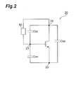
- FIG. 2 is a diagram for explaining the relationship between the parasitic capacitance existing in the semiconductor switch element and the capacitance suppression element section.
- parasitic capacitances C GS , C GD , and C DS exist between the respective terminals of the semiconductor switch element 20.
- the parasitic capacitances C GS , C GD , and C DS are shown as capacitance elements.
- At least one capacitance suppression element section 50 is connected to the semiconductor switch element 20 so as to suppress at least one of the parasitic capacitances C GS , C GD , and C DS .
- the capacitance suppression element section 50 is connected between the terminals where the parasitic capacitance C GS , C GD , or C DS to be suppressed exists.
- the capacitance suppression element section 50 is connected in parallel with the parasitic capacitance C GS , C GD , or C DS to be suppressed.
- FIG. 2 shows one example in which the capacitance suppression element section 50 is connected between the gate terminal 21 and the drain terminal 22 to suppress the parasitic capacitance C GD .
- the parasitic capacitance to be suppressed by the capacitance suppression element section 50 out of the parasitic capacitances C GS , C GD , and C DS is referred to as parasitic capacitance C X .
- the capacitance suppression element section 50 suppresses the parasitic capacitance C X of the semiconductor switch element 20 at a frequency N times as high as the clock frequency of the PWM signal.
- the capacitance suppression element section 50 is configured to satisfy following conditions.
- a reactance of the capacitance suppression element section 50 is X( ⁇ ) as a function of an angular frequency ⁇
- the above (i) is expressed by an expression (5)
- the above (ii) is expressed by an expression (6). That is, the capacitance suppression element section 50 is configured to satisfy the expressions (5) and (6).
- X( ⁇ ) is also referred to as reactance curve of the capacitance suppression element section 50.
- j represents an imaginary unit
- ⁇ 0 represents a product of the clock frequency f CLK of the PWM signal and 2 ⁇
- ⁇ M represents a product of the modulation frequency f M of the PWM signal and 2 ⁇
- C X represents the parasitic capacitance between the terminals of the semiconductor switch element 20 where the capacitance suppression element section 50 is connected.
- C X C GD .
- R CO represents the output impedance of the drive circuit 30 connected to the gate terminal 21 of the semiconductor switch element 20.
- ⁇ may be sufficiently greater than 1.
- ⁇ may be 10 or more, or may be 100 or more.
- the capacitance suppression element section 50 When the capacitance suppression element section 50 is connected between the terminals where the parasitic capacitance C X to be cancelled exists out of the parasitic capacitances C GS , C GD , and C DS between the terminals of the semiconductor switch element 20, the capacitance suppression element section 50 is connected in parallel with the parasitic capacitance C X .
- the capacitance suppression element section 50 satisfies the expressions (5) and (6), a combined impedance of the capacitance suppression element section 50 and the parasitic capacitance C X in parallel therewith has a very high value (e.g., an infinity ⁇ ) at the N-th order harmonic of the clock frequency f CLK of the PWM signal.
- the semiconductor switch element 20 to which the capacitance suppression element section 50 satisfying the expression (5) is connected can operate as in a case in which the parasitic capacitance C X between the terminals where the capacitance suppression element section 50 is connected practically does not exist. That is, the capacitance suppression element section 50 can reduce the parasitic capacitance C X of the semiconductor switch element 20 in the operation of the semiconductor switch element 20.
- FIG. 3 is a diagram showing the relationship between a reactance curve of the capacitance suppression element section and a reactance curve of the parasitic capacitance, and corresponds to the relationship of the expression (5).
- a horizontal axis represents an angular frequency ⁇
- a vertical axis represents a reactance [ ⁇ ].
- a solid line in FIG. 3 represents the reactance curve X( ⁇ ) of the capacitance suppression element section 50.
- An dashed dotted line in FIG. 3 represents the reactance curve (1/ ⁇ C X ) of the parasitic capacitance.
- the reactance curve of the parasitic capacitance C X is a curve representing an absolute value of a reactance of the parasitic capacitance C X
- the reactance function X( ⁇ ) of the capacitance suppression element section 50 having the minimum number of elements constituting the capacitance suppression element section 50 can satisfy an expression (7).
- jX ⁇ ⁇ ⁇ - ⁇ 2 + ⁇ z ⁇ 0 2 ⁇ - ⁇ 2 + ⁇ z ⁇ 1 2 ⁇ - ⁇ 2 + ⁇ zN - 1 2 j ⁇ ⁇ - ⁇ 2 + ⁇ p ⁇ 1 2 ⁇ - ⁇ 2 + ⁇ pN - 1 2
- ⁇ pt , ⁇ z0 , and ( Dzt are values determined so as to satisfy 0 ⁇ z0 ⁇ 0 , and t ⁇ 0 ⁇ pt ⁇ zt ⁇ (t+1) ⁇ 0 , and also satisfy the expressions (5) and (6), and ⁇ is any value determined so as to satisfy the expressions (5) and (6).
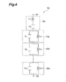
- FIG. 4 is a diagram illustrating one example of the circuit configuration of the capacitance suppression element section 50 that satisfies the expression (7).
- the capacitance suppression element section 50 has N circuit sections of first to N-th circuit sections 53 1 to 53 N connected in series between terminals 51 and 52 of the capacitance suppression element section 50.
- the first circuit section 53 1 is obtained by connecting a capacitance element C 0 and an inductance element L 0 in series.
- the first circuit section 53 1 is a series circuit.
- the capacitance suppression element section 50 may be composed only of the first circuit section 53 1 .
- an i-th circuit section 53 i (i is an integer of 2 to N) out of the second to N-th circuit sections 53 2 to 53 N is obtained by connecting a capacitance element C i-1 and an inductance element L i-1 in parallel.
- the i-th circuit section 53 i constitutes a parallel resonant circuit.
- the circuit configuration shown in FIG. 4 is also referred to as basic configuration for the purpose of description. In the basic configuration, the parasitic capacitance can be reduced with respect to another harmonic by increasing the parallel resonant circuit by one stage as shown in FIG. 4 .
- the parasitic capacitance when the parasitic capacitance can be reduced with respect to the N-th order harmonic, the parasitic capacitance can be also reduced with respect to any harmonic other than the N-th order harmonic by increasing the number of stages of the parallel resonant circuit. It is not necessary to reduce the parasitic capacitance sequentially from a lowest order harmonic. It is also not necessary to reduce the parasitic capacitance only with respect to a next-order harmonic. For example, the parasitic capacitance may be reduced with respect to harmonics of every two orders such as odd orders of 1, 3, 5, 7 and so on.
- the expression (5) is expressed as expressions (8 0 ) to (8 N-1 ).
- the expression (7) can be transformed into an expression (9).
- jX ⁇ j ⁇ ⁇ L 0 + 1 j ⁇ ⁇ C 0 + 1 C 1 ⁇ j ⁇ ⁇ 0 - ⁇ 0 2 + ⁇ p ⁇ 1 2 + 1 C 2 ⁇ j ⁇ ⁇ 0 - ⁇ 0 2 + ⁇ p ⁇ 2 2 + ... + 1 C N - 1 ⁇ j ⁇ ⁇ 0 - ⁇ 0 2 + ⁇ pN - 1 2
- L 1 1/(C 1 /( ⁇ p1 ) 2
- L 2 1/(C 2 ( ⁇ p2 ) 2
- ...
- L N-1 1/(C N-1 ( ⁇ p(N-1) ) 2 ).
- ⁇ p1 to ⁇ p(N-1) is given within a range of 0 ⁇ z0 ⁇ 0 , and t ⁇ 0 ⁇ pt ⁇ zt ⁇ (t+1) ⁇ 0 (t is an integer of 1 to N-1).
- t is an integer of 1 to N-1).
- L 0 , C 0 , L 1 , C 1 , L 2 , and C 2 are as follows.
- ⁇ , ⁇ z0 , and ⁇ z1 can be also obtained.
- One example of a method for obtaining ⁇ , ⁇ z0 , and ⁇ z1 will be described.
- ⁇ , ⁇ z0 , ⁇ z1 , and ⁇ z2 can be obtained based on the expressions (15a) to (15d) and the calculated L 0 , C 0 , L 1 , C 1 , L 2 , and C 2 .
- FIG. 4 one example of the element configuration of the capacitance suppression element section 50 has been described by reference to FIG. 4 .
- the configuration of the capacitance suppression element section 50 is not limited to that in FIG. 4 .
- C 0 , C 1 , C 2 , L 0 , L 1 , and L 2 are assigned to capacitance elements and inductance elements in a similar manner to the case in FIG. 4 .
- Element values of the elements are determined so as to satisfy the expressions (5) and (6).
- the capacitance suppression element section 50 includes six reactance elements.
- the capacitance suppression element section 50 includes at least six reactance elements.
- the expression (16) may also include the circuit configuration in FIG. 6(a) .
- an expression corresponding to the element configuration in FIG. 6(a) is as in an expression (18).
- C 0 , C 1 , C 2 , L 0 , L 1 , and L 2 are assigned to the capacitance elements and the inductance elements in FIG. 6(a) in a similar manner to the case in FIG. 4 .
- C 0 , C 1 , C 2 , L 0 , L 1 , and L 2 are represented as C 0a , C 1a , C 2a , L 0a , L 1a , and L 2a so as to be distinguished from the case in FIG. 4 .
- X s s ⁇ L 0 ⁇ a + 1 s ⁇ C 0 ⁇ a + 1 s ⁇ L 1 ⁇ a + 1 s ⁇ C 1 ⁇ a + 1 s ⁇ L 2 ⁇ a + 1 s ⁇ C 2 ⁇ a + 1 s ⁇ C 2 ⁇ a
- expressions (20a) to (20f), expressions (21a) to (21g), and expressions (22a) to (22d) can be obtained.
- the element values of the respective elements in the case of the circuit configuration shown in FIG. 6(a) that is, L 0a , C 0a , L 1a , C 1a , L 2a , and C 2a can be obtained.
- a 3 , a 2 , a 1 , a 0 , b 2 , b 1 , and bo are obtained by the expressions (17a) to (17g).
- the element values of the elements of other circuit configurations such as the respective circuit configurations shown in FIGS. 5(a) to 5(c) may be similarly obtained. That is, the expression (11) is transformed so as to represent the characteristics of the respective circuit configurations.
- the element values of the respective circuit configurations can be obtained by using a 3 , a 2 , a 1 , a 0 , b 2 , and b 1 , obtained by comparison of rational function coefficients before and after the expression transformation.
- the element values may be also determined by using a numerical analytical method.
- the respective element values of the capacitance suppression element section 50 are determined by assuming the circuit configuration as shown in FIG. 4 or the like.
- the circuit configuration of the capacitance suppression element section 50 may be designed so as to satisfy the expressions (5) and (6).
- the circuit configuration may be determined by a topology search method, for example.
- One example of a method for determining the circuit configuration by the topology search method is as follows.
- n (p 2 ) n +a n-1 (p 2 ) n-1 +...+a 0 is defined as D n .
- p 1/s.
- arrows indicate the direction of expression transformation.
- the rule 5 indicates that s and 1/p can be mutually converted to each other.
- the right-hand side of the expression (28) can be transformed as follows by applying the rules 1 to 4 a plurality of times.
- [Expression 29] D 3 s ⁇ D 2 ⁇ s ⁇ D 0 + D 2 s ⁇ D 2 ⁇ s + D 0 s ⁇ D 0 + s ⁇ D 1 D 2 ⁇ s + 1 s + s ⁇ D 0 D 1 + s ⁇ D 0 D 1 ⁇ s + 1 s + 1 D 1 s ⁇ D 0 + 1 D 1 s ⁇ D 0 + 1 D 1 s ⁇ D 0 + 1 D 1 s ⁇ D 0 ⁇ s + 1 s + 1 s + 1 s + 1 s + 1 s + 1 s + 1 s + 1 s + 1 s + 1 s + 1 s + 1 s + 1 s + 1 s + 1 s + 1 s + 1 s + 1 s + 1 s + 1 s + 1 s
- the number of elements of the capacitance suppression element section 50 is determined by the order of the harmonic to be suppressed, i.e., the value of N.
- the number of capacitance elements and the number of inductance elements are equal to each other.
- the capacitance elements and the inductance elements may be arranged according to following rules.
- the circuit configuration of the capacitance suppression element section 50 can be determined more quickly by applying the above rules A to F.
- the capacitance suppression element section 50 is connected to the semiconductor switch element 20.
- the capacitance suppression element section 50 is designed so as to satisfy the expressions (5) and (6) as described above. It is thus considered that the parasitic capacitance C X practically does not exist between the terminals of the semiconductor switch element 20 where the capacitance suppression element section 50 is connected up to the N-th order harmonic of the clock frequency f CLK of the PWM signal. That is, the parasitic capacitance C X is neutralized by the capacitance suppression element section 50. A time required to charge and discharge the parasitic capacitance C X can be thereby reduced, so that switching is performed at higher speed in the semiconductor switch element 20. As a result, the switching speed of the switching circuit 10 can be increased, and the power efficiency of the switching circuit 10 can be improved.
- the capacitance suppression element section 50a is connected between the gate terminal 21 a and the drain terminal 22a of the semiconductor switch element 20a.
- the parasitic capacitance C GD of the semiconductor switch element 20a can be cancelled.
- the parasitic capacitance C GD of the semiconductor switch element 20b can be cancelled by the capacitance suppression element section 50b.
- Overdrive may be performed as a method for increasing the switching speed of the switching circuit 10 using the semiconductor switch element 20.
- the configuration of the drive circuit 30 may become complicated so as to perform the overdrive as compared to a case in which the overdrive is not performed.
- the drive circuit 30 also needs to have a higher ampacity so as to perform the overdrive. Accordingly, the drive circuit 30 may be increased in size, or the power efficiency of the switching circuit 10 including the drive circuit 30 may be reduced as compared to the case in which the overdrive is not performed. In this case, even when the high-speed switching is achieved by the overdrive, an improvement in the power efficiency by the high-speed switching itself may not be obtained.
- the capacitance suppression element section 50 neutralizes the parasitic capacitance C X itself to achieve the high-speed switching. Accordingly, the switching speed of the switching circuit 10 can be increased and the power efficiency can be improved as described above without performing the overdrive.
- the capacitance suppression element section 50 can achieve the state in which the parasitic capacitance C X practically does not exist in the present embodiment, the capacitance suppression element section 50 only needs to reduce the influence of the parasitic capacitance C X when the capacitance suppression element section 50 is connected.
- the circuit configuration of the capacitance suppression element section 50 and the element values of the elements of the capacitance suppression element section 50 may be set to values with which an equivalent capacitance of the terminal value where the capacitance suppression element section 50 is connected becomes 1/10 or less of the original parasitic capacitance C X by connecting the capacitance suppression element section 50.
- the element values of the elements of the capacitance suppression element section 50 may be also set to values with which the equivalent capacitance becomes half or less of the original parasitic capacitance C X .
- the switching circuit 10 includes the inductance element L L as the inductive load as one example in the present embodiment.
- the switching circuit 10 can be used for an inverter or the like.
- the switching circuit 10 can be used for driving the motor.
- FIG. 9 is a diagram illustrating a model of a semiconductor switch element for simulations.
- a MOS field-effect transistor was assumed to be used as the semiconductor switch element 20. It was assumed that parasitic resistances R G and R I existed in addition to the parasitic capacitances C GS , C DS , and C GD in the semiconductor switch element 20.
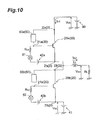
- FIG. 10 is a circuit diagram for simulations corresponding to the switching circuit 10 shown in FIG. 1 .
- elements corresponding to those in FIG. 1 are assigned the same reference numerals for the convenience of description.
- the first drive circuit section 31 and the second drive circuit section 32 of the drive circuit 30 shown in FIG. 1 are shown as signal sources 61 and 62 respectively corresponding to the semiconductor switch elements 20a and 20b.
- the semiconductor switch elements 20a and 20b respectively have the configuration shown in FIG. 9 .
- Element values or the like in a simulation circuit model shown in FIG. 10 were set as follows.
- Clock frequency f CLK of the PWM signal supplied from the signal sources 61 and 62 120 kHz
- Modulation frequency f M of the PWM signal supplied from the signal sources 61 and 62 60 kHz
- the basic configuration shown in FIG. 4 was employed for the capacitance suppression element sections 50a and 50b.
- the power efficiency was calculated by (output voltage V out ⁇ output current I out )/(supply voltage V DD ⁇ supply current I EE ) ⁇ 100(%).
- the output current I out is a current flowing through the inductance L L .
- the supply current I EE is a current flowing into the drain terminal 22a.
- the power efficiency in this case was 96%.
- the power efficiency in this case was 89%.
- simulations 2a to 2c were performed such that the parasitic capacitance C GD was suppressed by use of the capacitance suppression element section 50 by setting the values of the parasitic capacitances C GD , C GS , and C DS of the semiconductor switch element 20 to the values indicated as the device parameters above.
- a simulation 2d was also performed for comparison as a case in which the capacitance suppression element section 50 was not connected.
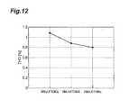
- Total harmonic distortion (THD) was also calculated so as to examine the influence of the capacitance suppression element section on the THD.
- the simulation was performed for the case in which the capacitance suppression element section 50 was not connected, and power efficiency and time ratio were calculated.
- FIG. 11 is a diagram showing the calculation results of the power efficiency and the time ratio in the simulations 2a to 2d.
- a horizontal axis represents the performed simulations.
- a vertical axis represents the power efficiency (%) and the time ratio (%).
- FIG. 12 is a diagram showing the calculation results of the THD in the simulations 2a, 2b, and 2c.
- a horizontal axis represents the performed simulations.
- a vertical axis represents the total harmonic distortion: THD (%).
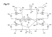
- FIG. 13 is a circuit diagram illustrating the schematic configuration of a switching circuit according to a second embodiment of the present invention.
- a switching circuit 70 is a differential switching circuit.
- the switching circuit 70 includes four semiconductor switch elements 20a, 20b, 20c, and 20d. All the semiconductor switch elements 20a to 20d are the same semiconductor switch element as that of the first embodiment. In the following description, the semiconductor switch elements 20a to 20d may be sometimes referred to as semiconductor switch element 20 in a similar manner to the case of the first embodiment.
- the switching circuit 70 may include drive circuits 30a, 30b, 30c, and 30d that respectively supply PWM signals to gate terminals 21a, 21b, 21c, and 21d of the semiconductor switch elements 20a, 20b, 20c, and 20d. Although the drive circuits 30a, 30b, 30c, and 30d are respectively connected to the four semiconductor switch elements 20a, 20b, 20c, and 20d in FIG. 11 , only one drive circuit 30 may be employed as in the case of the first embodiment.
- the drive circuit 30a and the drive circuit 30b correspond to the first drive circuit section 31 and the second drive circuit section 32.
- a drain terminal (an output terminal) 22a of the semiconductor switch element (a first semiconductor switch element) 20a and a drain terminal (an output terminal) 22c of the semiconductor switch element (a third semiconductor switch element) 20c are connected to each other.
- a source terminal (a common terminal) 23b of the semiconductor switch element (a second semiconductor switch element) 20b and a source terminal (a common terminal) 23d of the semiconductor switch element (a fourth semiconductor switch element) 20d are connected to each other.
- a first power source 40 and a second power source 41 are respectively connected to a connection point between the drain terminal 22a and the drain terminal 22c, and a connection point between the source terminal 23b and the source terminal 23d.
- the first power source 40 supplies a positive voltage V DD to the drain terminals 22a and 22c.
- the second power source 41 supplies a negative voltage V SS to the source terminals 23b and 23d.
- the semiconductor switch elements 20a and 20b are connected in series in a similar manner to the first embodiment.
- the semiconductor switch elements 20c and 20d are also connected in series. That is, a source terminal 23c of the semiconductor switch element 20c and a drain terminal 22d of the semiconductor switch element 20d are connected to each other.
- a connection point between a source terminal 23a and a drain terminal 22b, and a connection point between the source terminal 23c and the drain terminal 22d are connected via a load 80.
- the load 80 may be an inductive load such as an inductance element in a similar manner to the first embodiment, or may be a resistive load. For example, when a motor is connected as the load 80, the motor may be driven.
- the drive circuits 30a and 30d respectively supply positive-phase PWM signals to the gate terminals 21a and 21d of the semiconductor switch elements 20a and 20d.
- the drive circuits 30b and 30c respectively supply negative-phase PWM signals to the gate terminals 21b and 21c of the semiconductor switch elements 20b and 20c.
- the PWM signals supplied to the gate terminals 21 a to 21d have the same clock frequency f CLK .
- Resistances R CO between the respective semiconductor switch elements 20a to 20d and the corresponding drive circuits 30a to 30d represent output impedances of the drive circuits 30a to 30d respectively connected to the gate terminals 21 a to 21 d of the semiconductor switch elements 20a to 20d.
- Third power sources 42a to 42d are respectively connected between the source terminals 23a to 23d of the semiconductor switch elements 20a to 20d and the drive circuits 30a to 30d. Positive poles of the third power sources 42a to 42d are connected to the corresponding source terminals 23a to 23d. Negative poles of the third power sources 42a to 42d are connected to the corresponding drive circuits 30a to 30d. Accordingly, predetermined negative voltages based on the source terminals 23a to 23d are supplied to the drive circuits 30a to 30d in a similar manner to the first embodiment. The magnitude of the predetermined negative voltage may be equal to that of the negative voltage supplied from the third power source 42a or 42b in the first embodiment.
- the drive circuits 30a and 30d supply the positive-phase PWM signals to the semiconductor switch elements 20a and 20d
- the drive circuits 30b and 30c supply the negative-phase PWM signals to the semiconductor switch elements 20b and 20c.
- the semiconductor switch elements 20a and 20d are in an ON state
- the semiconductor switch elements 20b and 20c are in an OFF state.
- a current flows in the direction of an arrow B1 in FIG. 13 .
- the semiconductor switch elements 20a and 20d are in the OFF state
- the semiconductor switch elements 20b and 20c are in the ON state.
- a current flows in the direction of an arrow B2 in FIG. 13 . Accordingly, the direction of a current flowing through the load 80 can be switched according to the PWM signals.
- capacitance suppression element sections 50a and 50c are connected, at least one by one, to the semiconductor switch elements 20a and 20c so as to suppress at least one of three parasitic capacitances C GS , C GD , and C DS of the semiconductor switch elements 20a and 20c.
- the capacitance suppression element sections 50a and 50c are respectively connected between the terminals where a parasitic capacitance C X to be suppressed exists.
- FIG. 13 shows a configuration in which the capacitance suppression element sections 50a and 50c are respectively connected between the gate terminals 21a and 21 c and the drain terminals 22a and 22c of the semiconductor switch elements 20a and 20c.
- the capacitance suppression element sections 50a and 50c have the same circuit configuration as that of the first embodiment, the description thereof is omitted.
- the capacitance suppression element sections 50a and 50c may be sometimes referred to as capacitance suppression element section 50 in a similar manner to the case of the first embodiment.
- capacitance elements 90 and 91 are further respectively connected between the drain terminal 22b of the semiconductor switch element 20b and the gate terminal 21d of the semiconductor switch element 20d, and between the gate terminal 21b of the semiconductor switch element 20b and the drain terminal 22d of the semiconductor switch element 20d.
- a capacitance C 90 of the capacitance element (a first capacitance element) 90 is substantially equal to the parasitic capacitance C GD between the gate terminal 21d and the drain terminal 22d of the semiconductor switch element 20d at an N-th order harmonic of the PWM signal.
- a capacitance C 91 of the capacitance element (a second capacitance element) 91 is substantially equal to the parasitic capacitance C GD between the gate terminal 21b and the drain terminal 22b of the semiconductor switch element 20b.
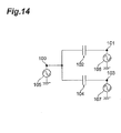
- FIG. 14 is a diagram for explaining the principle that the parasitic capacitance of the semiconductor switch element can be suppressed by connecting the capacitance element.
- FIG. 14 is a model diagram for calculating a capacitance component anticipated from the gate terminal 21d in the semiconductor switch element 20d having a differential circuit.
- a capacitance element 102 is connected between a first terminal 100 and a second terminal 101, and a capacitance element 104 having the same capacitance as that of the capacitance element 102 is connected between the first terminal 100 and a third terminal 103.
- the capacitance element 102 represents the parasitic capacitance C GD
- the capacitance element 104 corresponds to the capacitance element 90.
- a signal source 105 is connected to the first terminal 100, and voltage sources 106 and 107 are respectively connected to the second terminal 101 and the third terminal 103.
- the first terminal 100 corresponds to the gate terminal 21d of the semiconductor switch element 20d.
- the signal source 105 supplies a gate voltage V X to the first terminal 100 so as to represent the input of the PWM signal into the gate terminal 21d.
- the second terminal 101 corresponds to the drain terminal 22d of the semiconductor switch element 20d.
- the voltage source 106 supplies a voltage V D to the second terminal 101 so as to represent the voltage of the drain terminal 22d.
- the third terminal 103 corresponds to the drain terminal 22b of the semiconductor switch element 20b. It is assumed that a drain potential of the drain terminal 22b of the semiconductor switch element 20b is opposite to a drain potential of the drain terminal 22d of the semiconductor switch element 20d. Thus, a drain voltage (-V D ) is supplied to the third terminal 103 from the voltage source 107.
- the parasitic capacitance C GD between the gate and the drain equivalently does not exist, and it appears that a capacitance having the value of 2C GD exists between the gate terminal 21d and the ground (that is, the source terminal).
- the influence of the parasitic capacitance C GD of the semiconductor switch element 20d can be neutralized or cancelled.
- the semiconductor switch element 20d has been mainly described here, the same applies to the semiconductor switch element 20b. That is, when the capacitance element 91 is provided as shown in FIG. 13 , the influence of the parasitic capacitance C GD of the semiconductor switch element 20b can be neutralized or cancelled at the N-th order harmonic of the PWM signal.
- the parasitic capacitance C GD between the gate and the drain affects the switching speed the most in the semiconductor switch elements 20a to 20d.
- the switching speeds of the semiconductor switch elements 20b and 20d can be increased.
- the capacitance elements 90 and 91 neutralize the influence of the parasitic capacitance C GD
- the capacitance elements 90 and 91 only need to reduce or suppress the influence of the parasitic capacitance C GD .
- the capacitances of the capacitance elements 90 and 91 may be set to values with which an equivalent capacitance becomes 1/10 or less of the original parasitic capacitance C X by connecting the capacitance elements 90 and 91 as described in the first embodiment.
- the capacitances of the capacitance elements 90 and 91 may be also set to values with which the equivalent capacitance becomes half or less of the original parasitic capacitance C X .
- the capacitance suppression element sections 50a and 50c reduce the influence of the parasitic capacitance C GD with respect to the semiconductor switch elements 20a and 20c.
- the capacitance elements 90 and 91 reduce the influence of the parasitic capacitance C GD with respect to the semiconductor switch elements 20b and 20d.
- the switching speeds of the semiconductor switch elements 20a to 20d can be increased, and the power efficiency can be improved in a similar manner to the case of the first embodiment. Since the influence of the parasitic capacitance C GD is reduced by using the capacitance suppression element sections 50a and 50c, and the capacitance elements 90 and 91, the switching speed and the power efficiency can be improved without performing overdrive in a similar manner to the case of the first embodiment.
- the switching circuit 70 can be more easily designed. Accordingly, the configuration of the switching circuit 70 is more effectively employed when there is a difference in device parameters of the semiconductor switch elements 20a to 20d.
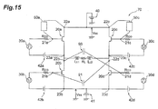
- FIG. 15 is a model for simulations corresponding to the switching circuit 70 shown in FIG. 13 .
- the load 80 is represented by a series circuit of an inductance element L L1 , a resistance R L , and an inductance element L L2 .
- a voltage to the ground of the connection point between the source terminal 23a of the semiconductor switch element 20a and the drain terminal 22b of the semiconductor switch element 20b was set as an output voltage V out .
- the semiconductor switch elements 20a to 20d had the configuration shown in FIG. 9 in a similar manner to the first embodiment.
- the device parameters of the semiconductor switch elements 20a to 20d were the same as the device parameters described in the first embodiment.
- the capacitance elements 90 and 91 had a capacitance of 63 pF similarly to the capacitance C GD .
- Element values or the like in the simulation circuit model shown in FIG. 15 were set as follows.
- Modulation frequency f M of the PWM signal supplied from the drive circuits 30a to 30d 60 kHz
- Negative voltage V SS supplied to the source terminals 23b and 23d -400 V
- the simulation was performed by assuming a case in which none of the capacitance elements 90 and 91 and the capacitance suppression element sections 50a and 50c was connected. In the simulation, all the parasitic capacitances of each of the semiconductor switch elements 20a to 20d were set to the values indicated as the device parameters.
- the simulation was performed by assuming a case in which the parasitic capacitance C GD between the gate and the drain of each of the semiconductor switch elements 20 was cancelled by the capacitance elements 90 and 91 and the capacitance suppression element sections 50a and 50c.
- the parasitic capacitance C GD of each of the semiconductor switch elements 20a to 20d was set to 0 as an ideal state.
- the simulation was performed by assuming that the parasitic capacitances C GD of the semiconductor switch elements 20a to 20d were neutralized by the capacitance suppression element sections 50 without providing the capacitance elements 90 and 91.
- the parasitic capacitance C GD was set to 0.
- the simulation was performed on the same conditions as the simulation 3 except that the capacitance elements 90 and 91 were connected.
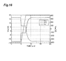
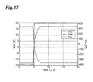
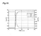
- FIGS. 16 to 19 are diagrams respectively showing the results of the simulations 3 to 6.
- FIGS. 16 to 19 show changes in voltages V GS1a and V GS2a between the gate and the source of the semiconductor switch element 20 and the output voltage V out with respect to time.
- a horizontal axis represents the time [ ⁇ s]
- a vertical axis represents the voltages V GS [V] between the gate and the source and the output voltage V out [V].
- FIGS. 16 to 19 show V GSa as V GS in the semiconductor switch element 20a at an upper left position in FIG. 15
- V GSb as V GS in the semiconductor switch element 20b at a lower left position in FIG. 15
- the output voltage V out as the voltage to the ground of the connection point between the semiconductor switch element 20a and the semiconductor switch element 20b.
- FIGS. 16 , 17 , and 18 it can be understood that there is a more rapid voltage change, particularly, a more rapid change in the output voltage V out than that in the case shown in FIG. 16 by providing the capacitance suppression element sections 50a and 50c and thereby cancelling the parasitic capacitances C GD of the semiconductor switch elements 20a and 20c, so that the results shown in FIG. 18 approaches to an ideal state shown in FIG. 17 .
- FIGS. 17 , 18 , and 19 it can be understood that there is a still more rapid voltage change, particularly, a still more rapid change in the output voltage V out than that in the case shown in FIG. 18 by providing the capacitance suppression element sections 50 and also connecting the capacitance elements, so that the results shown in FIG. 19 approaches to an ideal state shown in FIG. 17 .
- the capacitance suppression element section may be also used to reduce the parasitic capacitance with respect to the semiconductor switch elements 20b and 20d instead of the capacitance elements 90 and 91.
- the influence of the capacitance having the value of 2C GD as the capacitance between the gate terminals 21d and 21b and the grounds (the source terminals) appearing to equivalently exist by the capacitance elements 90 and 91 may be substantially reduced by further connecting the capacitance suppression element section.
- At least one of the parasitic capacitances C X of the semiconductor switch elements 20b and 20d may be reduced by combination of the capacitance suppression element section and the capacitance elements 90 and 91.
- the semiconductor switch element of the switching circuit is not limited to the MOS field-effect transistor described above.
- the semiconductor switch element may be an insulated gate bipolar transistor, a junction field-effect transistor, or a junction bipolar transistor.
- the semiconductor switch element may be a thyristor.
- the semiconductor switch element is the insulated gate bipolar transistor or the junction bipolar transistor, the semiconductor switch element has a gate terminal as the input terminal, a collector terminal as the output terminal, and an emitter terminal as the common terminal.
- the semiconductor switch element When the semiconductor switch element is the junction field-effect transistor, the semiconductor switch element has a gate terminal as the input terminal, a drain terminal as the output terminal, and a source terminal as the common terminal in a similar manner to the case of the MOS field-effect transistor.
- the semiconductor switch element When the semiconductor switch element is the thyristor, the semiconductor switch element has a gate terminal as the input terminal, an anode terminal as the output terminal, and a cathode terminal as the common terminal.
- the plurality of semiconductor switch elements of the switching circuit may have different configurations.
- the capacitance suppression element sections respectively connected to the plurality of semiconductor switch elements may also have different configurations.
- the number of semiconductor switch elements of the switching circuit is also not limited to 2 or 4 described above.
- the switching circuit only needs to have at least one semiconductor switch element.
- pulse-like signal supplied to the semiconductor switch element is the PWM signal in the various embodiments described above, any pulse-like signal may be employed as long as the ON/OFF switching of the semiconductor switch element can be controlled.
Landscapes
- Electronic Switches (AREA)
- Power Conversion In General (AREA)
- Semiconductor Integrated Circuits (AREA)
Abstract
Description
- The present invention relates to a switching circuit.
- There are known switching circuits using semiconductor switch elements such as transistors (See Patent Literature 1). Since parasitic capacitance exists in the semiconductor switch element due to its configuration, a charge and discharge time of the parasitic capacitance is required when the semiconductor switch performs a switching operation. As a method for reducing the charge and discharge time of the parasitic capacitance, the semiconductor switch element is overdriven in
Patent Literature 1. - [Patent Literature 1] Japanese Utility Model Publication No.
Hei-07-47993 - In the overdrive, however, it is necessary to supply more voltage (or more current) than is required to drive the semiconductor switch element. Thus, the semiconductor switch element may be damaged in some cases, and the power efficiency of the switching circuit is easily reduced.
- It is an object of the present invention to provide a switching circuit which can increase a switching speed and can also improve power efficiency without performing overdrive.
- A switching circuit according to one aspect of the present invention is a switching circuit including at least one semiconductor switch element having an input terminal, an output terminal, and a common terminal, a pulse-like signal being applied between the input terminal and the common terminal to switch a current between the output terminal and the common terminal. The switching circuit further includes a capacitance suppression element section connected at least one of between the input terminal and the output terminal, between the input terminal and the common terminal, and between the output terminal and the common terminal. The capacitance suppression element section reduces a parasitic capacitance between the terminals of the semiconductor switch element, where the capacitance suppression element section is connected, to less than that obtained when the capacitance suppression element section is not connected, at a frequency N times (N is an integer of 1 or more) as high as a clock frequency of the pulse-like signal.
- A switching circuit according to another aspect of the present invention is a switching circuit including four semiconductor switch elements each having an input terminal, an output terminal, and a common terminal, an output terminal of a first semiconductor switch element out of the four semiconductor switch elements and an output terminal of a third semiconductor switch element out of the four semiconductor switch elements being connected to each other, a common terminal of a second semiconductor switch element out of the four semiconductor switch elements and a common terminal of a fourth semiconductor switch element out of the four semiconductor switch elements being connected to each other, a common terminal of the first semiconductor switch element and an output terminal of the second semiconductor switch element being connected to each other, a common terminal of the third semiconductor switch element and an output terminal of the fourth semiconductor switch element being connected to each other, and a pulse-like signal being applied to each input terminal of the first to fourth semiconductor switch elements such that the second and third semiconductor switch elements are in an OFF state when the first and fourth semiconductor switch elements are in an ON state and the second and third semiconductor switch elements are in an ON state when the first and fourth semiconductor switch elements are in an OFF state. The switching circuit further includes a capacitance suppression element section connected at least one of between the input terminal and the output terminal, between the input terminal and the common terminal, and between the output terminal and the common terminal of at least one of the four semiconductor switch elements. The capacitance suppression element section reduces a parasitic capacitance between the terminals of the semiconductor switch element, where the capacitance suppression element section is connected, to less than that obtained when the capacitance suppression element section is not connected, at a frequency N times (N is an integer of 1 or more) as high as a clock frequency of the pulse-like signal.
- In the configuration of the switching circuit according to the one aspect and the another aspect of the present invention, the influence of the parasitic capacitance itself existing in the semiconductor switch element is reduced by the capacitance suppression element section. Accordingly, a switching speed can be increased, and power efficiency can be improved without performing overdrive.
- The switching circuit according to the another aspect of the present invention may further include a first capacitance element connected between the output terminal of the second semiconductor switch element and the input terminal of the fourth semiconductor switch element, and a second capacitance element connected between the input terminal of the second semiconductor switch element and the output terminal of the fourth semiconductor switch element. In the aspect, the first capacitance element may have a capacitance to reduce a parasitic capacitance between the input terminal and the output terminal of the fourth semiconductor switch element to less than that obtained when the first capacitance element is not connected at a frequency N times (N is an integer of 1 or more) as high as the clock frequency of the pulse-like signal supplied to the fourth semiconductor switch element. The second capacitance element may have a capacitance to reduce a parasitic capacitance between the input terminal and the output terminal of the second semiconductor switch element to less than that obtained when the second capacitance element is not connected at a frequency N times (N is an integer of 1 or more) as high as the clock frequency of the pulse-like signal supplied to the second semiconductor switch element.
- In the configuration, since the first and second capacitance elements are connected, the parasitic capacitance between the input terminal and the output terminal of each of the second and fourth semiconductor switch elements can be reduced. As a result, the switching speed can be further increased and the power efficiency can be further improved.
- The pulse-like signal may be a PWM signal. In this case, the capacitance suppression element section may be configured to satisfy expressions (1) and (2) when a reactance of the capacitance suppression element section is a function X(ω) of an angular frequency.
[Expression 1]
[Expression 2]
- (In the expressions (1) and (2), j represents an imaginary unit, ω0 represents a product of a clock frequency of the PWM signal and 2π, ωM represents a product of a modulation frequency of the PWM signal and 2π, CX represents a parasitic capacitance between the terminals of the semiconductor switch element as the parasitic capacitance between the terminals of the semiconductor switch element where the capacitance suppression element section is connected, Rco represents an output impedance of a drive circuit that is connected to the input terminal of the semiconductor switch element where the capacitance suppression element section is connected and supplies the PWM signal.)
- In the configuration, a combined impedance of the parasitic capacitance between the terminals where the capacitance suppression element section is connected and the capacitance suppression element section becomes very large in the semiconductor switch element where the capacitance suppression element section is connected. As a result, the semiconductor switch element approaches a state in which the parasitic capacitance between the terminals where the capacitance suppression element section is connected practically does not exist. The influence of the parasitic capacitance can be thereby reduced.
- The function X(ω) may be expressed by an expression (3).
[Expression 3]
- (In the expression (3), when t is an integer of 1 to N-1, ωz0 is a value that satisfies 0<ωz0<ω0, ωzt and ωpt are values that satisfy tω0<ωpt<ωzt<(t+1)ω0, and β is any value.)
- The capacitance suppression element section may be connected between the input terminal and the output terminal of the semiconductor switch element. In this case, the parasitic capacitance of the semiconductor switch element as the parasitic capacitance between the input terminal and the output terminal can be reduced by the capacitance suppression element section.
- N may be 2 or more. In this case, the capacitance suppression element section may have first to N-th circuit sections connected in series. Moreover, the first circuit section may be composed of an inductance element and a capacitance element connected in series, and an i-th circuit section (i is an integer of 2 to N) out of the second to N-th circuit sections may be composed of an inductance element and a capacitance element connected in parallel.
- In this case, the number of elements constituting the capacitance suppression element section that can reduce the parasitic capacitance up to an N-th order harmonic can be minimized.
- When element values of the inductance element and the capacitance element of the first circuit section are respectively L0 and C0, and element values of the inductance element and the capacitance element of the i-th circuit section are respectively Li-1 and Ci-1, the element values of the inductance element and the capacitance element of the first circuit section and an element value of a capacitance element of each of the second to N-th circuit sections may satisfy an expression (4), and Li-1 maybe 1/(Ci-1(ωp(i-1))2).
[Expression 4]
- The present invention can provide the switching circuit which can increase the switching speed and can also improve the power efficiency without performing overdrive.
-
- [
Fig. 1] FIG. 1 is a circuit diagram illustrating the schematic configuration of a switching circuit according to a first embodiment. - [
Fig. 2] FIG. 2 is a diagram illustrating one example of the arrangement relationship between a parasitic capacitance of a semiconductor switch element and a capacitance suppression element section used inFIG. 1 . - [
Fig. 3] FIG. 3 is a diagram showing the relationship between a reactance curve of the capacitance suppression element section and a reactance curve of the parasitic capacitance. - [
Fig. 4] FIG. 4 is a diagram illustrating one example of the circuit configuration of the capacitance suppression element section. - [
Fig. 5] FIG. 5 are diagrams illustrating examples of the circuit configuration of the capacitance suppression element section that can reduce the influence of the parasitic capacitance up to a second-order harmonic of a clock frequency. - [
Fig. 6] FIG. 6 are diagrams illustrating examples of the circuit configuration of the capacitance suppression element section that can reduce the influence of the parasitic capacitance up to a third-order harmonic of the clock frequency. - [
Fig. 7] FIG. 7 are diagrams illustrating other examples of the circuit configuration of the capacitance suppression element section that can reduce the influence of the parasitic capacitance up to the third-order harmonic of the clock frequency. - [
Fig. 8] FIG. 8 are diagrams illustrating still other examples of the circuit configuration of the capacitance suppression element section that can reduce the influence of the parasitic capacitance up to the third-order harmonic of the clock frequency. - [
Fig. 9] FIG. 9 is a model diagram of a semiconductor switch element for simulations. - [
Fig. 10] FIG. 10 is a circuit diagram for simulations corresponding to the switching circuit shown inFIG. 1 . - [
Fig. 11] FIG. 11 is a diagram showing calculation results of power efficiency and time ratio in simulations according to the first embodiment. - [
Fig. 12] FIG. 12 is a diagram showing calculation results of total harmonic distortion (THD) in the simulations according to the first embodiment. - [
Fig. 13] FIG. 13 is a circuit diagram illustrating the schematic configuration of a switching circuit according to a second embodiment. - [
Fig. 14] FIG. 14 is a diagram for explaining the principle that a parasitic capacitance of a semiconductor switch element can be suppressed by connecting a capacitance element. - [
Fig. 15] FIG. 15 is a model for simulations corresponding to the switching circuit shown inFIG. 13 . - [
Fig. 16] FIG. 16 is a diagram showing a simulation result of a case in which each of four semiconductor switch elements shown inFIG. 15 has all parasitic capacitances. - [
Fig. 17] FIG. 17 is a diagram showing a simulation result of a case in which parasitic capacitances CGD of the four semiconductor switch elements shown inFIG. 15 are 0. - [
Fig. 18] FIG. 18 is a diagram showing a simulation result of a case in which parasitic capacitances CGD of upper two semiconductor switch elements shown inFIG. 15 are 0. - [
Fig. 19] FIG. 19 is a diagram showing a simulation result of a case in which the parasitic capacitances CGD of the upper two semiconductor switch elements shown inFIG. 15 are 0, and the capacitance element is assumed to be connected. - In the following, embodiments of the present invention will be described by reference to the drawings. In the description of the drawings, the same elements are assigned the same reference numerals to omit the overlapping description. The dimensional ratios in the drawings do not necessarily correspond to those of the description.
- A switching
circuit 10 according to a first embodiment of the present invention will be described based onFIG. 1. FIG. 1 is a circuit diagram illustrating the schematic configuration of the switchingcircuit 10 according to the first embodiment. - The switching
circuit 10 includes asemiconductor switch element 20a and asemiconductor switch element 20b. The switchingcircuit 10 may include adrive circuit 30 that drives the respectivesemiconductor switch elements - Both the
semiconductor switch elements semiconductor switch elements semiconductor switch elements semiconductor switch element 20a has agate terminal 21 a as an input terminal, adrain terminal 22a as an output terminal, and a source terminal 23a as a common terminal. Similarly, thesemiconductor switch element 20b has agate terminal 21b as an input terminal, adrain terminal 22b as an output terminal, and a source terminal 23b as a common terminal. - The
drain terminal 22a of thesemiconductor switch element 20a is connected to afirst power source 40. Thefirst power source 40 supplies a positive voltage VDD to thedrain terminal 22a. The positive voltage VDD is 400 V, for example. The source terminal 23a of thesemiconductor switch element 20a is connected to thedrain terminal 22b of thesemiconductor switch element 20b. In this case, thesemiconductor switch element 20a and thesemiconductor switch element 20b are connected in series. - The source terminal 23b of the
semiconductor switch element 20b is connected to asecond power source 41. Thesecond power source 41 supplies a negative voltage VSS to thesource terminal 23b. The negative voltage VSS may be -VDD. - A diode D1 connected between the
drain terminal 22a and the source terminal 23a of thesemiconductor switch element 20a, and a diode D2 connected between thedrain terminal 22b and the source terminal 23b of thesemiconductor switch element 20b represent parasitic diodes of thesemiconductor switch elements semiconductor switch elements semiconductor switch elements semiconductor switch elements drain terminals source terminals FIG. 1 . Since the diodes D1 and D2 are described as the parasitic diodes of thesemiconductor switch elements - The
drive circuit 30 is a gate drive circuit that performs pulse width modulation (PWM) control of the respectivesemiconductor switch elements drive circuit 30 is connected to the respective gate terminals (the input terminals) 21a and 21b of thesemiconductor switch elements drive circuit 30 supplies a PWM signal as a positive-phase pulse-like signal to thegate terminal 21a of thesemiconductor switch element 20a, and also supplies a PWM signal as a negative-phase pulse-like signal to thegate terminal 21b of thesemiconductor switch element 20b. The PWM signal has a modulation frequency fM and a clock frequency fCLK as a switching frequency for switching each of thesemiconductor switch elements drive circuit 30, a circuit section that supplies the PWM signal to thesemiconductor switch element 20a is referred to as firstdrive circuit section 31, and a circuit section that supplies the PWM signal to thesemiconductor switch element 20b is referred to as seconddrive circuit section 32. The first and seconddrive circuit sections third power sources third power sources source terminals semiconductor switch elements third power sources source terminals drive circuit sections - As shown in
FIG. 1 , one end of an inductance element LL as an inductive load is connected to a connection point between the source terminal 23a of thesemiconductor switch element 20a and thedrain terminal 22b of thesemiconductor switch element 20b. A resistance RL whose one end is grounded is connected to the other end of the inductance element LL. An element value of the inductance element LL is 2.5 mH, for example. A resistance value of the resistance RL is 10 Ω, for example. - In the above configuration, the pulse-like signal is supplied between the
gate terminal 21 a and the source terminal 23 a from the firstdrive circuit section 31. Thesemiconductor switch element 20a is controlled between an ON state in which a current flows between thedrain terminal 22a and thesource terminal 23a, and an OFF state in which no current flows between thedrain terminal 22a and thesource terminal 23a according to switching of the PWM signal as the pulse-like signal between a Hi level and a Low level. The same applies to thesemiconductor switch element 20b. That is, when the PWM signal is supplied to thegate terminal 21b from the seconddrive circuit section 32, thesemiconductor switch element 20b can be controlled between the ON state and the OFF state. - The PWM signal supplied to the
semiconductor switch element 20a from the firstdrive circuit section 31 has a positive phase. Meanwhile, the PWM signal supplied to thesemiconductor switch element 20b from the seconddrive circuit section 32 has a negative phase. Thus, when thesemiconductor switch element 20a is in the ON state, thesemiconductor switch element 20b is in the OFF state. When thesemiconductor switch element 20a is in the ON state, a current flows from thedrain terminal 22a to thesource terminal 23a. Since thesemiconductor switch element 20b is in the OFF state, the current flows toward a coil as the inductance element LL. - Meanwhile, when the
semiconductor switch element 20a is in the OFF state, thesemiconductor switch element 20b is in the ON state. In this case, while the current from thesemiconductor switch element 20a does not flow to the inductance element LL, a current flows between thedrain terminal 22b and the source terminal 23b of thesemiconductor switch element 20b. As a result, the current flows from the inductance element LL to thesemiconductor switch element 20b. Accordingly, according to the ON/OFF switching of thesemiconductor switch element 20a (or thesemiconductor switch element 20b), the direction of the current flowing through the inductance LL is switched as indicated by arrows A1 and A2 inFIG. 1 . - In the switching
circuit 10, capacitancesuppression element sections semiconductor switch elements semiconductor switch elements circuit 10. The capacitancesuppression element sections semiconductor switch elements - In the following, the capacitance
suppression element sections semiconductor switch elements semiconductor switch elements semiconductor switch element 20 except when thesemiconductor switch elements semiconductor switch elements semiconductor switch elements suppression element sections suppression element sections suppression element section 50 except when the capacitancesuppression element sections -
FIG. 2 is a diagram for explaining the relationship between the parasitic capacitance existing in the semiconductor switch element and the capacitance suppression element section. As shown inFIG. 2 , parasitic capacitances CGS, CGD, and CDS exist between the respective terminals of thesemiconductor switch element 20. InFIG. 2 , the parasitic capacitances CGS, CGD, and CDS are shown as capacitance elements. - At least one capacitance
suppression element section 50 is connected to thesemiconductor switch element 20 so as to suppress at least one of the parasitic capacitances CGS, CGD, and CDS. The capacitancesuppression element section 50 is connected between the terminals where the parasitic capacitance CGS, CGD, or CDS to be suppressed exists. In this case, the capacitancesuppression element section 50 is connected in parallel with the parasitic capacitance CGS, CGD, or CDS to be suppressed.FIG. 2 shows one example in which the capacitancesuppression element section 50 is connected between thegate terminal 21 and thedrain terminal 22 to suppress the parasitic capacitance CGD. The parasitic capacitance to be suppressed by the capacitancesuppression element section 50 out of the parasitic capacitances CGS, CGD, and CDS is referred to as parasitic capacitance CX. - The capacitance
suppression element section 50 suppresses the parasitic capacitance CX of thesemiconductor switch element 20 at a frequency N times as high as the clock frequency of the PWM signal. The capacitancesuppression element section 50 is configured to satisfy following conditions. - Condition (i): An impedance of the parasitic capacitance CX and an impedance of the capacitance
suppression element section 50 are equal in magnitude to each other, and have opposite signs from each other at an angular frequency of an N-th order harmonic of the clock frequency of the PWM signal. - Condition (ii): An output impedance RCO of the
drive circuit 30 connected to thegate terminal 21 of thesemiconductor switch element 20 is sufficiently smaller than an input impedance of thesemiconductor switch element 20. In the circuit configuration shown inFIG. 1 , the output impedance RCO with respect to thesemiconductor switch element 20a is an output impedance of the firstdrive circuit section 31, and corresponds to a resistance value of a resistance RCO shown between the firstdrive circuit section 31 and thesource terminal 23a. Similarly, in the circuit configuration shown inFIG. 1 , the output impedance RCO with respect to thesemiconductor switch element 20b is an output impedance of the seconddrive circuit section 32, and corresponds to a resistance value of a resistance RCO shown between the seconddrive circuit section 32 and thesource terminal 23b. - When a reactance of the capacitance
suppression element section 50 is X(ω) as a function of an angular frequency ω, the above (i) is expressed by an expression (5), and the above (ii) is expressed by an expression (6). That is, the capacitancesuppression element section 50 is configured to satisfy the expressions (5) and (6). In the following description, X(ω) is also referred to as reactance curve of the capacitancesuppression element section 50.
[Expression 5]
[Expression 6]
- In the expressions (5) and (6), j represents an imaginary unit, ω0 represents a product of the clock frequency fCLK of the PWM signal and 2π, ωM represents a product of the modulation frequency fM of the PWM signal and 2π, and CX represents the parasitic capacitance between the terminals of the
semiconductor switch element 20 where the capacitancesuppression element section 50 is connected. For example, when the capacitancesuppression element section 50 is connected between thegate terminal 21 and thedrain terminal 22, CX=CGD. As described above, RCO represents the output impedance of thedrive circuit 30 connected to thegate terminal 21 of thesemiconductor switch element 20. In the expression (6), α may be sufficiently greater than 1. For example, α may be 10 or more, or may be 100 or more. - When the capacitance
suppression element section 50 is connected between the terminals where the parasitic capacitance CX to be cancelled exists out of the parasitic capacitances CGS, CGD, and CDS between the terminals of thesemiconductor switch element 20, the capacitancesuppression element section 50 is connected in parallel with the parasitic capacitance CX. When the capacitancesuppression element section 50 satisfies the expressions (5) and (6), a combined impedance of the capacitancesuppression element section 50 and the parasitic capacitance CX in parallel therewith has a very high value (e.g., an infinity ∞) at the N-th order harmonic of the clock frequency fCLK of the PWM signal. Thus, thesemiconductor switch element 20 to which the capacitancesuppression element section 50 satisfying the expression (5) is connected can operate as in a case in which the parasitic capacitance CX between the terminals where the capacitancesuppression element section 50 is connected practically does not exist. That is, the capacitancesuppression element section 50 can reduce the parasitic capacitance CX of thesemiconductor switch element 20 in the operation of thesemiconductor switch element 20. - Next, the circuit configuration of the capacitance
suppression element section 50 will be specifically described. -
FIG. 3 is a diagram showing the relationship between a reactance curve of the capacitance suppression element section and a reactance curve of the parasitic capacitance, and corresponds to the relationship of the expression (5).FIG. 3 shows a case of N=3 as one example. InFIG. 3 , a horizontal axis represents an angular frequency ω, and a vertical axis represents a reactance [Ω]. A solid line inFIG. 3 represents the reactance curve X(ω) of the capacitancesuppression element section 50. An dashed dotted line inFIG. 3 represents the reactance curve (1/ωCX) of the parasitic capacitance. InFIG. 3 , the reactance curve of the parasitic capacitance CX is a curve representing an absolute value of a reactance of the parasitic capacitance CX, ωpn represents an angular frequency of an n-th pole from a direct current (i.e., ω=0), and ωz(n-1) represents an angular frequency that satisfies X(ω)=0 as an n-th angular frequency from the direct current. - Referring to
FIG. 3 , the reactance function X(ω) of the capacitancesuppression element section 50 having the minimum number of elements constituting the capacitancesuppression element section 50 can satisfy an expression (7).
[Expression 7]
- In the expression (7), when t is an integer of 1 to N-1, ωpt, ωz0, and (Dzt are values determined so as to satisfy 0<ωz0<ω0, and tω0<ωpt<ωzt<(t+1)ω0, and also satisfy the expressions (5) and (6), and β is any value determined so as to satisfy the expressions (5) and (6).
-
FIG. 4 is a diagram illustrating one example of the circuit configuration of the capacitancesuppression element section 50 that satisfies the expression (7). The capacitancesuppression element section 50 has N circuit sections of first to N-th circuit sections 531 to 53N connected in series betweenterminals suppression element section 50. The first circuit section 531 is obtained by connecting a capacitance element C0 and an inductance element L0 in series. In this case, the first circuit section 531 is a series circuit. In a case of N=1, the capacitancesuppression element section 50 may be composed only of the first circuit section 531. When N is 2 or more, an i-th circuit section 53i (i is an integer of 2 to N) out of the second to N-th circuit sections 532 to 53N is obtained by connecting a capacitance element Ci-1 and an inductance element Li-1 in parallel. As shown inFIG. 4 , the i-th circuit section 53i constitutes a parallel resonant circuit. In the following, the circuit configuration shown inFIG. 4 is also referred to as basic configuration for the purpose of description. In the basic configuration, the parasitic capacitance can be reduced with respect to another harmonic by increasing the parallel resonant circuit by one stage as shown inFIG. 4 . As is also understood from the circuit configuration, when the parasitic capacitance can be reduced with respect to the N-th order harmonic, the parasitic capacitance can be also reduced with respect to any harmonic other than the N-th order harmonic by increasing the number of stages of the parallel resonant circuit. It is not necessary to reduce the parasitic capacitance sequentially from a lowest order harmonic. It is also not necessary to reduce the parasitic capacitance only with respect to a next-order harmonic. For example, the parasitic capacitance may be reduced with respect to harmonics of every two orders such as odd orders of 1, 3, 5, 7 and so on. - One example of a method for deriving element values of the capacitance elements C0 and Ci-1, and the inductance elements L0 and Li-1 in the basic configuration will be described.
- The expression (5) is expressed as expressions (80) to (8N-1).

- In the basic configuration, the expression (7) can be transformed into an expression (9).
[Expression 9]
- Please note that L1=1/(C1/(ωp1)2), L2=1/(C2(ωp2)2), ..., and LN-1=1/(CN-1(ωp(N-1))2).
- An expression (10) is obtained by substituting the expression (9) into the expressions (80) to (8N-1) and the expression (6), and thereafter performing a matrix calculation.
[Expression 10]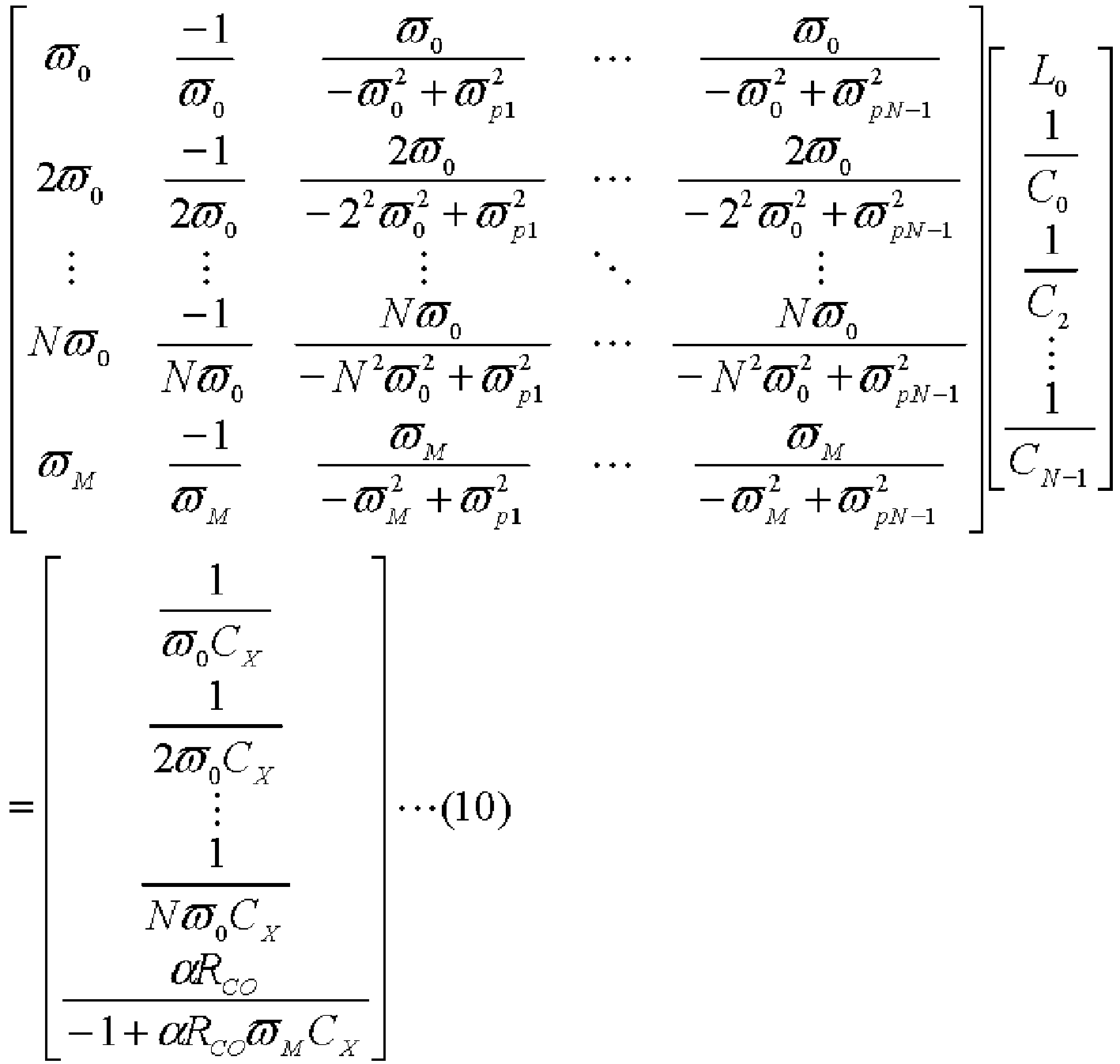
- In the expression (10), ωp1 to ωp(N-1) is given within a range of 0<ωz0<ω0, and tω0<ωpt<ωzt<(t+1)ω0 (t is an integer of 1 to N-1). The respective element values can be thereby obtained from the expression (10).
- In the following, the case of N=3 will be specifically described. In this case, the expressions (9) and (10) correspond to next expressions (11) and (12).
[Expression 11]
[Expression 12]
- Here, when ωM=120π [rad/s] by setting the modulation frequency fM of the PWM signal to 60Hz, ω0=240000π [rad/s], RCO=30 [Ω], α=100, C=1.9 [nF], ωp1=264000 [rad/s], and ωp2=504000 [rad/s], L0, C0, L1, C1, L2, and C2 are as follows.
- L0=136.9 [µH]
- C0=882.3 [nF]
- L1=133.4 [µH]
- C1=10.9 [nF]
- L2=9.4 [µH]
- C2=28.2 [nF]
- By using L0, C0, L1, C1, L2, and C2 obtained by the calculation, β, ωz0, and ωz1 can be also obtained. One example of a method for obtaining β, ωz0, and ωz1 will be described.
- In the case of N=3, the right-hand side of the expression (7) can be transformed as described below.
[Expression 13]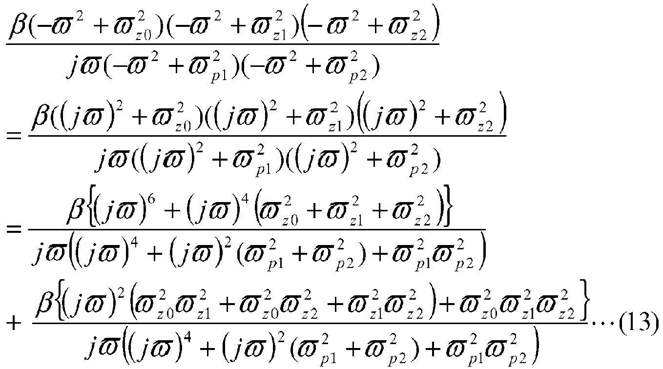
- Moreover, in the case of N=3, a next expression is obtained from the right-hand side of the expression (13).
[Expression 14]
- A relationship described below is obtained by comparing the expressions (13) and (14).
[Expression 15]



- β, ωz0, ωz1, and ωz2 can be obtained based on the expressions (15a) to (15d) and the calculated L0, C0, L1, C1, L2, and C2.
- In the configuration in which the capacitance
suppression element section 50 has the first to N-th circuit sections 531 to 53N as shown inFIG. 4 , the element values of the respective elements of the capacitancesuppression element section 50 can be determined as described above, and β, ωz0, ωz1, ωz2, ..., and ωz(N-1) can be also obtained as described in the case of N=3. - Here, one example of the element configuration of the capacitance
suppression element section 50 has been described by reference toFIG. 4 . However, the configuration of the capacitancesuppression element section 50 is not limited to that inFIG. 4 . For example, in a case of N=2, element configurations shown inFIGS. 5(a) to 5(c) may be employed. In the case of N=3, element configurations shown inFIGS. 6(a) to 6(j) ,FIGS. 7(a) to 7(m) , andFIGS. 8(a) to 8(h) may be further employed.FIGS. 6(a) to 6(J) ,FIGS. 7(a) to 7(m) , andFIGS. 8(a) to 8(h) respectively show examples of the element configuration of the case where N=3 and the number of elements is minimum. In the drawings, C0, C1, C2, L0, L1, and L2 are assigned to capacitance elements and inductance elements in a similar manner to the case inFIG. 4 . Element values of the elements are determined so as to satisfy the expressions (5) and (6). In the case of N=3 inFIG. 4 , and in the case of N=3 as shown in the examples inFIGS. 6(a) to 6(j) ,FIGS. 7(a) to 7(m) , andFIGS. 8(a) to 8(h) , the capacitancesuppression element section 50 includes six reactance elements.FIG. 4 (N=3),FIGS. 6(a) to 6(j) ,FIGS. 7(a) to 7(m) , andFIGS. 8(a) to 8(h) show the examples of the circuit configuration in the case where the capacitancesuppression element section 50 has the minimum number of elements. Thus, in the case of N=3, the capacitancesuppression element section 50 includes at least six reactance elements. - Next, one example of a method for calculating the element values in the case of the circuit configuration shown in
FIG. 6(a) will be described. - The right-hand side of the expression (14) is substituted with s=jω to obtain an expression (16).
[Expression 16]
- Please note that a3, a2, a1, a0, b2, b1, and b0 in the expression (16) are as follows, and are values determined by the values calculated in the case of N=3 in the basic configuration in
FIG. 4 .
[Expression 17]


- The expression (16) corresponds to the expression (7) in the case of N=3, and represents the reactance of the capacitance
suppression element section 50. Thus, the expression (16) may also include the circuit configuration inFIG. 6(a) . Meanwhile, an expression corresponding to the element configuration inFIG. 6(a) is as in an expression (18). As described above, C0, C1, C2, L0, L1, and L2 are assigned to the capacitance elements and the inductance elements inFIG. 6(a) in a similar manner to the case inFIG. 4 . In a following calculation in an expression (18), C0, C1, C2, L0, L1, and L2 are represented as C0a, C1a, C2a, L0a, L1a, and L2a so as to be distinguished from the case inFIG. 4 .
[Expression 18]
- The right-hand side of the expression (16) is transformed into the right-hand side of the expression (18) so as to obtain the respective element values.
[Expression 19]
- By comparing rational function coefficients before and after each transformation of the right-hand side of the expression (16), expressions (20a) to (20f), expressions (21a) to (21g), and expressions (22a) to (22d) can be obtained. From the expressions, the element values of the respective elements in the case of the circuit configuration shown in
FIG. 6(a) , that is, L0a, C0a, L1a, C1a, L2a, and C2a can be obtained.
[Expression 20]

[Expression 21]


[Expression 22]

- In the expressions (20a) to (20f), a3, a2, a1, a0, b2, b1, and bo are obtained by the expressions (17a) to (17g). As described above, the expressions (17a) to (17g) are based on the values calculated in the case of N=3 in the basic configuration in
FIG. 4 . - The element values of the elements of other circuit configurations such as the respective circuit configurations shown in
FIGS. 5(a) to 5(c) may be similarly obtained. That is, the expression (11) is transformed so as to represent the characteristics of the respective circuit configurations. The element values of the respective circuit configurations can be obtained by using a3, a2, a1, a0, b2, and b1, obtained by comparison of rational function coefficients before and after the expression transformation. However, if the element values cannot be determined by the expression transformation or the like described above even when the circuit configuration is determined, the element values may be also determined by using a numerical analytical method. - In the above description, the respective element values of the capacitance
suppression element section 50 are determined by assuming the circuit configuration as shown inFIG. 4 or the like. The circuit configuration of the capacitancesuppression element section 50 may be designed so as to satisfy the expressions (5) and (6). The circuit configuration may be determined by a topology search method, for example. One example of a method for determining the circuit configuration by the topology search method is as follows. - By using any coefficient an to a0 (an, a0≠0), a polynomial expression expressed as an(S2)n+an-1(S2)n-1+...+a0 is defined as Dn. Please note that s=jω.
- Similarly, a polynomial expression expressed as an(p2)n+an-1(p2)n-1+...+a0 is defined as Dn. Please note that p=1/s.
- The circuit structure is obtained by applying following rules.
(Rule 1)
[Expression 23]
(Rule 2)
[Expression 24]
(Rule 3)
[Expression 25]
(Rule 4)
[Expression 26]
(Rule 5)
[Expression 27]
- In the
rules 1 to 4, arrows indicate the direction of expression transformation. Therule 5 indicates that s and 1/p can be mutually converted to each other. - In the expression (7), the circuit structure is obtained by substituting s=jω, and applying the
rules 1 to 5 a plurality of times. - A case in which the above method is applied to the case of N=3 in
FIG. 4 will be described. The expression (7) in the case of N=3 may be expressed as follows.
[Expression 28]
- The right-hand side of the expression (28) can be transformed as follows by applying the
rules 1 to 4 a plurality of times.
[Expression 29]
- In the above transformation, the last expression corresponds to the expression (11). Accordingly, the circuit configuration in the case of N=3 in
FIG. 4 can be obtained. - The number of elements of the capacitance
suppression element section 50 is determined by the order of the harmonic to be suppressed, i.e., the value of N. In the capacitancesuppression element section 50, the number of capacitance elements and the number of inductance elements are equal to each other. When the capacitance elements and the inductance elements are arranged between theopposite terminals suppression element section 50, the capacitance elements and the inductance elements may be arranged according to following rules. - Rule A: Opposite ends of each element are connected to separate relay nodes or terminals.
- Rule B: Three or more elements are not connected in parallel between two nodes.
- Rule C: The same applies to a dual of the rule B.
- Rule D: A closed path in which only two elements are connected in series from one node and return to the same node is not formed.
- Rule E: When a plurality of partial two-terminal circuits are connected in series, the circuits in different order are regarded as the same circuits. Rule F: A circuit in which one element is connected in parallel with remaining elements between the opposite terminals of the capacitance
suppression element section 50 is excluded. - The circuit configuration of the capacitance
suppression element section 50 can be determined more quickly by applying the above rules A to F. - In the switching
circuit 10, the capacitancesuppression element section 50 is connected to thesemiconductor switch element 20. The capacitancesuppression element section 50 is designed so as to satisfy the expressions (5) and (6) as described above. It is thus considered that the parasitic capacitance CX practically does not exist between the terminals of thesemiconductor switch element 20 where the capacitancesuppression element section 50 is connected up to the N-th order harmonic of the clock frequency fCLK of the PWM signal. That is, the parasitic capacitance CX is neutralized by the capacitancesuppression element section 50. A time required to charge and discharge the parasitic capacitance CX can be thereby reduced, so that switching is performed at higher speed in thesemiconductor switch element 20. As a result, the switching speed of the switchingcircuit 10 can be increased, and the power efficiency of the switchingcircuit 10 can be improved. - In the configuration shown in
FIG. 1 , the capacitancesuppression element section 50a is connected between thegate terminal 21 a and thedrain terminal 22a of thesemiconductor switch element 20a. Thus, the parasitic capacitance CGD of thesemiconductor switch element 20a can be cancelled. Similarly, the parasitic capacitance CGD of thesemiconductor switch element 20b can be cancelled by the capacitancesuppression element section 50b. - Overdrive may be performed as a method for increasing the switching speed of the switching
circuit 10 using thesemiconductor switch element 20. However, in this case, the configuration of thedrive circuit 30 may become complicated so as to perform the overdrive as compared to a case in which the overdrive is not performed. Thedrive circuit 30 also needs to have a higher ampacity so as to perform the overdrive. Accordingly, thedrive circuit 30 may be increased in size, or the power efficiency of the switchingcircuit 10 including thedrive circuit 30 may be reduced as compared to the case in which the overdrive is not performed. In this case, even when the high-speed switching is achieved by the overdrive, an improvement in the power efficiency by the high-speed switching itself may not be obtained. - Meanwhile, in the switching
circuit 10, the capacitancesuppression element section 50 neutralizes the parasitic capacitance CX itself to achieve the high-speed switching. Accordingly, the switching speed of the switchingcircuit 10 can be increased and the power efficiency can be improved as described above without performing the overdrive. - Although it is described that the capacitance
suppression element section 50 can achieve the state in which the parasitic capacitance CX practically does not exist in the present embodiment, the capacitancesuppression element section 50 only needs to reduce the influence of the parasitic capacitance CX when the capacitancesuppression element section 50 is connected. For example, the circuit configuration of the capacitancesuppression element section 50 and the element values of the elements of the capacitancesuppression element section 50 may be set to values with which an equivalent capacitance of the terminal value where the capacitancesuppression element section 50 is connected becomes 1/10 or less of the original parasitic capacitance CX by connecting the capacitancesuppression element section 50. The element values of the elements of the capacitancesuppression element section 50 may be also set to values with which the equivalent capacitance becomes half or less of the original parasitic capacitance CX. - It is described that the switching
circuit 10 includes the inductance element LL as the inductive load as one example in the present embodiment. When including such inductive load, the switchingcircuit 10 can be used for an inverter or the like. For example, by connecting a motor as the load instead of the inductance element LL, the switchingcircuit 10 can be used for driving the motor. - Next, the change in the characteristics of the switching
circuit 10 by the capacitancesuppression element section 50 will be more specifically described by reference to simulation results. Simulations were performed by using NGSPICE. -
FIG. 9 is a diagram illustrating a model of a semiconductor switch element for simulations. A MOS field-effect transistor was assumed to be used as thesemiconductor switch element 20. It was assumed that parasitic resistances RG and RI existed in addition to the parasitic capacitances CGS, CDS, and CGD in thesemiconductor switch element 20. - Device parameters of the
semiconductor switch element 20 were set as follows.
Threshold voltage VT=2 V
Transfer conductance parameter K=420 mS/V
Channel length modulation coefficient λ=0 mV-1
Parasitic capacitance CGS between the gate and the source=700 pF
Parasitic capacitance CDS between the drain and the source=77 pF
Parasitic capacitance CGD between the gate and the drain=63 pF
Parasitic resistance RG=1 mΩ
Parasitic resistance RI=1 mΩ -
FIG. 10 is a circuit diagram for simulations corresponding to the switchingcircuit 10 shown inFIG. 1 . In the following, elements corresponding to those inFIG. 1 are assigned the same reference numerals for the convenience of description. - In
FIG. 10 , the firstdrive circuit section 31 and the seconddrive circuit section 32 of thedrive circuit 30 shown inFIG. 1 are shown assignal sources semiconductor switch elements semiconductor switch elements FIG. 9 . - Element values or the like in a simulation circuit model shown in
FIG. 10 were set as follows.
Clock frequency fCLK of the PWM signal supplied from thesignal sources
Modulation frequency fM of the PWM signal supplied from thesignal sources
Resistance value of the resistance RCO (Output impedance RCO of thesignal sources gate terminals
Positive voltage VDD supplied to thedrain terminal 22a = 400 V
Negative voltage VSS supplied to the source terminal 23b = -400 V
Voltage supplied to thesignal sources source terminals third power sources
Element value (inductance) of the inductance element LL: 2.5 mH
Element value (resistance value) of the resistance RL: 10 Ω - The basic configuration shown in
FIG. 4 was employed for the capacitancesuppression element sections suppression element sections - The element values in the case of N=1, that is, when the parasitic capacitance CX is suppressed with respect to the clock frequency fCLK are as shown in Table 1.
[Table 1] L0 [µH] 22842.8 C0 [nF] 886.7 - The element values in the case of N=3, that is, when the parasitic capacitance CX is suppressed with respect to up to a third-order harmonic of the clock frequency fCLK are as shown in Table 2.
[Table 2] L0 [µH] 4138.4 C0 [nF] 885.1 L1 [µH] 4031.5 C1 [nF] 0.1 L2 [µH] 426.7 C2 [nF] 0.9 - The element values in the case of N=5, that is, when the parasitic capacitance CX is suppressed with respect to up to a fifth-order harmonic of the clock frequency fCLK are as shown in Table 3.
[Table 3] L0 [µH] 1367.4 C0 [nF] 884.7 L1 [µH] 3576.9 C1 [nF] 0.4 L2 [µH] 521.8 C2 [nF] 0.8 L3 [µH] 136.4 C3 [nF] 1.3 L4 [µH] 36.5 C4 [nF] 2.9 -
Next simulations simulations - In the
simulation 1, power efficiency was calculated in simulations 1a and 1b based on conditions described below. - The power efficiency was calculated by (output voltage Vout×output current Iout)/(supply voltage VDD×supply current IEE)×100(%). Here, the output current Iout is a current flowing through the inductance LL. The supply current IEE is a current flowing into the
drain terminal 22a. - The simulation was performed with CGS=700 pF, CGD=0, and CDS=77 pF. The power efficiency in this case was 96%.
- The simulation was performed with CGS=700 pF, CGD=63 pF, and CDS=77 pF. The power efficiency in this case was 89%.
- By comparing the result of the simulation 1a and the result of the simulation 1b, it has been found that the power efficiency can be improved by reducing the parasitic capacitance of the semiconductor switch element 20 (the parasitic capacitance CGD in the simulation 1a as one example).
- In the
simulation 2, simulations 2a to 2c were performed such that the parasitic capacitance CGD was suppressed by use of the capacitancesuppression element section 50 by setting the values of the parasitic capacitances CGD, CGS, and CDS of thesemiconductor switch element 20 to the values indicated as the device parameters above. A simulation 2d was also performed for comparison as a case in which the capacitancesuppression element section 50 was not connected. - The simulation was performed by employing the configuration in the case of N=1 as the configuration of the capacitance
suppression element section 50, and power efficiency and time ratio were calculated. Total harmonic distortion (THD) was also calculated so as to examine the influence of the capacitance suppression element section on the THD. - The simulation was performed by employing the configuration in the case of N=3 as the configuration of the capacitance
suppression element section 50, and power efficiency and time ratio were calculated. THD was also calculated in the present simulation in a similar manner to the simulation 2a. - The simulation was performed by employing the configuration in the case of N=5 as the configuration of the capacitance
suppression element section 50, and power efficiency and time ratio were calculated. THD was also calculated in the present simulation in a similar manner to the simulation 2a. - The simulation was performed for the case in which the capacitance
suppression element section 50 was not connected, and power efficiency and time ratio were calculated. -
FIG. 11 is a diagram showing the calculation results of the power efficiency and the time ratio in the simulations 2a to 2d. A horizontal axis represents the performed simulations. A vertical axis represents the power efficiency (%) and the time ratio (%). - From
FIG. 11 , it can be understood that the power efficiency and the time ratio are both improved in the simulations 2a, 2b, and 2c using the capacitancesuppression element section 50 as compared to the result of the simulation 2d in which the parasitic capacitance CGD is not cancelled by the capacitancesuppression element section 50. -
FIG. 12 is a diagram showing the calculation results of the THD in the simulations 2a, 2b, and 2c. A horizontal axis represents the performed simulations. A vertical axis represents the total harmonic distortion: THD (%). As shown inFIG. 12 , it can be understood that as the order of the harmonic of the clock frequency fCLK increases, the THD decreases when the capacitancesuppression element section 50 is provided. Accordingly, it is understood that an increase in the THD can be reduced in the switchingcircuit 10 including the capacitancesuppression element section 50. -
FIG. 13 is a circuit diagram illustrating the schematic configuration of a switching circuit according to a second embodiment of the present invention. A switchingcircuit 70 is a differential switching circuit. - The switching
circuit 70 includes foursemiconductor switch elements semiconductor switch elements 20a to 20d are the same semiconductor switch element as that of the first embodiment. In the following description, thesemiconductor switch elements 20a to 20d may be sometimes referred to assemiconductor switch element 20 in a similar manner to the case of the first embodiment. The switchingcircuit 70 may includedrive circuits gate terminals semiconductor switch elements drive circuits semiconductor switch elements FIG. 11 , only onedrive circuit 30 may be employed as in the case of the first embodiment. Thedrive circuit 30a and thedrive circuit 30b correspond to the firstdrive circuit section 31 and the seconddrive circuit section 32. - The configuration of the switching
circuit 70 will be described. A drain terminal (an output terminal) 22a of the semiconductor switch element (a first semiconductor switch element) 20a and a drain terminal (an output terminal) 22c of the semiconductor switch element (a third semiconductor switch element) 20c are connected to each other. A source terminal (a common terminal) 23b of the semiconductor switch element (a second semiconductor switch element) 20b and a source terminal (a common terminal) 23d of the semiconductor switch element (a fourth semiconductor switch element) 20d are connected to each other. Afirst power source 40 and asecond power source 41 are respectively connected to a connection point between thedrain terminal 22a and thedrain terminal 22c, and a connection point between thesource terminal 23b and thesource terminal 23d. Thefirst power source 40 supplies a positive voltage VDD to thedrain terminals second power source 41 supplies a negative voltage VSS to thesource terminals - The
semiconductor switch elements semiconductor switch elements semiconductor switch element 20c and adrain terminal 22d of thesemiconductor switch element 20d are connected to each other. A connection point between asource terminal 23a and adrain terminal 22b, and a connection point between thesource terminal 23c and thedrain terminal 22d are connected via aload 80. Theload 80 may be an inductive load such as an inductance element in a similar manner to the first embodiment, or may be a resistive load. For example, when a motor is connected as theload 80, the motor may be driven. - The
drive circuits gate terminals semiconductor switch elements drive circuits gate terminals semiconductor switch elements gate terminals 21 a to 21d have the same clock frequency fCLK. Resistances RCO between the respectivesemiconductor switch elements 20a to 20d and thecorresponding drive circuits 30a to 30d represent output impedances of thedrive circuits 30a to 30d respectively connected to thegate terminals 21 a to 21 d of thesemiconductor switch elements 20a to 20d.Third power sources 42a to 42d are respectively connected between thesource terminals 23a to 23d of thesemiconductor switch elements 20a to 20d and thedrive circuits 30a to 30d. Positive poles of thethird power sources 42a to 42d are connected to thecorresponding source terminals 23a to 23d. Negative poles of thethird power sources 42a to 42d are connected to thecorresponding drive circuits 30a to 30d. Accordingly, predetermined negative voltages based on thesource terminals 23a to 23d are supplied to thedrive circuits 30a to 30d in a similar manner to the first embodiment. The magnitude of the predetermined negative voltage may be equal to that of the negative voltage supplied from thethird power source - In the above configuration, while the
drive circuits semiconductor switch elements drive circuits semiconductor switch elements semiconductor switch elements semiconductor switch elements FIG. 13 . Meanwhile, when thesemiconductor switch elements semiconductor switch elements FIG. 13 . Accordingly, the direction of a current flowing through theload 80 can be switched according to the PWM signals. - To improve the power efficiency in accordance with the switching, capacitance
suppression element sections semiconductor switch elements semiconductor switch elements suppression element sections FIG. 13 shows a configuration in which the capacitancesuppression element sections gate terminals drain terminals semiconductor switch elements suppression element sections suppression element sections suppression element section 50 in a similar manner to the case of the first embodiment. - In the switching
circuit 70,capacitance elements drain terminal 22b of thesemiconductor switch element 20b and thegate terminal 21d of thesemiconductor switch element 20d, and between thegate terminal 21b of thesemiconductor switch element 20b and thedrain terminal 22d of thesemiconductor switch element 20d. A capacitance C90 of the capacitance element (a first capacitance element) 90 is substantially equal to the parasitic capacitance CGD between thegate terminal 21d and thedrain terminal 22d of thesemiconductor switch element 20d at an N-th order harmonic of the PWM signal. Similarly, a capacitance C91 of the capacitance element (a second capacitance element) 91 is substantially equal to the parasitic capacitance CGD between thegate terminal 21b and thedrain terminal 22b of thesemiconductor switch element 20b. - By connecting the
capacitance elements semiconductor switch elements FIG. 14 . -
FIG. 14 is a diagram for explaining the principle that the parasitic capacitance of the semiconductor switch element can be suppressed by connecting the capacitance element.FIG. 14 is a model diagram for calculating a capacitance component anticipated from thegate terminal 21d in thesemiconductor switch element 20d having a differential circuit. - In a circuit model shown in
FIG. 14 , acapacitance element 102 is connected between afirst terminal 100 and asecond terminal 101, and acapacitance element 104 having the same capacitance as that of thecapacitance element 102 is connected between thefirst terminal 100 and athird terminal 103. Thecapacitance element 102 represents the parasitic capacitance CGD, and thecapacitance element 104 corresponds to thecapacitance element 90. Asignal source 105 is connected to thefirst terminal 100, andvoltage sources second terminal 101 and thethird terminal 103. - In the model shown in
FIG. 14 , thefirst terminal 100 corresponds to thegate terminal 21d of thesemiconductor switch element 20d. Thesignal source 105 supplies a gate voltage VX to thefirst terminal 100 so as to represent the input of the PWM signal into thegate terminal 21d. Thesecond terminal 101 corresponds to thedrain terminal 22d of thesemiconductor switch element 20d. Thevoltage source 106 supplies a voltage VD to thesecond terminal 101 so as to represent the voltage of thedrain terminal 22d. Thethird terminal 103 corresponds to thedrain terminal 22b of thesemiconductor switch element 20b. It is assumed that a drain potential of thedrain terminal 22b of thesemiconductor switch element 20b is opposite to a drain potential of thedrain terminal 22d of thesemiconductor switch element 20d. Thus, a drain voltage (-VD) is supplied to the third terminal 103 from thevoltage source 107. - An amount of charge flowing into the
first terminal 100 as thegate terminal 21d from thesecond terminal 101 and thethird terminal 103 is CGD(VD-VX)+CGD(-VD-VX)=-2CGDVX. Thus, the parasitic capacitance CGD between the gate and the drain equivalently does not exist, and it appears that a capacitance having the value of 2CGD exists between thegate terminal 21d and the ground (that is, the source terminal). - As described above, when the
capacitance element 90 is provided as shown inFIG. 13 , the parasitic capacitance CGD between the gate and the drain equivalently does not exist at the N-th order harmonic (a so-called fundamental wave in a case of N=1) of the PWM signal. Thus, the influence of the parasitic capacitance CGD of thesemiconductor switch element 20d can be neutralized or cancelled. Although thesemiconductor switch element 20d has been mainly described here, the same applies to thesemiconductor switch element 20b. That is, when thecapacitance element 91 is provided as shown inFIG. 13 , the influence of the parasitic capacitance CGD of thesemiconductor switch element 20b can be neutralized or cancelled at the N-th order harmonic of the PWM signal. The parasitic capacitance CGD between the gate and the drain affects the switching speed the most in thesemiconductor switch elements 20a to 20d. Thus, when the influence of the parasitic capacitance CGD between the gate and the drain is reduced in thesemiconductor switch elements semiconductor switch elements - Although it is described that the
capacitance elements capacitance elements capacitance elements capacitance elements capacitance elements - In the switching
circuit 70, the capacitancesuppression element sections semiconductor switch elements capacitance elements semiconductor switch elements semiconductor switch elements 20a to 20d can be increased, and the power efficiency can be improved in a similar manner to the case of the first embodiment. Since the influence of the parasitic capacitance CGD is reduced by using the capacitancesuppression element sections capacitance elements capacitance elements semiconductor switch elements circuit 70 can be more easily designed. Accordingly, the configuration of the switchingcircuit 70 is more effectively employed when there is a difference in device parameters of thesemiconductor switch elements 20a to 20d. - The point that the power efficiency can be improved in the switching
circuit 70 will be described by reference to simulation results. -
FIG. 15 is a model for simulations corresponding to the switchingcircuit 70 shown inFIG. 13 . In the following, elements corresponding to those inFIG. 13 are assigned the same reference numerals for the convenience of description. In a circuit model shown inFIG. 15 , theload 80 is represented by a series circuit of an inductance element LL1, a resistance RL, and an inductance element LL2. In simulations, a voltage to the ground of the connection point between the source terminal 23a of thesemiconductor switch element 20a and thedrain terminal 22b of thesemiconductor switch element 20b was set as an output voltage Vout. In the simulation circuit model, thesemiconductor switch elements 20a to 20d had the configuration shown inFIG. 9 in a similar manner to the first embodiment. The device parameters of thesemiconductor switch elements 20a to 20d were the same as the device parameters described in the first embodiment. Thecapacitance elements - Element values or the like in the simulation circuit model shown in
FIG. 15 were set as follows. - Clock frequency fCLK of the PWM signal supplied from the
drive circuits 30a to 30d = 120 kHz - Modulation frequency fM of the PWM signal supplied from the
drive circuits 30a to 30d = 60 kHz - Resistance value of the resistance RCO: 30 Ω
- Positive voltage VDD supplied to the
drain terminals - Negative voltage VSS supplied to the
source terminals - Voltage supplied to the
drive circuits 30a to 30d based on thesource terminals 23a to 23d from thethird power sources 42a to 42d: -13 V - Element value (inductance) of the inductance elements LL1 and LL2:2.5×1/2 mH
- Element value (resistance value) of the resistance RL: 10 Ω
- Following
simulations - The simulation was performed by assuming a case in which none of the
capacitance elements suppression element sections semiconductor switch elements 20a to 20d were set to the values indicated as the device parameters. - The simulation was performed by assuming a case in which the parasitic capacitance CGD between the gate and the drain of each of the
semiconductor switch elements 20 was cancelled by thecapacitance elements suppression element sections semiconductor switch elements 20a to 20d was set to 0 as an ideal state. - The simulation was performed by assuming that the parasitic capacitances CGD of the
semiconductor switch elements 20a to 20d were neutralized by the capacitancesuppression element sections 50 without providing thecapacitance elements - The simulation was performed on the same conditions as the
simulation 3 except that thecapacitance elements -
FIGS. 16 to 19 are diagrams respectively showing the results of thesimulations 3 to 6.FIGS. 16 to 19 show changes in voltages VGS1a and VGS2a between the gate and the source of thesemiconductor switch element 20 and the output voltage Vout with respect to time. A horizontal axis represents the time [µs], and a vertical axis represents the voltages VGS [V] between the gate and the source and the output voltage Vout [V].FIGS. 16 to 19 show VGSa as VGS in thesemiconductor switch element 20a at an upper left position inFIG. 15 , VGSb as VGS in thesemiconductor switch element 20b at a lower left position inFIG. 15 , and the output voltage Vout as the voltage to the ground of the connection point between thesemiconductor switch element 20a and thesemiconductor switch element 20b. - By comparing
FIGS. 16 ,17 , and18 , it can be understood that there is a more rapid voltage change, particularly, a more rapid change in the output voltage Vout than that in the case shown inFIG. 16 by providing the capacitancesuppression element sections semiconductor switch elements FIG. 18 approaches to an ideal state shown inFIG. 17 . - Also, by comparing
FIGS. 17 ,18 , and19 , it can be understood that there is a still more rapid voltage change, particularly, a still more rapid change in the output voltage Vout than that in the case shown inFIG. 18 by providing the capacitancesuppression element sections 50 and also connecting the capacitance elements, so that the results shown inFIG. 19 approaches to an ideal state shown inFIG. 17 . - Although the example in which the
capacitance elements semiconductor switch elements semiconductor switch elements capacitance elements gate terminals capacitance elements semiconductor switch elements capacitance elements - Although various embodiments of the present invention have been described above, the present invention is not limited to the various embodiments described above, and various modifications may be made without departing from the scope of the present invention. For example, the semiconductor switch element of the switching circuit is not limited to the MOS field-effect transistor described above. For example, the semiconductor switch element may be an insulated gate bipolar transistor, a junction field-effect transistor, or a junction bipolar transistor. Alternatively, the semiconductor switch element may be a thyristor. When the semiconductor switch element is the insulated gate bipolar transistor or the junction bipolar transistor, the semiconductor switch element has a gate terminal as the input terminal, a collector terminal as the output terminal, and an emitter terminal as the common terminal. When the semiconductor switch element is the junction field-effect transistor, the semiconductor switch element has a gate terminal as the input terminal, a drain terminal as the output terminal, and a source terminal as the common terminal in a similar manner to the case of the MOS field-effect transistor. When the semiconductor switch element is the thyristor, the semiconductor switch element has a gate terminal as the input terminal, an anode terminal as the output terminal, and a cathode terminal as the common terminal.
- Although it is described that the plurality of semiconductor switch elements of the switching circuit have the same configuration, the plurality of semiconductor switch elements may have different configurations. The capacitance suppression element sections respectively connected to the plurality of semiconductor switch elements may also have different configurations. The number of semiconductor switch elements of the switching circuit is also not limited to 2 or 4 described above. The switching circuit only needs to have at least one semiconductor switch element.
- Although the pulse-like signal supplied to the semiconductor switch element is the PWM signal in the various embodiments described above, any pulse-like signal may be employed as long as the ON/OFF switching of the semiconductor switch element can be controlled.
- 10... switching circuit; 20... semiconductor switch element; 20a... semiconductor switch element(first semiconductor switch element) ; 20b...semiconductor switch element(second semiconductor switch element); 20c... semiconductor switch element(third semiconductor switch element); 20d... semiconductor switch element(fourth semiconductor switch element); 21, 21a, 21b, 21c, 21 d... gate terminal(input terminal); 22, 22a, 22b, 22c, 22d... drain terminal(output terminal); 23, 23a, 23b, 23c, 23d...source terminal(common terminal); 30, 30a, 30b, 30c, 30d...drive circuit; 50, 50a, 50b, 50c...capacitance suppression element section; 531...first circuit section; 53i...i-th circuit section (i is an integer of 2 to N); 70... switching circuit; 90, 91... capacitance element(first and second capacitance elements)
- Further embodiments of the invention are defined in the following list of embodiments which combine with or supplement the aforegoing description:
- [Embodiment 1] A switching circuit comprising at least one semiconductor switch element having an input terminal, an output terminal, and a common terminal, a pulse-like signal being applied between the input terminal and the common terminal to switch a current between the output terminal and the common terminal,
further comprising a capacitance suppression element section connected at least one of between the input terminal and the output terminal, between the input terminal and the common terminal, and between the output terminal and the common terminal,
wherein the capacitance suppression element section reduces a parasitic capacitance between the terminals of the semiconductor switch element, where the capacitance suppression element section is connected, to less than that obtained when the capacitance suppression element section is not connected, at a frequency N times (N is an integer of 1 or more) as high as a clock frequency of the pulse-like signal. - [Embodiment 2] A switching circuit comprising four semiconductor switch elements each having an input terminal, an output terminal, and a common terminal, an output terminal of a first semiconductor switch element out of the four semiconductor switch elements and an output terminal of a third semiconductor switch element out of the four semiconductor switch elements being connected to each other, a common terminal of a second semiconductor switch element out of the four semiconductor switch elements and a common terminal of a fourth semiconductor switch element out of the four semiconductor switch elements being connected to each other, a common terminal of the first semiconductor switch element and an output terminal of the second semiconductor switch element being connected to each other, a common terminal of the third semiconductor switch element and an output terminal of the fourth semiconductor switch element being connected to each other, and a pulse-like signal being applied to each input terminal of the first to fourth semiconductor switch elements such that the second and third semiconductor switch elements are in an OFF state when the first and fourth semiconductor switch elements are in an ON state and the second and third semiconductor switch elements are in an ON state when the first and fourth semiconductor switch elements are in an OFF state,
further comprising a capacitance suppression element section connected at least one of between the input terminal and the output terminal, between the input terminal and the common terminal, and between the output terminal and the common terminal of at least one of the four semiconductor switch elements,
wherein the capacitance suppression element section reduces a parasitic capacitance between the terminals of the semiconductor switch element, where the capacitance suppression element section is connected, to less than that obtained when the capacitance suppression element section is not connected, at a frequency N times (N is an integer of 1 or more) as high as a clock frequency of the pulse-like signal. - [Embodiment 3] The switching circuit according to
embodiment 2, further comprising
a first capacitance element connected between the output terminal of the second semiconductor switch element and the input terminal of the fourth semiconductor switch element, and
a second capacitance element connected between the input terminal of the second semiconductor switch element and the output terminal of the fourth semiconductor switch element,
wherein the first capacitance element has a capacitance to reduce a parasitic capacitance between the input terminal and the output terminal of the fourth semiconductor switch element to less than that obtained when the first capacitance element is not connected at a frequency N times (N is an integer of 1 or more) as high as the clock frequency of the pulse-like signal supplied to the fourth semiconductor switch element, and
the second capacitance element has a capacitance to reduce a parasitic capacitance between the input terminal and the output terminal of the second semiconductor switch element to less than that obtained when the second capacitance element is not connected at a frequency N times (N is an integer of 1 or more) as high as the clock frequency of the pulse-like signal supplied to the second semiconductor switch element. - [Embodiment 4] The switching circuit according to any one of
embodiments 1 to 3,
wherein the pulse-like signal is a PWM signal, and
the capacitance suppression element section is configured to satisfy expressions (1) and (2) when a reactance of the capacitance suppression element section is a function X(ω) of an angular frequency:
[Expression 1]
[Expression 2]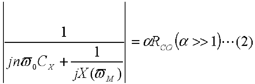
(in the expressions (1) and (2), j represents an imaginary unit, ω0 represents a product of a clock frequency of the PWM signal and 2π, ωM represents a product of a modulation frequency of the PWM signal and 2π, CX represents a parasitic capacitance between the terminals of the semiconductor switch element as the parasitic capacitance between the terminals of the semiconductor switch element where the capacitance suppression element section is connected, RCO represents an output impedance of a drive circuit that is connected to the input terminal of the semiconductor switch element where the capacitance suppression element section is connected and supplies the PWM signal). - [Embodiment 5] The switching circuit according to embodiment 4,
wherein the function X(ω) is expressed by an expression (3):
[Expression 3]
(in the expression (3), when t is an integer of 1 to N-1, ωz0 is a value that satisfies 0<ωz0<ω0, ωzt and ωpt are values that satisfy tω0<ωpt<ωzt<(t+1)ω0, and β is any value). - [Embodiment 6] The switching circuit according to
embodiment 5,
wherein the capacitance suppression element section is connected between the input terminal and the output terminal of the semiconductor switch element. - [Embodiment 7] The switching circuit according to any one of
embodiments 1 to 6,
wherein N is 2 or more,
the capacitance suppression element section has first to N-th circuit sections connected in series,
the first circuit section is composed of an inductance element and a capacitance element connected in series, and
an i-th circuit section (i is an integer of 2 to N) out of the second to N-th circuit sections is composed of an inductance element and a capacitance element connected in parallel. - [Embodiment8] The switching circuit according to
embodiment 7,
wherein when element values of the inductance element and the capacitance element of the first circuit section are respectively L0 and C0, and element values of the inductance element and the capacitance element of the i-th circuit section are respectively Li-1 and Ci-1,
the element values of the inductance element and the capacitance element of the first circuit section and an element value of a capacitance element of each of the second to N-th circuit sections satisfy an expression (4), and
Li-1 is 1/(Ci-1(ωp(i-1))2):
[Expression 4]
Claims (2)
- A switching circuit comprising first to fourth semiconductor switch elements each having an input terminal, an output terminal, and a common terminal, an output terminal of the first semiconductor switch element and an output terminal of the third semiconductor switch element being connected to each other, a common terminal of the second semiconductor switch element and a common terminal of the fourth semiconductor switch element being connected to each other, a common terminal of the first semiconductor switch element and an output terminal of the second semiconductor switch element being connected to each other, a common terminal of the third semiconductor switch element and an output terminal of the fourth semiconductor switch element being connected to each other, and a pulse-like signal being applied to each input terminal of the first to fourth semiconductor switch elements such that the second and third semiconductor switch elements are in an OFF state when the first and fourth semiconductor switch elements are in an ON state and the second and third semiconductor switch elements are in an ON state when the first and fourth semiconductor switch elements are in an OFF state,
further comprising a first capacitance element connected between the output terminal of the second semiconductor switch element and the input terminal of the fourth semiconductor switch element, and
a second capacitance element connected between the input terminal of the second semiconductor switch element and the output terminal of the fourth semiconductor switch element,
wherein the first capacitance element has a capacitance to reduce a parasitic capacitance between the input terminal and the output terminal of the fourth semiconductor switch element to less than that obtained when the first capacitance element is not connected at a frequency N times (N is an integer of 1 or more) as high as a clock frequency of the pulse-like signal supplied to the fourth semiconductor switch element, and
the second capacitance element has a capacitance to reduce a parasitic capacitance between the input terminal and the output terminal of the second semiconductor switch element to less than that obtained when the second capacitance element is not connected at a frequency N times (N is an integer of 1 or more) as high as a clock frequency of the pulse-like signal supplied to the second semiconductor switch element. - The switching circuit according to claim 1,
wherein the capacitance of the first capacitance element is substantially equal to the parasitic capacitance between the input terminal and the output terminal of the fourth semiconductor switch element, and
the capacitance of the second capacitance element is substantially equal to the parasitic capacitance between the input terminal and the output terminal of the second semiconductor switch element.
Applications Claiming Priority (2)
| Application Number | Priority Date | Filing Date | Title |
|---|---|---|---|
| JP2011126337A JP5580782B2 (en) | 2011-06-06 | 2011-06-06 | Switching circuit |
| EP12796228.0A EP2720373A4 (en) | 2011-06-06 | 2012-04-02 | SWITCHING CIRCUIT |
Related Parent Applications (1)
| Application Number | Title | Priority Date | Filing Date |
|---|---|---|---|
| EP12796228.0A Division EP2720373A4 (en) | 2011-06-06 | 2012-04-02 | SWITCHING CIRCUIT |
Publications (2)
| Publication Number | Publication Date |
|---|---|
| EP2928078A1 true EP2928078A1 (en) | 2015-10-07 |
| EP2928078B1 EP2928078B1 (en) | 2017-03-22 |
Family
ID=47261203
Family Applications (2)
| Application Number | Title | Priority Date | Filing Date |
|---|---|---|---|
| EP12796228.0A Withdrawn EP2720373A4 (en) | 2011-06-06 | 2012-04-02 | SWITCHING CIRCUIT |
| EP15166026.3A Not-in-force EP2928078B1 (en) | 2011-06-06 | 2012-04-02 | Switching circuit |
Family Applications Before (1)
| Application Number | Title | Priority Date | Filing Date |
|---|---|---|---|
| EP12796228.0A Withdrawn EP2720373A4 (en) | 2011-06-06 | 2012-04-02 | SWITCHING CIRCUIT |
Country Status (6)
| Country | Link |
|---|---|
| US (1) | US8760223B2 (en) |
| EP (2) | EP2720373A4 (en) |
| JP (1) | JP5580782B2 (en) |
| CN (1) | CN103548265B (en) |
| TW (1) | TWI540832B (en) |
| WO (1) | WO2012169271A1 (en) |
Families Citing this family (11)
| Publication number | Priority date | Publication date | Assignee | Title |
|---|---|---|---|---|
| JP5759286B2 (en) * | 2011-06-27 | 2015-08-05 | 住友電気工業株式会社 | Switching circuit |
| US20150072615A1 (en) * | 2013-09-06 | 2015-03-12 | Qualcomm Incorporated | Systems and methods for reducing transmission interference with a parasitic loop |
| US9515645B2 (en) * | 2014-06-03 | 2016-12-06 | Infineon Technologies Ag | System and method for a radio frequency switch |
| ES2794615T3 (en) * | 2015-06-30 | 2020-11-18 | Fronius Int Gmbh | Circuit arrangement for controlling a transistor |
| US9667191B2 (en) * | 2015-07-14 | 2017-05-30 | Texas Instruments Incorporated | Ultrasound lens cleaner driver with frequency selectable oscillator |
| US9876518B2 (en) * | 2015-09-22 | 2018-01-23 | The Regents Of The University Of California | Capacitive passive mixer baseband receiver with broadband harmonic rejection |
| FR3043863B1 (en) * | 2015-11-16 | 2017-12-22 | Valeo Japan Co Ltd | METHOD AND SYSTEM FOR DISSIPATING A DETERMINED ENERGY QUANTITY STORED IN A CAPACITY AND COMPUTER PROGRAM PRODUCT STORING AN EXECUTABLE CODE FOR IMPLEMENTING SAID METHOD |
| CN107968584B (en) * | 2016-10-19 | 2020-01-10 | 徐夫子 | Resonance damper |
| JP6653285B2 (en) * | 2017-03-21 | 2020-02-26 | 矢崎総業株式会社 | Switching control device |
| JP7444251B2 (en) * | 2020-05-29 | 2024-03-06 | 日本電信電話株式会社 | amplifier circuit |
| WO2021240784A1 (en) * | 2020-05-29 | 2021-12-02 | 日本電信電話株式会社 | Amplification circuit |
Citations (3)
| Publication number | Priority date | Publication date | Assignee | Title |
|---|---|---|---|---|
| JPH0747993Y2 (en) | 1990-02-15 | 1995-11-01 | 三洋電機株式会社 | Switching control power supply circuit |
| US6377095B1 (en) * | 2000-10-10 | 2002-04-23 | National Semiconductor Corporation | Digital-edge-rate control LVDS driver |
| US20060044066A1 (en) * | 2004-09-01 | 2006-03-02 | Leonard Forbes | CMOS amplifiers with frequency compensating capacitors |
Family Cites Families (16)
| Publication number | Priority date | Publication date | Assignee | Title |
|---|---|---|---|---|
| US4533836A (en) * | 1983-01-12 | 1985-08-06 | Pacific Electro Dynamics, Inc. | Multiple voltage switching power supply having output voltage limiting |
| US4811192A (en) * | 1986-10-15 | 1989-03-07 | Fanuc Ltd. | Inverter apparatus |
| JPH0747993A (en) | 1993-08-03 | 1995-02-21 | Mitsubishi Heavy Ind Ltd | Magnetic tape for guiding underwater inspection robots |
| JPH098501A (en) * | 1995-06-15 | 1997-01-10 | Hitachi Ltd | High frequency switch |
| DE19823917A1 (en) * | 1997-06-03 | 1998-12-10 | Fuji Electric Co Ltd | Converter for producing multiphase AC current |
| JP3310203B2 (en) * | 1997-07-25 | 2002-08-05 | 株式会社東芝 | High frequency switch device |
| JP2002171139A (en) * | 2000-12-01 | 2002-06-14 | Matsushita Electric Ind Co Ltd | High frequency amplifier |
| JP3892865B2 (en) * | 2003-09-19 | 2007-03-14 | 株式会社東芝 | Semiconductor device, communication device, and inspection method of semiconductor device |
| JP2005176331A (en) * | 2003-11-21 | 2005-06-30 | Matsushita Electric Ind Co Ltd | Amplifier and transmitter and communication device using the same |
| US7199652B2 (en) * | 2003-11-21 | 2007-04-03 | Matsushita Electric Industrial Co., Ltd. | Amplifier; and transmitter and communication device incorporating the same |
| US7633357B2 (en) * | 2004-03-24 | 2009-12-15 | Mitsubishi Electric Corporation | SPST switch, SPDT switch and MPMT switch |
| CN101310438A (en) * | 2005-08-04 | 2008-11-19 | 加利福尼亚大学董事会 | Resonant common-source/common-emitter structure for high-gain amplification |
| JP2007336048A (en) * | 2006-06-13 | 2007-12-27 | Nec Electronics Corp | High frequency power amplifier |
| JP5141117B2 (en) * | 2006-07-24 | 2013-02-13 | セイコーエプソン株式会社 | Liquid ejecting apparatus and printing apparatus |
| TWI350053B (en) * | 2008-01-25 | 2011-10-01 | Univ Nat Taiwan | Single-pole single-throw switch circuit device |
| JP2010028522A (en) * | 2008-07-22 | 2010-02-04 | Seiko Epson Corp | Semiconductor device |
-
2011
- 2011-06-06 JP JP2011126337A patent/JP5580782B2/en not_active Expired - Fee Related
-
2012
- 2012-04-02 EP EP12796228.0A patent/EP2720373A4/en not_active Withdrawn
- 2012-04-02 WO PCT/JP2012/058991 patent/WO2012169271A1/en not_active Ceased
- 2012-04-02 EP EP15166026.3A patent/EP2928078B1/en not_active Not-in-force
- 2012-04-02 CN CN201280024710.7A patent/CN103548265B/en not_active Expired - Fee Related
- 2012-05-10 TW TW101116712A patent/TWI540832B/en not_active IP Right Cessation
- 2012-06-06 US US13/490,101 patent/US8760223B2/en not_active Expired - Fee Related
Patent Citations (3)
| Publication number | Priority date | Publication date | Assignee | Title |
|---|---|---|---|---|
| JPH0747993Y2 (en) | 1990-02-15 | 1995-11-01 | 三洋電機株式会社 | Switching control power supply circuit |
| US6377095B1 (en) * | 2000-10-10 | 2002-04-23 | National Semiconductor Corporation | Digital-edge-rate control LVDS driver |
| US20060044066A1 (en) * | 2004-09-01 | 2006-03-02 | Leonard Forbes | CMOS amplifiers with frequency compensating capacitors |
Non-Patent Citations (1)
| Title |
|---|
| GALAL S ET AL: "10-Gb/s limiting amplifier and laser/modulator driver in 0.18-/spl mu/m CMOS technology", IEEE JOURNAL OF SOLID-STATE CIRCUITS, IEEE SERVICE CENTER, PISCATAWAY, NJ, USA, vol. 38, no. 12, 1 December 2003 (2003-12-01), pages 2138 - 2146, XP011104262, ISSN: 0018-9200, DOI: 10.1109/JSSC.2003.818567 * |
Also Published As
| Publication number | Publication date |
|---|---|
| WO2012169271A1 (en) | 2012-12-13 |
| EP2720373A1 (en) | 2014-04-16 |
| US8760223B2 (en) | 2014-06-24 |
| CN103548265A (en) | 2014-01-29 |
| EP2928078B1 (en) | 2017-03-22 |
| JP2012253663A (en) | 2012-12-20 |
| CN103548265B (en) | 2016-08-10 |
| JP5580782B2 (en) | 2014-08-27 |
| US20120306563A1 (en) | 2012-12-06 |
| TW201304409A (en) | 2013-01-16 |
| EP2720373A4 (en) | 2014-11-12 |
| TWI540832B (en) | 2016-07-01 |
Similar Documents
| Publication | Publication Date | Title |
|---|---|---|
| EP2928078B1 (en) | Switching circuit | |
| US9231570B2 (en) | Fast voltage level shifter circuit | |
| US20170201244A1 (en) | Rf branch with improved power handling | |
| US20170272066A1 (en) | Radio frequency (rf) switch with on and off switching acceleration | |
| CN104133515B (en) | PMOS substrate selection circuit | |
| JP2012227919A (en) | Semiconductor device, and inverter, converter and power conversion device using the same | |
| CN102832796A (en) | Buffer circuit and inverter with same | |
| EP4007147A1 (en) | Power supply device with low loss | |
| US9531259B2 (en) | Power supply circuit | |
| US8766699B2 (en) | Switching circuit | |
| EP3282581B1 (en) | Buffer stage and control circuit | |
| JP6185032B2 (en) | Semiconductor device and inverter, converter and power conversion device using the same | |
| CN113270994A (en) | Current sampling circuit applied to buck converter | |
| CN105468082A (en) | Low-quiescent-current and large-load-driving LDO circuit suitable for power supply management | |
| CN112859999A (en) | Alternating current source circuit | |
| CN114629492B (en) | A high-speed, low-power, high-voltage drive circuit | |
| US11736073B2 (en) | Amplifier circuit and circuit system using the same | |
| TWI857447B (en) | Charging/discharging control circuit | |
| CN109831168B (en) | High-gain amplifying circuit | |
| JP5474143B2 (en) | Semiconductor device and inverter, converter and power conversion device using the same | |
| CN218301262U (en) | Motor drive module and motor control system | |
| CN117200574A (en) | A method to effectively improve the load capacity of multi-phase high-voltage charge pumps | |
| CN103634004A (en) | Circuit for removing harmonic distortion in sampling and retaining circuit | |
| CN118336843A (en) | Charge and discharge control circuit | |
| CN103683910A (en) | Charge pump circuit of high-speed switch circuit |
Legal Events
| Date | Code | Title | Description |
|---|---|---|---|
| PUAI | Public reference made under article 153(3) epc to a published international application that has entered the european phase |
Free format text: ORIGINAL CODE: 0009012 |
|
| AC | Divisional application: reference to earlier application |
Ref document number: 2720373 Country of ref document: EP Kind code of ref document: P |
|
| AK | Designated contracting states |
Kind code of ref document: A1 Designated state(s): AL AT BE BG CH CY CZ DE DK EE ES FI FR GB GR HR HU IE IS IT LI LT LU LV MC MK MT NL NO PL PT RO RS SE SI SK SM TR |
|
| 17P | Request for examination filed |
Effective date: 20151216 |
|
| RBV | Designated contracting states (corrected) |
Designated state(s): AL AT BE BG CH CY CZ DE DK EE ES FI FR GB GR HR HU IE IS IT LI LT LU LV MC MK MT NL NO PL PT RO RS SE SI SK SM TR |
|
| 17Q | First examination report despatched |
Effective date: 20160412 |
|
| GRAP | Despatch of communication of intention to grant a patent |
Free format text: ORIGINAL CODE: EPIDOSNIGR1 |
|
| INTG | Intention to grant announced |
Effective date: 20161027 |
|
| GRAS | Grant fee paid |
Free format text: ORIGINAL CODE: EPIDOSNIGR3 |
|
| GRAA | (expected) grant |
Free format text: ORIGINAL CODE: 0009210 |
|
| AC | Divisional application: reference to earlier application |
Ref document number: 2720373 Country of ref document: EP Kind code of ref document: P |
|
| AK | Designated contracting states |
Kind code of ref document: B1 Designated state(s): AL AT BE BG CH CY CZ DE DK EE ES FI FR GB GR HR HU IE IS IT LI LT LU LV MC MK MT NL NO PL PT RO RS SE SI SK SM TR |
|
| REG | Reference to a national code |
Ref country code: GB Ref legal event code: FG4D |
|
| REG | Reference to a national code |
Ref country code: CH Ref legal event code: EP |
|
| REG | Reference to a national code |
Ref country code: AT Ref legal event code: REF Ref document number: 878656 Country of ref document: AT Kind code of ref document: T Effective date: 20170415 |
|
| REG | Reference to a national code |
Ref country code: IE Ref legal event code: FG4D |
|
| REG | Reference to a national code |
Ref country code: DE Ref legal event code: R096 Ref document number: 602012030347 Country of ref document: DE |
|
| REG | Reference to a national code |
Ref country code: NL Ref legal event code: MP Effective date: 20170322 |
|
| PG25 | Lapsed in a contracting state [announced via postgrant information from national office to epo] |
Ref country code: LT Free format text: LAPSE BECAUSE OF FAILURE TO SUBMIT A TRANSLATION OF THE DESCRIPTION OR TO PAY THE FEE WITHIN THE PRESCRIBED TIME-LIMIT Effective date: 20170322 Ref country code: FI Free format text: LAPSE BECAUSE OF FAILURE TO SUBMIT A TRANSLATION OF THE DESCRIPTION OR TO PAY THE FEE WITHIN THE PRESCRIBED TIME-LIMIT Effective date: 20170322 Ref country code: NO Free format text: LAPSE BECAUSE OF FAILURE TO SUBMIT A TRANSLATION OF THE DESCRIPTION OR TO PAY THE FEE WITHIN THE PRESCRIBED TIME-LIMIT Effective date: 20170622 Ref country code: GR Free format text: LAPSE BECAUSE OF FAILURE TO SUBMIT A TRANSLATION OF THE DESCRIPTION OR TO PAY THE FEE WITHIN THE PRESCRIBED TIME-LIMIT Effective date: 20170623 Ref country code: HR Free format text: LAPSE BECAUSE OF FAILURE TO SUBMIT A TRANSLATION OF THE DESCRIPTION OR TO PAY THE FEE WITHIN THE PRESCRIBED TIME-LIMIT Effective date: 20170322 |
|
| REG | Reference to a national code |
Ref country code: LT Ref legal event code: MG4D |
|
| REG | Reference to a national code |
Ref country code: AT Ref legal event code: MK05 Ref document number: 878656 Country of ref document: AT Kind code of ref document: T Effective date: 20170322 |
|
| PG25 | Lapsed in a contracting state [announced via postgrant information from national office to epo] |
Ref country code: RS Free format text: LAPSE BECAUSE OF FAILURE TO SUBMIT A TRANSLATION OF THE DESCRIPTION OR TO PAY THE FEE WITHIN THE PRESCRIBED TIME-LIMIT Effective date: 20170322 Ref country code: BG Free format text: LAPSE BECAUSE OF FAILURE TO SUBMIT A TRANSLATION OF THE DESCRIPTION OR TO PAY THE FEE WITHIN THE PRESCRIBED TIME-LIMIT Effective date: 20170622 Ref country code: LV Free format text: LAPSE BECAUSE OF FAILURE TO SUBMIT A TRANSLATION OF THE DESCRIPTION OR TO PAY THE FEE WITHIN THE PRESCRIBED TIME-LIMIT Effective date: 20170322 Ref country code: SE Free format text: LAPSE BECAUSE OF FAILURE TO SUBMIT A TRANSLATION OF THE DESCRIPTION OR TO PAY THE FEE WITHIN THE PRESCRIBED TIME-LIMIT Effective date: 20170322 |
|
| PG25 | Lapsed in a contracting state [announced via postgrant information from national office to epo] |
Ref country code: NL Free format text: LAPSE BECAUSE OF FAILURE TO SUBMIT A TRANSLATION OF THE DESCRIPTION OR TO PAY THE FEE WITHIN THE PRESCRIBED TIME-LIMIT Effective date: 20170322 |
|
| PG25 | Lapsed in a contracting state [announced via postgrant information from national office to epo] |
Ref country code: RO Free format text: LAPSE BECAUSE OF FAILURE TO SUBMIT A TRANSLATION OF THE DESCRIPTION OR TO PAY THE FEE WITHIN THE PRESCRIBED TIME-LIMIT Effective date: 20170322 Ref country code: AT Free format text: LAPSE BECAUSE OF FAILURE TO SUBMIT A TRANSLATION OF THE DESCRIPTION OR TO PAY THE FEE WITHIN THE PRESCRIBED TIME-LIMIT Effective date: 20170322 Ref country code: IT Free format text: LAPSE BECAUSE OF FAILURE TO SUBMIT A TRANSLATION OF THE DESCRIPTION OR TO PAY THE FEE WITHIN THE PRESCRIBED TIME-LIMIT Effective date: 20170322 Ref country code: ES Free format text: LAPSE BECAUSE OF FAILURE TO SUBMIT A TRANSLATION OF THE DESCRIPTION OR TO PAY THE FEE WITHIN THE PRESCRIBED TIME-LIMIT Effective date: 20170322 Ref country code: CZ Free format text: LAPSE BECAUSE OF FAILURE TO SUBMIT A TRANSLATION OF THE DESCRIPTION OR TO PAY THE FEE WITHIN THE PRESCRIBED TIME-LIMIT Effective date: 20170322 Ref country code: EE Free format text: LAPSE BECAUSE OF FAILURE TO SUBMIT A TRANSLATION OF THE DESCRIPTION OR TO PAY THE FEE WITHIN THE PRESCRIBED TIME-LIMIT Effective date: 20170322 Ref country code: SK Free format text: LAPSE BECAUSE OF FAILURE TO SUBMIT A TRANSLATION OF THE DESCRIPTION OR TO PAY THE FEE WITHIN THE PRESCRIBED TIME-LIMIT Effective date: 20170322 |
|
| PG25 | Lapsed in a contracting state [announced via postgrant information from national office to epo] |
Ref country code: PT Free format text: LAPSE BECAUSE OF FAILURE TO SUBMIT A TRANSLATION OF THE DESCRIPTION OR TO PAY THE FEE WITHIN THE PRESCRIBED TIME-LIMIT Effective date: 20170724 Ref country code: PL Free format text: LAPSE BECAUSE OF FAILURE TO SUBMIT A TRANSLATION OF THE DESCRIPTION OR TO PAY THE FEE WITHIN THE PRESCRIBED TIME-LIMIT Effective date: 20170322 Ref country code: SM Free format text: LAPSE BECAUSE OF FAILURE TO SUBMIT A TRANSLATION OF THE DESCRIPTION OR TO PAY THE FEE WITHIN THE PRESCRIBED TIME-LIMIT Effective date: 20170322 Ref country code: IS Free format text: LAPSE BECAUSE OF FAILURE TO SUBMIT A TRANSLATION OF THE DESCRIPTION OR TO PAY THE FEE WITHIN THE PRESCRIBED TIME-LIMIT Effective date: 20170722 |
|
| REG | Reference to a national code |
Ref country code: CH Ref legal event code: PL |
|
| REG | Reference to a national code |
Ref country code: DE Ref legal event code: R097 Ref document number: 602012030347 Country of ref document: DE |
|
| REG | Reference to a national code |
Ref country code: IE Ref legal event code: MM4A |
|
| PLBE | No opposition filed within time limit |
Free format text: ORIGINAL CODE: 0009261 |
|
| REG | Reference to a national code |
Ref country code: FR Ref legal event code: ST Effective date: 20171229 |
|
| STAA | Information on the status of an ep patent application or granted ep patent |
Free format text: STATUS: NO OPPOSITION FILED WITHIN TIME LIMIT |
|
| PG25 | Lapsed in a contracting state [announced via postgrant information from national office to epo] |
Ref country code: MC Free format text: LAPSE BECAUSE OF FAILURE TO SUBMIT A TRANSLATION OF THE DESCRIPTION OR TO PAY THE FEE WITHIN THE PRESCRIBED TIME-LIMIT Effective date: 20170322 Ref country code: DK Free format text: LAPSE BECAUSE OF FAILURE TO SUBMIT A TRANSLATION OF THE DESCRIPTION OR TO PAY THE FEE WITHIN THE PRESCRIBED TIME-LIMIT Effective date: 20170322 Ref country code: FR Free format text: LAPSE BECAUSE OF NON-PAYMENT OF DUE FEES Effective date: 20170522 |
|
| 26N | No opposition filed |
Effective date: 20180102 |
|
| GBPC | Gb: european patent ceased through non-payment of renewal fee |
Effective date: 20170622 |
|
| PG25 | Lapsed in a contracting state [announced via postgrant information from national office to epo] |
Ref country code: LU Free format text: LAPSE BECAUSE OF NON-PAYMENT OF DUE FEES Effective date: 20170402 Ref country code: SI Free format text: LAPSE BECAUSE OF FAILURE TO SUBMIT A TRANSLATION OF THE DESCRIPTION OR TO PAY THE FEE WITHIN THE PRESCRIBED TIME-LIMIT Effective date: 20170322 Ref country code: CH Free format text: LAPSE BECAUSE OF NON-PAYMENT OF DUE FEES Effective date: 20170430 Ref country code: LI Free format text: LAPSE BECAUSE OF NON-PAYMENT OF DUE FEES Effective date: 20170430 |
|
| REG | Reference to a national code |
Ref country code: BE Ref legal event code: MM Effective date: 20170430 |
|
| PG25 | Lapsed in a contracting state [announced via postgrant information from national office to epo] |
Ref country code: IE Free format text: LAPSE BECAUSE OF NON-PAYMENT OF DUE FEES Effective date: 20170402 Ref country code: GB Free format text: LAPSE BECAUSE OF NON-PAYMENT OF DUE FEES Effective date: 20170622 |
|
| PG25 | Lapsed in a contracting state [announced via postgrant information from national office to epo] |
Ref country code: BE Free format text: LAPSE BECAUSE OF NON-PAYMENT OF DUE FEES Effective date: 20170430 |
|
| PG25 | Lapsed in a contracting state [announced via postgrant information from national office to epo] |
Ref country code: MT Free format text: LAPSE BECAUSE OF NON-PAYMENT OF DUE FEES Effective date: 20170402 |
|
| PG25 | Lapsed in a contracting state [announced via postgrant information from national office to epo] |
Ref country code: HU Free format text: LAPSE BECAUSE OF FAILURE TO SUBMIT A TRANSLATION OF THE DESCRIPTION OR TO PAY THE FEE WITHIN THE PRESCRIBED TIME-LIMIT; INVALID AB INITIO Effective date: 20120402 |
|
| PGFP | Annual fee paid to national office [announced via postgrant information from national office to epo] |
Ref country code: DE Payment date: 20190319 Year of fee payment: 8 |
|
| PG25 | Lapsed in a contracting state [announced via postgrant information from national office to epo] |
Ref country code: CY Free format text: LAPSE BECAUSE OF FAILURE TO SUBMIT A TRANSLATION OF THE DESCRIPTION OR TO PAY THE FEE WITHIN THE PRESCRIBED TIME-LIMIT Effective date: 20170322 |
|
| PG25 | Lapsed in a contracting state [announced via postgrant information from national office to epo] |
Ref country code: MK Free format text: LAPSE BECAUSE OF FAILURE TO SUBMIT A TRANSLATION OF THE DESCRIPTION OR TO PAY THE FEE WITHIN THE PRESCRIBED TIME-LIMIT Effective date: 20170322 |
|
| PG25 | Lapsed in a contracting state [announced via postgrant information from national office to epo] |
Ref country code: TR Free format text: LAPSE BECAUSE OF FAILURE TO SUBMIT A TRANSLATION OF THE DESCRIPTION OR TO PAY THE FEE WITHIN THE PRESCRIBED TIME-LIMIT Effective date: 20170322 |
|
| PG25 | Lapsed in a contracting state [announced via postgrant information from national office to epo] |
Ref country code: AL Free format text: LAPSE BECAUSE OF FAILURE TO SUBMIT A TRANSLATION OF THE DESCRIPTION OR TO PAY THE FEE WITHIN THE PRESCRIBED TIME-LIMIT Effective date: 20170322 |
|
| REG | Reference to a national code |
Ref country code: DE Ref legal event code: R119 Ref document number: 602012030347 Country of ref document: DE |
|
| PG25 | Lapsed in a contracting state [announced via postgrant information from national office to epo] |
Ref country code: DE Free format text: LAPSE BECAUSE OF NON-PAYMENT OF DUE FEES Effective date: 20201103 |