EP2927954A1 - Befestigungssystem für ein Leistungsmodul - Google Patents
Befestigungssystem für ein Leistungsmodul Download PDFInfo
- Publication number
- EP2927954A1 EP2927954A1 EP14163131.7A EP14163131A EP2927954A1 EP 2927954 A1 EP2927954 A1 EP 2927954A1 EP 14163131 A EP14163131 A EP 14163131A EP 2927954 A1 EP2927954 A1 EP 2927954A1
- Authority
- EP
- European Patent Office
- Prior art keywords
- power module
- contact
- contact pressure
- sections
- fastening system
- Prior art date
- Legal status (The legal status is an assumption and is not a legal conclusion. Google has not performed a legal analysis and makes no representation as to the accuracy of the status listed.)
- Granted
Links
Images


Classifications
-
- H—ELECTRICITY
- H05—ELECTRIC TECHNIQUES NOT OTHERWISE PROVIDED FOR
- H05K—PRINTED CIRCUITS; CASINGS OR CONSTRUCTIONAL DETAILS OF ELECTRIC APPARATUS; MANUFACTURE OF ASSEMBLAGES OF ELECTRICAL COMPONENTS
- H05K7/00—Constructional details common to different types of electric apparatus
- H05K7/02—Arrangements of circuit components or wiring on supporting structure
-
- H—ELECTRICITY
- H10—SEMICONDUCTOR DEVICES; ELECTRIC SOLID-STATE DEVICES NOT OTHERWISE PROVIDED FOR
- H10W—GENERIC PACKAGES, INTERCONNECTIONS, CONNECTORS OR OTHER CONSTRUCTIONAL DETAILS OF DEVICES COVERED BY CLASS H10
- H10W40/00—Arrangements for thermal protection or thermal control
- H10W40/60—Securing means for detachable heating or cooling arrangements, e.g. clamps
- H10W40/611—Bolts or screws
-
- H—ELECTRICITY
- H10—SEMICONDUCTOR DEVICES; ELECTRIC SOLID-STATE DEVICES NOT OTHERWISE PROVIDED FOR
- H10W—GENERIC PACKAGES, INTERCONNECTIONS, CONNECTORS OR OTHER CONSTRUCTIONAL DETAILS OF DEVICES COVERED BY CLASS H10
- H10W74/00—Encapsulations, e.g. protective coatings
- H10W74/10—Encapsulations, e.g. protective coatings characterised by their shape or disposition
- H10W74/111—Encapsulations, e.g. protective coatings characterised by their shape or disposition the semiconductor body being completely enclosed
- H10W74/114—Encapsulations, e.g. protective coatings characterised by their shape or disposition the semiconductor body being completely enclosed by a substrate and the encapsulations
-
- H—ELECTRICITY
- H10—SEMICONDUCTOR DEVICES; ELECTRIC SOLID-STATE DEVICES NOT OTHERWISE PROVIDED FOR
- H10W—GENERIC PACKAGES, INTERCONNECTIONS, CONNECTORS OR OTHER CONSTRUCTIONAL DETAILS OF DEVICES COVERED BY CLASS H10
- H10W90/00—Package configurations
-
- H—ELECTRICITY
- H10—SEMICONDUCTOR DEVICES; ELECTRIC SOLID-STATE DEVICES NOT OTHERWISE PROVIDED FOR
- H10W—GENERIC PACKAGES, INTERCONNECTIONS, CONNECTORS OR OTHER CONSTRUCTIONAL DETAILS OF DEVICES COVERED BY CLASS H10
- H10W40/00—Arrangements for thermal protection or thermal control
- H10W40/20—Arrangements for cooling
- H10W40/231—Arrangements for cooling characterised by their places of attachment or cooling paths
- H10W40/233—Arrangements for cooling characterised by their places of attachment or cooling paths attached to chips
-
- H—ELECTRICITY
- H10—SEMICONDUCTOR DEVICES; ELECTRIC SOLID-STATE DEVICES NOT OTHERWISE PROVIDED FOR
- H10W—GENERIC PACKAGES, INTERCONNECTIONS, CONNECTORS OR OTHER CONSTRUCTIONAL DETAILS OF DEVICES COVERED BY CLASS H10
- H10W40/00—Arrangements for thermal protection or thermal control
- H10W40/20—Arrangements for cooling
- H10W40/231—Arrangements for cooling characterised by their places of attachment or cooling paths
- H10W40/235—Arrangements for cooling characterised by their places of attachment or cooling paths attached to package parts
-
- H—ELECTRICITY
- H10—SEMICONDUCTOR DEVICES; ELECTRIC SOLID-STATE DEVICES NOT OTHERWISE PROVIDED FOR
- H10W—GENERIC PACKAGES, INTERCONNECTIONS, CONNECTORS OR OTHER CONSTRUCTIONAL DETAILS OF DEVICES COVERED BY CLASS H10
- H10W40/00—Arrangements for thermal protection or thermal control
- H10W40/60—Securing means for detachable heating or cooling arrangements, e.g. clamps
-
- H—ELECTRICITY
- H10—SEMICONDUCTOR DEVICES; ELECTRIC SOLID-STATE DEVICES NOT OTHERWISE PROVIDED FOR
- H10W—GENERIC PACKAGES, INTERCONNECTIONS, CONNECTORS OR OTHER CONSTRUCTIONAL DETAILS OF DEVICES COVERED BY CLASS H10
- H10W74/00—Encapsulations, e.g. protective coatings
- H10W74/10—Encapsulations, e.g. protective coatings characterised by their shape or disposition
-
- H—ELECTRICITY
- H10—SEMICONDUCTOR DEVICES; ELECTRIC SOLID-STATE DEVICES NOT OTHERWISE PROVIDED FOR
- H10W—GENERIC PACKAGES, INTERCONNECTIONS, CONNECTORS OR OTHER CONSTRUCTIONAL DETAILS OF DEVICES COVERED BY CLASS H10
- H10W90/00—Package configurations
- H10W90/701—Package configurations characterised by the relative positions of pads or connectors relative to package parts
- H10W90/751—Package configurations characterised by the relative positions of pads or connectors relative to package parts of bond wires
- H10W90/756—Package configurations characterised by the relative positions of pads or connectors relative to package parts of bond wires between a chip and a stacked lead frame, conducting package substrate or heat sink
Definitions
- the invention relates to a fastening system for a power module according to the preamble of claim 1. Furthermore, the invention relates to a power module for use with such a fastening system according to the preamble of claim 7 and a pressing member for use in such a fastening system, according to the preamble of claim 10 ,
- a power module is a special type of integrated circuit (IC) that uses large enclosures, transistors, and diodes to control large currents and voltages. It typically consists of a shaped body with a substantially flat surface for abutment with a support structure and a plurality of contact pins protruding from the molded body. Because of the often high heat development, such power modules are typically installed in such a way that the heat is released via a thermally conductive intermediate layer to the support structure and / or to a heat sink via a contact surface metallized over the whole area and the connections of the power substrate and, depending on the design and location. With films or thermally conductive pastes smallest bumps between power module and support structure or heat sink can be compensated or the thermal resistance can be reduced.
- the semiconductor chips in power modules are wired with bond wires.
- the semiconductor chips and bonding wires are molded with a soft silicone compound.
- Technically more advanced power modules than mold modules are hard-potted like traditional ICs. Due to the manufacturing process, the back side of the mold modules is not perfectly flat, but slightly curved outwards from the middle. This curvature can not be compensated by films, pastes or the like, so that the power modules many times be pressed by pressing against the support structure or the heat sink.
- These pressing elements are typically rigid, usually elongated plates, which foam distribution between pressure element and power module must be inserted to distribute the pressure and avoid local pressure peaks, which significantly increases the cost of the components and the production.
- Object of the present invention is therefore to provide a fastening system for one or more power modules, which ensures the safe, simple and optimized for the heat transfer from the power module to the support structure attachment while avoiding the above-mentioned disadvantages. Further objects of the invention are a power module and / or pressure element optimized for use with this fastening system.
- sections are formed on the pressing element, the outer edge regions of which, in the fastened position of the power module and the pressing element, act elastically on edge regions of the power module and act on these edge regions with a contact pressure force.
- the power module is acted upon only at the strongest out of the ideal plane of the housing out curved sections, namely the corner areas, with the hold-down or contact force.
- the contact pressure element provides sufficient preload force on the housing of the module, so that from this point mats for pressure equalization-as with rigid plates as pressing elements - are not needed.
- the housing of the mold module is brought between the support structure and the contact pressure in a planar shape in which it rests uniformly over the entire surface of the support structure. So it is on the one hand secured against unwanted movements and on the other hand, the heat transfer to the support structure and / or a heat sink over the maximum available area is ensured.
- fastening portions are provided for each at least one connecting element on two opposite edge regions of the pressing element, preferably in a contact pin-free edge regions of the power module.
- the assembly and disassembly of the pressing element is not impeded by the contact pins or can not be damaged during assembly or disassembly.
- the space available at the contactpin-free sides or edge regions of the power module is most favorable for the positioning of fastening elements.
- the fastening sections on the pressing element are formed by lugs with holes extending beyond the power module for receiving connecting elements, preferably in the form of screws. This type of attachment is easy in manufacturing, during assembly and disassembly, such as when necessary replacement of the power module.
- a simple to manufacture and easily accessible for assembly and disassembly variant provides that the formed on the pressing element sections are preferably formed as a tongue or tab-shaped sections emanating from a central region of the pressing.
- An alternative embodiment of the invention is characterized in that the sections formed on the pressing element as extending along an edge region of the power module extending Edge strips are formed, whereby the contact pressure can be further distributed and applied uniformly on the power module.
- the edge regions applying the contact force are preferably arranged on two opposite sides of the contact pressure element.
- a preferred arrangement of the contact pressure applying portions in an edge region with contact pins has the advantage that the contact pins for secure contact as accurately positioned, safe and immovable holding, in addition to improved contact pressure on the edge regions of the power module.
- An advantageous embodiment of the fastening system according to the invention in a variant for a plurality of power modules is characterized in that the contact element engages over a plurality of power modules and at least one fastening section is provided for at least one connecting element in a region between two adjacent power modules.
- a power module for use with a fastening system typically consists of a molded body having a substantially planar surface for abutment with a support structure and a plurality of contact pins protruding from the molded body.
- the power module is characterized in that recordings for sections of a contact pressure element are provided in the edge region of the molding.
- these receptacles are preferably provided on corners of the power module distributed at least symmetrically about the center of the shaped body. This makes it possible to achieve the most uniform possible introduction of force into the power module and the uniform contact pressure on the support structure.
- the receptacles are arranged elevated with respect to the central region of the molded body, which is optionally provided with a further increase, which preferably reaches a maximum increase in height with respect to the central region of the molded body.
- the molded body advantageously has at least one recess or passage opening in the contact pin-free edge region and / or a passage opening within the edge regions.
- An inventive pressing member for use in a fastening system as described above is characterized by outer portions, the outer edge regions in the fixed position of the power module and pressing element elastically on edge regions of Power module interact.
- the contact pressure and contact pressure can be decoupled to some extent from the attachment of the contact pressure and it can be selected regardless of the attachment points, especially the points of application of the contact pressure.
- At least the edge regions coming into contact with the power module of a further embodiment of the pressing element according to the invention are curved towards the power module. As a result, if necessary, the achievable contact pressure can be increased.
- a pressing element according to the invention is characterized in that the sections formed on the pressing element are designed as edge strips extending along an edge region of the power module. Preferably, these edge strips are located on two opposite sides of the contact pressure element in order to achieve a uniformly distributed introduction of force into the shaped body of the power module.
- the sections of the pressing element are alternatively or in addition to the above feature preferably in an edge region with contact pins. As a result, these contact pins are held securely, immovable and in a well-defined position.
- Fig. 1 shows a power module 1 with a molded body 2 and from the molded body 2 typically cast circuit outwardly leading and preferably equal contact pins 3.
- two or more contact pins 3 can also be connected in parallel, or contact pins 3 can be omitted to increase the clearance and creepage distances.
- the semiconductor chips are wired with bonding wires and either cast with a soft silicone compound or hard-cast in technically advanced power modules 1 designed as mold modules. Due to the hard casting, the bonding wires can no longer wobble, so there are no fatigue fractures and the vibration problem is eliminated.
- the contact pins 3 are preferably formed as Einpresspins, in which no Zinn trimierisprobleme as in high-current, lead-free soldered pins occur.
- the contact pins 3 are preferably in two staggered rows in order to be able to realize sufficient distances despite the compact design (pin spacing, for example, only 3 mm).
- the power module 1 can also be used for higher voltages
- Such power modules have a significantly increased reliability and life compared to conventional power modules.
- the design of the molded body 2 and the arrangement of the contact pins 3 for all variants of the power module 1 is the same, so that a kind of "generic housing" is created.
- the design and position of the connections is always the same and the inner workings can be adapted to the task and purpose.
- a power module 1 to be used with the fastening system according to the invention is provided with a shaped body 2, which is formed with a substantially flat contact surface 2a for engagement with a support structure.
- On the support structure - or on a heat sink or the like - opposite side of the molding 2 shots 4 for sections of a pressing element 5 (see Fig. 2 ) is typically provided in the edge region of the molded body 2.
- For power modules 1 with square shaped body 2 - as that in Fig. 1 - These recordings 4 are preferably arranged on at least symmetrically around the center of the molded body 2 distributed corners of the power module 1.
- the receptacles 4 are preferably arranged elevated with respect to the central region of the molded body 2.
- a further increase 6 is preferably arranged in the central region of the shaped body. In relation to the central region of the molded body 2, this preferably maximally reaches the height of the receptacles 4.
- the further elevation 5 is typically arranged centrally on the shaped body 2 ,
- the molded body 2 may be provided with at least one recess 7 on the outer contactpin-free edge region, for example in the form of a semicircular, outwardly open groove or cutout.
- the contact pin-free edge region of the molded body 2 if necessary, if that allows the arrangement of semiconductor chips inside the molded body 2, could also be a through hole with a preferably circular cross section for the passage of preferably fasteners or the like.
- Fig. 2 shows an inventive pressing member 5 for use in a mounting system for power modules 1 as described above. It has outgoing from a central area 8 outer sections 9. These sections 9 go into outer edge regions 10, which are in such a geometric arrangement - preferably mirror or point symmetry about an axis or the center of the Anpressianos 5 - present that they when placing the Anpressides 5 on the power module 1 in the receptacles. 4 of the molded body 2 come to rest. If then the pressing member 5 by suitable fasteners 11 (see Fig.
- the edge regions 10 are pressed against the receptacles 4 and cause a directed by the recordings 4 on the support structure pressing force on the power module 1.
- the force is applied in an elastic manner. Due to the exact shape and orientation of the outwardly facing portions 9 and the outer edge regions 10 of the contact pressure element 5, the contact pressure and the pressing direction can be decoupled to a certain extent from the attachment of the contact pressure element 5 and the points of application of the contact force are chosen independently of the attachment points.
- connecting elements 11 For attachment of the contact pressure element 5 on the support structure or a heat sink or the like by means of the aforementioned connecting elements 11 are recesses for insertion of the connecting element 11 or preferably at the edges of the pressing element 5, preferably those edges which are parallel to the heftpinELI edges of the power module 1
- Through openings 12 are arranged with preferably circular cross-section.
- fastening sections 13, advantageously in the form of tabs or tongues, preferably proceed from the central region 8 of the pressing element 5, preferably for at least one connecting element 11 at the two opposite edge regions of the pressing element 5.
- the through openings 12 of the pressing element 5 are in these fastening sections 13 positioned such that the connecting element 11 extends through the recess 7 of the molded body 2.
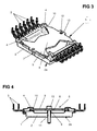
- the operation of the inventive fastening system is from the 3 and 4 easy to remove.
- These outer sections 10 are preferably at least partially positively received and act after attachment of the pressing element 5 elastically on the edge regions of the power module 1 with the receptacles 4 a.
- the pressing element 5 thus acts exclusively on the sections of the molded body 2 which are most strongly curved out of the ideal plane or the contact plane with the supporting structure or a heat sink, namely on the Corner areas.
- These areas of the power module 1 are locally limited with the hold down or contact force applied. It is thus possible to press the shaped body 2 into a planar shape, in which the underside of the shaped body 2 rests uniformly over the entire surface of the underside against the supporting structure.
- a more or even all lined up power modules 1 cross-pressing element 5a At least one fastening section 13 with a bore 12 for a connecting element 11 is provided in a region between two adjacent power modules 1.
- the contact pressure can be uniformly transmitted to the power modules 1.
- the moldings 2 can be positioned very close to each other.
- At least the edge regions 9, 10 of the contact pressure element 5 which come into contact with the power module 1 could be curved toward the power module 1, in order to increase the contact force when required.
- the contact pressure element 5 is completely flat and has, if at all, a curvature in the form of a deflection on the shaped body 2 of the power module 1 only after being clamped to the support structure.
- the central elevation 6 on the molded body 2 can be used as a spacer element and / or stop element, as in Fig. 4 is apparent.
- the sections formed on the contact pressure element 5 can be considered as be formed along an edge region of the power module 1, preferably an edge region with contact pins 3, extending edge strips. Preferably, these edge strips are located on two opposite sides of the pressing element 5 and thus also of the power module. 1
Landscapes
- Engineering & Computer Science (AREA)
- Microelectronics & Electronic Packaging (AREA)
- Cooling Or The Like Of Semiconductors Or Solid State Devices (AREA)
- Inverter Devices (AREA)
Abstract
Description
- Die Erfindung betrifft ein Befestigungssystem für ein Leistungsmodul nach dem Oberbegriff des Anspruchs 1. Weiter betrifft die Erfindung ein Leistungsmodul für die Verwendung mit einem derartigen Befestigungssystem nach dem Oberbegriff des Anspruchs 7 sowie ein Anpresselement zur Verwendung in einem derartigen Befestigungssystem, nach dem Oberbegriff des Anspruchs 10.
- Ein Leistungsmodul ist eine spezielle Art von integriertem Schaltkreis (IC), bei dem zwecks Steuerung von grossen Strömen und Spannungen entsprechend grosse Gehäuse, Transistoren und Dioden eingesetzt werden. Es besteht typischerweise aus einem Formkörper mit einer im Wesentlichen ebenen Fläche zur Anlage an eine Tragstruktur und einer Mehrzahl von aus dem Formkörper herausragenden Kontaktpins. Solche Leistungsmodule werden wegen der oftmals hohen Wärmeentwicklung typischerweise derart verbaut, dass die Wärme über eine beispielsweise ganzflächig metallisierte Anlagefläche und die Anschlüsse des Powersubstrates sowie je nach Bauform und Einsatzort gegebenenfalls über eine thermisch leitfähige Zwischenschicht an die Tragstruktur und/oder an einen Kühlkörper abgegeben wird. Mit Folien oder wärmeleitenden Pasten können kleinste Unebenheiten zwischen Leistungsmodul und Tragstruktur bzw. Kühlkörper ausgeglichen bzw. der Wärmewiderstand reduziert werden.
- Wie bei herkömmlichen ICs werden die Halbleiter-Chips in Leistungsmodulen mit Bonddrähten verdrahtet. In herkömmlichen Leistungsmodulen sind die Halbleiter-Chips und Bonddrähte mit einer weichen Silikonmasse eingegossen (molded). Technisch fortschrittlichere, als Moldmodul aufgebaute Leistungsmodule sind wie herkömmliche ICs hartvergossen. Aufgrund des Herstellungsprozesses ist die Rückseite der Moldmodule nun aber nicht perfekt eben, sondern ist von der Mitte her nach aussen etwas gekrümmt. Diese Krümmung kann durch Folien, Pasten oder dergleichen nicht mehr ausgeglichen werden, so dass die Leistungsmodule vielfach durch Anpresselemente gegen die Tragstruktur bzw. den Kühlkörper gepresst werden. Diese Anpresselemente sind typischerweise starre, meist längliche Platten, wobei zur Verteilung des Drucks und Vermeidung lokaler Druckspitzen Schaumstoffmatten zwischen Anpresselement und Leistungsmodul eingelegt werden müssen, was den Aufwand für die Bauteile als auch die Fertigung erheblich erhöht.
- Aufgabe der vorliegenden Erfindung ist es somit, ein Befestigungssystem für ein oder mehrere Leistungsmodule anzugeben, das unter Vermeidung der oben genannten Nachteile die sichere, einfache und betreffend des Wärmeübergangs vom Leistungsmodul auf die Tragestruktur optimierte Befestigung gewährleistet. Weitere Aufgaben der Erfindung sind ein zur Verwendung mit diesem Befestigungssystem optimiertes Leistungsmodul und/oder Anpresselement.
- Die erste Aufgabe wird durch die Merkmale des unabhängigen Anspruchs 1 gelöst. Die weiteren Aufgaben werden durch die Merkmale der unabhängigen Ansprüche 7 bzw. 10 gelöst. Vorteilhafte Weiterbildungen sind in den Figuren und in den abhängigen Patentansprüchen dargelegt.
- Gemäss der Erfindung sind am Anpresselement Abschnitte ausgeformt, deren äussere Randbereiche in befestigter Stellung von Leistungsmodul und Anpresselement elastisch auf Randbereiche des Leistungsmoduls einwirken und diese Randbereiche mit einer Anpresskraft beaufschlagen. Damit wird das Leistungsmodul ausschliesslich an den am stärksten aus der idealen Ebene des Gehäuses heraus gekrümmten Abschnitten, nämlich den Eckbereichen, mit der Niederhalte- bzw. Anpresskraft beaufschlagt. In den übrigen Bereichen bleibt das Modul frei und wird durch das Anpresselement nicht berührt, so dass keinerlei schützende Zwischenstücke, Matten od. dgl. vorgesehen sein müssen. Auch bietet das Anpresselement eine ausreichende Vorspannkraft auf das Gehäuse des Moduls, so dass auch aus dieser Hinsicht Matten zum Druckausgleich -wie bei starren Platten als Anpresselemente - nicht benötigt werden. Allein durch die Einwirkung auf die hochgekrümmten Ecken wird das Gehäuse des Moldmoduls zwischen dessen Tragstruktur und dem Anpresselement in eine ebene Form gebracht, in welcher es gleichmässig über die gesamte Fläche an der Tragstruktur aufliegt. So ist es einerseits gegen unerwünschte Bewegungen gesichert und andererseits ist der Wärmeübergang auf die Tragstruktur und/oder einen Kühlkörper über die maximal zur Verfügung stehende Fläche sichergestellt.
- Vorzugsweise sind Befestigungsabschnitte für je zumindest ein Verbindungselement an zwei gegenüberliegenden Randbereichen des Anpresselementes vorgesehen, vorzugsweise in einem kontaktpinfreien Randbereichen des Leistungsmoduls. Damit ist einerseits die Montage und Demontage des Anpresselements nicht durch die Kontaktpins behindert bzw. können diese im Rahmen der Montage bzw. Demontage nicht beschädigt werden. Überdies sind die Platzverhältnisse an den kontaktpinfreien Seiten bzw. Randbereichen des Leistungsmoduls am günstigsten für die Positionierung von Befestigungselementen.
- Gemäss einer weiteren bevorzugten Ausführungsform ist vorgesehen, dass die Befestigungsabschnitte am Anpresselement durch das Leistungsmodul überragende Laschen mit Bohrungen zur Aufnahme von Verbindungselementen, vorzugsweise in Form von Schrauben, gebildet sind. Diese Art der Befestigung ist einfach in der Fertigung, bei der Montage und auch der Demontage, etwa bei notwendigem Austausch des Leistungsmoduls.
- Eine einfach herzustellende und für die Montage und Demontage leicht zugängliche Variante sieht dabei vor, dass die am Anpresselement ausgeformten Abschnitte als vorzugsweise von einem zentralen Bereich des Anpresselementes ausgehende zungen- oder laschenförmige Abschnitte ausgebildet sind.
- Eine alternative Ausführungsform der Erfindung hingegen ist dadurch gekennzeichnet, dass die am Anpresselement ausgeformten Abschnitte als sich entlang eines Randbereiches des Leistungsmoduls erstreckenden Randstreifen ausgebildet sind, wodurch die Anpresskraft noch weiter verteilt und gleichmässiger auf das Leistungsmodul aufgebracht werden kann. Um dabei die Symmetrie der Krafteinwirkung zu gewährleisten, sind die die Anpresskraft aufbringenden Randbereiche vorzugsweise an zwei gegenüberliegenden Seiten des Anpresselementes angeordnet. Eine vorzugsweise Anordnung der die Anpresskraft aufbringenden Abschnitte in einem Randbereich mit Kontaktpins bietet den Vorteil, dass die Kontaktpins für die sichere Kontaktierung möglichst genau positioniert, sicher und unverschiebbar gehaltenden sind, zusätzlich zur verbesserten Anpresswirkung auf die Randbereiche des Leistungsmoduls.
- Eine vorteilhafte Ausführungsform des erfindungsgemässen Befestigungssystems in einer Variante für mehrere Leistungsmodule ist dadurch gekennzeichnet, dass das Anpresselement mehrere Leistungsmodule übergreift und zumindest ein Befestigungsabschnitt für zumindest ein Verbindungselement in einem Bereich zwischen zwei benachbarten Leistungsmodulen vorgesehen ist. Damit ist auch für eine Anordnung mehrerer, in einer Reihe hintereinander angeordneter Leistungsmodule die vorteilhafte sichere und die Leistungsmodule in ebene Form pressende Anbringung an einer Tragstruktur und/oder einem Kühlkörper möglich. Durch die Befestigung und damit auch die Möglichkeit der Einbringung der Anpresskraft zwischen zwei benachbarten Leistungsmodulen kann für alle Leistungsmodule die gleiche Anpresswirkung gewährleistet werden, ohne dass einzelne Leistungsmodule zu stark beaufschlagt und damit vielleicht beschädigt werden können. Andererseits wird dadurch auch eine zu geringe Anpresswirkung auf einzelne, insbesondere die in der Mitte der Reihe liegenden Leistungsmodule vermieden.
- Ein Leistungsmodul für die Verwendung mit einem Befestigungssystem nach einem der obigen Absätze besteht typischerweise aus einem Formkörper mit einer im Wesentlichen ebenen Fläche zur Anlage an eine Tragstruktur und einer Mehrzahl von aus dem Formkörper herausragenden Kontaktpins. Zur Lösung der eingangs gestellten Aufgabe ist das Leistungsmodul dadurch gekennzeichnet, dass Aufnahmen für Abschnitte eines Anpresselementes im Randbereich des Formkörpers vorgesehen sind. Bei Leistungsmodulen mit eckigem Formkörper sind diese Aufnahmen vorzugsweise an zumindest symmetrisch um das Zentrum des Formkörpers verteilten Ecken des Leistungsmoduls vorgesehen. Damit lassen sich ein möglichst gleichmässige Krafteinleitung in das Leistungsmodul und die gleichmässige Anpresswirkung an die Tragstruktur erzielen.
- Bei einer vorteilhaften Ausführungsform des Leistungsmoduls sind die Aufnahmen erhöht in Bezug auf den zentralen Bereich des Formkörpers angeordnet, der gegebenenfalls mit einer weiteren Erhöhung versehen ist, welche vorzugsweise zentrale Erhöhung in Bezug auf den zentralen Bereich des Formkörpers maximal die Höhe der Aufnahmen erreicht. Durch diese geometrische Gestaltung werden alle Bereiche des Formkörpers freigehalten von Berührungen und damit vor Beschädigung durch das Anpresselement geschützt, ausser den Bereichen, in welchen das Anpresselement die optimale Wirkung auf den Formkörper ausüben kann. Eine zentrale Erhöhung am Formkörper andererseits kann als Sicherheitsanschlag gegen zu starkes Vorspannen des Anpresselementes bei der Anordnung des Leistungsmoduls an der Tragstruktur dienen, so dass die Anpresskraft begrenzt ist, um eine Beschädigung des Formkörpers und/oder des Befestigungssystems zu vermeiden.
- Um eine platzsparende Anbringung des Befestigungssystems zu gewährleisten weist der Formkörper vorteilhaft zumindest eine Ausnehmung oder Durchgangsöffnung im kontaktpinfreien Randbereich und/oder eine Durchgangsöffnung innerhalb der Randbereiche auf.
- Ein erfindungsgemässes Anpresselement zur Verwendung in einem Befestigungssystem wie oben beschrieben ist gekennzeichnet durch äussere Abschnitte, deren äussere Randbereiche in befestigter Stellung von Leistungsmodul und Anpresselement elastisch auf Randbereiche des Leistungsmoduls einwirken. Damit kann die Anpresswirkung und Anpressrichtung bis zu einem gewissen Grad von der Befestigung des Anpresselementes entkoppelt werden und es können vor allem die Angriffspunkte der Anpresskraft unabhängig von den Befestigungspunkten gewählt werden.
- Zumindest die mit dem Leistungsmodul in Kontakt kommenden Randbereiche einer weiteren erfindungsgemässen Ausführungsform des Anpresselementes sind auf das Leistungsmodul hin gekrümmt. Dadurch kann bei Bedarf die erzielbare Anpresskraft gesteigert werden.
- Eine weitere Ausführungsform eines erfindungsgemässen Anpresselementes ist dadurch gekennzeichnet, dass die am Anpresselement ausgeformten Abschnitte als sich entlang eines Randbereiches des Leistungsmodul erstreckenden Randstreifen ausgebildet sind. Vorzugsweise liegen diese Randstreifen an zwei gegenüberliegenden Seiten des Anpresselementes, um damit eine gleichmässig verteilte Krafteinleitung in den Formkörper des Leistungsmoduls zu erzielen. Die Abschnitte des Anpresselementes liegen alternativ oder zusätzlich zum vorstehenden Merkmal vorzugsweise in einem Randbereich mit Kontaktpins. Dadurch werden diese Kontaktpins sicher, unverschiebbar und in einer genau definierten Position gehalten.
- Weitere Vorteile, Merkmale und Einzelheiten der Erfindung ergeben sich aus der nachfolgenden Beschreibung, in der unter Bezugnahme auf die Zeichnungen Ausführungsbeispiele der Erfindung beschrieben sind. Dabei können die in den Ansprüchen und in der Beschreibung erwähnten Merkmale jeweils einzeln für sich oder in beliebiger Kombination erfindungswesentlich sein.
- Die Bezugszeichenliste ist Bestandteil der Offenbarung. Die Figuren werden zusammenhängend und übergreifend beschrieben. Gleiche Bezugszeichen bedeuten gleiche Bauteile, Bezugszeichen mit unterschiedlichen Indices geben funktionsgleiche oder ähnliche Bauteile an.
- Es zeigen dabei:
- Fig. 1
- ein Leistungsmodul in einer bevorzugten Ausführungsform zur Verwendung mit dem erfindungsgemässen Befestigungssystem in perspektivischer Ansicht,
- Fig. 2
- ein Anpresselement in einer bevorzugten Ausführungsform zur Verwendung mit dem erfindungsgemässen Befestigungssystem in perspektivischer Ansicht,
- Fig. 3
- das Leistungsmodul der
Fig. 1 und das Anpresselement derFig. 2 in zusammenwirkender Anordnung im Rahmen des erfindungsgemässen Befestigungssystems, - Fig. 4
- eine Seitenansicht der Anordnung der
Fig. 3 aus einer Richtung parallel zu den Randbereichen mit den Kontaktpins, und - Fig. 5
- eine perspektivische Ansicht einer Anordnung von mehreren Leistungsmodulen mit einem gemeinsamen erfindungsgemässen Anpresselement.
-
Fig. 1 zeigt ein Leistungsmodul 1 mit einem Formkörper 2 und von der im Formkörper 2 typischerweise vergossenen Schaltung nach aussen führenden und vorzugsweise gleich grossen Kontaktpins 3. Für grosse Ströme können zwei oder mehrere Kontaktpins 3 auch parallel geschaltet werden, oder es können Kontaktpins 3 ausgelassen werden zur Erhöhung der Luft- und Kriechstrecken. Im Inneren des Formkörpers 2 sind die Halbleiter-Chips mit Bonddrähten verdrahtet und entweder mit einer weichen Silikonmasse vergossen oder bei technisch fortschrittlicheren, als Moldmodule ausgebildeten Leistungsmodulen 1 hartvergossen. Durch den harten Verguss können die Bonddrähte nicht mehr wackeln, somit gibt es keine Ermüdungsbrüche und das Vibrationsproblem ist beseitigt. - Die Kontaktpins 3 sind vorzugsweise als Einpresspins ausgebildet, bei welchen keinerlei Zinndurchstiegsprobleme wie bei hochbestromten, bleifrei gelöteten Pins auftreten. Die Kontaktpins 3 liegen vorzugsweise in zwei versetzten Reihen, um trotz der kompakten Bauweise (Pinabstand z. B. nur 3 mm) ausreichende Abstände realisieren zu können. So kann das Leistungsmodul 1 auch für höhere Spannungen eingesetzt werden
- Derartige Leistungsmodule weisen eine deutlich gesteigerte Zuverlässigkeit sowie Lebensdauer gegenüber herkömmlichen Leistungsmodulen auf.
- Aufgrund der reduzierten Komplexität des inneren Aufbaus und Herstellprozesses sind derartige Leistungsmodule auch einfacher und günstiger zu fertigen. Vorzugsweise ist dabei die Bauform des Formkörpers 2 und die Anordnung der Kontaktpins 3 für alle Varianten des Leistungsmoduls 1 gleich, so dass eine Art "generisches Gehäuse" geschaffen ist. Bauform und Lage der Anschlüsse ist immer gleich und das Innenleben kann je nach Aufgabenstellung und Einsatzzweck angepasst werden.
- Ein spezielles Problem bei den bislang bekannten Leistungsmodulen ist deren Befestigung, die fast jedes Mal individuell gelöst werden musste. Hier greift das erfindungsgemässe Befestigungssystem und bietet eine neue, vorteilhafte Lösung.
- Wie in
Fig. 1 zu erkennen ist, ist ein mit dem erfindungsgemässen Befestigungssystem zu verwendendes Leistungsmodul 1 mit einem Formkörper 2 versehen, der mit einer im Wesentlichen ebenen Anlagefläche 2a zur Anlage an eine Tragstruktur ausgebildet ist. An der der Tragestruktur - oder auch an einem Kühlkörper oder dergleichen - gegenüberliegenden Seite des Formkörpers 2 sind Aufnahmen 4 für Abschnitte eines Anpresselementes 5 (sieheFig. 2 ) typischerweise im Randbereich des Formkörpers 2 vorgesehen. Bei Leistungsmodulen 1 mit eckigem Formkörper 2 - wie jenem inFig. 1 - sind diese Aufnahmen 4 vorzugsweise an zumindest symmetrisch um das Zentrum des Formkörpers 2 verteilten Ecken des Leistungsmoduls 1 angeordnet. - Die Aufnahmen 4 sind dabei vorzugsweise erhöht in Bezug auf den zentralen Bereich des Formkörpers 2 angeordnet. Gegebenenfalls ist vorzugsweise im zentralen Bereich des Formkörpers eine weitere Erhöhung 6 angeordnet. Diese erreicht dabei in Bezug auf den zentralen Bereich des Formkörpers 2 vorzugsweise maximal die Höhe der Aufnahmen 4. Um die Symmetrie der Krafteinleitung durch das Anpresselement 5 in den Formkörper 2 möglichst nicht negativ zu beeinflussen, ist typischerweise die weitere Erhöhung 5 zentral am Formkörper 2 angeordnet.
- Schliesslich kann der Formkörper 2 noch mit zumindest einer Ausnehmung 7 am äusseren kontaktpinfreien Randbereich versehen sein, beispielsweise in Form einer halbrunden, nach aussen hin offenen Nut oder Ausfräsung. Vorzugsweise ebenfalls im kontaktpinfreien Randbereich des Formkörpers 2, allenfalls, wenn das die Anordnung der Halbleiter-Chips im Inneren des Formkörpers 2 gestattet, könnte auch eine Durchgangsöffnung mit vorzugsweise kreisförmigem Querschnitt zur Hindurchführung von vorzugsweise Befestigungselementen oder dergleichen vorhanden sein.
-
Fig. 2 zeigt ein erfindungsgemässes Anpresselement 5 zur Verwendung in einem Befestigungssystem für Leistungsmodule 1 wie oben beschrieben. Es weist von einem zentralen Bereich 8 ausgehende äussere Abschnitte 9 auf. Diese Abschnitte 9 gehen in äussere Randbereiche 10 über, die in einer derartigen geometrischen Anordnung - vorzugsweise spiegel- oder punktsymmetrisch um eine Achse bzw. das Zentrum des Anpresselementes 5 - vorliegen, dass sie bei Auflegen des Anpresselementes 5 auf das Leistungsmodul 1 in die Aufnahmen 4 des Formkörpers 2 zu liegen kommen. Wenn dann das Anpresselement 5 durch geeignete Verbindungselemente 11 (sieheFig. 4 ), wie beispielsweise Schrauben, in Richtung auf das Leistungsmodul 1 bzw. der darunter liegenden Tragstruktur hin mit einer Kraft beaufschlagt wird, werden die Randbereiche 10 gegen die Aufnahmen 4 gepresst und bewirken eine durch die Aufnahmen 4 auf die Tragstruktur hin gerichtete Anpresskraft auf das Leistungsmodul 1. Die Krafteinwirkung erfolgt dabei in elastischer Weise. Durch die genaue Form und Ausrichtung der nach aussen weisenden Abschnitte 9 und der äusseren Randbereiche 10 des Anpresselementes 5 können die Anpresswirkung und die Anpressrichtung bis zu einem gewissen Grad von der Befestigung des Anpresselementes 5 entkoppelt und die Angriffspunkte der Anpresskraft unabhängig von den Befestigungspunkten gewählt werden. - Zur Befestigung des Anpresselementes 5 an der Tragstruktur oder einem Kühlkörper oder dergleichen mittels der bereits genannten Verbindungselemente 11 sind an den Rändern des Anpresselementes 5, vorzugsweise jenen Rändern, die parallel zu den kontaktpinfreien Rändern der Leistungsmoduls 1 verlaufen, Ausnehmungen zum Einsetzen des Verbindungselementes 11 oder vorzugsweise Durchgangsöffnungen 12 mit vorzugsweise kreisförmigem Querschnitt angeordnet. Vorzugsweise gehen dafür Befestigungsabschnitte 13, vorteilhafterweise in Form von Laschen oder Zungen, vom zentralen Bereich 8 des Anpresselementes 5 aus, vorzugsweise für je zumindest ein Verbindungselement 11 an den zwei gegenüberliegenden Randbereichen des Anpresselementes 5. Vorteilhafterweise sind die Durchgangsöffnungen 12 des Anpresselements 5 in diesen Befestigungsabschnitten 13 derart positioniert, dass das Verbindungselement 11 durch die Ausnehmung 7 des Formkörpers 2 verläuft.
- Die Wirkungsweise des erfindungsgemässen Befestigungssystems ist aus den
Fig. 3 und 4 einfach zu entnehmen. Die äusseren Abschnitte 10 des Anpresselementes 5, das den Formkörper 2 des Leistungsmoduls 1 überdeckend auf dessen Oberseite aufgelegt ist, greifen in die Aufnahmen 4 des Formkörpers 2 ein. Diese äusseren Abschnitte 10 sind dort vorzugsweise zumindest teilweise formschlüssig aufgenommen und wirken nach Befestigung des Anpresselementes 5 elastisch auf die Randbereiche des Leistungsmoduls 1 mit den Aufnahmen 4 ein. Das Anpresselement 5 wirkt derart ausschliesslich an den am stärksten aus der idealen Ebene bzw. der Kontakteebene mit der Tragstruktur oder einem Kühlkörper heraus gekrümmten Abschnitten des Formkörpers 2 ein, nämlich an den Eckbereichen. Diese Bereiche des Leistungsmoduls 1 werden lokal begrenzt mit der Niederhalte- bzw. Anpresskraft beaufschlagt. Derart ist es möglich, den Formkörper 2 in eine ebene Form zu drücken, in der die Unterseite des Formkörpers 2 gleichmässig über die gesamte Fläche der Unterseite an der Tragstruktur aufliegt. - Für eine Anordnung von mehreren Leistungsmodulen 1, die in einer geraden Reihe hintereinander, mit den Reihen der Kontaktpins 3 ebenfalls in gerader Linie hintereinander, vorliegen, kann ein mehrere oder sogar alle aufgereihten Leistungsmodule 1 übergreifendes Anpresselement 5a vorgesehen sein. Zumindest ein Befestigungsabschnitt 13 mit einer Bohrung 12 für ein Verbindungselement 11 ist in einem Bereich zwischen zwei benachbarten Leistungsmodulen 1 vorgesehen. Damit kann die Anpresswirkung gleichmässig auf die Leistungsmodule 1 übertragen werden. Bei Ausgestaltung der Leistungsmodule 1 mit den Ausnehmungen 7 oder Durchgangsöffnungen für die Verbindungselemente 11 können die Formkörper 2 sehr eng aneinander liegend positioniert werden.
- Zumindest die mit dem Leistungsmodul 1 in Kontakt kommenden Randbereiche 9, 10 des Anpresselementes 5 könnten auf das Leistungsmodul 1 hin gekrümmt sein, um dadurch bei Bedarf die Anpresskraft zu steigern. Typischerweise ist aber das Anpresselement 5 komplett flach und weist, wenn überhaupt, nur nach dem Verspannen mit der Tragstruktur eine Krümmung in Form einer Durchbiegung auf den Formkörper 2 des Leistungsmoduls 1 hin auf. Um diese Durchbiegung aber zu begrenzen und damit auch die maximale Anpresskraft zu begrenzen und das Anpresselement 5 vom Formkörper 2 möglichst beabstandet zu halten, kann die zentrale Erhebung 6 am Formkörper 2 als Abstandselement und/oder Anschlagselement genutzt werden, wie in
Fig. 4 ersichtlich ist. - Anstelle der zungen- oder laschenförmigen Abschnitte 9, 10 des Anpresselementes 5 können gemäss einer anderen erfindungsgemässen Ausführungsform die am Anpresselement 5 ausgeformten Abschnitte als sich entlang eines Randbereiches des Leistungsmoduls 1, vorzugsweise einem Randbereich mit Kontaktpins 3, erstreckenden Randstreifen ausgebildet sein. Vorzugsweise liegen diese Randstreifen an zwei gegenüberliegenden Seiten des Anpresselementes 5 und damit auch des Leistungsmoduls 1.
-
- 1
- Leistungsmodul
- 2
- Formkörper
- 2a
- Kontaktfläche
- 3
- Kontaktpins
- 4
- Aufnahme
- 5
- Anpresselement
- 6
- Zentrale Erhebung
- 7
- Ausnehmung
- 8
- Zentraler Bereich
- 9
- Äusserer Abschnitt
- 10
- Äusserer Randbereich
- 11
- Verbindungselement
- 12
- Bohrung
- 13
- Befestigungsabschnitt
Claims (12)
- Befestigungssystem für ein Leistungsmodul (1), bestehend aus einem Formkörper (2) mit einer im Wesentlichen ebenen Anlagefläche (2a) zur Anlage an eine Tragstruktur und einer Mehrzahl von aus dem Formkörper (2) herausragenden Kontaktpins (3), mit einem Anpresselement (5) für das Leistungsmodul (1), das auf einer der Anlagefläche (2a) gegenüberliegenden Seite des Leistungsmoduls (1) vorgesehen ist, und mit zumindest einem Verbindungselement (11) zur Befestigung des Anpresselementes (5) an der Tragstruktur und zur Beaufschlagung des Anpresselementes (5) mit einer Anpresskraft auf die Anlagefläche (2a) hin, gekennzeichnet durch am Anpresselement (5) ausgeformte Abschnitte (9, 10), deren äussere Randbereiche (10) in befestigter Stellung von Leistungsmodul (1) und Anpresselement (5) elastisch auf Randbereiche des Leistungsmoduls (1) einwirken und diese Randbereiche mit einer Anpresskraft beaufschlagen.
- Befestigungssystem nach Anspruch 1, dadurch gekennzeichnet, dass Befestigungsabschnitte (13) für je zumindest ein Verbindungselement (11) an zwei gegenüberliegenden Randbereichen des Anpresselementes (5) vorgesehen sind, vorzugsweise in einem kontaktpinfreien Randbereichen des Leistungsmoduls (1).
- Befestigungssystem nach Anspruch 2, dadurch gekennzeichnet, dass die Befestigungsabschnitte (13) am Anpresselement (5) durch das Leistungsmodul (1) überragende Laschen mit Bohrungen (12) zur Aufnahme von Verbindungselementen (11), vorzugsweise Schrauben, gebildet sind.
- Befestigungssystem nach einem der Ansprüche 1 bis 3, dadurch gekennzeichnet, dass die am Anpresselement (5) ausgeformten Abschnitte (9, 10) als vorzugsweise von einem zentralen Bereich (8) des Anpresselementes (5) ausgehende zungen- oder laschenförmige Abschnitte ausgebildet sind.
- Befestigungssystem nach einem der Ansprüche 1 bis 3, dadurch gekennzeichnet, dass die am Anpresselement (5) ausgeformten Abschnitte als sich entlang eines Randbereiches des Leistungsmoduls (1), vorzugsweise einem Randbereich mit Kontaktpins (3), erstreckenden Randstreifen ausgebildet sind, vorzugsweise an zwei gegenüberliegenden Seiten des Anpresselementes (5).
- Befestigungssystem nach einem der Ansprüche 1 bis 5, für mehrere Leistungsmodule (1), dadurch gekennzeichnet, dass das Anpresselement (5a) mehrere Leistungsmodule (1) übergreift und zumindest ein Befestigungsabschnitt (13) für zumindest ein Verbindungselement (11) in einem Bereich zwischen zwei benachbarten Leistungsmodulen (1) vorgesehen ist.
- Leistungsmodul (1) für die Verwendung mit einem Befestigungssystem nach einem der Ansprüche 1 bis 6, bestehend aus einem Formkörper (2) mit einer im Wesentlichen ebenen Anlagefläche (2a) zur Anlage an eine Tragstruktur und einer Mehrzahl von aus dem Formkörper (2) herausragenden Kontaktpins (3), gekennzeichnet durch Aufnahmen (4) für Abschnitte (10) eines Anpresselementes (5) im Randbereich des Formkörpers (2), bei Leistungsmodulen mit eckigem Formkörper (2) vorzugsweise an zumindest symmetrisch um das Zentrum des Formkörpers (2) verteilten Ecken des Leistungsmoduls (1).
- Leistungsmodul nach Anspruch 7, dadurch gekennzeichnet, dass die Aufnahmen (4) erhöht in Bezug auf den zentralen Bereich des Formkörpers (2) angeordnet sind, der gegebenenfalls mit einer weiteren Erhöhung (6) versehen ist, welche vorzugsweise zentrale Erhöhung (6) in Bezug auf den zentralen Bereich des Formkörpers (2) maximal die Höhe der Aufnahmen (4) erreicht.
- Leistungsmodul nach einem der Ansprüche 7 oder 8, dadurch gekennzeichnet, dass der Formkörper (2) zumindest eine Ausnehmung (7) oder Durchgangsöffnung in einem kontaktpinfreien Randbereich des Formkörpers (2) und/oder eine Durchgangsöffnung innerhalb der Randbereiche des Formkörpers (2) aufweist.
- Anpresselement (5) zur Verwendung in einem Befestigungssystem nach einem der Ansprüche 1 bis 6, gekennzeichnet durch äussere Abschnitte (9), deren äussere Randbereiche (10) in befestigter Stellung von Leistungsmodul (1) und Anpresselement (5) elastisch auf Randbereiche des Leistungsmoduls (1) einwirken.
- Anpresselement nach Anspruch 10, dadurch gekennzeichnet, dass zumindest die mit dem Leistungsmodul (1) in Kontakt kommenden Randbereiche (9, 10) auf das Leistungsmodul (1) hin gekrümmt sind.
- Anpresselement nach einem der Ansprüche 10 oder 11, dadurch gekennzeichnet, dass die am Anpresselement (5) ausgeformten Abschnitte als sich entlang eines Randbereiches des Leistungsmoduls (1), vorzugsweise einem Randbereich mit Kontaktpins (3), erstreckenden Randstreifen ausgebildet sind, vorzugsweise an zwei gegenüberliegenden Seiten des Anpresselementes (5).
Priority Applications (2)
| Application Number | Priority Date | Filing Date | Title |
|---|---|---|---|
| EP14163131.7A EP2927954B1 (de) | 2014-04-02 | 2014-04-02 | Befestigungssystem für ein Leistungsmodul |
| US14/676,858 US9497876B2 (en) | 2014-04-02 | 2015-04-02 | Fastening systems for power modules |
Applications Claiming Priority (1)
| Application Number | Priority Date | Filing Date | Title |
|---|---|---|---|
| EP14163131.7A EP2927954B1 (de) | 2014-04-02 | 2014-04-02 | Befestigungssystem für ein Leistungsmodul |
Publications (2)
| Publication Number | Publication Date |
|---|---|
| EP2927954A1 true EP2927954A1 (de) | 2015-10-07 |
| EP2927954B1 EP2927954B1 (de) | 2021-06-09 |
Family
ID=50792349
Family Applications (1)
| Application Number | Title | Priority Date | Filing Date |
|---|---|---|---|
| EP14163131.7A Active EP2927954B1 (de) | 2014-04-02 | 2014-04-02 | Befestigungssystem für ein Leistungsmodul |
Country Status (2)
| Country | Link |
|---|---|
| US (1) | US9497876B2 (de) |
| EP (1) | EP2927954B1 (de) |
Cited By (2)
| Publication number | Priority date | Publication date | Assignee | Title |
|---|---|---|---|---|
| US9497876B2 (en) | 2014-04-02 | 2016-11-15 | Brusa Elektronik Ag | Fastening systems for power modules |
| CN106572621A (zh) * | 2016-11-10 | 2017-04-19 | 广东高标电子科技有限公司 | 控制器以及具有该控制器的电动车 |
Citations (7)
| Publication number | Priority date | Publication date | Assignee | Title |
|---|---|---|---|---|
| JPS5999743A (ja) * | 1982-11-30 | 1984-06-08 | Nissan Motor Co Ltd | 集積回路パツケ−ジ |
| EP0785575A2 (de) * | 1996-01-17 | 1997-07-23 | Mitsubishi Denki Kabushiki Kaisha | Halbleiter und Halbleitermodul |
| JP2004087552A (ja) * | 2002-08-23 | 2004-03-18 | Mitsubishi Electric Corp | 半導体装置 |
| EP1536467A2 (de) * | 2003-11-28 | 2005-06-01 | Kabushiki Kaisha Toshiba | Halter und Wärmeleiter für Elektroniktbauteil |
| US20090168358A1 (en) * | 2007-12-26 | 2009-07-02 | Keihin Corporation | Power drive unit |
| FR2931523A1 (fr) * | 2008-05-21 | 2009-11-27 | Fagorbrandt Sas | Dispositif de fixation de composants et appareil electromenager associe |
| JP2011035265A (ja) * | 2009-08-04 | 2011-02-17 | Mitsubishi Electric Corp | 半導体装置 |
Family Cites Families (6)
| Publication number | Priority date | Publication date | Assignee | Title |
|---|---|---|---|---|
| JPS5963735A (ja) | 1982-10-05 | 1984-04-11 | Rohm Co Ltd | 半導体装置の製造方法 |
| DE59406013D1 (de) * | 1993-06-07 | 1998-06-25 | Melcher Ag | Befestigungsvorrichtung für halbleiter-schaltelemente |
| US20060139890A1 (en) * | 2004-12-23 | 2006-06-29 | A-Sheng Liu | Fastening device II |
| DE102007020618B8 (de) | 2007-04-30 | 2009-03-12 | Danfoss Silicon Power Gmbh | Verfahren zum Herstellen eines festen Leistungsmoduls und damit hergestelltes Transistormodul |
| JP4643703B2 (ja) * | 2008-11-21 | 2011-03-02 | 株式会社東芝 | 半導体装置の固定具及びその取付構造 |
| EP2927954B1 (de) | 2014-04-02 | 2021-06-09 | Brusa Elektronik AG | Befestigungssystem für ein Leistungsmodul |
-
2014
- 2014-04-02 EP EP14163131.7A patent/EP2927954B1/de active Active
-
2015
- 2015-04-02 US US14/676,858 patent/US9497876B2/en active Active
Patent Citations (7)
| Publication number | Priority date | Publication date | Assignee | Title |
|---|---|---|---|---|
| JPS5999743A (ja) * | 1982-11-30 | 1984-06-08 | Nissan Motor Co Ltd | 集積回路パツケ−ジ |
| EP0785575A2 (de) * | 1996-01-17 | 1997-07-23 | Mitsubishi Denki Kabushiki Kaisha | Halbleiter und Halbleitermodul |
| JP2004087552A (ja) * | 2002-08-23 | 2004-03-18 | Mitsubishi Electric Corp | 半導体装置 |
| EP1536467A2 (de) * | 2003-11-28 | 2005-06-01 | Kabushiki Kaisha Toshiba | Halter und Wärmeleiter für Elektroniktbauteil |
| US20090168358A1 (en) * | 2007-12-26 | 2009-07-02 | Keihin Corporation | Power drive unit |
| FR2931523A1 (fr) * | 2008-05-21 | 2009-11-27 | Fagorbrandt Sas | Dispositif de fixation de composants et appareil electromenager associe |
| JP2011035265A (ja) * | 2009-08-04 | 2011-02-17 | Mitsubishi Electric Corp | 半導体装置 |
Cited By (3)
| Publication number | Priority date | Publication date | Assignee | Title |
|---|---|---|---|---|
| US9497876B2 (en) | 2014-04-02 | 2016-11-15 | Brusa Elektronik Ag | Fastening systems for power modules |
| CN106572621A (zh) * | 2016-11-10 | 2017-04-19 | 广东高标电子科技有限公司 | 控制器以及具有该控制器的电动车 |
| CN106572621B (zh) * | 2016-11-10 | 2018-12-21 | 广东高标电子科技有限公司 | 控制器以及具有该控制器的电动车 |
Also Published As
| Publication number | Publication date |
|---|---|
| EP2927954B1 (de) | 2021-06-09 |
| US20150289404A1 (en) | 2015-10-08 |
| US9497876B2 (en) | 2016-11-15 |
Similar Documents
| Publication | Publication Date | Title |
|---|---|---|
| DE69632865T2 (de) | Transistor-lötclip und kühlkörper | |
| DE112007002446B4 (de) | Elektronische Schaltungsvorrichtung und Verfahren zu ihrer Herstellung | |
| DE102016102188B4 (de) | Kühlkörperanordnung | |
| DE10324909B4 (de) | Gehäuse für ein strahlungsemittierendes Bauelement, Verfahren zu dessen Herstellung und strahlungsemittierendes Bauelement | |
| DE102009002992B4 (de) | Leistungshalbleitermodulanordnung mit eindeutig und verdrehsicher auf einem Kühlkörper montierbarem Leistungshalbleitermodul und Montageverfahren | |
| DE102015115122B4 (de) | Leistungshalbleitermodul mit zweiteiligem Gehäuse | |
| DE102012201172B4 (de) | Verfahren zur Herstellung eines Leistungshalbleitermoduls mit geprägter Bodenplatte | |
| DE10129388A1 (de) | Elektronisches Bauteil und Verfahren zu seiner Herstellung | |
| DE102011089539B3 (de) | Vorrichtung zur Ansteuerung einer elektrischen Heizung für Fahrzeuge und elektrische Heizung mit einer derartigen Vorrichtung | |
| DE10149886A1 (de) | Leistunghalbleitermodul | |
| EP2236928A1 (de) | Hitzeschildelement eines Hitzeschildes | |
| DE202020106131U1 (de) | Ein Steuerchip-Sockel für Steuerungssysteme | |
| DE102006045939A1 (de) | Leistungshalbleitermodul mit verbesserter Temperaturwechselstabilität | |
| EP2927954B1 (de) | Befestigungssystem für ein Leistungsmodul | |
| DE102016220555B4 (de) | Kühlkörperbefestigungssystem und -verfahren | |
| DE102016207528A1 (de) | Hochfrequenz-Hochleistungsvorrichtung | |
| DE102014216170B3 (de) | Elektronikmodul | |
| DE202011050739U1 (de) | System zum Befestigen einer Schiene auf einem Untergrund | |
| WO2000003575A1 (de) | Fadenbearbeitungssystem | |
| EP3499563B1 (de) | Leistungshalbleitermodul und verfahren zur kraftschlüssigen anordnung eines leistungshalbleitermoduls | |
| DE29511775U1 (de) | Anordnung mit einer Leiterplatte | |
| DE102017218875B4 (de) | Leistungsmodul-Baugruppe | |
| DE19543260A1 (de) | Elektrische Bauelementeanordnung mit mehreren in einem Gehäuse angeordneten elektrischen Bauelementen | |
| WO2005053366A1 (de) | Elektrische schaltungsanordnung | |
| DE102012219145A1 (de) | Elektronikanordnung mit reduzierter Toleranzkette |
Legal Events
| Date | Code | Title | Description |
|---|---|---|---|
| PUAI | Public reference made under article 153(3) epc to a published international application that has entered the european phase |
Free format text: ORIGINAL CODE: 0009012 |
|
| AK | Designated contracting states |
Kind code of ref document: A1 Designated state(s): AL AT BE BG CH CY CZ DE DK EE ES FI FR GB GR HR HU IE IS IT LI LT LU LV MC MK MT NL NO PL PT RO RS SE SI SK SM TR |
|
| AX | Request for extension of the european patent |
Extension state: BA ME |
|
| 17P | Request for examination filed |
Effective date: 20160316 |
|
| RBV | Designated contracting states (corrected) |
Designated state(s): AL AT BE BG CH CY CZ DE DK EE ES FI FR GB GR HR HU IE IS IT LI LT LU LV MC MK MT NL NO PL PT RO RS SE SI SK SM TR |
|
| STAA | Information on the status of an ep patent application or granted ep patent |
Free format text: STATUS: EXAMINATION IS IN PROGRESS |
|
| 17Q | First examination report despatched |
Effective date: 20161115 |
|
| REG | Reference to a national code |
Ref country code: DE Ref legal event code: R079 Ref document number: 502014015649 Country of ref document: DE Free format text: PREVIOUS MAIN CLASS: H01L0023400000 Ipc: H01L0023000000 |
|
| RIC1 | Information provided on ipc code assigned before grant |
Ipc: H01L 23/40 20060101ALI20191126BHEP Ipc: H01L 23/00 20060101AFI20191126BHEP Ipc: H05K 7/02 20060101ALI20191126BHEP Ipc: H01L 25/065 20060101ALI20191126BHEP Ipc: H01L 25/11 20060101ALI20191126BHEP Ipc: H01L 23/31 20060101ALI20191126BHEP |
|
| GRAP | Despatch of communication of intention to grant a patent |
Free format text: ORIGINAL CODE: EPIDOSNIGR1 |
|
| STAA | Information on the status of an ep patent application or granted ep patent |
Free format text: STATUS: GRANT OF PATENT IS INTENDED |
|
| INTG | Intention to grant announced |
Effective date: 20210122 |
|
| GRAS | Grant fee paid |
Free format text: ORIGINAL CODE: EPIDOSNIGR3 |
|
| GRAA | (expected) grant |
Free format text: ORIGINAL CODE: 0009210 |
|
| STAA | Information on the status of an ep patent application or granted ep patent |
Free format text: STATUS: THE PATENT HAS BEEN GRANTED |
|
| AK | Designated contracting states |
Kind code of ref document: B1 Designated state(s): AL AT BE BG CH CY CZ DE DK EE ES FI FR GB GR HR HU IE IS IT LI LT LU LV MC MK MT NL NO PL PT RO RS SE SI SK SM TR |
|
| REG | Reference to a national code |
Ref country code: GB Ref legal event code: FG4D Free format text: NOT ENGLISH |
|
| REG | Reference to a national code |
Ref country code: CH Ref legal event code: EP Ref country code: AT Ref legal event code: REF Ref document number: 1401188 Country of ref document: AT Kind code of ref document: T Effective date: 20210615 |
|
| REG | Reference to a national code |
Ref country code: DE Ref legal event code: R096 Ref document number: 502014015649 Country of ref document: DE |
|
| REG | Reference to a national code |
Ref country code: IE Ref legal event code: FG4D Free format text: LANGUAGE OF EP DOCUMENT: GERMAN |
|
| REG | Reference to a national code |
Ref country code: LT Ref legal event code: MG9D |
|
| PG25 | Lapsed in a contracting state [announced via postgrant information from national office to epo] |
Ref country code: LT Free format text: LAPSE BECAUSE OF FAILURE TO SUBMIT A TRANSLATION OF THE DESCRIPTION OR TO PAY THE FEE WITHIN THE PRESCRIBED TIME-LIMIT Effective date: 20210609 Ref country code: FI Free format text: LAPSE BECAUSE OF FAILURE TO SUBMIT A TRANSLATION OF THE DESCRIPTION OR TO PAY THE FEE WITHIN THE PRESCRIBED TIME-LIMIT Effective date: 20210609 Ref country code: BG Free format text: LAPSE BECAUSE OF FAILURE TO SUBMIT A TRANSLATION OF THE DESCRIPTION OR TO PAY THE FEE WITHIN THE PRESCRIBED TIME-LIMIT Effective date: 20210909 Ref country code: HR Free format text: LAPSE BECAUSE OF FAILURE TO SUBMIT A TRANSLATION OF THE DESCRIPTION OR TO PAY THE FEE WITHIN THE PRESCRIBED TIME-LIMIT Effective date: 20210609 |
|
| REG | Reference to a national code |
Ref country code: NL Ref legal event code: MP Effective date: 20210609 |
|
| PG25 | Lapsed in a contracting state [announced via postgrant information from national office to epo] |
Ref country code: NO Free format text: LAPSE BECAUSE OF FAILURE TO SUBMIT A TRANSLATION OF THE DESCRIPTION OR TO PAY THE FEE WITHIN THE PRESCRIBED TIME-LIMIT Effective date: 20210909 Ref country code: RS Free format text: LAPSE BECAUSE OF FAILURE TO SUBMIT A TRANSLATION OF THE DESCRIPTION OR TO PAY THE FEE WITHIN THE PRESCRIBED TIME-LIMIT Effective date: 20210609 Ref country code: SE Free format text: LAPSE BECAUSE OF FAILURE TO SUBMIT A TRANSLATION OF THE DESCRIPTION OR TO PAY THE FEE WITHIN THE PRESCRIBED TIME-LIMIT Effective date: 20210609 Ref country code: LV Free format text: LAPSE BECAUSE OF FAILURE TO SUBMIT A TRANSLATION OF THE DESCRIPTION OR TO PAY THE FEE WITHIN THE PRESCRIBED TIME-LIMIT Effective date: 20210609 Ref country code: GR Free format text: LAPSE BECAUSE OF FAILURE TO SUBMIT A TRANSLATION OF THE DESCRIPTION OR TO PAY THE FEE WITHIN THE PRESCRIBED TIME-LIMIT Effective date: 20210910 |
|
| PG25 | Lapsed in a contracting state [announced via postgrant information from national office to epo] |
Ref country code: SK Free format text: LAPSE BECAUSE OF FAILURE TO SUBMIT A TRANSLATION OF THE DESCRIPTION OR TO PAY THE FEE WITHIN THE PRESCRIBED TIME-LIMIT Effective date: 20210609 Ref country code: SM Free format text: LAPSE BECAUSE OF FAILURE TO SUBMIT A TRANSLATION OF THE DESCRIPTION OR TO PAY THE FEE WITHIN THE PRESCRIBED TIME-LIMIT Effective date: 20210609 Ref country code: CZ Free format text: LAPSE BECAUSE OF FAILURE TO SUBMIT A TRANSLATION OF THE DESCRIPTION OR TO PAY THE FEE WITHIN THE PRESCRIBED TIME-LIMIT Effective date: 20210609 Ref country code: EE Free format text: LAPSE BECAUSE OF FAILURE TO SUBMIT A TRANSLATION OF THE DESCRIPTION OR TO PAY THE FEE WITHIN THE PRESCRIBED TIME-LIMIT Effective date: 20210609 Ref country code: RO Free format text: LAPSE BECAUSE OF FAILURE TO SUBMIT A TRANSLATION OF THE DESCRIPTION OR TO PAY THE FEE WITHIN THE PRESCRIBED TIME-LIMIT Effective date: 20210609 Ref country code: NL Free format text: LAPSE BECAUSE OF FAILURE TO SUBMIT A TRANSLATION OF THE DESCRIPTION OR TO PAY THE FEE WITHIN THE PRESCRIBED TIME-LIMIT Effective date: 20210609 Ref country code: PT Free format text: LAPSE BECAUSE OF FAILURE TO SUBMIT A TRANSLATION OF THE DESCRIPTION OR TO PAY THE FEE WITHIN THE PRESCRIBED TIME-LIMIT Effective date: 20211011 Ref country code: ES Free format text: LAPSE BECAUSE OF FAILURE TO SUBMIT A TRANSLATION OF THE DESCRIPTION OR TO PAY THE FEE WITHIN THE PRESCRIBED TIME-LIMIT Effective date: 20210609 |
|
| PG25 | Lapsed in a contracting state [announced via postgrant information from national office to epo] |
Ref country code: PL Free format text: LAPSE BECAUSE OF FAILURE TO SUBMIT A TRANSLATION OF THE DESCRIPTION OR TO PAY THE FEE WITHIN THE PRESCRIBED TIME-LIMIT Effective date: 20210609 |
|
| REG | Reference to a national code |
Ref country code: DE Ref legal event code: R097 Ref document number: 502014015649 Country of ref document: DE |
|
| PLBE | No opposition filed within time limit |
Free format text: ORIGINAL CODE: 0009261 |
|
| STAA | Information on the status of an ep patent application or granted ep patent |
Free format text: STATUS: NO OPPOSITION FILED WITHIN TIME LIMIT |
|
| PG25 | Lapsed in a contracting state [announced via postgrant information from national office to epo] |
Ref country code: DK Free format text: LAPSE BECAUSE OF FAILURE TO SUBMIT A TRANSLATION OF THE DESCRIPTION OR TO PAY THE FEE WITHIN THE PRESCRIBED TIME-LIMIT Effective date: 20210609 |
|
| 26N | No opposition filed |
Effective date: 20220310 |
|
| PG25 | Lapsed in a contracting state [announced via postgrant information from national office to epo] |
Ref country code: AL Free format text: LAPSE BECAUSE OF FAILURE TO SUBMIT A TRANSLATION OF THE DESCRIPTION OR TO PAY THE FEE WITHIN THE PRESCRIBED TIME-LIMIT Effective date: 20210609 |
|
| REG | Reference to a national code |
Ref country code: CH Ref legal event code: PL |
|
| REG | Reference to a national code |
Ref country code: BE Ref legal event code: MM Effective date: 20220430 |
|
| PG25 | Lapsed in a contracting state [announced via postgrant information from national office to epo] |
Ref country code: MC Free format text: LAPSE BECAUSE OF FAILURE TO SUBMIT A TRANSLATION OF THE DESCRIPTION OR TO PAY THE FEE WITHIN THE PRESCRIBED TIME-LIMIT Effective date: 20210609 Ref country code: LU Free format text: LAPSE BECAUSE OF NON-PAYMENT OF DUE FEES Effective date: 20220402 Ref country code: LI Free format text: LAPSE BECAUSE OF NON-PAYMENT OF DUE FEES Effective date: 20220430 Ref country code: CH Free format text: LAPSE BECAUSE OF NON-PAYMENT OF DUE FEES Effective date: 20220430 |
|
| PG25 | Lapsed in a contracting state [announced via postgrant information from national office to epo] |
Ref country code: BE Free format text: LAPSE BECAUSE OF NON-PAYMENT OF DUE FEES Effective date: 20220430 |
|
| PG25 | Lapsed in a contracting state [announced via postgrant information from national office to epo] |
Ref country code: IE Free format text: LAPSE BECAUSE OF NON-PAYMENT OF DUE FEES Effective date: 20220402 |
|
| REG | Reference to a national code |
Ref country code: AT Ref legal event code: MM01 Ref document number: 1401188 Country of ref document: AT Kind code of ref document: T Effective date: 20220402 |
|
| PG25 | Lapsed in a contracting state [announced via postgrant information from national office to epo] |
Ref country code: AT Free format text: LAPSE BECAUSE OF NON-PAYMENT OF DUE FEES Effective date: 20220402 |
|
| REG | Reference to a national code |
Ref country code: DE Ref legal event code: R081 Ref document number: 502014015649 Country of ref document: DE Owner name: BRUSA TECHNOLOGY AG, CH Free format text: FORMER OWNER: BRUSA ELEKTRONIK AG, SENNWALD, CH |
|
| REG | Reference to a national code |
Ref country code: GB Ref legal event code: 732E Free format text: REGISTERED BETWEEN 20231102 AND 20231108 |
|
| PG25 | Lapsed in a contracting state [announced via postgrant information from national office to epo] |
Ref country code: HU Free format text: LAPSE BECAUSE OF FAILURE TO SUBMIT A TRANSLATION OF THE DESCRIPTION OR TO PAY THE FEE WITHIN THE PRESCRIBED TIME-LIMIT; INVALID AB INITIO Effective date: 20140402 |
|
| PG25 | Lapsed in a contracting state [announced via postgrant information from national office to epo] |
Ref country code: MK Free format text: LAPSE BECAUSE OF FAILURE TO SUBMIT A TRANSLATION OF THE DESCRIPTION OR TO PAY THE FEE WITHIN THE PRESCRIBED TIME-LIMIT Effective date: 20210609 Ref country code: CY Free format text: LAPSE BECAUSE OF FAILURE TO SUBMIT A TRANSLATION OF THE DESCRIPTION OR TO PAY THE FEE WITHIN THE PRESCRIBED TIME-LIMIT Effective date: 20210609 |
|
| PG25 | Lapsed in a contracting state [announced via postgrant information from national office to epo] |
Ref country code: MT Free format text: LAPSE BECAUSE OF FAILURE TO SUBMIT A TRANSLATION OF THE DESCRIPTION OR TO PAY THE FEE WITHIN THE PRESCRIBED TIME-LIMIT Effective date: 20210609 |
|
| PGFP | Annual fee paid to national office [announced via postgrant information from national office to epo] |
Ref country code: DE Payment date: 20250423 Year of fee payment: 12 |
|
| PGFP | Annual fee paid to national office [announced via postgrant information from national office to epo] |
Ref country code: GB Payment date: 20250423 Year of fee payment: 12 |
|
| PGFP | Annual fee paid to national office [announced via postgrant information from national office to epo] |
Ref country code: IT Payment date: 20250430 Year of fee payment: 12 |
|
| PGFP | Annual fee paid to national office [announced via postgrant information from national office to epo] |
Ref country code: FR Payment date: 20250422 Year of fee payment: 12 |
|
| REG | Reference to a national code |
Ref country code: DE Ref legal event code: R079 Ref document number: 502014015649 Country of ref document: DE Free format text: PREVIOUS MAIN CLASS: H01L0023000000 Ipc: H10W0099000000 |
|
| PG25 | Lapsed in a contracting state [announced via postgrant information from national office to epo] |
Ref country code: TR Free format text: LAPSE BECAUSE OF FAILURE TO SUBMIT A TRANSLATION OF THE DESCRIPTION OR TO PAY THE FEE WITHIN THE PRESCRIBED TIME-LIMIT Effective date: 20210609 |